Agrident ABR105 RFID Module User Manual ABR105 manual eng
AGRIDENT GmbH RFID Module ABR105 manual eng
Agrident >
User Manual
1
ABR105 ISO Reader Module
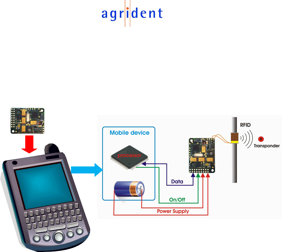
The Agrident ISO11784/11785 module is a low frequency OEM RFID reader module
working on 134.2 KHz. It has been designed for the integration into mobile devices
like PDAs. The ABR105 is not intended to be used as a stationary reader; stationary
means: power supply via an AC/DC converter connected to the mains and the
interface for communication connected to a desktop PC.
Agrident provides an Evaluation Board in order to make the development of an own
software interface easier for the customer. In case of using the ABR105 with the
Evaluation Kit, the reader board is powered by voltage regulators which are supplied
with 8 to 12V from a DC-source. The reader can be connected to a desktop PC using
either the RS232 or the USB connector on the Evaluation Board. However, this setup
is different from the use of the reader board in the final application and has the
purpose to evaluate the ABR105 only.
Power Supply options:
1) 2.5V – 4.2V DC (e.g. Lithium battery)
2) 5V from voltage regulator (linear, stabilized, low ripple voltage)
Interface options:
1) TTL interface (Rx, Tx, Gnd)
2) USB interface (for applications where the mobile device has an USB port)
2
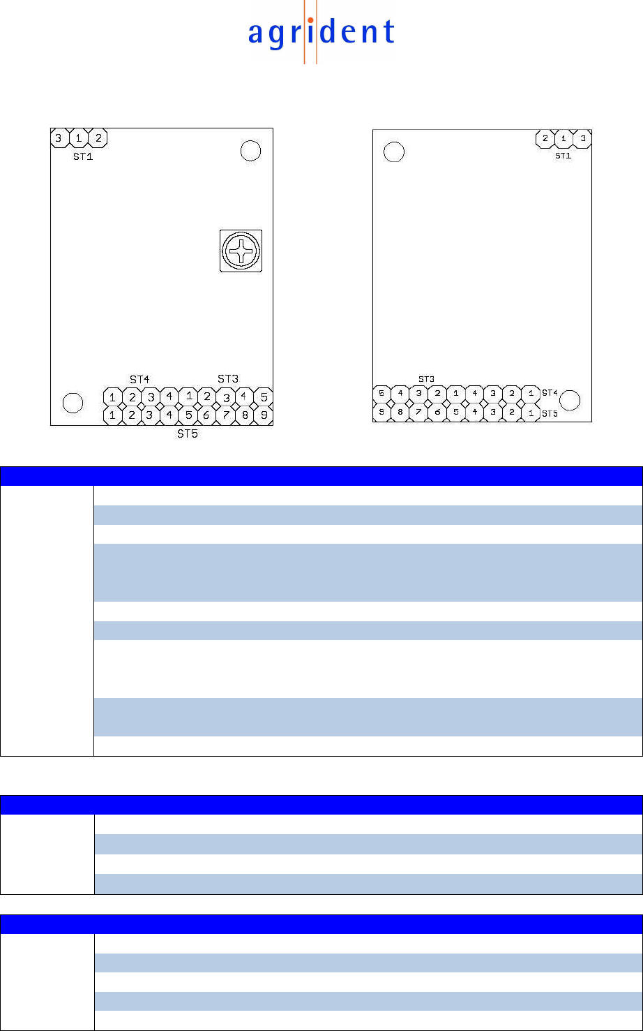
ISO-reader module, top-view ISO-reader module, bottom-view
Connector
Pin
Name
Type
Description
ST5
1 +U
Batt
IN Input voltage for 3.3V version (battery)
2 GND IN Common ground
3 +5V IN Input voltage for 5V version
4 +5V
out
+5VDC Switch-mode Power Supply
output, Has to be connected to ST5 Pin3
for 3.3V version
5 RxD-M IN Where the reader module receives data
6 TxD-M OUT Where the reader module transmits data
7 +5V
on
IN +5V in order to switch the module on
0V in order to switch the module off
(3.3V versions only!)
8 LED OUT Possibility to connect an external LED
(good read)
9 Int. use For internal use only
Connector
Pin
Name
Type
Description
ST4
1 +USB IN Supply voltage for the USB chip
2 USBDM I/O USB data minus
3 USBDP I/O USB data plus
4 GND USB IN USB ground
Connector
Pin
Name
Type
Description
ST3
1 TxD OUT USB transmit data
2 RxD OUT USB receive data
3 RTS OUT USB request to send
4 DTR OUT USB data terminal ready
5 TXDEN_S2
OUT Configurable CBUS Pin
3
Connector ST4 is a standard USB interface. ST3 provides the signals RxD and TxD
plus 3 additional control lines which can be used for controlling external electronics,
e.g. a barcode module. The status of these lines can be changed via commands on
the USB interface.
Connector
Pin
Description
ST1 1 Antenna 1
2 Antenna 2
3 Ground
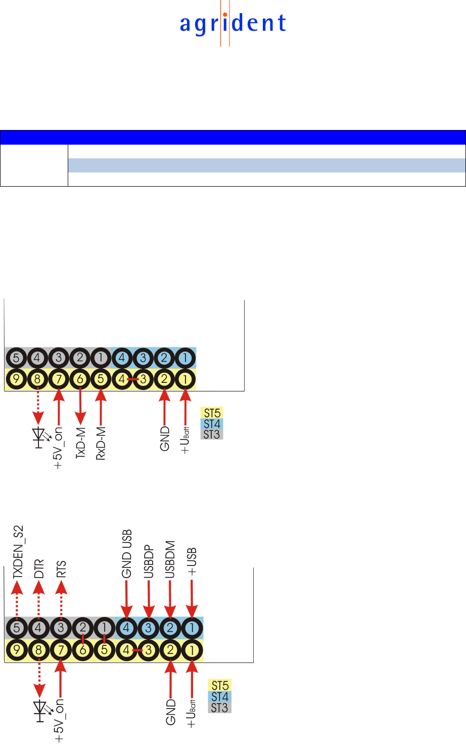
The following drawings show, how the reader module has to be connect and which
solder bridges have to be made for the corresponding modes:
3.3Volt TTL (Bottom view)
3.3V USB (Bottom view)
4
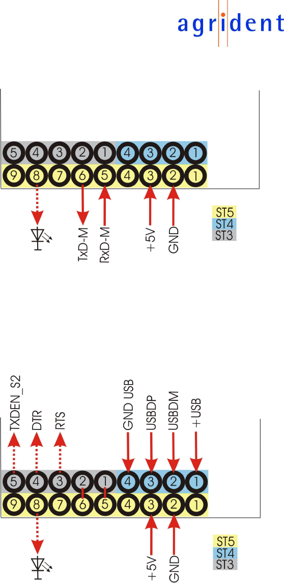
5V TTL (Bottom view)
5V USB (Bottom view)
5
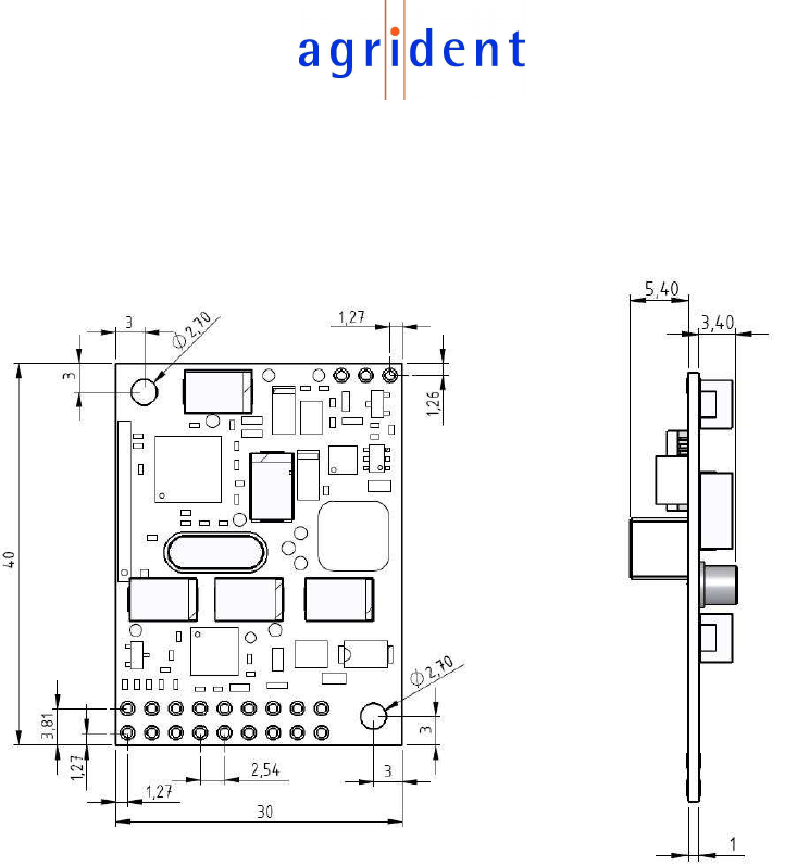
Mechanical Dimensions of the ABR105 Reader Module:
Bottom View
Side View
All dimensions in mm
Top Bottom
6
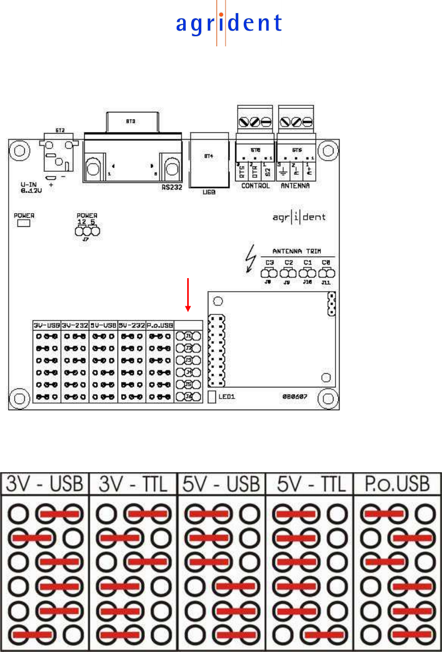
If the Evaluation Board is used, the different modes can be selected with jumpers:
The following combinations are possible:
ISO Reader
module

7
FCC and IC digital device limitations
The FCC approval is only valid with the tested antenna “ANT002”. If other antennas
should be used, the complete FCC Part 15 B test procedure has to be repeated!
Any additional antenna may be used with this device, provided that the new
antenna is from same type and has equal or lesser gain than the certified antenna(s).
The usage of any new antenna type or higher gain antenna require either a
Class II Permissive Change (add new antennas) by the Grantee (Agrident)
or a complete new authorization under a new FCC ID by the responsible party
for compliance.
Important Note:
This module is restricted to OEM integration due to the fact that this RF Module is not
equipped with an own shielding. The OEM integrator is still responsible for the
compliance to the FCC rules of the final end-product, which integrates this module.
Labeling of end product:
The final end-product must be labeled clearly visible with the following "Contains TX
FCC ID: QG2ABR105" and "Contains TX IC: 6252A-ABR105"
If the size of the end-product is larger than 8 x 10 cm, the following FCC Part 15.19
statement shall be also placed on the device:
This device complies with Part 15 of the FCC Rules.
Operation is subject to the following two conditions:
(1) this device may not cause interference, and
(2) this device must accept any interference, including interference that may cause
undesired operation of the device.
L'utilisation de ce dispositif est autorisée seulement aux deux conditions suivantes:
(1) il ne doit pas produire de brouillage, et
(2) l'utilisateur du dispositif doit être prêt à accepter tout brouillage radioélectrique
reçu, même si ce brouillage est susceptible de compromettre le fonctionnement du
dispositif.
If the size of the end product is too small (smaller than 8 x 10 cm) or it is not
practicable to place this statement on the end-product; this statement shall be placed
in a prominent location in the instruction manual or pamphlet supplied to the user or
alternatively shall be placed on the container in which the device is sold.

8
User Manual of the end-product:
The end user has to be informed that any changes or modifications not
expressly approved by the manufacturer could void the user’s authority to
operate this equipment.
FCC RF Radiation Exposure Statement
This equipment complies with FCC radiation exposure limits set forth for an
uncontrolled environment. End users must follow the specific operating instructions
for satisfying RF exposure compliance. This transmitter must not be co-located or
operating in conjunction with any other antenna or transmitter.
FCC §15.105 Information to the user
(a) For a Class A digital device or peripheral, the instructions furnished the user shall
include the following or similar statement, placed in a prominent location in the text of
the manual:
NOTE: This equipment has been tested and found to comply with the limits for a
Class A digital device, pursuant to part 15 of the FCC Rules. These limits are
designed to provide reasonable protection against harmful interference when the
equipment is operated in a commercial environment. This equipment generates,
uses, and can radiate radio frequency energy and, if not installed and used in
accordance with the instruction manual, may cause harmful interference to radio
communications. Operation of this equipment in a residential area is likely to cause
harmful interference in which case the user will be required to correct the interference
at his own expense.
Canadian Radio Emissions Requirement
This Class A digital apparatus complies with Canadian ICES-003. Cet appareil
numérique de la classe A est conforme à la norme NMB-003 du Canada.
9
CE MARKING
Hereby, Agrident BV declares that this equipment, if used according to the
instructions, is in compliance with the essential requirements and other relevant
provisions of the RTTE Directive 1999/5/EC. For use in all countries of the EU.
To obtain a copy, contact Agrident BV and request the “Declaration of Conformity”
document for Multi-technology readers.
Agrident BV
mail@agrident.com
In case of alteration of the product, not agreed to by us, this declaration will lose its
validity.
This symbol indicates proof of conformity to applicable European
Economic Community Council directives and harmonized
standards published in the official journal of the European
Communities.
Trouble shooting
For any problem please contact us:
Agrident GmbH
Steinklippenstr. 10
30890 Barsinghausen
Germany
Telephone +49 5105 582573-10
FAX +49 5105 582573-17
e-mail info@agrident.com