Agrident AIR200 Proximity Reader User Manual AIR man e
AGRIDENT GmbH Proximity Reader AIR man e
UserManual.wiki
>
Agrident
>
AIR200 User Manual
>
User Manual 1
Contents
1.
User Manual 1
2.
User Manual 2
User Manual 1
Navigation menu
Upload a User Manual
Namespaces
Wiki Guide
HTML
PDF
Info
Views
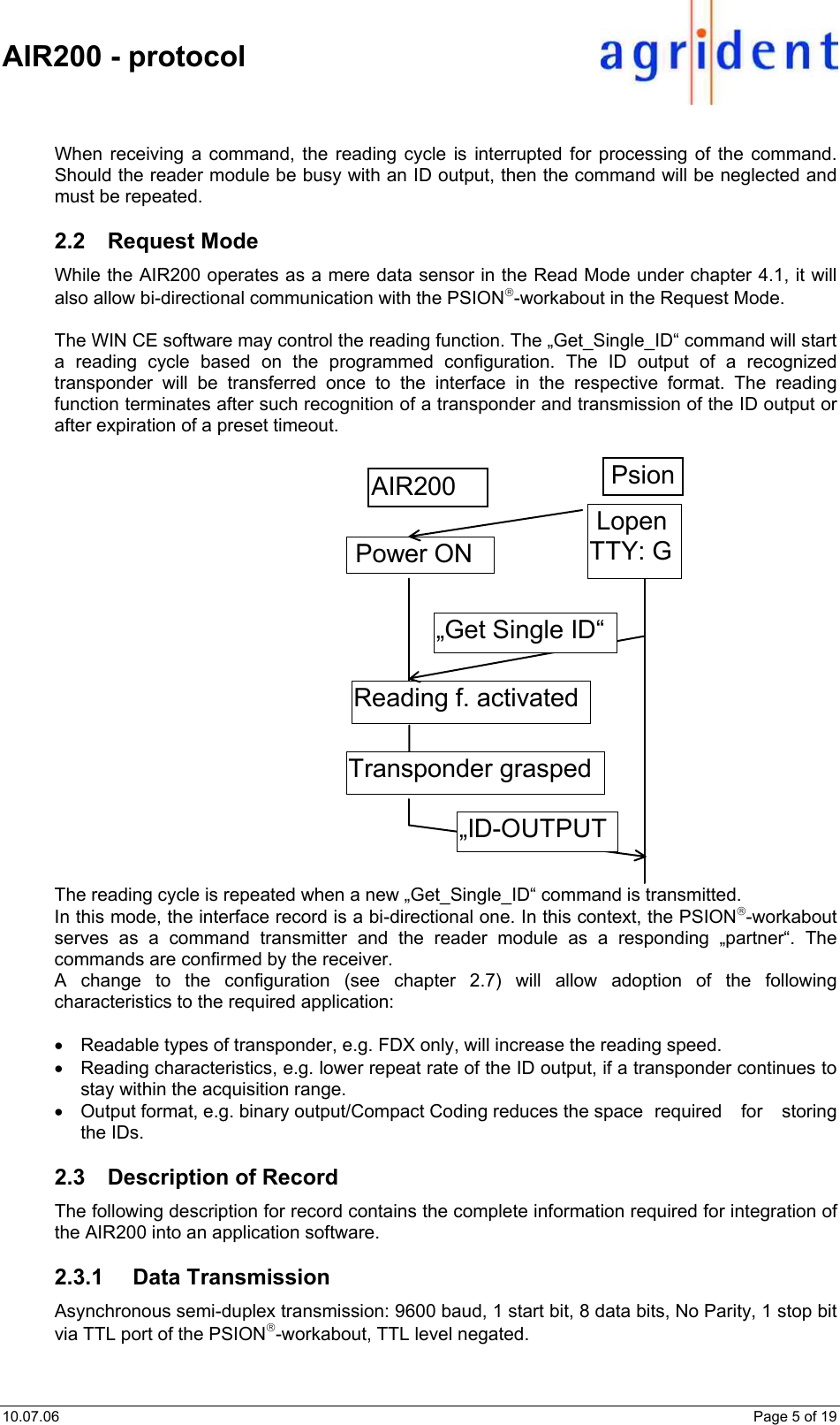
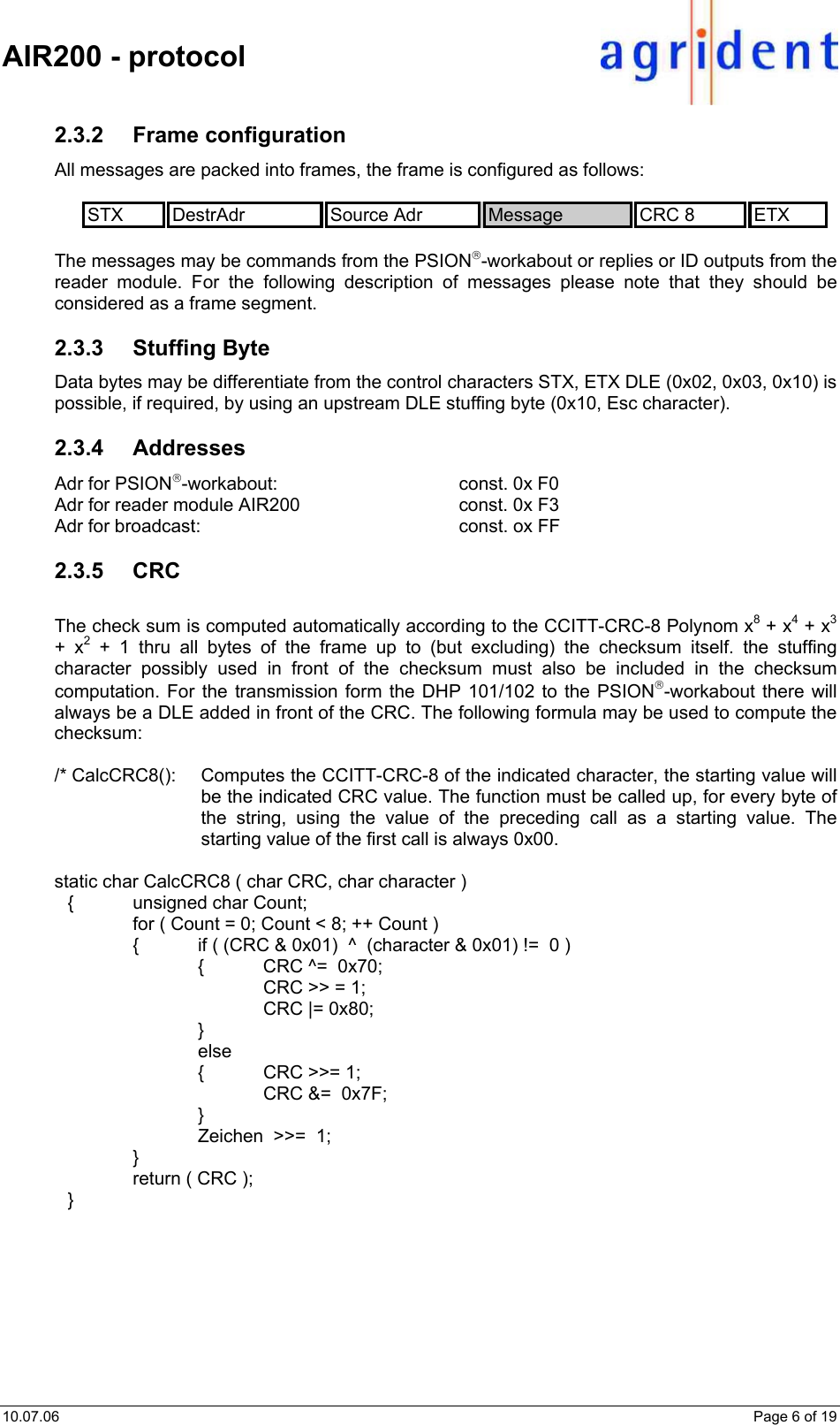
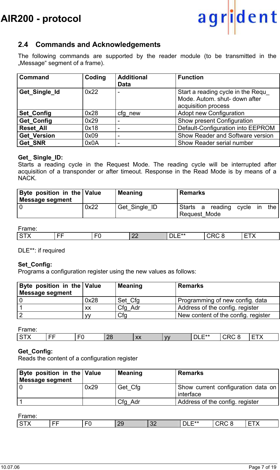
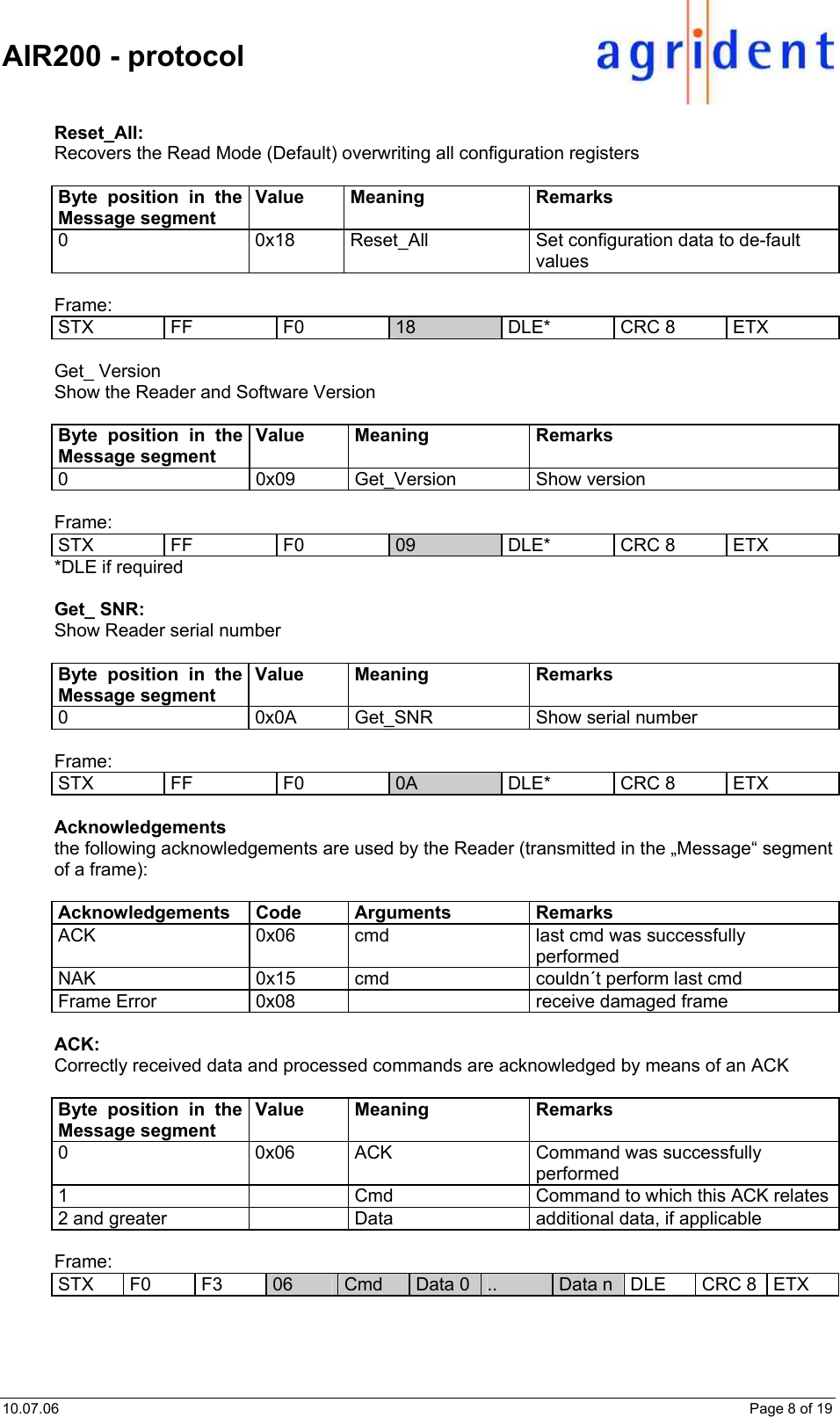
User Manual
Discussion / Help
Navigation