Agrident AIR200 Proximity Reader User Manual AIR man e
AGRIDENT GmbH Proximity Reader AIR man e
Agrident >
Contents
- 1. User Manual 1
- 2. User Manual 2
User Manual 1

Agrident GmbH, Steinklippenstr. 10, D-30890 Barsinghausen
Phone +49 5105 520614 - Fax +49 5105 520616
AIR200
Reader Operation
Manual
V10/07/06

AIR200 - manual
10.07.06 Page 2 of 19
© Copyright 2006 by Agrident GmbH
All rights reserved. No part of this publication may be reproduced, stored in a retrieval system,
or transmitted, in any form or by any means, electronic, mechanical, photocopying, recording or
otherwise, without prior written permission of Agrident GmbH.
Agrident reserves the right to make changes to any and all parts of this documentation without
obligation to notify any person or entity of such changes.
July 2006 HRU/BUS
Agrident GmbH
Steinklippenstr. 10
30890 Barsinghausen
Germany
Phone +49 51 05 520614
Fax +49 51 05 520616
E-Mail: mail@agrident.com
www.agrident.com

AIR200 - manual
10.07.06 Page 3 of 19
Contents
1. Introduction.......................................................................................................... 4
2. Operating Mode................................................................................................... 4
2.1 Read Mode / Default Setting ........................................................................ 4
2.2 Request Mode.............................................................................................. 5
2.3 Description of Record................................................................................... 5
2.3.1 Data Transmission ................................................................................ 5
2.3.2 Frame configuration .............................................................................. 6
2.3.3 Stuffing Byte.......................................................................................... 6
2.3.4 Addresses ............................................................................................. 6
2.3.5 CRC ...................................................................................................... 6
2.4 Commands and Acknowledgements............................................................ 7
2.5 ID Output...................................................................................................... 9
2.6 Output formats for the ID Field ................................................................... 10
2.6.1 ASCII Output (Default Setting) ............................................................ 10
2.6.2 Compact Coding Output...................................................................... 11
2.6.3 Transponder Byte Structure Output .................................................... 11
2.6.4 Raw Data Output................................................................................. 12
2.6.5 ID Type Field....................................................................................... 12
2.7 Optional Configurations.............................................................................. 13
2.7.1 Activation of the external antenna ....................................................... 14
2.8 Examples of ID -Messages ........................................................................ 15
2.8.1 ISO-FDX-B and HDX .......................................................................... 15
2.8.2 H 4002 and Compatibles..................................................................... 16
3. Trouble shooting................................................................................................ 17
AIR200 - protocol
10.07.06 Page 4 of 19
1. Introduction
The reader module AIR200 for the PSION TEKLOGIX is a high quality component from
AGRIDENT.
Together with the programmable PSION TEKLOGIX -workabout PRO handheld computer you
have a powerful mobile RF-ID-system which can easily adapt to your application.
Please read this manual carefully before using the system for the first time. The following
descriptions will help you using the full efficiency of the system. A description of the protocols
will give you some information for embedding the reader into your own application on the
PSION TEKLOGIX -workabout PRO to profit from all benefits and features the system offers to
you.
2. Operating Mode
The reader modules support two operating modes, selectable as per configuration.
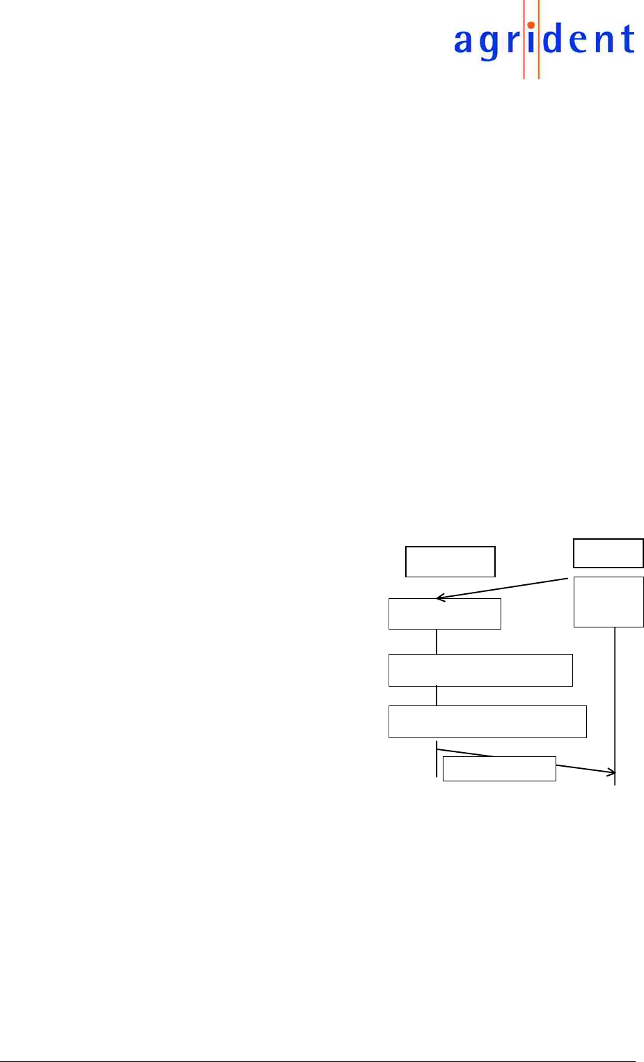
2.1 Read Mode / Default Setting
The AIR200 reader modules are set to the read mode (default mode) by the manufacturer of the
equipment. The reader module starts a reading cycle as soon as the supply voltage is applied
(controlled by the PSION´s application software; LOPEN TTY:G). When a transponder is
detected, the acquired and processed transponder data are ASCII coded as an „ID output“ and
transferred to the serial interface. The ID output is repeated for as long as the transponder is
located within the acquisition range.
The format of the ID output is described at
chapter 5.3. The communication is
unidirectional from the reader to the
PSION-workabout, with no response
required. It is not required that the entire
record of the reader module be implemented
into the application software, when limited to
the read mode. The ID output may be
received as a simple ASCII string and the
frame may be cut off.
Power ON
AIR200 Psion
Reading f. activated
ID-OUTPUT
Lopen
TTY: G
Transponder grasped
AIR200 - protocol
10.07.06 Page 5 of 19
When receiving a command, the reading cycle is interrupted for processing of the command.
Should the reader module be busy with an ID output, then the command will be neglected and
must be repeated.
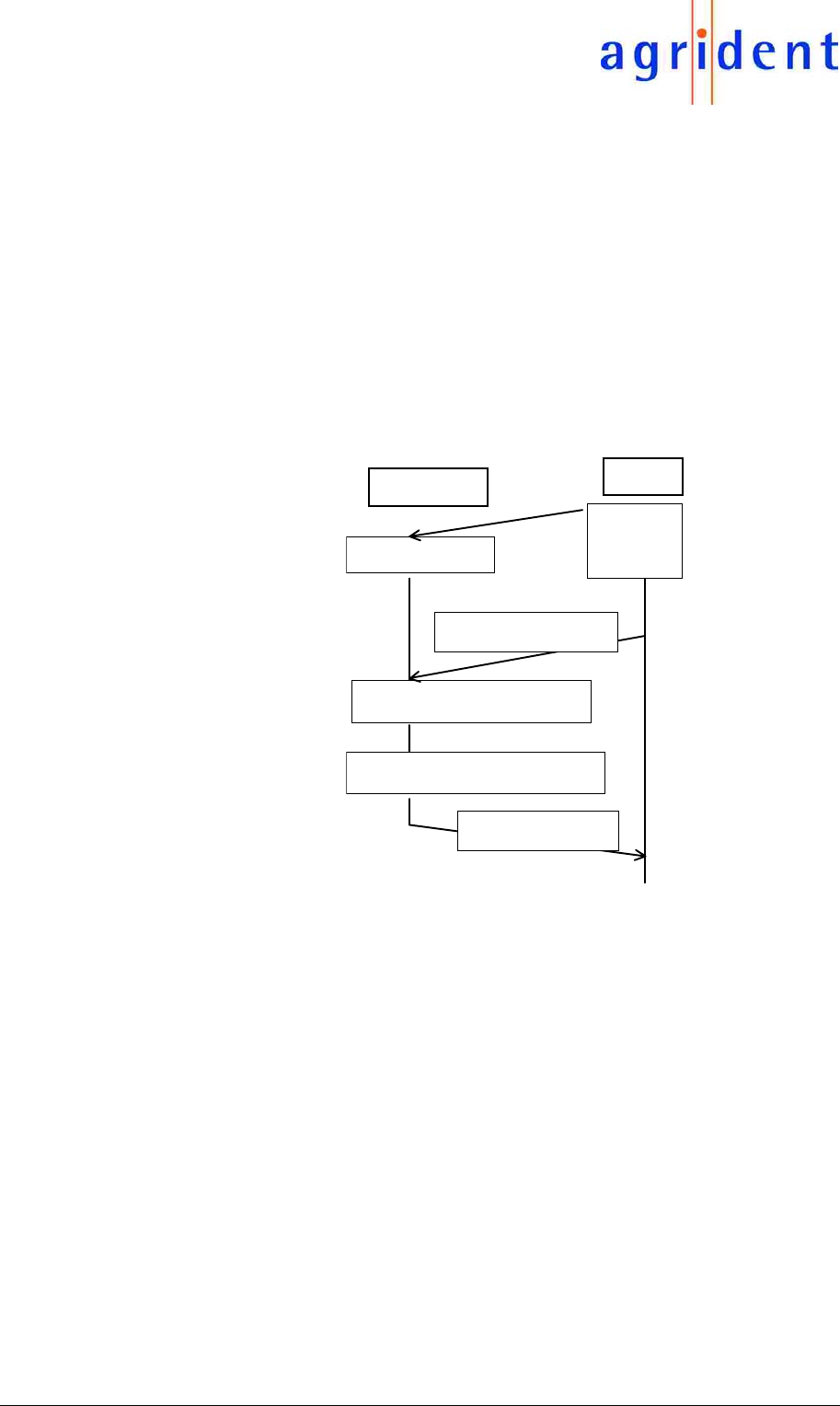
2.2 Request Mode
While the AIR200 operates as a mere data sensor in the Read Mode under chapter 4.1, it will
also allow bi-directional communication with the PSION-workabout in the Request Mode.
The WIN CE software may control the reading function. The „Get_Single_ID“ command will start
a reading cycle based on the programmed configuration. The ID output of a recognized
transponder will be transferred once to the interface in the respective format. The reading
function terminates after such recognition of a transponder and transmission of the ID output or
after expiration of a preset timeout.
Power ON
AIR200 Psion
Reading f. activated
„ID-OUTPUT
Lopen
TTY: G
„Get Single ID“
Transponder grasped
The reading cycle is repeated when a new „Get_Single_ID“ command is transmitted.
In this mode, the interface record is a bi-directional one. In this context, the PSION-workabout
serves as a command transmitter and the reader module as a responding „partner“. The
commands are confirmed by the receiver.
A change to the configuration (see chapter 2.7) will allow adoption of the following
characteristics to the required application:
• Readable types of transponder, e.g. FDX only, will increase the reading speed.
• Reading characteristics, e.g. lower repeat rate of the ID output, if a transponder continues to
stay within the acquisition range.
• Output format, e.g. binary output/Compact Coding reduces the space required for storing
the IDs.
2.3 Description of Record
The following description for record contains the complete information required for integration of
the AIR200 into an application software.
2.3.1 Data Transmission
Asynchronous semi-duplex transmission: 9600 baud, 1 start bit, 8 data bits, No Parity, 1 stop bit
via TTL port of the PSION-workabout, TTL level negated.

AIR200 - protocol
10.07.06 Page 6 of 19
2.3.2 Frame configuration
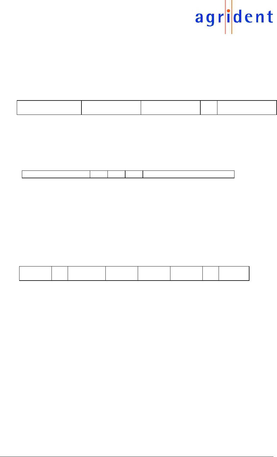
All messages are packed into frames, the frame is configured as follows:
STX DestrAdr Source Adr Message CRC 8 ETX
The messages may be commands from the PSION-workabout or replies or ID outputs from the
reader module. For the following description of messages please note that they should be
considered as a frame segment.
2.3.3 Stuffing Byte
Data bytes may be differentiate from the control characters STX, ETX DLE (0x02, 0x03, 0x10) is
possible, if required, by using an upstream DLE stuffing byte (0x10, Esc character).
2.3.4 Addresses
Adr for PSION-workabout: const. 0x F0
Adr for reader module AIR200 const. 0x F3
Adr for broadcast: const. ox FF
2.3.5 CRC
The check sum is computed automatically according to the CCITT-CRC-8 Polynom x8 + x4 + x3
+ x2 + 1 thru all bytes of the frame up to (but excluding) the checksum itself. the stuffing
character possibly used in front of the checksum must also be included in the checksum
computation. For the transmission form the DHP 101/102 to the PSION-workabout there will
always be a DLE added in front of the CRC. The following formula may be used to compute the
checksum:
/* CalcCRC8(): Computes the CCITT-CRC-8 of the indicated character, the starting value will
be the indicated CRC value. The function must be called up, for every byte of
the string, using the value of the preceding call as a starting value. The
starting value of the first call is always 0x00.
static char CalcCRC8 ( char CRC, char character )
{ unsigned char Count;
for ( Count = 0; Count < 8; ++ Count )
{ if ( (CRC & 0x01) ^ (character & 0x01) != 0 )
{ CRC ^= 0x70;
CRC >> = 1;
CRC |= 0x80;
}
else
{ CRC >>= 1;
CRC &= 0x7F;
}
Zeichen >>= 1;
}
return ( CRC );
}
AIR200 - protocol
10.07.06 Page 7 of 19
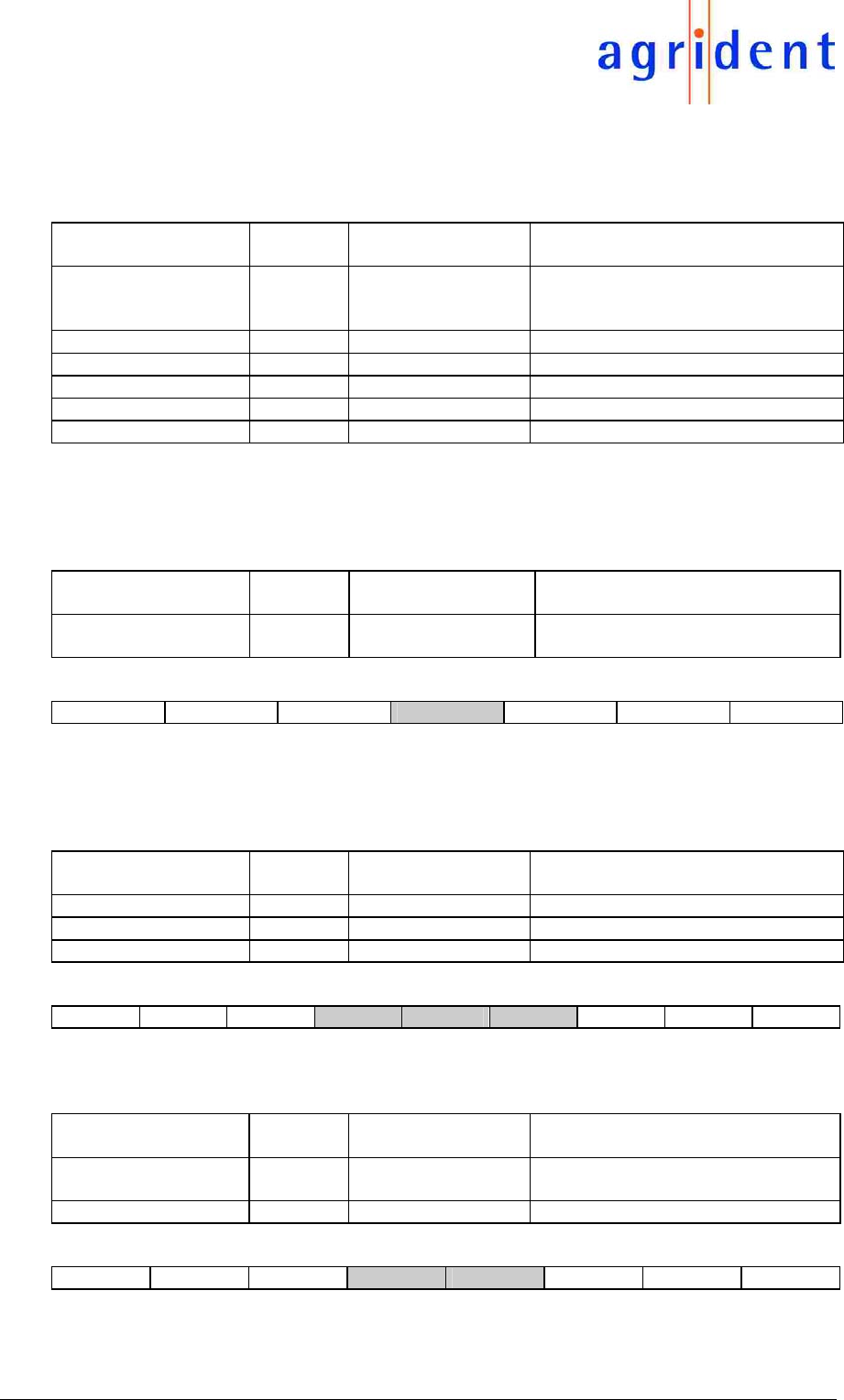
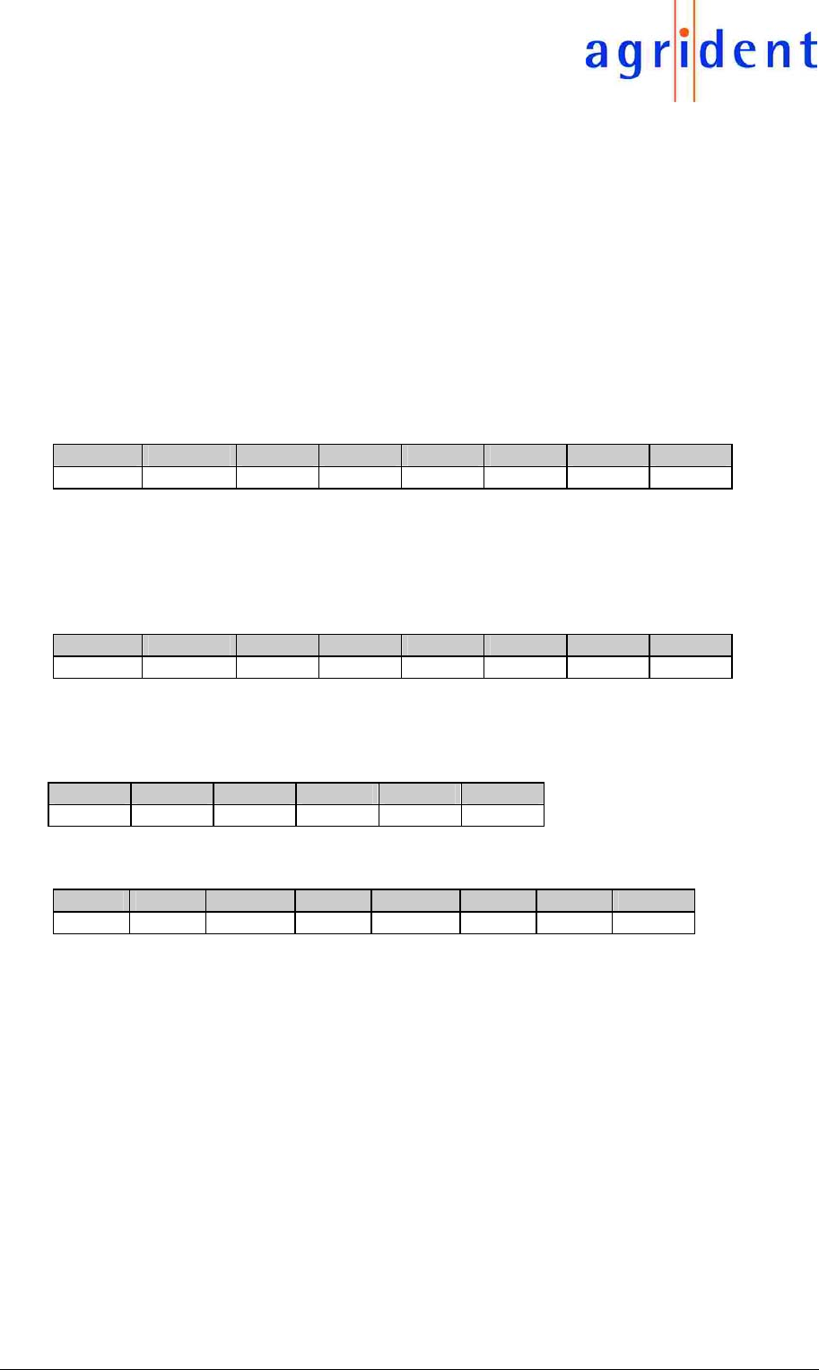
2.4 Commands and Acknowledgements
The following commands are supported by the reader module (to be transmitted in the
„Message“ segment of a frame).
Command Coding Additional
Data
Function
Get_Single_Id 0x22 - Start a reading cycle in the Requ_
Mode. Autom. shut- down after
acquisition process
Set_Config 0x28 cfg_new Adopt new Configuration
Get_Config 0x29 - Show present Configuration
Reset_All 0x18 - Default-Configuration into EEPROM
Get_Version 0x09 - Show Reader and Software version
Get_SNR 0x0A - Show Reader serial number
Get_ Single_ID:
Starts a reading cycle in the Request Mode. The reading cycle will be interrupted after
acquisition of a transponder or after timeout. Response in the Read Mode is by means of a
NACK.
Byte position in the
Message segment
Value Meaning Remarks
0 0x22 Get_Single_ID Starts a reading cycle in the
Request_Mode
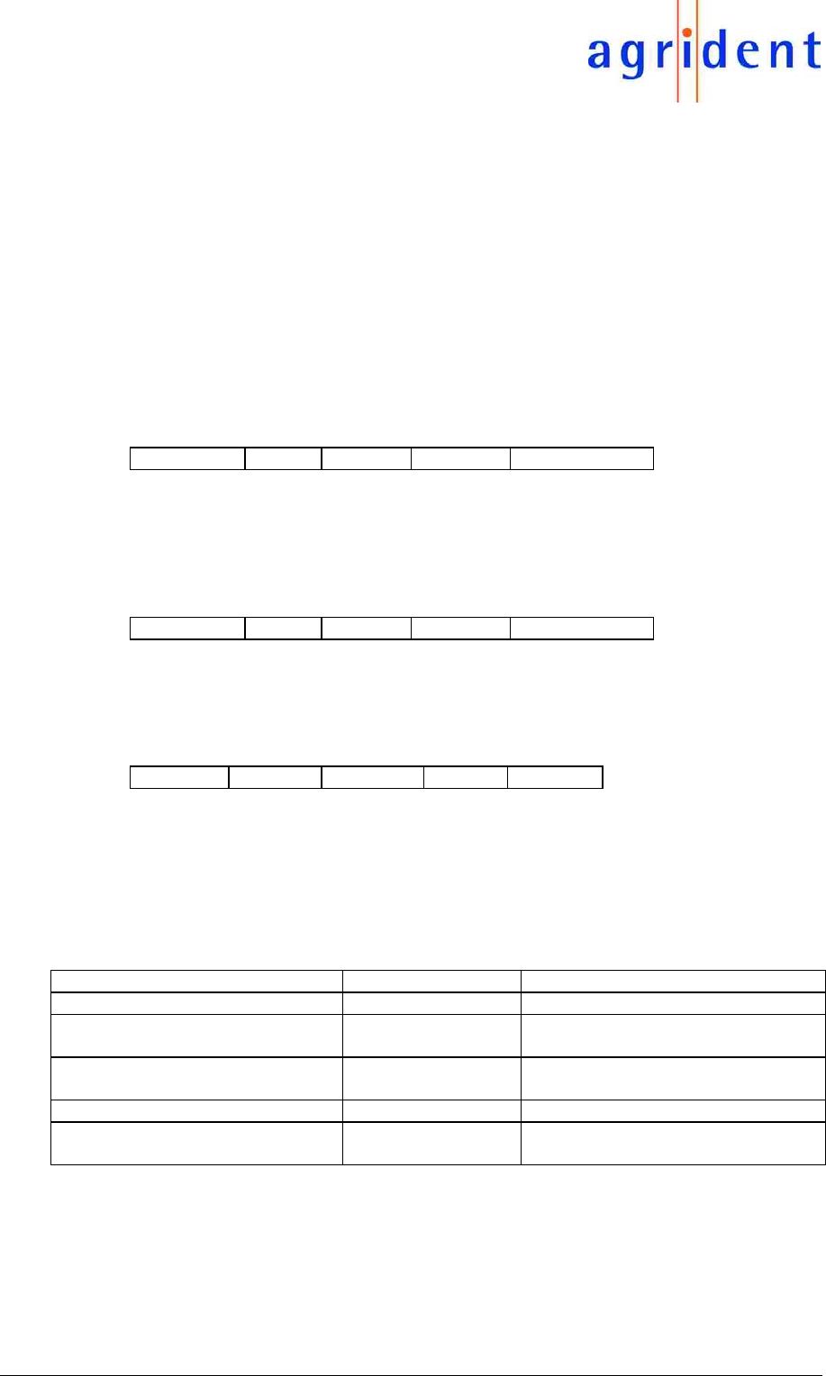
Frame:
STX FF F0 22 DLE** CRC 8 ETX
DLE**: if required
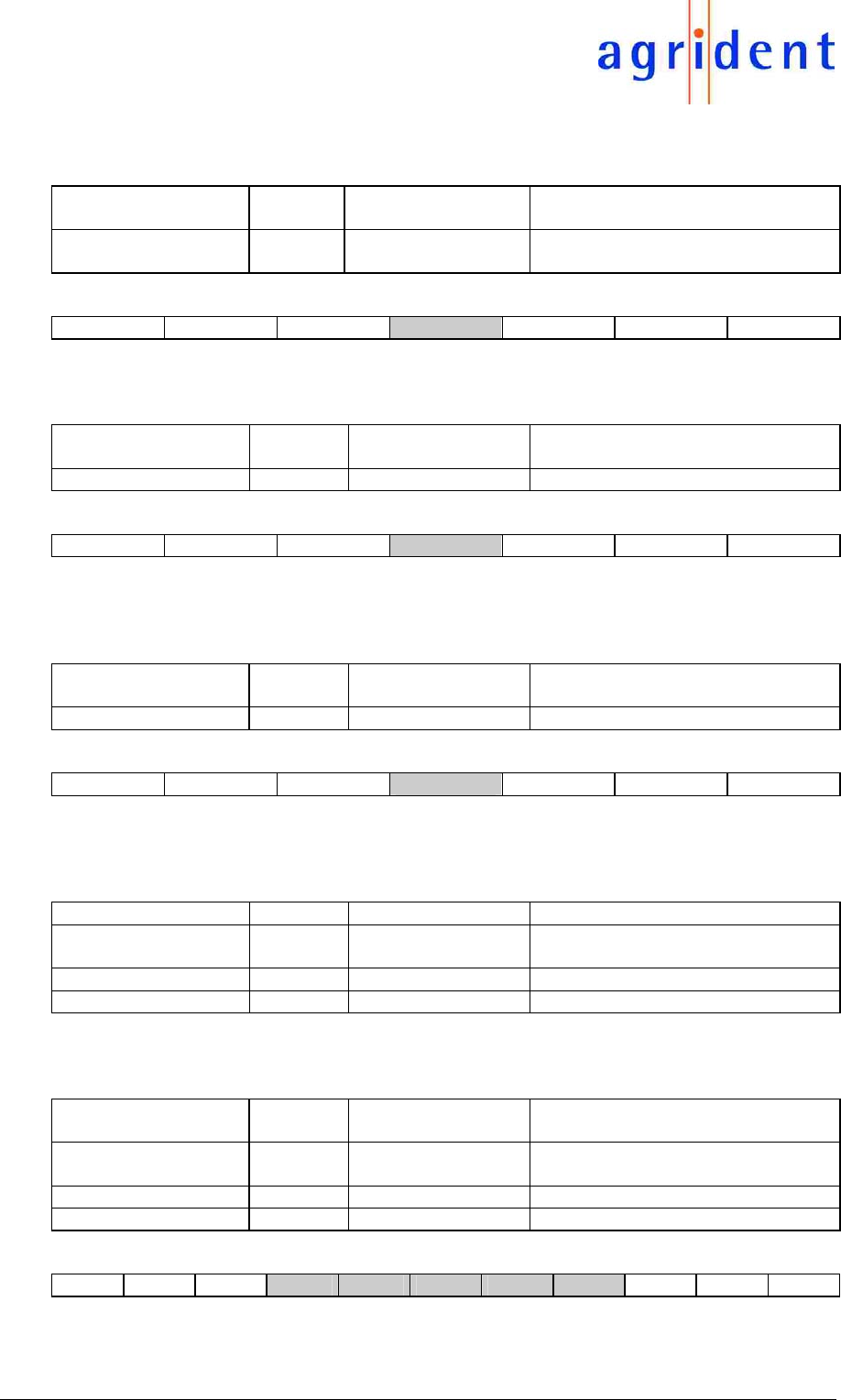
Set_Config:
Programs a configuration register using the new values as follows:
Byte position in the
Message segment
Value Meaning Remarks
0 0x28 Set_Cfg Programming of new config. data
1 xx Cfg_Adr Address of the config. register
2 yy Cfg New content of the config. register
Frame:
STX FF F0 28 xx yy DLE** CRC 8 ETX
Get_Config:
Reads the content of a configuration register
Byte position in the
Message segment
Value Meaning Remarks
0 0x29 Get_Cfg Show current configuration data on
interface
1 Cfg_Adr Address of the config. register
Frame:
STX FF F0 29 32 DLE** CRC 8 ETX
AIR200 - protocol
10.07.06 Page 8 of 19
Reset_All:
Recovers the Read Mode (Default) overwriting all configuration registers
Byte position in the
Message segment
Value Meaning Remarks
0 0x18 Reset_All Set configuration data to de-fault
values
Frame:
STX FF F0 18 DLE* CRC 8 ETX
Get_ Version
Show the Reader and Software Version
Byte position in the
Message segment
Value Meaning Remarks
0 0x09 Get_Version Show version
Frame:
STX FF F0 09 DLE* CRC 8 ETX
*DLE if required
Get_ SNR:
Show Reader serial number
Frame:
STX FF F0 0A DLE* CRC 8 ETX
Acknowledgements
the following acknowledgements are used by the Reader (transmitted in the „Message“ segment
of a frame):
Acknowledgements Code Arguments Remarks
ACK 0x06 cmd last cmd was successfully
performed
NAK 0x15 cmd couldn´t perform last cmd
Frame Error 0x08 receive damaged frame
ACK:
Correctly received data and processed commands are acknowledged by means of an ACK
Byte position in the
Message segment
Value Meaning Remarks
0 0x06 ACK Command was successfully
performed
1 Cmd Command to which this ACK relates
2 and greater Data additional data, if applicable
Frame:
STX F0 F3 06 Cmd Data 0 .. Data n DLE CRC 8 ETX
Byte position in the
Message segment
Value Meaning Remarks
0 0x0A Get_SNR Show serial number

AIR200 - protocol
10.07.06 Page 9 of 19
Example:
Content of the Data field:
after the Get_Version command: DHP101V1.05“ (ASCII)
after the Get_SNR command: 000023 (ASCII)
NACK:
No correct data received, unknown commands or „not able to process commands“ results in a
NACK
Byte position in the
Message segment
Value Meaning Remarks
0 0x15 NACK Unable to process command
1 Command Command to which this NACK
relates
2 Error Error Code, e.g. 01=unknown
command
Frame:
STX F0 F3 15 Cmd 01 DLE CRC 8 ETX
2.5 ID Output
After recognition of a transponder, the related ID is transmitted according to the pre-set format
as an Output ID.
Message Code Arguments Remarks
ID_Output 0x23 ID ID received follows in the frame
Frame:
STX F0 F3 23 ID 0 ..... ID n DLE CRC 8 ETX
Due to the different lengths (depending on type of transponder and on output format) an
interlaced string is used as an ID output structure. This list contains the ID field with the
transponder identification and the „type“ field with the transponder type.
Construction of the ID output:
Byte position in the
Message segment
Value Meaning Remarks
0 0x23 ID Output Identification: This is an ID Output
1 Ptr1 Length of the ID field incl. Ptr 1
2 ID Field ID Field Data of length „n Bytes“
2+n Ptr2 Length of the Type Field incl. Ptr2
3+n Type Field Type Field Data of length „m Bytes“
3+n+m 0x00 0-Ptr as a termination mark
Message (ID):
23 Ptr1 ID field 0 . ID Field n Ptr2 Type Field 0 .. Type Field M 00

AIR200 - protocol
10.07.06 Page 10 of 19
2.6 Output formats for the ID Field
The output format is defined by the configuration of the Cfg_Format“ Register by means of a
„Set_Config“ command. The following formats are supported:
Output
Format
Value of
Cfg Format
Fmt_
Deziso
Fmt_
Bin
Fmt_
Raw
Data
Remarks Bytes
for
ISO
Bytes
for
4002
ASCII
(default)
0x01 1 0 0 ID field is ASCII coded
for FDX-B and HDX
ID and Country Code
I.A.W. ISO 11784 for
H 4002 data
16 10
Com-pact
Coding
(binary)
0x03 1 1 0 ID field is binary coded
for FDX-B and DDX: ID
and Country Code
I.A.W. ISO 11784 for H
4002 data
8 5
Trans.
Byte
Struct.
0x02 0 1 0 Data I.A.W. ISO are
binary coded for FDX
and HDX: Data (ID,
Country Code, reserv.
data field, Animalflag) +
CRC + Trailer for H
4002 correspond to
„Compact Coding“
13 5
Transp.
„Raw
Data“
0x06
or
0x07
don´t
care
1 1 Raw Data: binary coded
for FDX-B: 128 bit raw
data
for HDX: 104 bit raw
data (w/o header,
prebits) for
H 4002 64 bit raw data
16
HDX:
13
8
2.6.1 ASCII Output (Default Setting)
The ID output comprised of ID and Country Code as per ISO is transferred in the ASCII format.
Transponders with invalid CRC or parity bits are rejected. The reserved data field, CRC and
Trailer are not transferred under this format.
• FDX-B and HDX Transponders:
16 ASCII coded characters (16 Bytes), MSDigit first.
Cty_ ASCII_Char_3 ... Cty_ ASCII_Char_0 ID_ ASCII_Char_12 ... ID_ ASCII_Char_0
Cty_ASCII_Char_n: The number „n“ byte of the Country Code according to ISO ( consists
of 4 digits 0-9) coded in ASCII.
ID_ASCII_Char_n: Number „n“ byte of the ID code (consists of 12 digits 0-9) coded in
ASCII.
• H 4002 transponders and compatibles:
10 ASCII coded characters (10 Bytes) MSDigit first.
ASCII_Char_9 ... ... ... ASCII_Char_0
ASCII_Char_n: Number „n“ byte of the ID code (consists of 10 digits 0-9) coded in
ASCII.
AIR200 - protocol
10.07.06 Page 11 of 19
2.6.2 Compact Coding Output
The ID Output comprised of the ID and the Country Code is tranferred in the binary format. ID
outputs with an invalid CRC or parity bit will be rejected. The reserved data field, CRC and
Trailer are not transferred under this format.
• FDX-B and HDX transponders:
16 BCD coded numbers (8 Bytes), MSDigit first
Cty_BCD_3 :
Cty_BCD_2
Cty_BCD_1 :
Cty_BCD_0
ID_BCD_11 :
ID_BCD_10
... ID_BCD_1 :
ID_BCD_0
Cty_BCD_n: The number „n“ half-byte of the Country Code according to ISO (consists of 4
digits 0-9) coded in BCD.
ID_BCD_n: Number „n“ half-byte of the ID code (consists of 12 digits 0-9) coded in BCD.
• H 4002 transponders and compatibles:
10 hex-coded numbers (5 Bytes), MSDigit first
Hex_9 : Hex_8 ... ... ... Hex_1 : Hex_0
Hex_n: The number „n“ half-byte of the ID Code (consists of 10 hexa-digits 0-9) coded in
BCD.
2.6.3 Transponder Byte Structure Output
The useful data from ISO - FDX-B/HDX transponders (ID, Country Code, reserved data field,
Animal Flag) are outputted in a bibary format according to the sequence of receipt, including the
CRC and trailer.The LSBit of an output Byte is the Bit first received by the transponder.
ID outputs with an invalid CRC according to ISO will be rejected.
• FDX-B and HDX transponders:
13 Bytes
ID_
Byte_0
.. ID_
Byte_7
CRC_
Byte_0
CRC_
Byte_1
Trail_
Byte_0
.. Trail_
Byte_2
ID_Byte_n: Number „n“ Byte of the Bit structure according to ISO (consists of 64 bit),
binary coded with reserved data field.
CRC_Byte_n: Number „n“ Byte of the CRC according to ISO (consists of two Byte),
binary coded,
Trail_Byte_n: Number „n“ Byte of the Trailer according to ISO (consists of 3 Byte),
binary coded.
• H 4002 transponder and compatibles:
in conformance with the „Compact Coding“ format.
AIR200 - protocol
10.07.06 Page 12 of 19
2.6.4 Raw Data Output
The complete set of raw data from a transponder are outputted in a binary format, in the
sequence of receipt. The LSBit of an outputted Byte is the first bit received from the
transponder.
For ISO transponders, the useful data (ID, Countra Code, reserve data field, Animal Flag) CRC
and Trailer are included. For FDX-B transponders, the header and control bits are included.
ID Outputs with an invalid CRC according to ISO (or an incorrect parity bit for H 4002) are not
rejected, which allows reading of transponders with a different structure. (for HDX only in case
the header is identical). the absence of error check will also lead to an output of data received
with bit errors.
• FDX-B transponders, 16 Bytes:
Useful data (starting with Byte 0), CRC and Trailer (with control bits each), Header,
Byte_0 ... ... ... Byte_15
Byte_n: Number „n“ Byte of the ID Code
• HDX- transponders, 13 Bytes:
Useful data CRC and Trailer without Header (01111110)
Byte_0 ... ... ... Byte_13
Byte_n_ Number „n“ Byte of the ID Code
• H 4002 transponders and compatibles:
8 Bytes: with Header and Parity Bits
Byte_0 ... ... ... Byte_7
Byte_n: Number „n“ Byte of the ID Code (Byte 0= Header)
2.6.5 ID Type Field
The “type field“ designates the type of transponder. The „ID type“ field output takes place in the
ASCII Mode with 2 ASCII characters, or else with a Byte (binary).
Transponder Type Value Remarks
HDX 01 HDX transponder according to ISO
H 4002 02 applies also to compatibles (H
4001/3/4...no electrical difference)
FDX-B 05 FDX-B transponders according to
ISO
unknown 7F non-decodable data
no transponder FF no transponder within the active
field
If a „Get single ID“ is interrupted in the Request Mode due to timeout, then an empty „ID Output“
without ID Field is outputted, with ID Field Type „FF“.

AIR200 - protocol
10.07.06 Page 13 of 19
2.7 Optional Configurations
This chapter describes the use of the configuration register. The configuration commands
enable the purposeful configuring of the DHP 101/102 Reader Module according to the desired
application.
Register Cfg_Adr Bit No. (0...7) of
Register: Name
Meaning of the Bit when set to „1“ Def.-
Value
Cfg_
mode
0x31 Operating Mode 0x00
1: Mode-Requ Request Mode: After switch-on wait for
command (otherwise „Read Mode“)
Cfg_
Format
0x32 Format of the ID Output 0x01
0: Fmt_Deziso Decoding of the trans-ponder data for
FDX-B I.A.W. ISO 11784 (otherwise:
output Trans-ponder Byte Structure)
1
1: Fmt_Bin Output is binary (otherwise ASCII) 0
2: Fmt_Raw_Data Output Raw Data w/o CRC or Parity
Check (otherwise done only if check is
OK)
0
Cfg_Rf 0x33 Configuration of the RF Interface 0x0E
1: Rf_FDXB_on FDXB Reception activated (otherwise
(FDXB and H4002 Reception off-line)
1
2: Rf_HDX_on HDX Reception activated (otherwise
HDX Reception off-line)
1
3: Rf_H4002_on H4002 Reception activated (only if FDX-
B is active, otherwise offline
1
Cfg_
Timeout
0x34 Read function switch-off time for a
„Get_Single_ID in the Request Mode if
no ID was received until then:
Time=Register Value x appr. 50 ms
(Register Value 0x00also yields appr.
50 ms)
0x00
Cfg_
Delay
time
0x35 Waiting Time for Repeat of ID Output
already transmitted in the Read Mode:
Time=
Register Value x appr. 50 ms
(Register Value 0x00 means no repeat
of same ID)
0x01
Cfg_IO
Function
0x37 External Antenna 0x00
0: external
antenna on
External Antenna activated (otherwise
external antenna deactivated)
0
The Configuration Register Cfg_Mode defines the Read- or Request Mode.
The Cfg_Format Configuration Register is used for setting the output format of the transponder
ID.
The Cfg_RF determines the type of transponder to be read.
The Configuration Register Cfg_Timeout defines the switch-off time for a reading cycle in the
Request Mode.
By means of the Configuration Register Cfg_Delaytime, you may determine the repeat rate for
the same ID Output.
AIR200 - protocol
10.07.06 Page 14 of 19
The Cfg_IOFunction determines whether the external antenna is activated or not.
The configuration data are stored in an EEPROM and are preserved also after power shut
down.
If a „Set_Conf“ command is applied to a non-defined register, the system will respond with a
NACK message. Non-defined bits within a configuration register will be suppressed.
2.7.1 Activation of the external antenna
In order to activate the external antenna, the 'Set_Config' request has to be used.
The following command sequence has to be send to the AIR200:
Request:
STX DST SRC CMD ADR CFG CRC 8 ETX
0x02 0xFF 0xF0 0x28 0x37 0x01 0x73 0x03
ADR: Address of the configuration register (in this example 0x37 => IOFunction)
CFG: Configuration data to program into selected configuration register (in this example
0x01 => external antenna activated)
Answer:
STX DST SRC ACK CMD DLE CRC 8 ETX
0x02 0xF0 0x01 0x06 0x28 0x10 0x1C 0x03
Save the current configuration by sending 'Save_Config' request:
Request:
STX DST SRC CMD CRC 8 ETX
0x02 0xFF 0xF0 0x2A 0xC9 0x03
Answer:
STX DST SRC ACK CMD DLE CRC 8 ETX
0x02 0xF0 0x01 0x06 0x2A 0x10 0x4B 0x03
AIR200 - protocol
10.07.06 Page 15 of 19
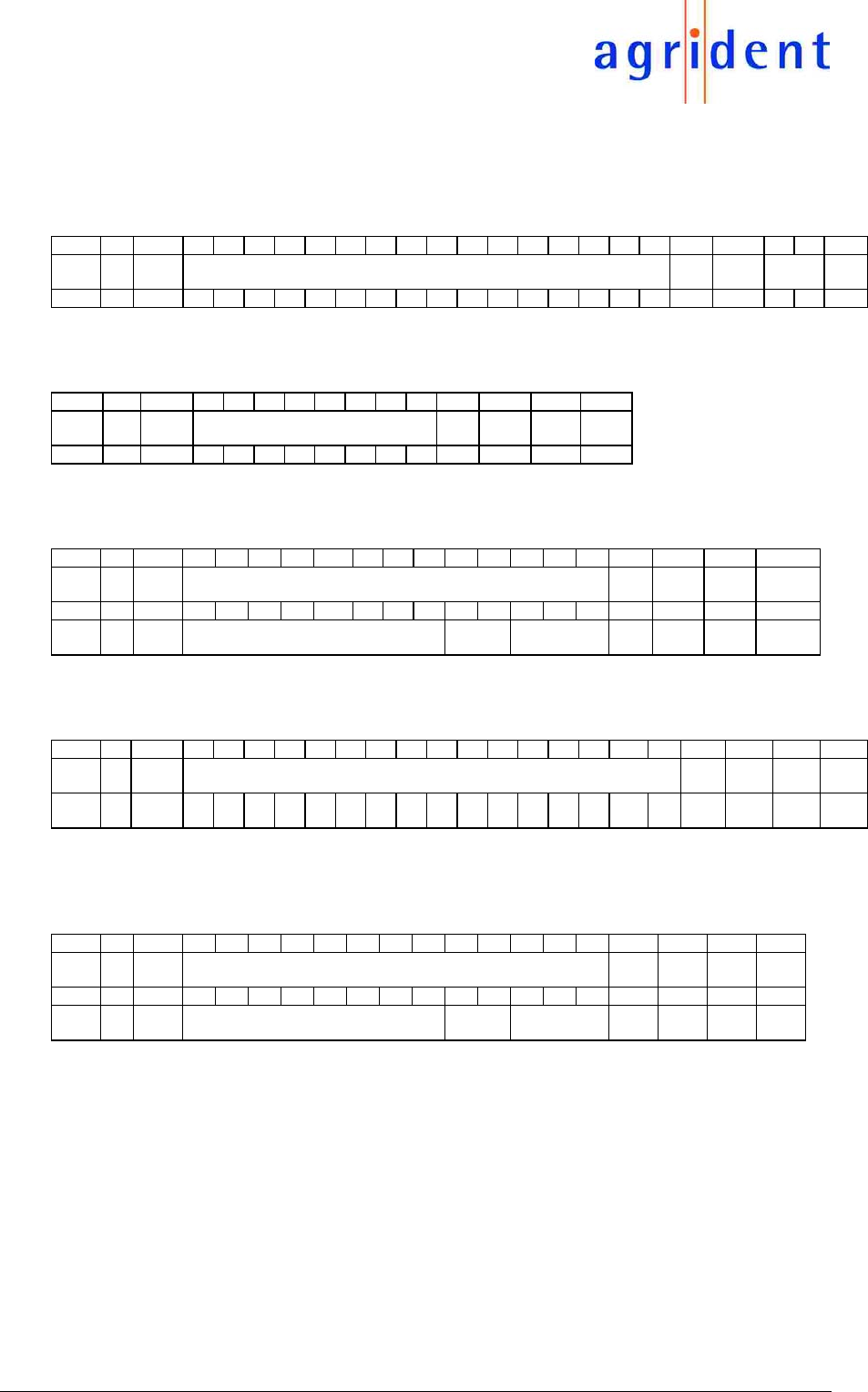
2.8 Examples of ID -Messages
2.8.1 ISO-FDX-B and HDX
a) ASCII Output
Pos 0 1 2 3 4 5 6 7 8 9 10 11 12 13 14 15 16 17 18 19 20 21 22
Re-
mark
ID Len1 ID 16 Byte DLE Len2 Type NUL
Ascii ‘#’ 11 ‘0’ ‘9’ ‘8’ ‘0’ ‘0’ ‘0’ ‘0’ ‘0’ ‘0’ ‘0’ ‘0’ ‘9’ ‘9’ ‘7’ ‘0’ ‘8’ 10 03 ‘0’ ‘5’ 00
b) Compact Coding Output
Pos 0 1 2 3 4 5 6 7 8 9 10 11 12 13
Re-
mark
ID Len1 ID 8 Byte DLE Len2 Type NUL
Bin 23 09 09 80 00 00 00 09 97 08 10 02 05 00
c) Transponder Byte Structure Output
Pos 0 1 2 3 4 5 6 7 8 9 10 11 12 13 14 15 16 17 18
Re-
mark
ID Len1 13 Byte DLE Len2 Type NUL
Bin 23 0E 7C 85 01 00 00 F5 00 80 0F F0 81 C4 A2 10 02 05 00
8 Databytes + ID, Country,
reserv. Data Animal flag
CRC Trailer
d) Transponder Raw Data Output for FDX-B Transponder
Pos 0 1 2 3 4 5 6 7 8 9 10 11 12 13 14 15 16 17 18 19 20 21
Re-
mark
ID Len1 Raw Data incl. Header, Yield Data ,CRC, Trailer (+Controllbits) = 128 Bits DLE Len2 Type NUL
Bin 23 11 7
C
0
B
07 04 08 B
0
3
E
40 C
0
0F E
1
07 26 2
E
1A 80 10 02 05 00
e) Transponder Raw Data Output for HDX Transponder corresponds to (c) for this type of
Transponder)
Pos 0 1 2 3 4 5 6 7 8 9 10 11 12 13 14 15 16 17 18
Re-
mark
ID Len1 Raw Data incl. Header, Yield Data ,CRC, Trailer = 104 Bits DLE Len2 Type NUL
Bin 23 0E 2F A7 0F 00 80 F5 00 80 A2 04 7E 00 01 10 02 01 00
8 Data Bytes + ID, Country,
reserv. Data, Animal flag
CRC Trailer or
Stopbyte
AIR200 - protocol
10.07.06 Page 16 of 19
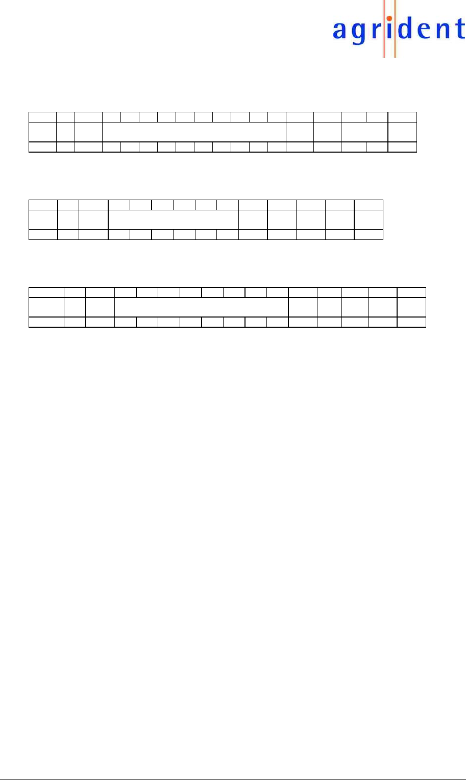
2.8.2 H 4002 and Compatibles
a) ASCII Output
Pos 0 1 2 3 4 5 6 7 8 9 10 11 12 13 14 15 16
Re-
mark
ID Len1 ID 10 Byte DLE Len2 Type NUL
Ascii ‘#’ 0B ‘0’ ‘4’ ‘6’ ‘0’ ‘2’ ‘0’ ‘9’ ‘B’ ‘2’ ‘E’ 10 03 ‘0’ ‘2’ 00
b) Compact Coding Output
Pos 0 1 2 3 4 5 6 7 8 9 10 11 12
Re-
mark
ID Len1 ID 5 Byte DLE Len2 DLE Type NUL
Hex 23 06 04 60 09 A8 F1 39 10 02 10 02 00
c) Transponder Raw Data Output
Pos 0 1 2 3 4 5 6 7 8 9 10 11 12 13 14
Re-
mark
ID Len1 Raw-ID incl. Header, Data, Trailer = 64 Bits DLE Len
2
DLE Type NUL
Bin 23 09 FF 81 34 80 82 D4 E9 3D 10 02 10 02 00

AIR200 - protocol
10.07.06 Page 17 of 19
3. FCC digital device limitations
Radio and Television Interference
This equipment has been tested and found to comply with the limits for a digital device,
pursuant to Part 15 of the FCC rules. These limits are designed to provide reasonable
protection against harmful interference when the equipment is operated in a commercial
environment. This equipment generates, uses, and can radiate radio frequency energy and, if
not installed and used in accordance with the instruction manual, may cause harmful
interference to radio communications. Operation of this equipment in a residential area is likely
to cause harmful interference, in which case the user will be required to correct the interference
at his own expense.
This device complies with Part 15 of the FCC rules. Operation is subject to the following two
conditions: (1) This device may not cause harmful interference, and (2) this device must accept
any interference received, including interference that may cause undesired operation.
In order to maintain compliance with FCC regulations, shielded cables must be used with this
equipment. Operation with non-approved equipment or unshielded cables is likely to result in
interference to radio and television reception.
Caution! Changes or modifications not expressly approved by the manufacturer could void the
user’s authority to operate this equipment.
4. CANADIAN RADIO EMISSIONS REQUIREMENTS
This digital apparatus does not exceed the Class A limits for radio noise emissions from digital
apparatus set out in the Radio Interference Regulations of the Canadian Department of
Communications.
Le present appareil numerique n'emet pas de bruits radioelectriques depassant les limites
applicables aux appareils numeriques de la class A prescrites dans le Reglement sur le
brouillage radioelectrique edicte par le ministere des Communications du Canada.
*
Industry Canada:
Operation is subject to the following two conditions: (1) this device may not cause interference,
and (2) this device must accept any interference, including interference that may cause
undesired operation of the device.
This device has been designed to operate with the antennas listed below, and having a
maximum gain of 1.8 dB. Antennas not included in this list or having a gain greater than 1.8 dB
are strictly prohibited for use with this device. The required antenna impedance is 2.8 ohms.
- Stick Antenna AEA080
- Stick Antenna AEA120
To reduce potential radio interference to other users, the antenna type and its gain should be so
chosen that the equivalent isotropically radiated power (e.i.r.p.) is not more than that permitted
for successful communication.
5. CE MARKING
Hereby, Agrident BV declares that this equipment, if used according to the instructions, is in
compliance with the essential requirements and other relevant provisions of the RTTE Directive
1999/5/EC. For use in all countries of the EU.

AIR200 - protocol
10.07.06 Page 18 of 19
To obtain a copy, contact Agrident BV and request the “Declaration of Conformity” document for
Multi-technology readers.
Agrident BV
mail@agrident.com
In case of alteration of the product, not agreed to by us, this declaration will lose its validity.
This symbol indicates proof of conformity to applicable European
Economic Community Council directives and harmonized standards
published in the official journal of the European Communities.

AIR200 - protocol
10.07.06 Page 19 of 19
6. Trouble shooting
For any problem please contact us:
Agrident GmbH
Steinklippenstr. 10
30890 Barsinghausen
Germany
Telephone +49 5105 520614
FAX +49 5105 520616
e-mail mail@agrident.com