Agrident ASR550 RFID Reader User Manual ASR550 Manual engx
AGRIDENT GmbH RFID Reader ASR550 Manual engx
UserManual.wiki
>
Agrident
>
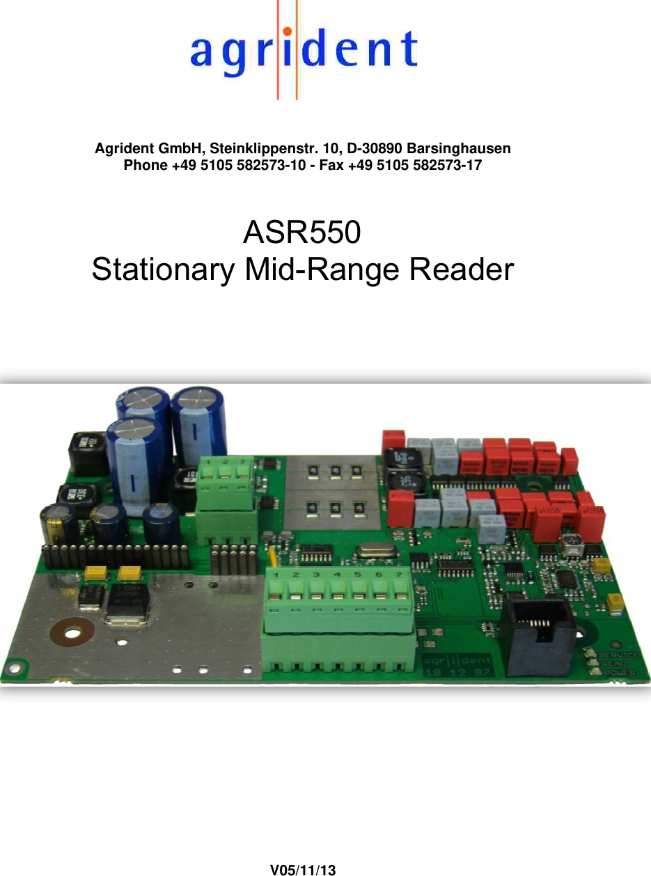
ASR550 User Manual
user manual
Navigation menu
Upload a User Manual
Namespaces
Wiki Guide
HTML
PDF
Info
Views
User Manual
Discussion / Help
Navigation
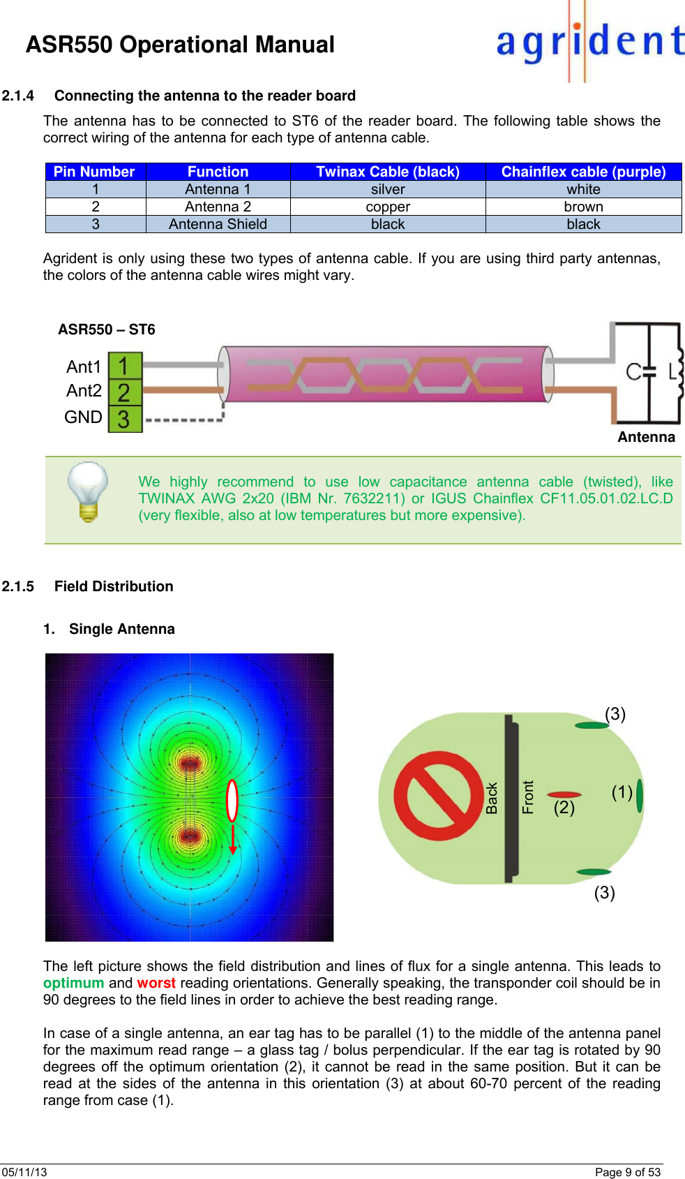
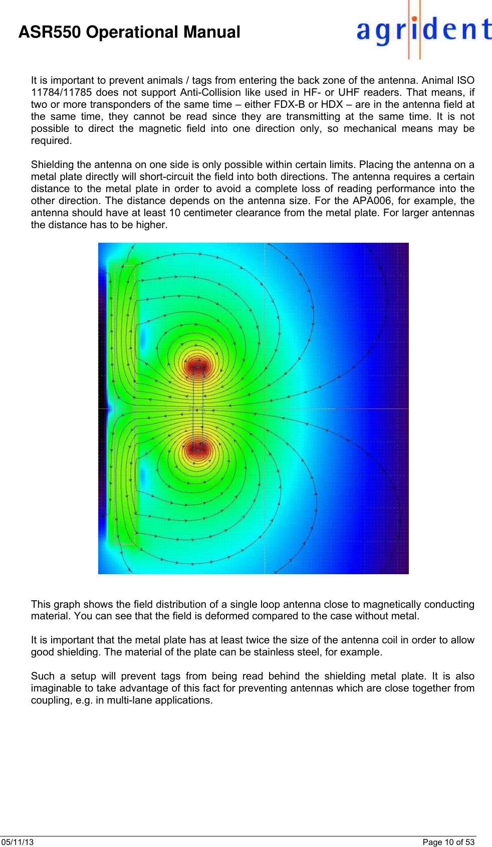
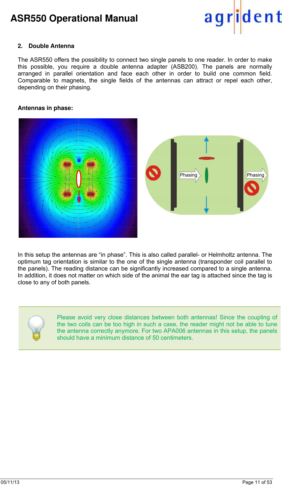
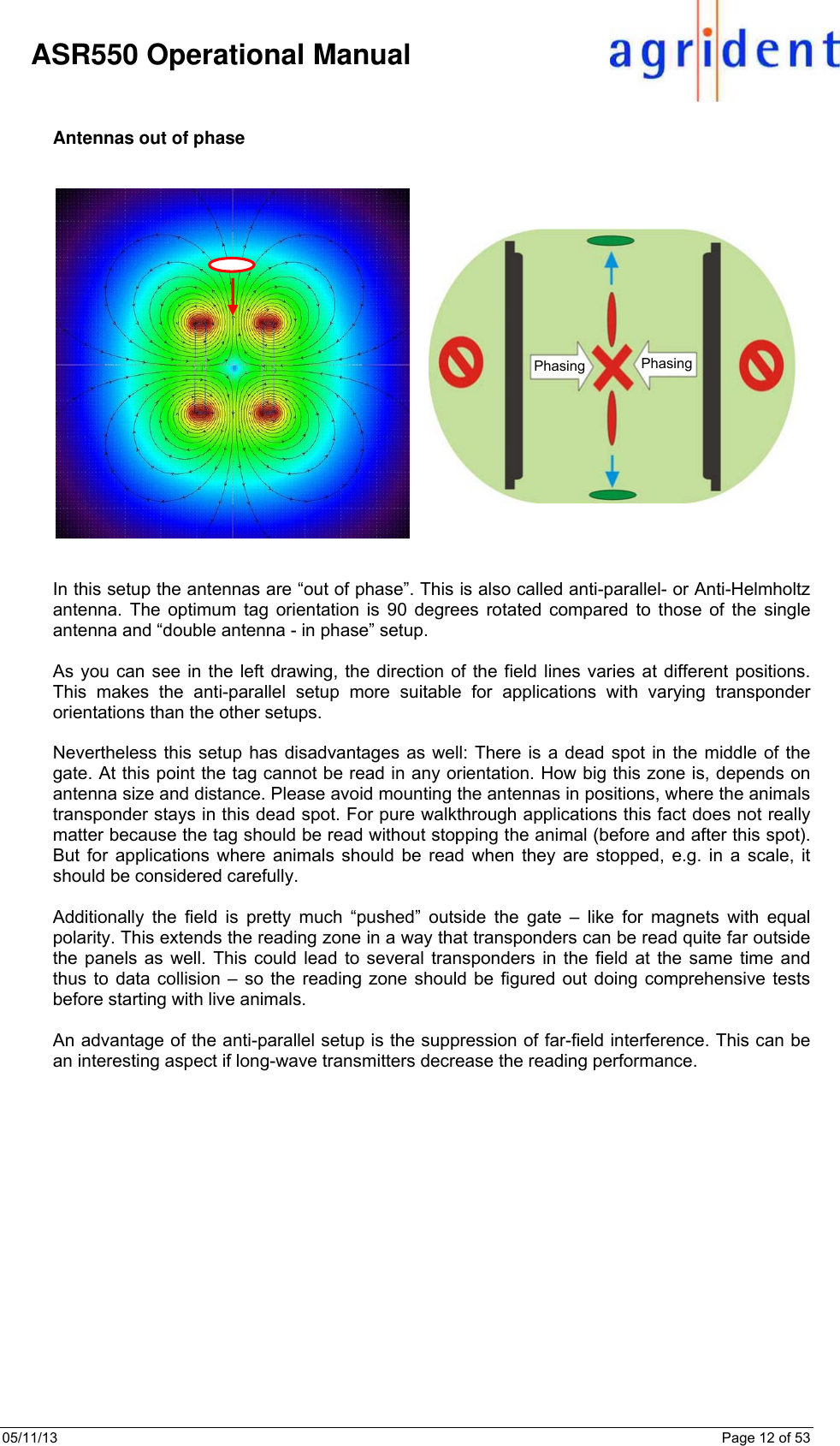
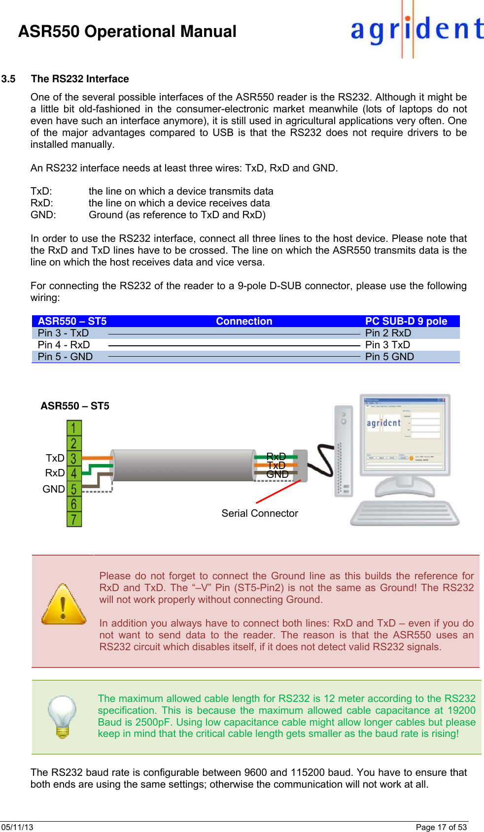
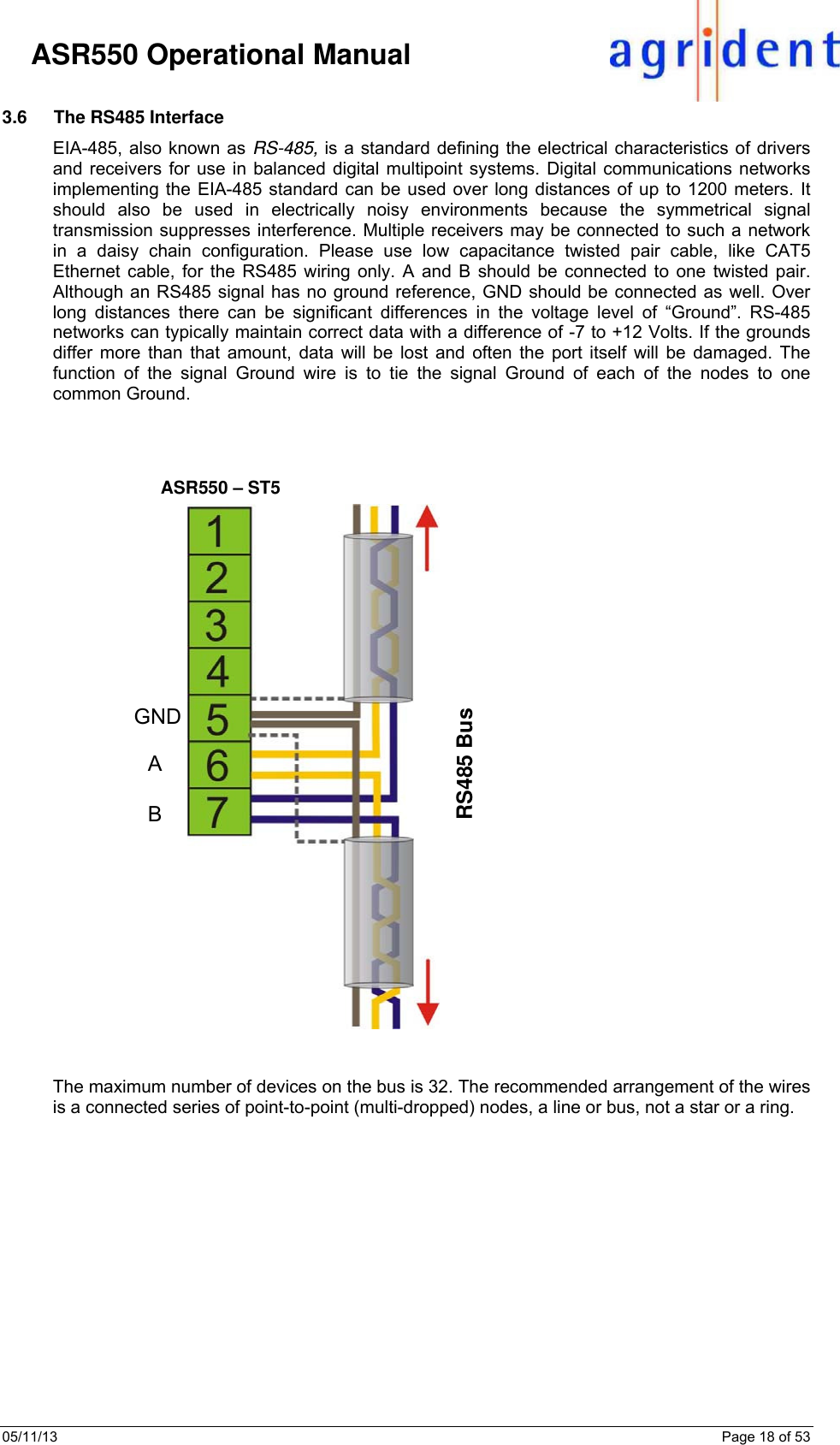
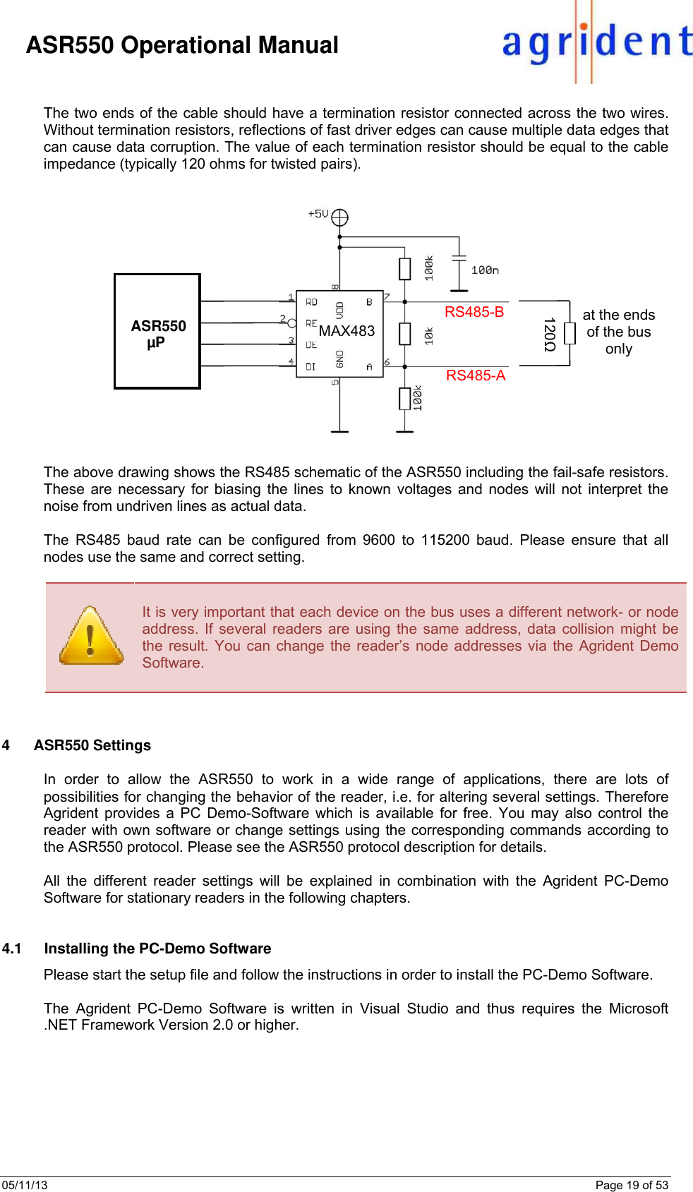
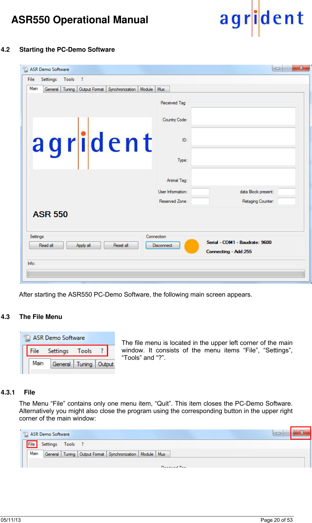
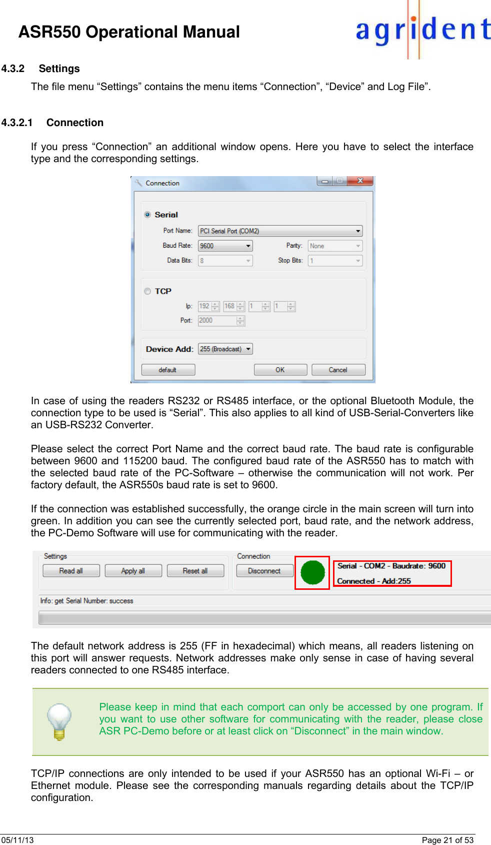
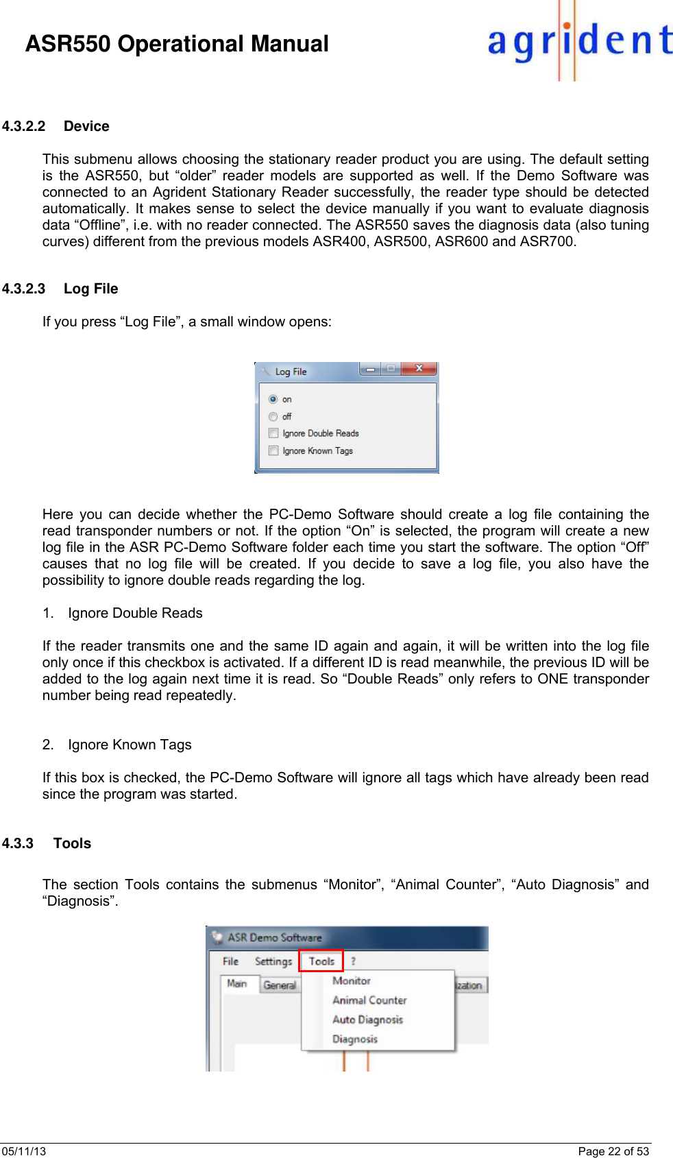
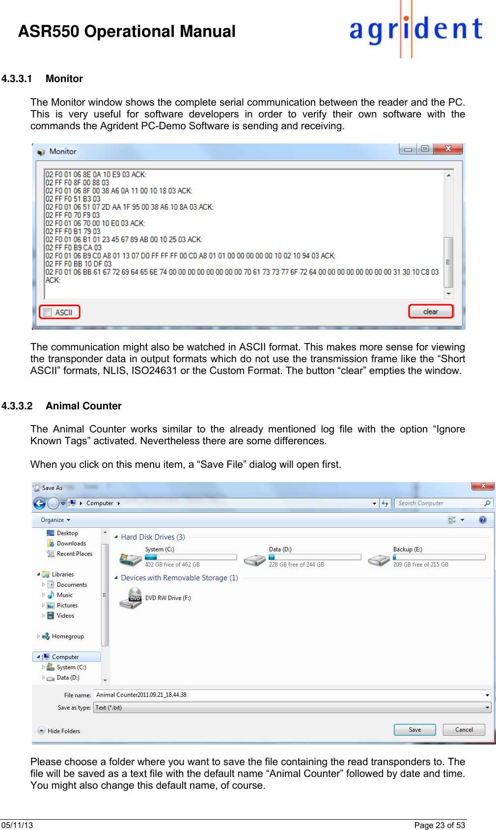
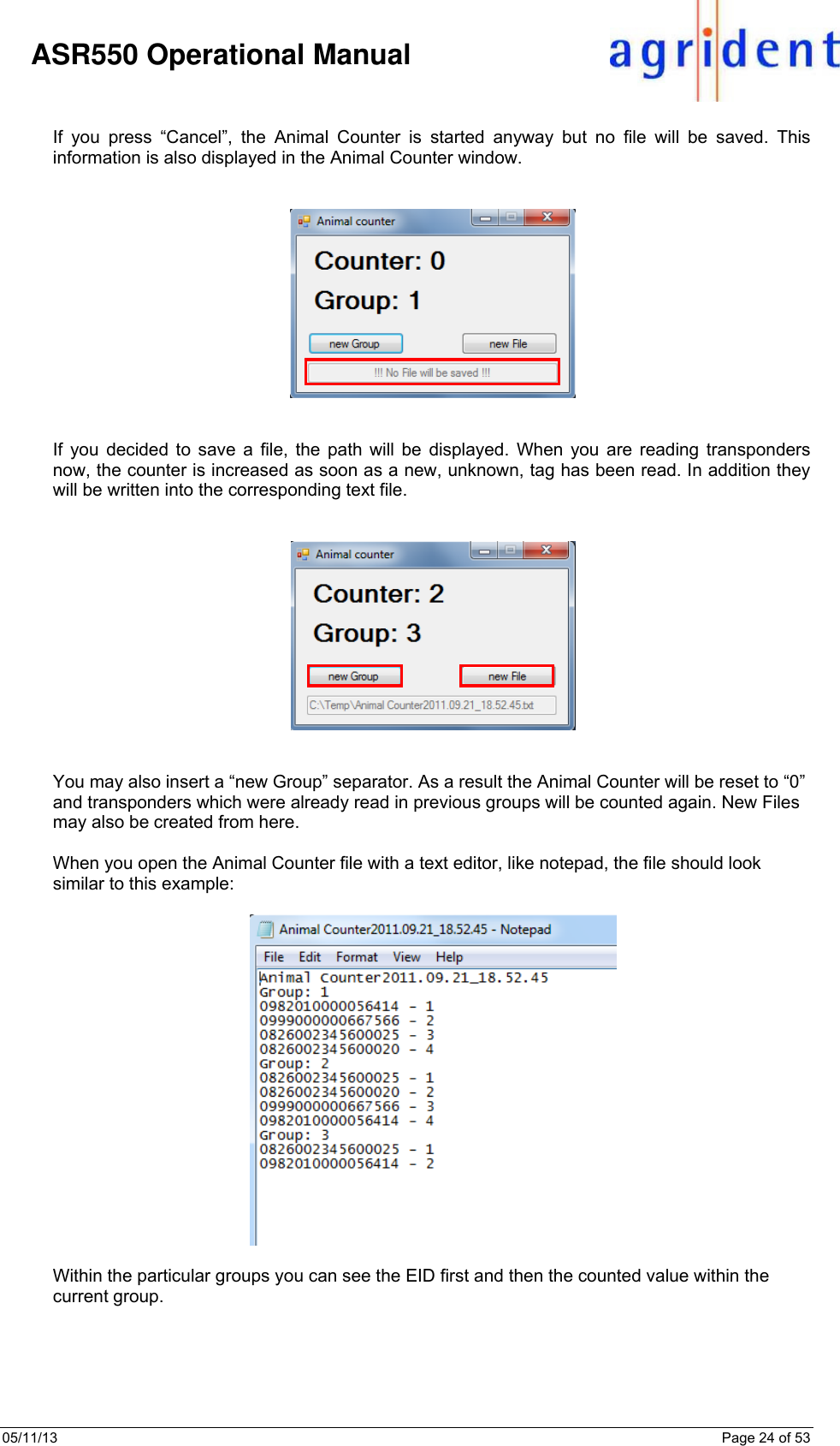
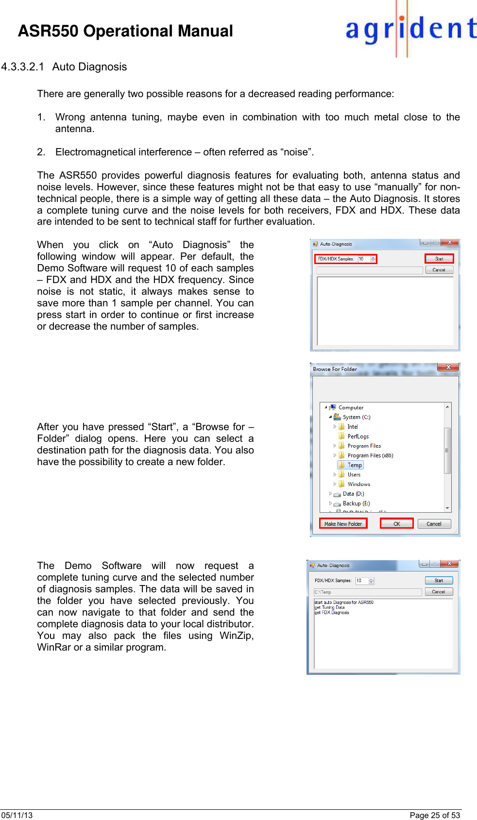
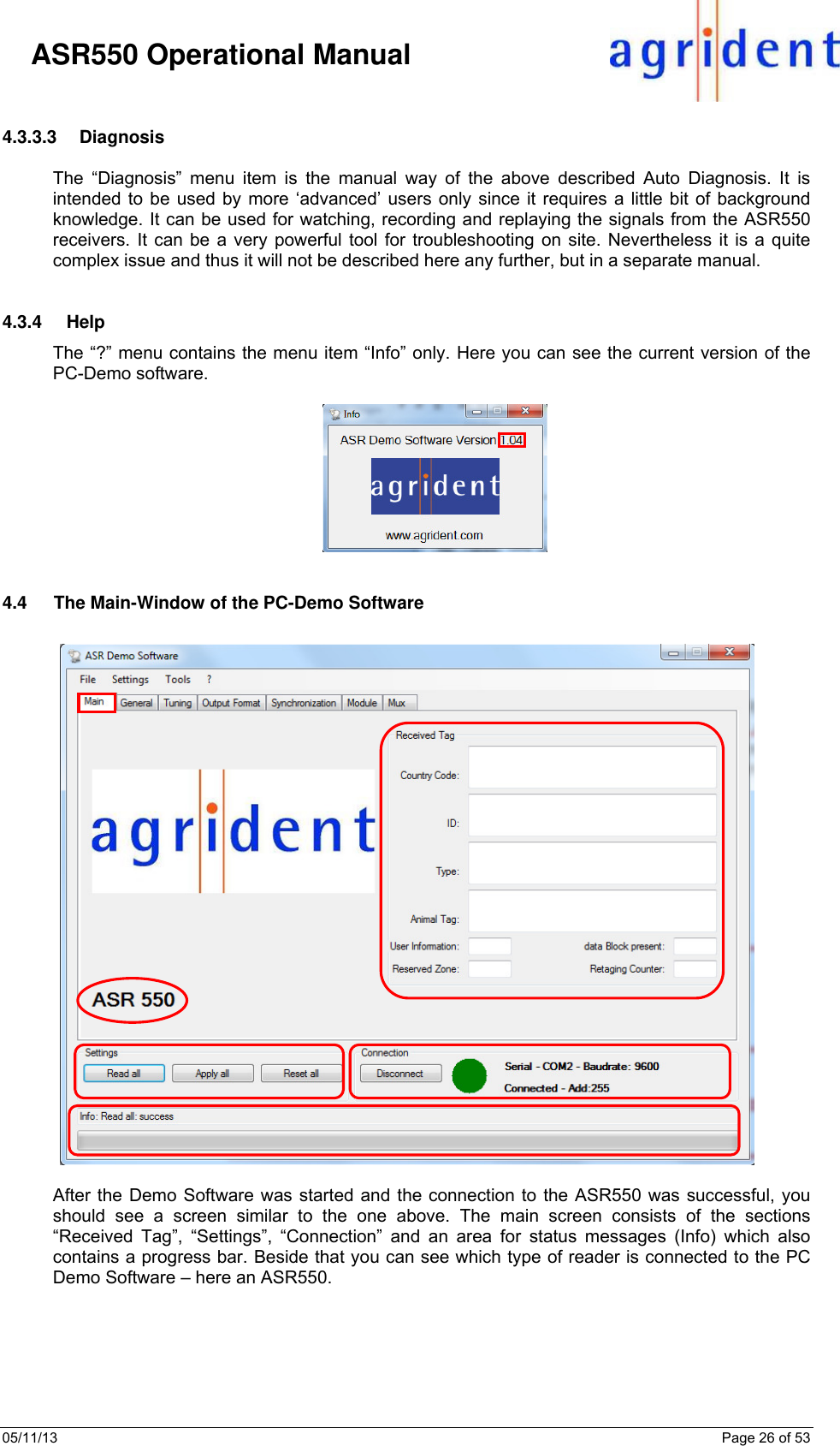
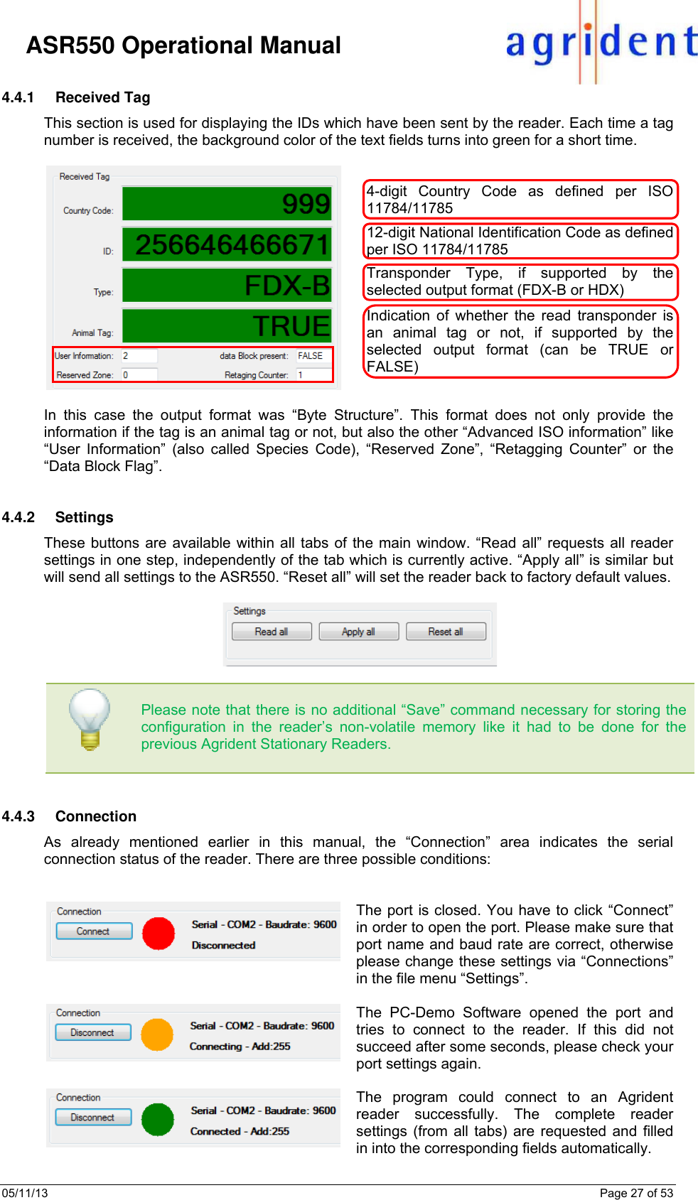
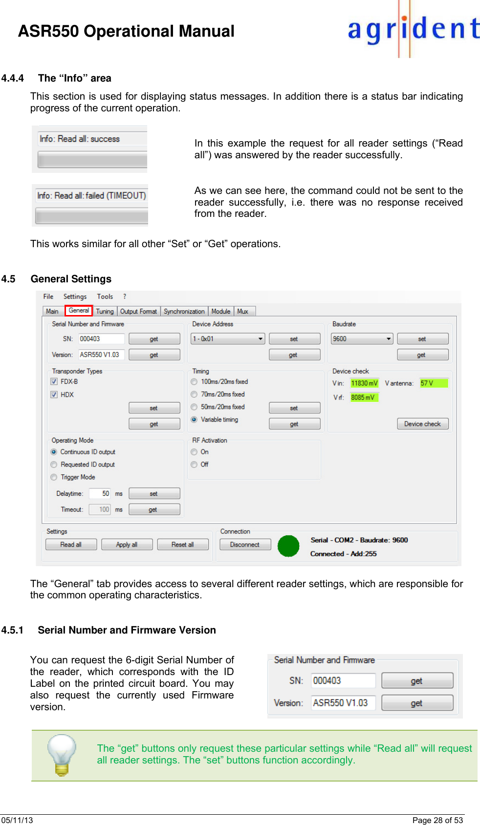
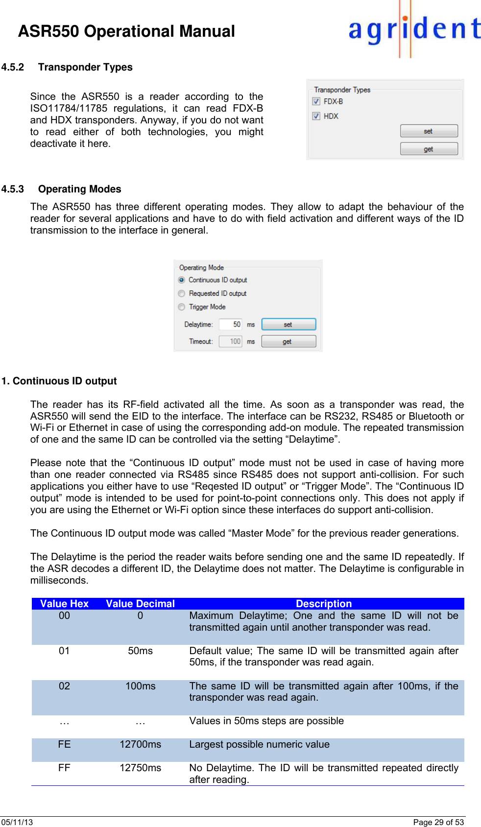
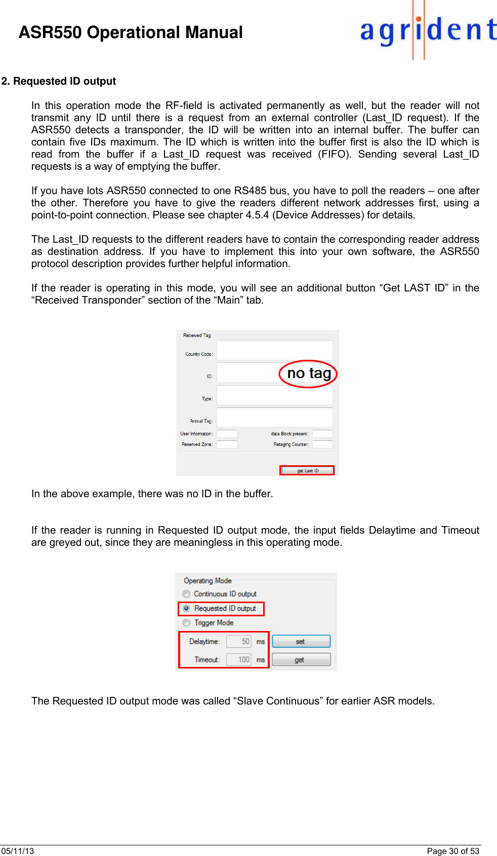
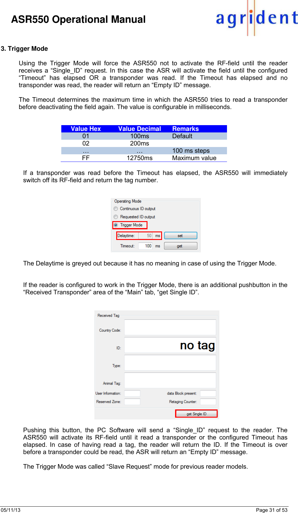
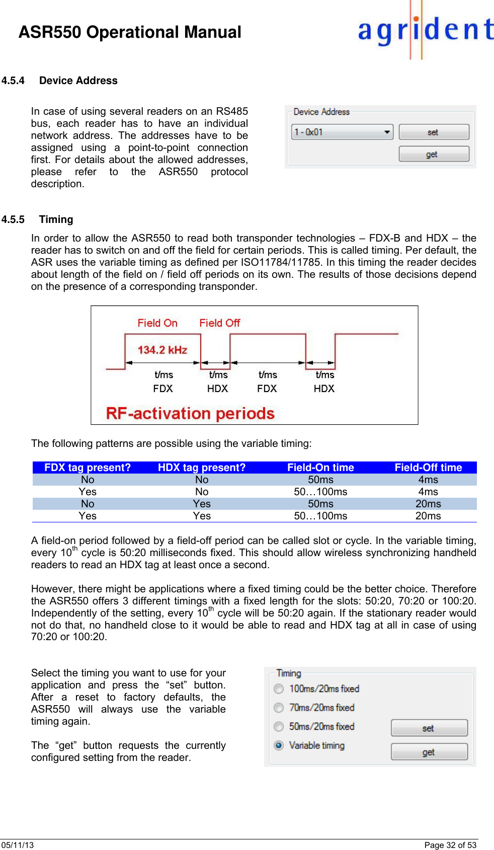
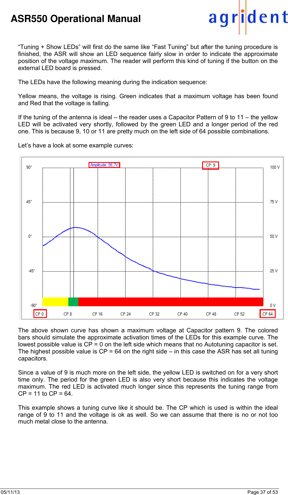
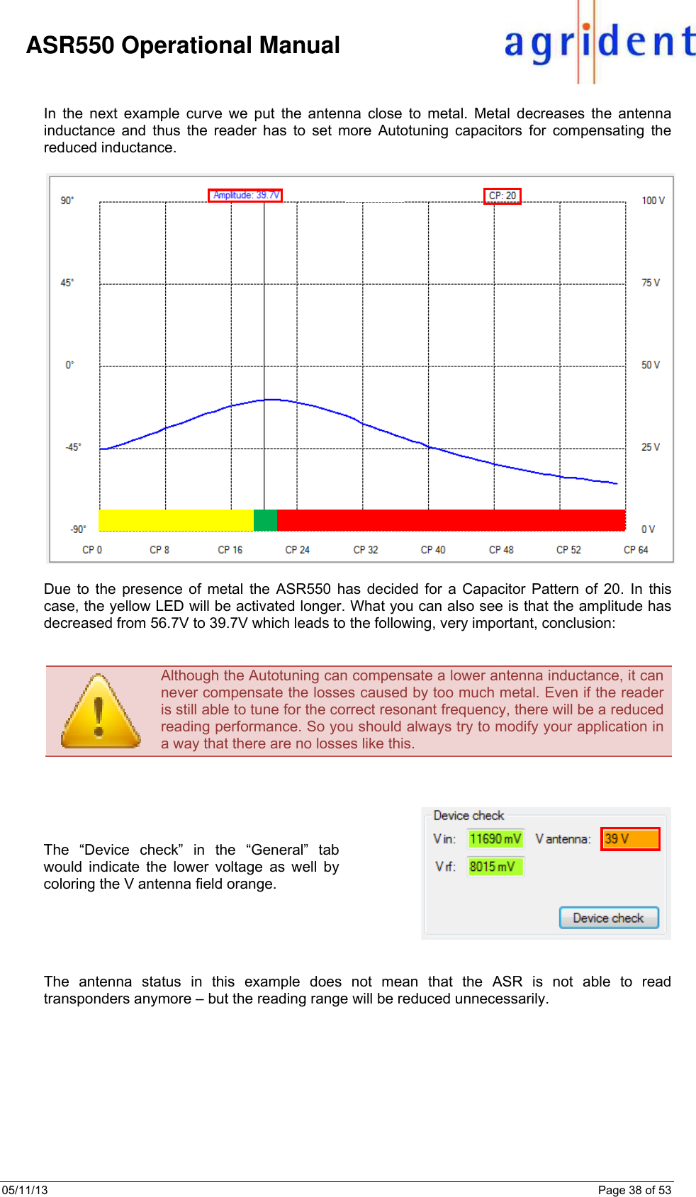
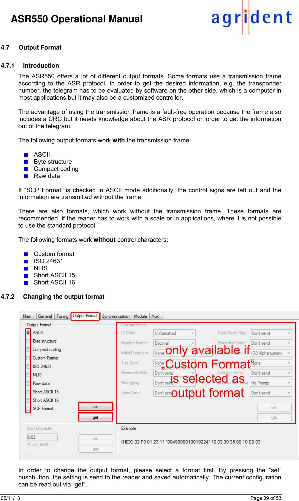
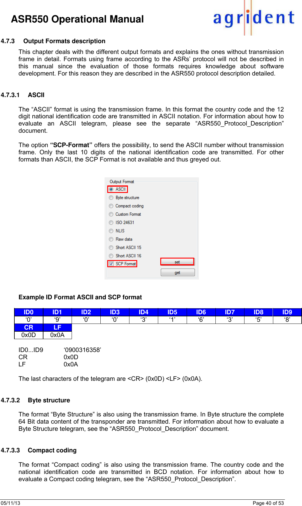
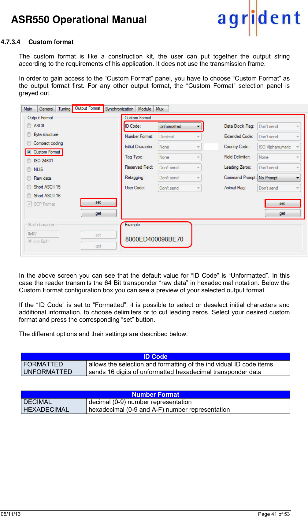
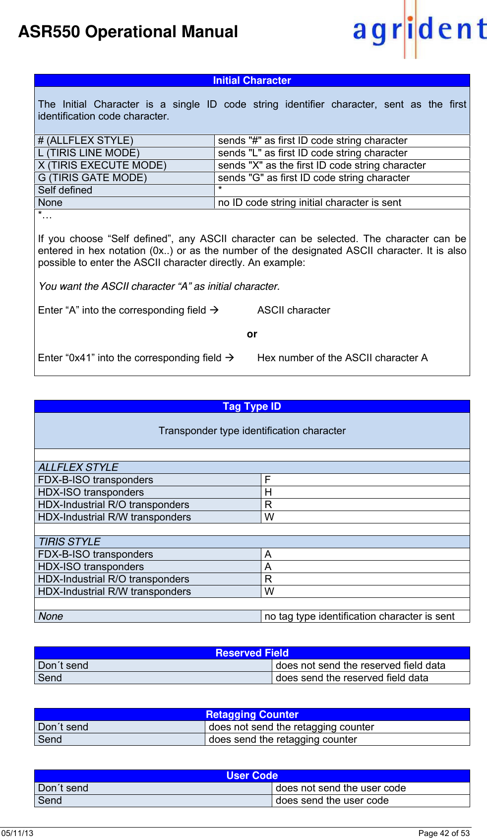
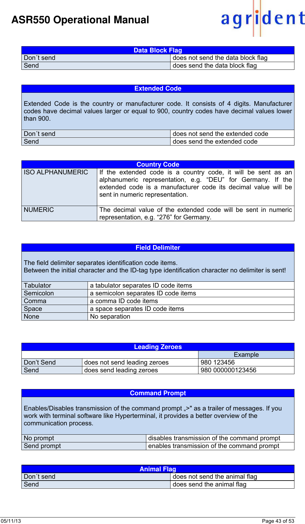
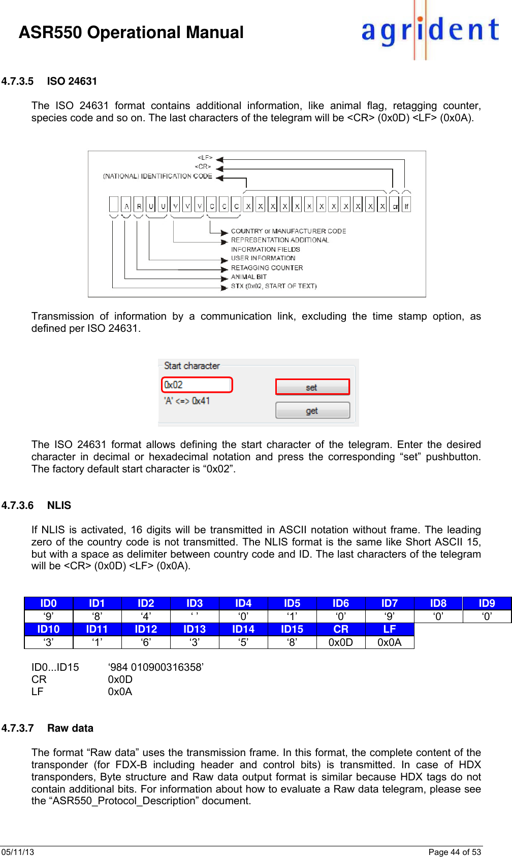
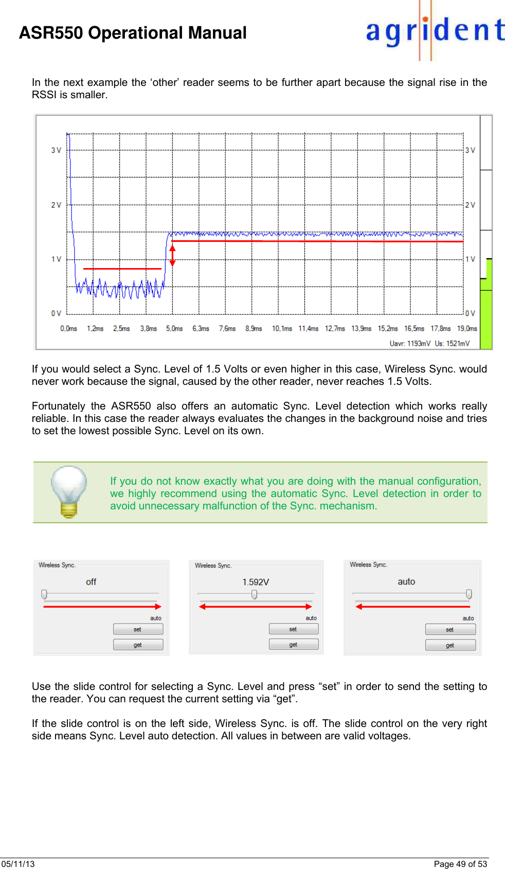
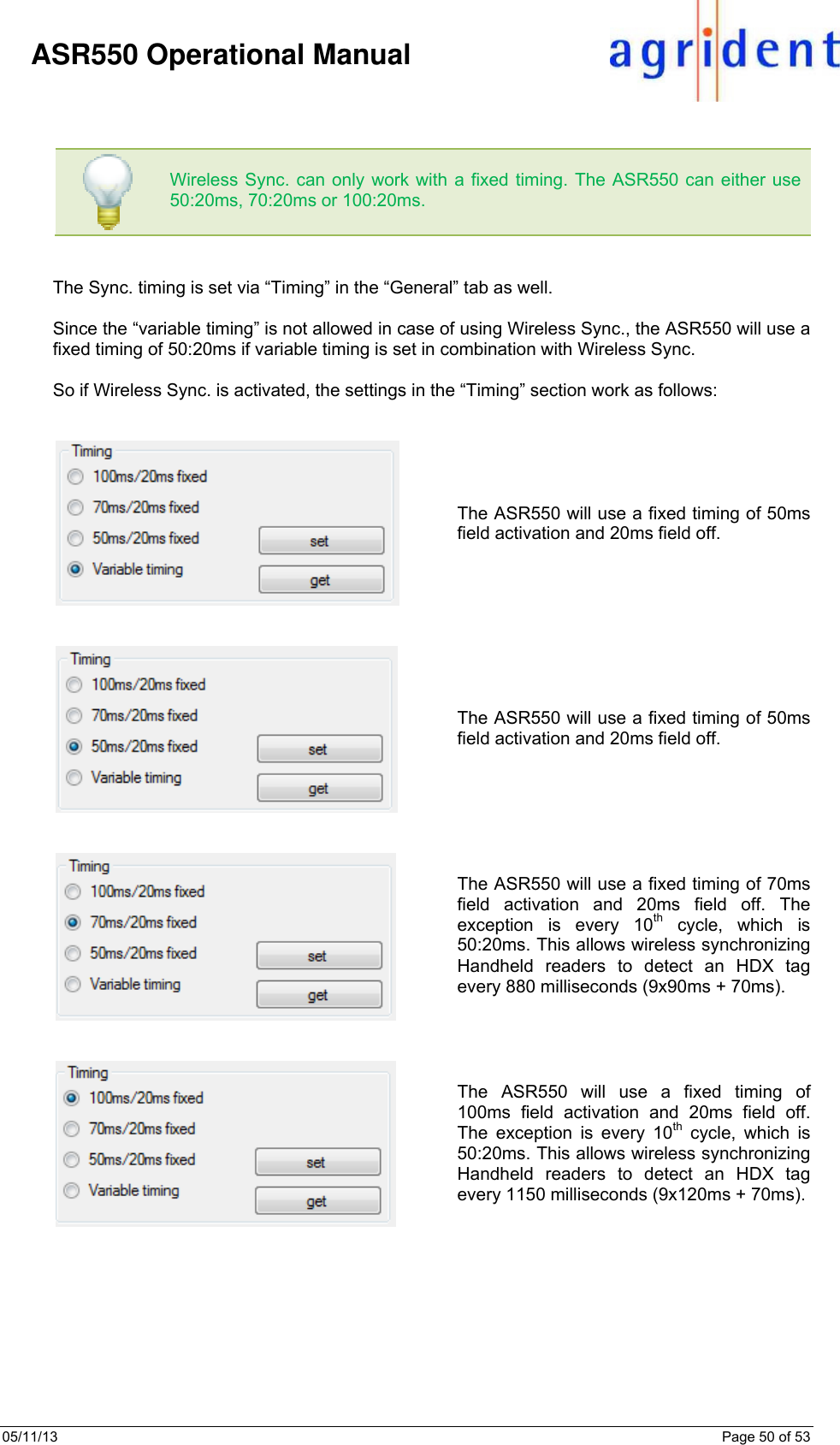
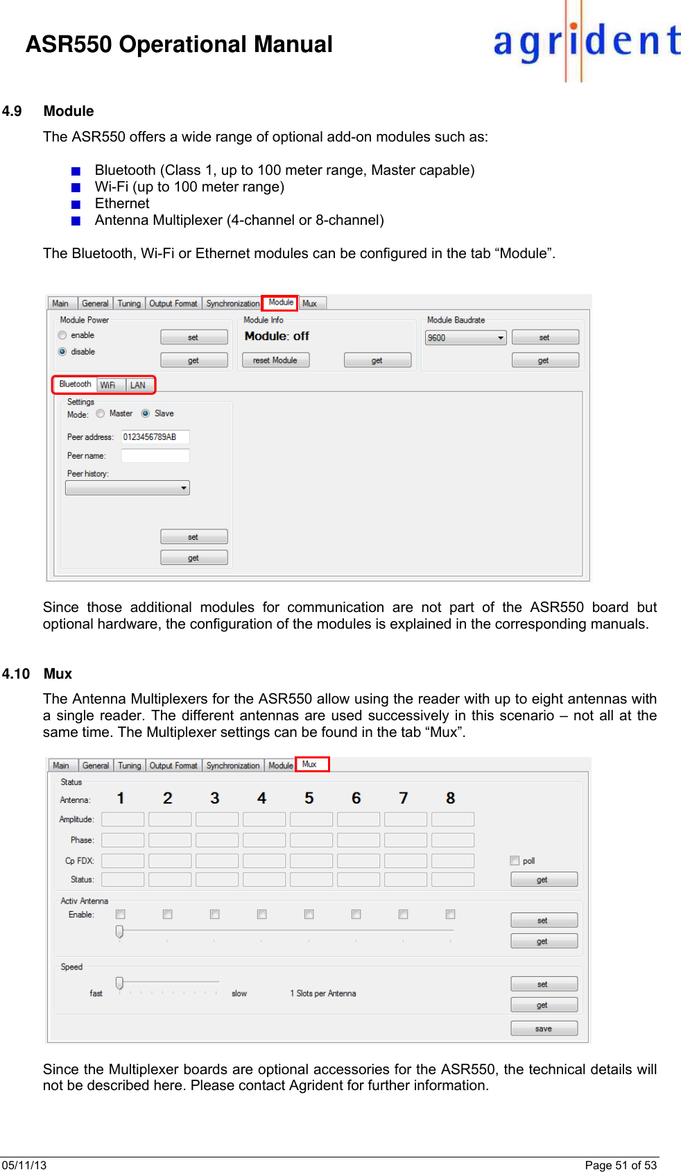
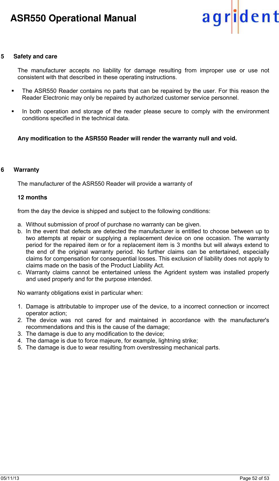
![05/11/13 Page 53 of 53 ASR550 Operational Manual 7 CE MARKING Hereby, Agrident BV declares that this equipment, if used according to the instructions, is in compliance with the essential requirements and other relevant provisions of the RTTE Directive 1999/5/EC. For use in all countries of the EU. To obtain a copy, contact Agrident BV and request the “Declaration of Conformity” document for Multi-technology readers. Agrident BV mail@agrident.com In case of alteration of the product, not agreed to by us, this declaration will lose its validity. This symbol indicates proof of conformity to applicable European Economic Community Council directives and harmonized standards published in the official journal of the European Communities. 8 FCC and IC digital device limitations FCC § 15.19 This device complies with Part 15 of the FCC rules. Operation is subject to the following two conditions: (1) This device may not cause harmful interference, and (2) this device must accept any interference received, including interference that may cause undesired operation. FCC § 15.21 (Warning Statement) [Any] changes or modifications not expressly approved by the party responsible for compliance could void the user’s authority to operate the equipment. Canada CNR-Gen Section 7.1.3 This device complies with Industry Canada licence-exempt RSS standard(s). Operation is subject to the following two conditions: (1) this device may not cause interference, and (2) this device must accept any interference, including interference that may cause undesired operation of the device. Le présent appareil est conforme aux CNR d'Industrie Canada applicables aux appareils radio exempts de licence. L'exploitation est autorisée aux deux conditions suivantes : (1) l'appareil ne doit pas produire de brouillage, et (2) l'utilisateur de l'appareil doit accepter tout brouillage radioélectrique subi, même si le brouillage est susceptible d'en compromettre le fonctionnement. 9 Trouble shooting For any problem please contact us: Agrident GmbH Steinklippenstr. 10 30890 Barsinghausen Germany Telephone +49 5105 582573-10 FAX +49 5105 582573-17 E-mail support@agrident.com](https://usermanual.wiki/Agrident/ASR550/User-Guide-2161184-Page-53.png)