Ai Thinker Technology ESP01E WiFi module User Manual
Shenzhen Ai-Thinker Technology co., LTD WiFi module
User Manual

ESP-01/07/12 Series Modules User's Manual
OEM/Integrators Installation Manual
Version 1.4
Ai-Thinker Inc
Copyright
(c)
2017

ESP-01/07/12 Series Modules User's Manual V1.4
Revision Record
Date
Version
Author
Release Notes
2017.07.01
V1.0
Wang Chong
First Version
2017.09.04
V1.1
Wang Chong
Add ESP-01M, Delete ESP-12E
2017.12.18
V1.2
Fang Dongbin
Modify the GPIO4 pin description, change
the contact number
2018.3.10
V1.3
Lv Junxiong
Add ESP-01F
2018.8.16
V1.4
Lv Junxiong
Add ESP-01E

ESP-01/07/12 Series Modules User's Manual V1.4
FCC STATEMENT
Changes or modifications not expressly approved by the party responsible for compliance
could void the user’s authority to operate the equipment.
This device complies with Part 15 of the FCC Rules. Operation is subject to the following
two conditions:
(1) this device may not cause harmful interference, and
(2) this device must accept any interference received, including interference that may cause
undesired operation.
Note: This equipment has been tested and found to comply with the limits for a Class B
digital device, pursuant to Part 15 of the FCC Rules. These limits are designed to provide
reasonable protection against harmful interference in a residential installation. This equipment
generates, uses, and can radiate radio frequency energy, and if not installed and used in
accordance with the instructions, may cause harmful interference to radio communications.
However, there is no guarantee that interference will not occur in a particular installation. If
this equipment does cause harmful interference to radio or television reception, which can be
determined by turning the equipment off and on, the user is encouraged to try to correct the
interference by one or more of the following measures:
– Reorient or relocate the receiving antenna.
– Increase the separation between the equipment and receiver.
– Connect the equipment into an outlet on a circuit different from that to which the receiver
is connected.
– Consult the dealer or an experienced radio/TV technician for help.
Please notice that if the FCC identification number is not visible when the module is
installed inside another device, then the outside of the device into which the module is installed
must also display a label referring to the enclosed module. This exterior label can use wording
such as the following: “Contains FCC ID:2AHMR-ESP01M” or “Contains FCC
ID:2AHMR-ESP07S”or “Contains FCC ID:2AHMR-ESP12S” or “Contains FCC
ID:2AHMR-ESP12F” or “Contains FCC ID:2AHMR-ESP01E”or “Contains FCC
ID:2AHMR-ESP01F”any similar wording that expresses the same meaning may be used.
This equipment complies with FCC radiation exposure limits set forth for an uncontrolled
environment. This equipment should be installed and operated with a minimum distance of 20cm
between the radiator & your body. This transmitter must not be co-located or operating in
conjunction with any other antenna or transmitter.
The module is limited to OEM installation ONLY.
The OEM integrator is responsible for ensuring that the end-user has no manual instruction t
o remove or install module.
The module is limited to installation in mobile application.
A separate approval is required for all other operating configurations, including portable con
figurations with respect to Part 2.1093 and difference antenna configurations.
There is requirement that the grantee provide guidance to the host manufacturer for complia
nce with Part 15B requirements.

ESP-01/07/12 Series Modules User's Manual V1.4
Table Of Contents
1 Product Overview .............................................................................................. 1!
1.1 Product Features ..................................................................................... 1!
1.2 Application Plan ..................................................................................... 1!
2 Module Interface ................................................................................................ 2!
2.1 Package Size ........................................................................................... 2!
2.1 Pin Definition ......................................................................................... 6!
2.2 Boot Mode .............................................................................................. 7!
3 Electrical Characteristics ................................................................................... 8!
3.1 Maximum Ratings .................................................................................. 8!
3.2 Suggested Working Environment ........................................................... 8!
3.3 Digital Port Features ............................................................................... 8!
3.4 Power Consumption ............................................................................... 8!
3.5 Transmit Power ..................................................................................... 10!
3.6 Receive Sensitivity ............................................................................... 10!
4 Hardware Guidance ......................................................................................... 11!
4.1 Typical Applications ............................................................................. 11!
4.2 PCB Antenna Display Instructions ....................................................... 13!
4.3 Module Peripheral Routing Instructions ............................................... 14!
4.4 GPIO Level Conversion ....................................................................... 15!
4.5 Power Supply Reference Design .......................................................... 15!
4.6 ADC Supply Reference Design ............................................................ 15!
4.7 Automatically Download Reference Design ........................................ 16!
4.8 Reflow oven temperature curve ............................................................ 16!
5 Usage Guide .................................................................................................... 17!
5.1 Introduction To The Basic AT Command ............................................ 17!
5.1.1 AT .............................................................................................. 17!
5.1.2 AT+GMR .................................................................................. 17!
5.1.3 AT+RST .................................................................................... 17!

ESP-01/07/12 Series Modules User's Manual V1.4
5.1.4 AT+RESTORE .......................................................................... 18!
5.2 Use Examples ....................................................................................... 18!
5.2.1 TCP Communication Test ......................................................... 18!
5.2.2 UDP Communication Test ......................................................... 20!
6 FAQ ................................................................................................................. 22!
6.1 Garbage Instructions When Power Is On ............................................. 22!
6.2 How To Shield The Power When The Garbled .................................... 22!
6.3 Can’t Burn Normally ......................................................................... 22!
6.4 SDK Development Environment .......................................................... 23!
6.5 Startup Information Description ........................................................... 23!
7 Module Selection ............................................................................................. 23!
8 Contact US ....................................................................................................... 25!

ESP-01/07/12 Series Modules User's Manual V1.4
Copyright © 2017 Shenzhen Ai-Thinker Technology Co., Ltd All Rights Reserved
Page 1 of 23
1 Product Overview
ESP8266 series wireless module is a series of cost-effective Wi-Fi SOC module
which can be developed independently. The series modules support the standard
IEEE802.11 b/g/n protocol, built-in complete TCP/IP protocol stack. Users can use
this series of modules to add networking capabilities to existing devices, or to build
standalone network controllers.
Ai-Thinker Technology can provide customers with a complete hardware,
software reference program, in order to shorten your product development cycle, for
your cost savings.
1.1 Product Features
! The smallest 802.11b/g/n Wi-Fi SOC module
! Using low-power 32-bit CPU, can also serve as the application
processor
! Clocked at up to 160MHz
! Built-in 10 bit high precision ADC
! Support UART/GPIO/IIC/PWM/ADC/HSPI and other interfaces
! Integrated Wi-Fi MAC/BB/RF/PA/LNA
! Supports multiple sleep modes, deep sleep current as low as 20uA
! Embedded Lwip protocol stack
! Support STA/AP/STA + AP work mode
! Supports Smart Config/AirKiss key distribution network
! Serial port rate up to 4Mbps
! General AT commands can be used quickly
! Support SDK secondary development
! Supports serial local upgrade and remote firmware upgrade (FOTA)
1.2 Application Plan
!Industrial wireless control
!Infant Monitor
!IP camera
!Sensor network
!Household appliances
!Home automation
!Smart socket/intelligent light
!Mesh network
!Wearable electronic products
!Wireless location sensing device
!Security ID tag
!Wireless positioning system beacon
ESP-01/07/12 Series Modules User's Manual V1.4
Copyright © 2017 Shenzhen Ai-Thinker Technology Co., Ltd All Rights Reserved
Page 2 of 23
2 Module Interface
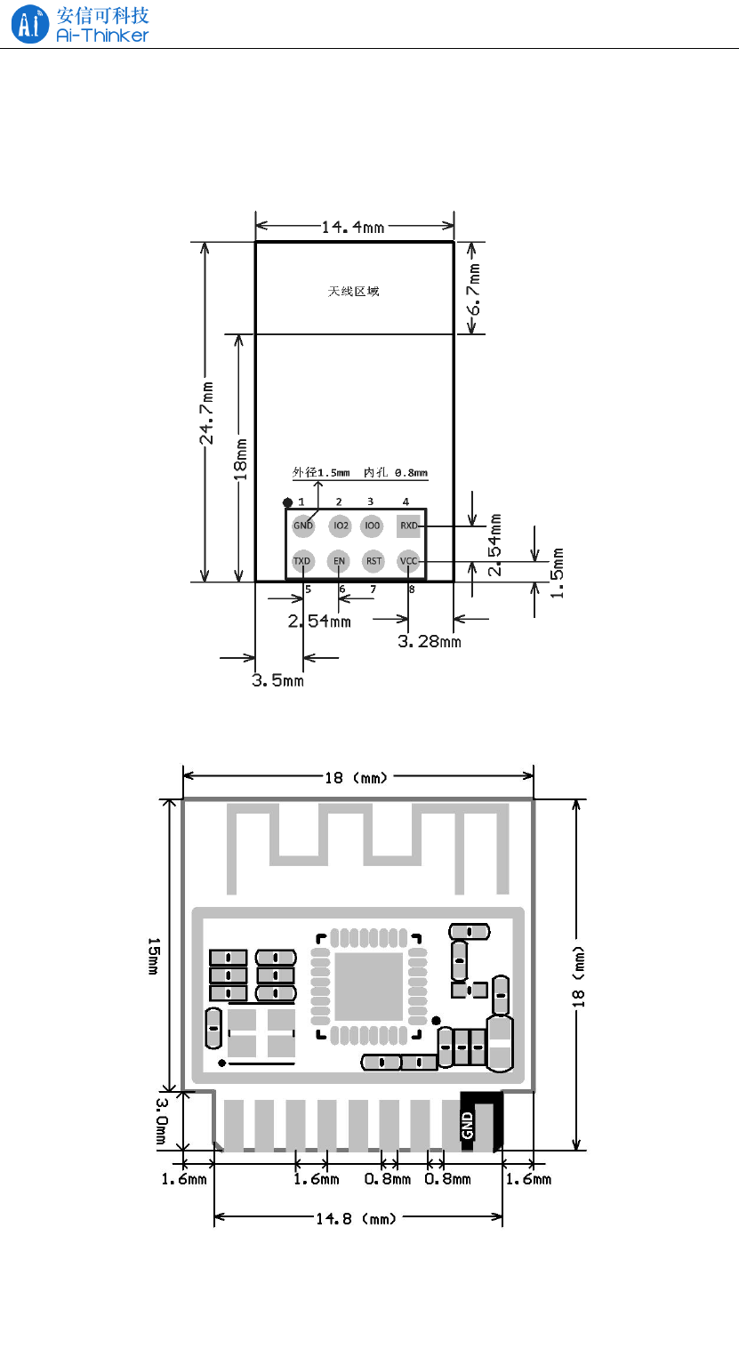
2.1 Package Size
Figure 2.1 ESP-01/ESP-01S pin dimensions
Figure 2.2 ESP-01M pin dimensions
ESP-01/07/12 Series Modules User's Manual V1.4
Copyright © 2017 Shenzhen Ai-Thinker Technology Co., Ltd All Rights Reserved
Page 3 of 23
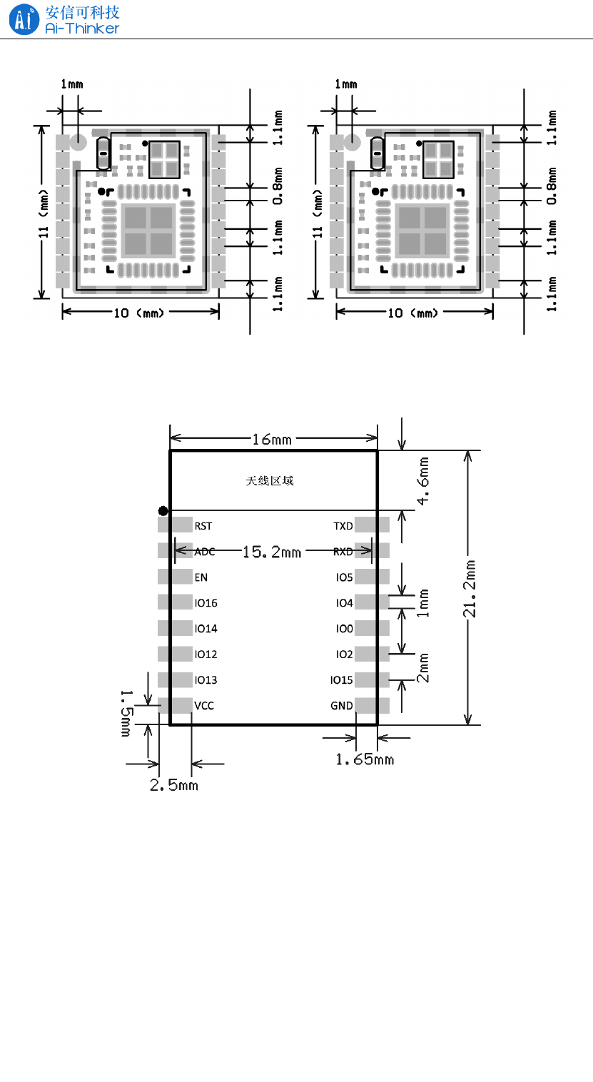
Figure 2.3 ESP-01F pin dimensions
Figure 2.4 ESP-07 pin dimensions
ESP-01/07/12 Series Modules User's Manual V1.4
Copyright © 2017 Shenzhen Ai-Thinker Technology Co., Ltd All Rights Reserved
Page 4 of 23
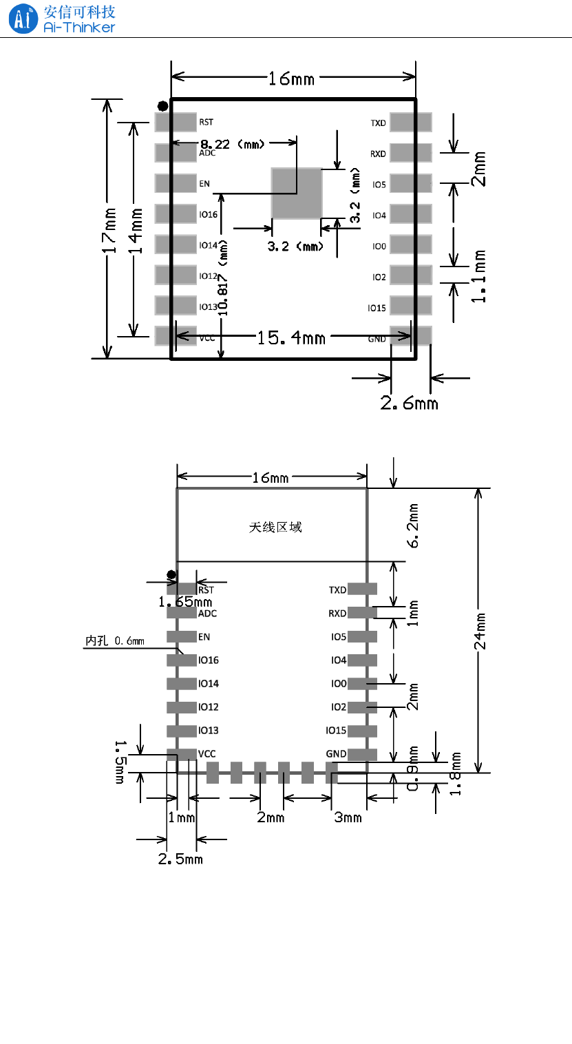
Figure 2.5 ESP-07S pin dimensions
Figure 2.6 ESP-12F pin dimensions
ESP-01/07/12 Series Modules User's Manual V1.4
Copyright © 2017 Shenzhen Ai-Thinker Technology Co., Ltd All Rights Reserved
Page 5 of 23
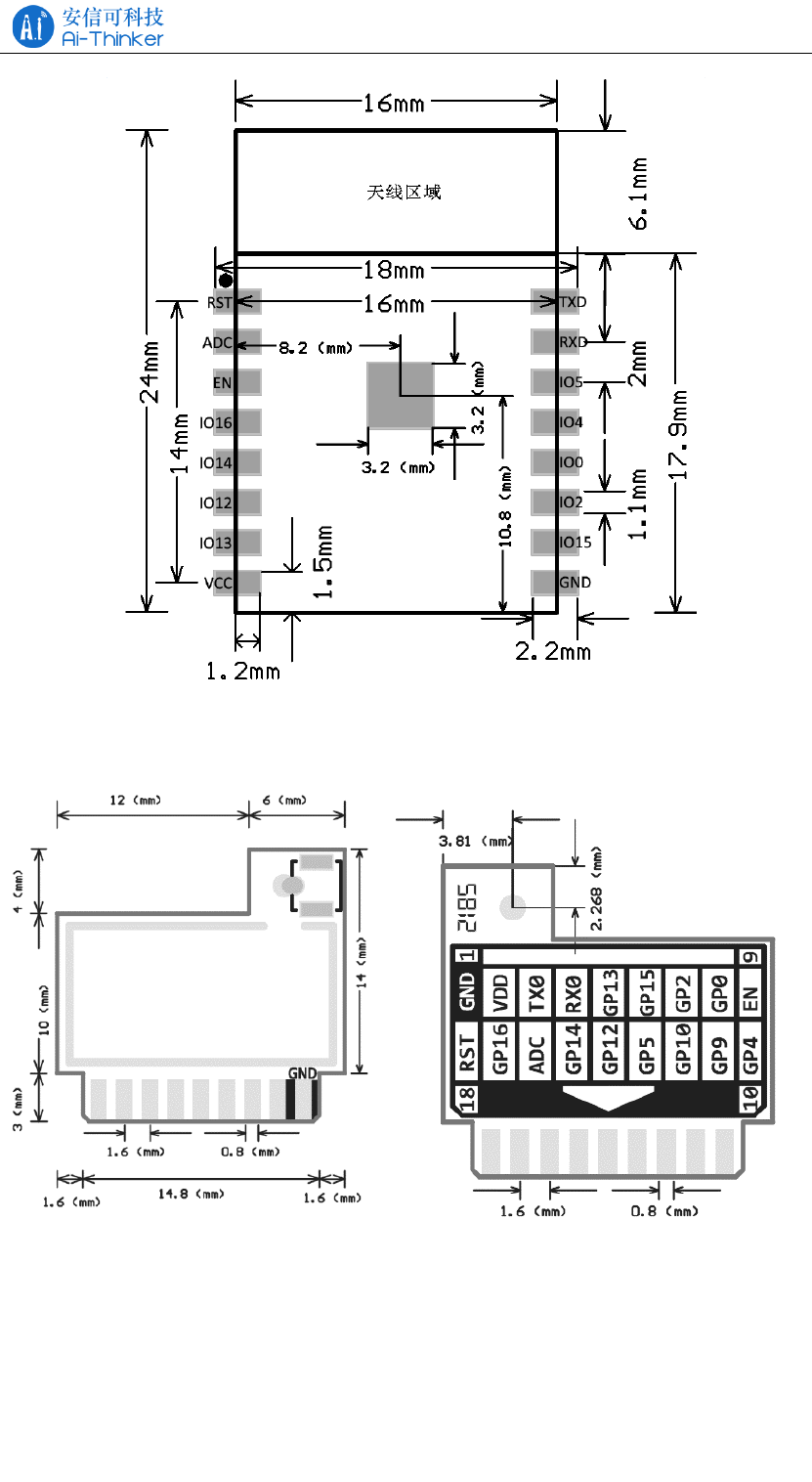
Figure 2.7 ESP-12S pin dimensions
Figure 2.7 ESP-01E pin dimensions

ESP-01/07/12 Series Modules User's Manual V1.4
Copyright © 2017 Shenzhen Ai-Thinker Technology Co., Ltd All Rights Reserved
Page 6 of 23
Table 2.1 ESP series module size table
Model
Length
(mm)
Width
(mm)
Height
(mm
PAD size
(mm)
Pin
Spacing
(mm)
Shield
ed
Shell
(mm)
Thickness
(mm)
ESP-01
ESP-01S
24.7
14.4
11.0
1.5 x 1.5
2.54
-
1.0±0.1
ESP-01M
18
18
2.8±0.2
-
1.6
2.0
0.8±0.1
ESP-01F
11
10
2.0±0.2
1.1
1.2
0.8±0.1
ESP-07
21.2
16.0
3.0±0.2
-
2.0
2.0
0.8±0.1
ESP-07S
17.0
16.0
3.0±0.3
1 x 1.2
2.0
2.0
0.8±0.1
ESP-12F
24.0
16.0
3.0±0.2
2.0
2.0
0.8±0.1
ESP-12S
24.0
16.0
3.0±0.2
1 x 1.2
2.0
2.0
0.8±0.1
2.1 Pin Definition
Table 2.2 ESP Series Module Pin Function Definitions
Pin Number
Pin
Nam
e
Remarks
01
01S
01M
01E
01F
07
07S
12S
12F
7
18
18
16
1
1
RST
Reset Pin, Active Low
-
16
16
3
2
2
ADC
AD conversiont, Input voltage
range 0~1V, the value range is
0~1024.
6
9
9
4
3
3
EN
Chip Enabled Pin, Active High
-
17
17
5
4
4
IO16
Connect with RST pin to wake
up Deep Sleep
-
15
15
6
5
5
IO14
HSPI_CLK,IR_T,I2C_SCL
,I2SI_WS
-
14
14
7
6
6
IO12
HSPI_MISO
-
5
5
8
7
7
IO13
HSPI_MOSI; UART0_CTS
8
2
2
17
8
8
VCC
Module power supply pin, the
voltage range of 3.0 ~ 3.6V
-
-
-
-
-
9
CS0
Flash chip select signal
-
-
-
-
-
10
MIS
O
Slave Output Master Input
-
11
11
-
-
11
IO9
Gpio9,Only ESP-01M/01E Can

ESP-01/07/12 Series Modules User's Manual V1.4
Copyright © 2017 Shenzhen Ai-Thinker Technology Co., Ltd All Rights Reserved
Page 7 of 23
-
12
12
-
-
12
IO10
Gpio10,Only ESP-01M/01E Can
-
-
-
-
-
13
MOS
I
Master Output Slave Input
-
-
-
-
-
14
SCL
K
Clock
1
1
1
2/18
9
15
GND
GND
-
6
6
9
10
16
IO15
HSPI_CS,U0_RTS,
I2SO_BCK
2
7
7
10
11
17
IO2
U1_TXD,I2C_SDA,I2SO_WS
3
8
8
11
12
18
IO0
GPIO0,HSPI_MISO,
I2SI_DATA
-
10
10
12
13
19
IO4
GPIO4
-
13
13
13
14
20
IO5
IR_R
4
4
4
14
15
21
RXD
GPIO3,I2SO_DATA
5
3
3
15
16
22
TXD
GPIO1
-
-
1
1
-
-
ANT,Only ESP-01F/01E Can
Note: Only GPIO4 and GPIO5 are low at boot time, the other GPIO are high.
2.2 Boot Mode
Table 2.3 Description of the ESP series module boot mode
Mode
CH_PD
(EN)
RST
GPIO15
GPIO0
GPIO2
TXD0
Download
mode
high
high
low
low
high
high
Running
mode
high
high
low
high
high
high
Chip Test
mode
high
high
-
-
-
low

ESP-01/07/12 Series Modules User's Manual V1.4
Copyright © 2017 Shenzhen Ai-Thinker Technology Co., Ltd All Rights Reserved
Page 8 of 23
3 Electrical Characteristics
3.1 Maximum Ratings
Table 3.1 Maximum Ratings
Rated value
condition
Value
Unit
Storage Temperature
-
-40 ~ 90
℃
Maximum Welding
Temperature
-
250
℃
Supply Voltage
IPC/JEDEC
J-STD-020
+3.0 ~ +3.6
V
3.2 Suggested Working Environment
Table 3.2 Recommended working environment
Work Environment
Name
Min
Typ
Max
Unit
Operating Temperature
-20
20
85
℃
Supply Voltage
VDD
3.0
3.3
3.6
V
3.3 Digital Port Features
Table 3.3 Digital Port Features
Port
Name
Min
Typ
Max
Unit
Input logic level low
VIL
-0.3
-
0.25 * VDD
V
Input logic level high
VIH
0.75 * VDD
-
VDD + 0.3
V
Output logic level low
VOL
N
-
0.1 * VDD
V
Output logic level
high
VOH
0.8 * VDD
-
N
V
Note: Unless otherwise specified, the test conditions are: VDD = 3.3 V and
temperature 20 ℃.
3.4 Power Consumption
All measurements are made at the antenna interface without SAW filters.

ESP-01/07/12 Series Modules User's Manual V1.4
Copyright © 2017 Shenzhen Ai-Thinker Technology Co., Ltd All Rights Reserved
Page 9 of 23
All transmit data is based on a 90% duty cycle measured in the continuous firing
mode.
Table 3.4 Power consumption
Mode
Min
Ty
p
Ma
x
Unit
Transmit 802.11b, CCK 11Mbps, POUT = +
17dBm
170
mA
Transmit 802.11g, OFDM 54Mbps, POUT = +
15dBm
140
mA
Transmit 802.11n, MCS7, POUT = + 13dBm
120
mA
Receive 802.11b, packet length 1024 bytes,
-80dBm
50
mA
Receive 802.11g, packet length 1024 bytes,
-70dBm
56
mA
Receive 802.11n, packet length 1024 bytes,
-65dBm
56
mA
Modem-Sleep①
20
mA
Light-Sleep②
2
mA
Deep-Sleep③
20
uA
Power Off
1
uA
Note: Modem-Sleep is used to require the CPU to remain in operation, such as PWM or I2S.
When there is no data transmission while maintaining a WiFi connection, power off the WiFi
Modem circuit according to the 802.11 standard (eg U-APSD). For example, in DTIM3, every
sleep 300mS, wake up 3mS receive AP Beacon package, etc., the overall average current of about
20mA.
Note ②: Light-Sleep for CPU can be suspended applications, such as WiFi switch. If there
is no data transmission while maintaining a WiFi connection, the WiFi Modem circuit can be
switched off and the CPU is powered down according to the 802.11 standard (eg U-APSD). For
example, at DTIM3, every sleep 300 ms, wake up 3 ms to receive AP's Beacon packets, etc., the
overall average current is about 2 mA.
Note: Deep-Sleep is used for applications that do not have to keep the WiFi connection for a
long time, such as a sensor that measures the temperature once every 100 seconds. Every 300 s
wake up after 0.3s - 1s connected to the AP to send data, the overall average current can be much
smaller than 2mA.

ESP-01/07/12 Series Modules User's Manual V1.4
Copyright © 2017 Shenzhen Ai-Thinker Technology Co., Ltd All Rights Reserved
Page 10 of
23
3.5 Transmit Power
Table 3.5 RF parameters
Describe
Min
Typ
Max
Unit
802.11b@11Mbps
14
16
18
dBm
802.11g@54Mbps
12
14
16
dBm
802.11n@HT20, MCS7
11
13
15
dBm
3.6 Receive Sensitivity
Table 3.6 Receiving Sensitivity
Parameter
Min
Typ
Max
Unit
DSSS, 1 Mbps
-95
dBm
CCK, 11 Mbps
-80
dBm
6 Mbps (1/2 BPSK)
-88
dBm
54 Mbps (3/4 64-QAM)
-70
dBm
HT20, MCS7 (65 Mbps, 72.2 Mbps)
-67
dBm
ESP-01/07/12 Series Modules User's Manual V1.4
Copyright © 2017 Shenzhen Ai-Thinker Technology Co., Ltd All Rights Reserved
Page 11 of
23
4 Hardware Guidance
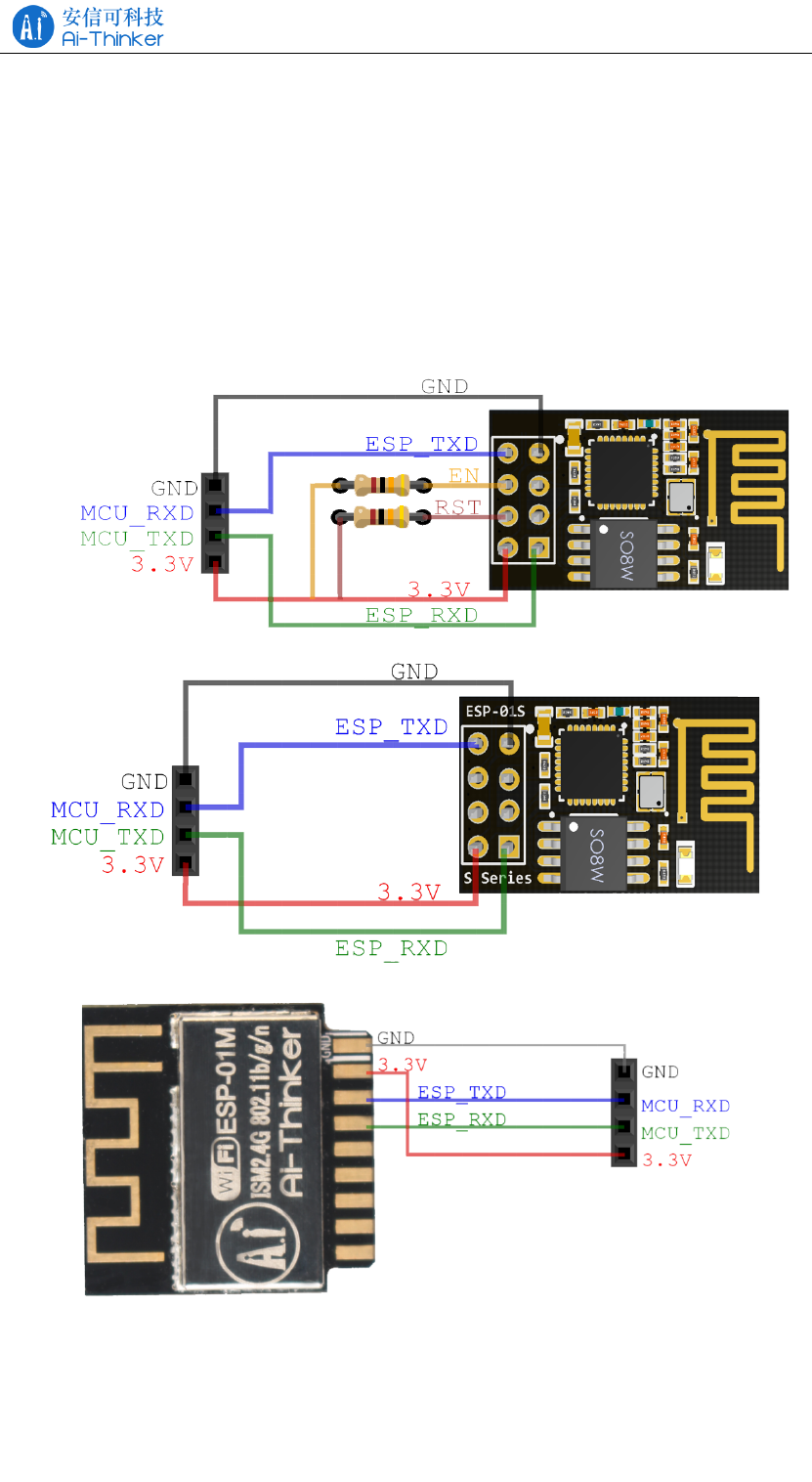
4.1 Typical Applications
Note: You can’t use USB to TTL 3.3V or 5V power supply, it is recommended
to use two dry batteries or after conversion through the LDO 3.3V, it is strongly
recommended to buy a new development board.
Figure 4.1 Typical application of ESP-01
Figure 4.2 Typical application of ESP-01S
Figure 4.3 Typical application of ESP-01M
ESP-01/07/12 Series Modules User's Manual V1.4
Copyright © 2017 Shenzhen Ai-Thinker Technology Co., Ltd All Rights Reserved
Page 12 of
23
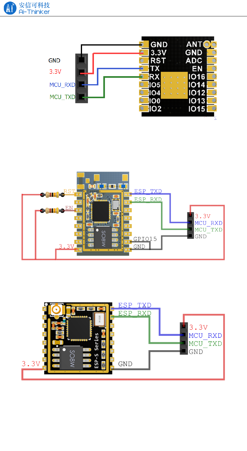
Figure 4.4 Typical application of ESP-01F
Figure 4.5 Typical application of ESP-07
Figure 4.6 Typical application of ESP-07S
ESP-01/07/12 Series Modules User's Manual V1.4
Copyright © 2017 Shenzhen Ai-Thinker Technology Co., Ltd All Rights Reserved
Page 13 of
23
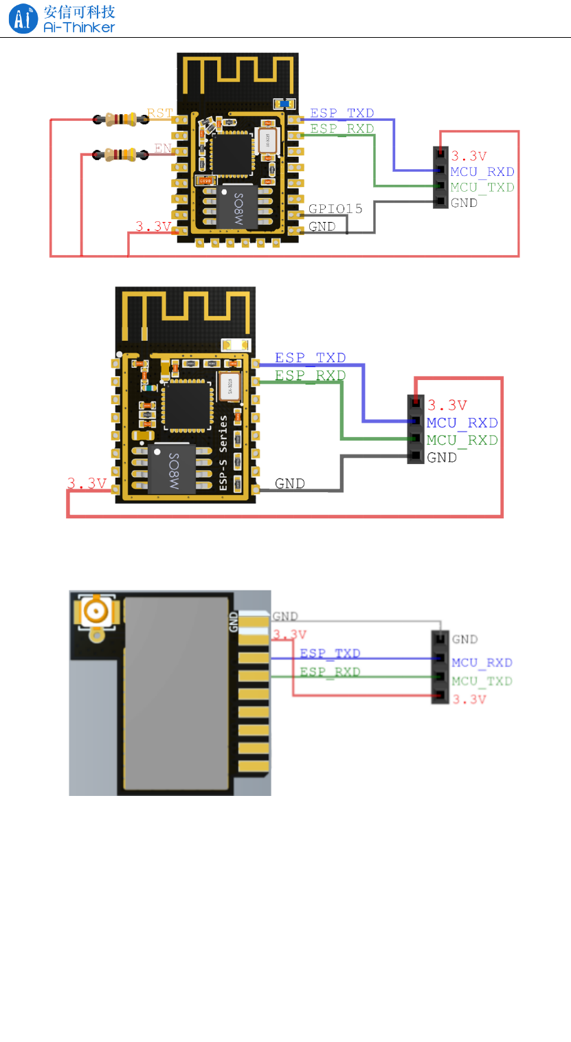
Figure 4.7 Typical application of ESP-12E/ESP-12F
Figure 4.8 Typical application of ESP-12S
Figure 4.9 Typical application of ESP-01E
4.2 PCB Antenna Display Instructions
The ESP8266 series module can be soldered to the PCB board. In order to get
the best RF performance of the end product, please pay attention to the rational
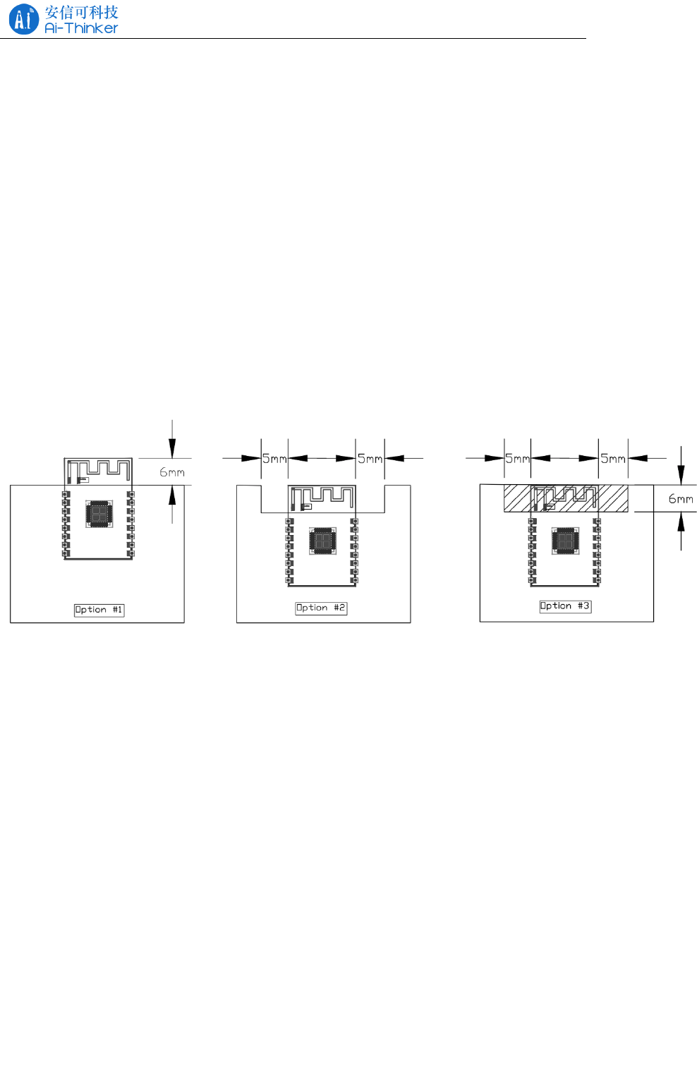
ESP-01/07/12 Series Modules User's Manual V1.4
Copyright © 2017 Shenzhen Ai-Thinker Technology Co., Ltd All Rights Reserved
Page 14 of
23
design of the module and the placement of the antenna on the bottom plate according
to this guide.
Option 1 (recommended):
Place the module along the edge of the PCB board, and the antenna is placed
outside the frame or along the board and the bottom is hollowed out;
Option 2:
The module placed along the PCB board side, the antenna placed along the
board and the bottom of the hollow;
Option 3:
Place the module along the board side of the board, the antenna placed along the
board and the bottom are not copper.
Figure 4.7 ESP-12S antenna placement instructions
4.3 Module Peripheral Routing Instructions
The ESP8266 series modules integrates high-speed GPIO and peripheral
interfaces, which can cause severe switching noise. If some applications require high
power and EMI characteristics, it is recommended to connect 10 to 100 ohms in
series on digital I/O lines. This can suppress overshoot when switching power
supplies and make the signal smooth. Series resistance can also prevent electrostatic
discharge (ESD) to some extent.
ESP-01/07/12 Series Modules User's Manual V1.4
Copyright © 2017 Shenzhen Ai-Thinker Technology Co., Ltd All Rights Reserved
Page 15 of
23
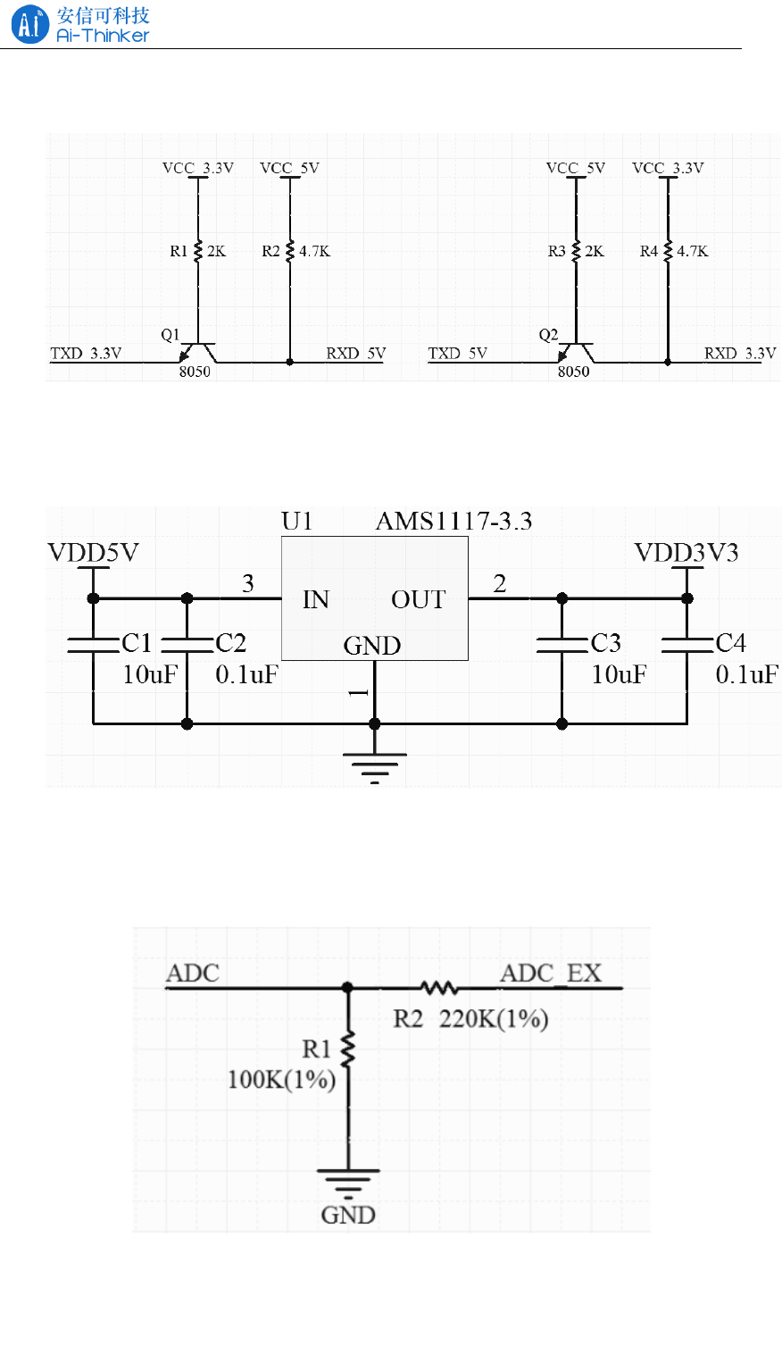
4.4 GPIO Level Conversion
Figure 4.8 Transistor level conversion
4.5 Power Supply Reference Design
Figure 4.9 Power supply reference
4.6 ADC Supply Reference Design
Figure 4.10 ADC supply reference
ESP-01/07/12 Series Modules User's Manual V1.4
Copyright © 2017 Shenzhen Ai-Thinker Technology Co., Ltd All Rights Reserved
Page 16 of
23
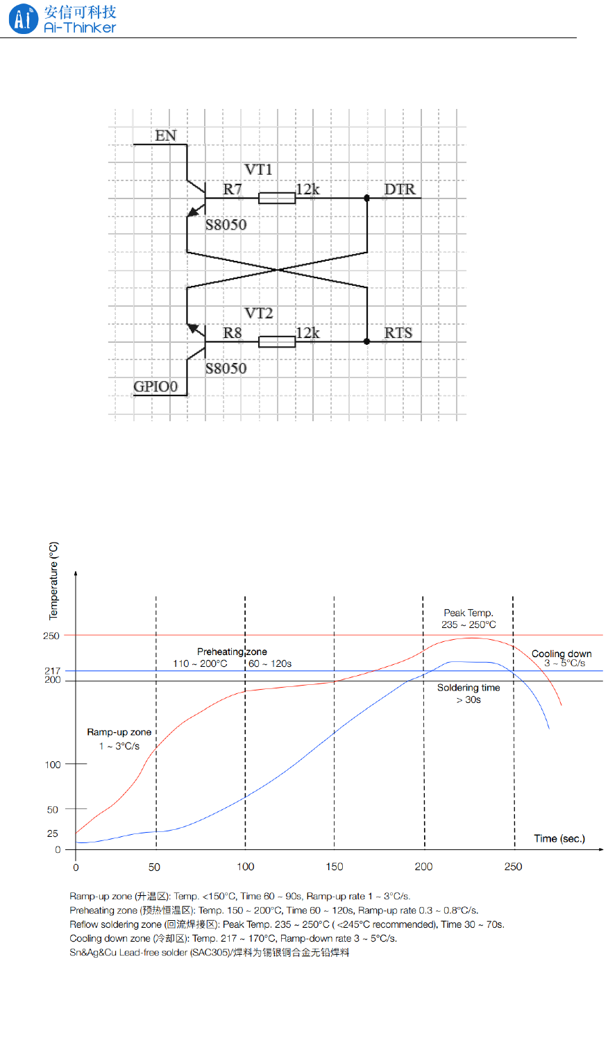
4.7 Automatically Download Reference Design
Figure 4.11 Automatically Download Reference Design
4.8 Reflow oven temperature curve
Figure 4.12 Reflow furnace temperature curve

ESP-01/07/12 Series Modules User's Manual V1.4
Copyright © 2017 Shenzhen Ai-Thinker Technology Co., Ltd All Rights Reserved
Page 17 of
23
5 Usage Guide
ESP8266 series module factory default built-in AT firmware, and the default
baud rate of 115200, can refer to 4.1 typical application diagram to build the
minimum system circuit, then the AT command operation.
Serial and network debugging tools download: http://wiki.ai-thinker.com/tools
5.1 Introduction To The Basic AT Command
This chapter only describes the common AT commands, please refer to
http://wiki.aithinker.com/esp8266/docs#at。
5.1.1 AT
parameters
No
Description
Test AT is OK
Example
AT
OK
5.1.2 AT+GMR
parameters
No
Description
Returns the firmware version information
Example
AT+GMR
AT version:1.2.0.0(Jul 1 2016 20:04:45)
SDK version:1.5.4.1(39cb9a32)
Ai-Thinker Technology Co. Ltd.
Dec 2 2016 14:21:16
OK
5.1.3 AT+RST
parameters
No
Description
soft restart module
Example
AT+RST
OK

ESP-01/07/12 Series Modules User's Manual V1.4
Copyright © 2017 Shenzhen Ai-Thinker Technology Co., Ltd All Rights Reserved
Page 18 of
23
5.1.4 AT+RESTORE
parameters
No
Description
Reset the module to factory settings
Example
AT+RESTORE
OK
5.2 Use Examples
This section explains how to configure two modules through the serial port on
the PC side to communicate with each other over TCP/UDP. For more examples,
please refer to: http://wiki.ai-thinker.com/esp8266/examples/at_demo. Test, through
the PC side instead of one end of the module to establish the appropriate connection.
5.2.1 TCP Communication Test
TCP Server is in AP mode and TCP Client is Station mode.
TCP Server Configuration:
Ai-Thinker Technology Co. Ltd.
ready
AT+CWMODE=2 //configured for AP mode
OK
AT+CWSAP_DEF="TCP_Server","12345678",5,4 //Configure AP
information
OK
AT+CIFSR //Query the local IP address
+CIFSR:APIP,"192.168.4.1"
+CIFSR:APMAC,"a2:20:a6:19:c7:0a"
OK
AT+CIPMUX=1 //open multiple links

ESP-01/07/12 Series Modules User's Manual V1.4
Copyright © 2017 Shenzhen Ai-Thinker Technology Co., Ltd All Rights Reserved
Page 19 of
23
OK
AT+CIPSERVER=1 //open the server
OK
0,CONNECT //There is a client connected to the server
+IPD,0,10:Ai-Thinker //received 10 data (Ai-Thinker)
AT+CIPSERVER=0 //Close the server
OK
0,CLOSED //TCP connection is off
TCP Client Configuration:
Ai-Thinker Technology Co. Ltd.
ready
AT+CWMODE=1 //configured for station mode
OK
AT+CWJAP_DEF="TCP_Server","12345678" //Connect to AP
WIFI CONNECTED
WIFI GOT IP
OK
AT+CIFSR //Query the local IP address
+CIFSR:STAIP,"192.168.4.2"
+CIFSR:STAMAC,"5c:cf:7f:91:8b:3b"
OK
AT+CIPMUX=0 //open single link
OK
AT+CIPSTART="TCP","192.168.4.1",333 //Connect to TCP server
CONNECT
OK
AT+CIPSEND=10 //send 10 bytes of data to the server side

ESP-01/07/12 Series Modules User's Manual V1.4
Copyright © 2017 Shenzhen Ai-Thinker Technology Co., Ltd All Rights Reserved
Page 20 of
23
OK
> //After the emergence of the symbol serial port to send
Ai-Thinker (without carriage return line)
Recv 10 bytes //The serial port receives the data
SEND OK //sent successfully
CLOSED //TCP connection is closed
5.2.2 UDP Communication Test
One is in AP mode , the local port is 8001, and the other is Station mode. the
local port is 8002.
AP Configuration:
Ai-Thinker Technology Co. Ltd.
ready
AT+CWMODE=2 //configured for AP mode
OK
AT+CWSAP_DEF="TCP_Server","12345678",5,4 //AP information
OK
AT+CIFSR //Query the local IP address
+CIFSR:APIP,"192.168.4.1"
+CIFSR:APMAC,"a2:20:a6:19:c7:0a"
OK
AT+CIPSTART="UDP","192.168.4.2",8002,8001,0 //Open UDP
connection
CONNECT
OK
+IPD,10:Ai-Thinker //received 10 data (Ai-Thinker)
AT+CIPSEND=10 //send 10 bytes of data to the server
OK

ESP-01/07/12 Series Modules User's Manual V1.4
Copyright © 2017 Shenzhen Ai-Thinker Technology Co., Ltd All Rights Reserved
Page 21 of
23
> //After the emergence of the symbol serial port to send
Ai-Thinker (without carriage return line)
Recv 10 bytes //The serial port receives the data
SEND OK
AT+CIPCLOSE //close the UDP connection
CLOSED
OK
Station Configuration:
Ai-Thinker Technology Co. Ltd.
ready
AT+CWMODE=2 //configured for station mode
OK
AT+CWSAP_DEF="TCP_Server","12345678",5,4 //Connect to AP
OK
AT+CIFSR //Query the local IP address
+CIFSR:STAIP,"192.168.4.2"
+CIFSR:STAMAC,"5c:cf:7f:91:8b:3b"
OK
AT+CIPSTART="UDP","192.168.4.1",8001,8002,0 //Open UDP connection
CONNECT
OK
AT+CIPSEND=10 //send 10 bytes of data to the server
OK
> //After the emergence of the symbol serial port to send
Ai-Thinker (without carriage return line)
Recv 10 bytes //The serial port receives the data
SEND OK

ESP-01/07/12 Series Modules User's Manual V1.4
Copyright © 2017 Shenzhen Ai-Thinker Technology Co., Ltd All Rights Reserved
Page 22 of
23
+IPD,10:Ai-Thinker //received 10 data (Ai-Thinker)
AT+CIPCLOSE //close the UDP connection
CLOSED
OK
6 FAQ
6.1 Garbage Instructions When Power Is On
ESP8266 chip itself supports 26MHz and 40MHz crystal, if the use of 40MHz
crystal, the default baud rate of 115200, if the use of 26MHz crystal, the UART0
power after the baud rate = 26 * 115200/40 = 74880, the letter can be ESP8266
Series modules are used 26MHz, because the general serial port tool does not support
the baud rate, so there will be printed on the garbled.
You can use the security serial interface assistant to configure the baud rate
74880 to view the startup information.
Note: part of the USB to TTL does not support 74880 baud rate, the computer
comes with RS232 to TTL does not support 74880 baud rate, recommend the use of
FT232, CP2102, CH340 and other chips.
6.2 How To Shield The Power When The Garbled
U0TXD default power will be system printing, through the UART's internal pin
switching function, user_init () call system_uart_swap () function, the new U0TXD
change to GPIO15, U0RXD change to GPIO13, the hardware connection on the two
cited Feet can be serial communication.
Note: After the exchange, the download pin on the hardware is still the original
U0TXD and U0RXD.
6.3 Can’t Burn Normally
Refer to http://wiki.ai-thinker.com/esp_download to download, pay attention to
download before the module to ensure that the download mode.
ESP-01/07/12 Series Modules User's Manual V1.4
Copyright © 2017 Shenzhen Ai-Thinker Technology Co., Ltd All Rights Reserved
Page 23 of
23
6.4 SDK Development Environment
Refer to http://wiki.ai-thinker.com/ai_ide_install to build the SDK development
environment.
6.5 Startup Information Description
Start, if the power and serial port connection is normal, then the baud rate 74880
to see the first sentence is as follows:
ets Jan 8 2013,rst cause:1, boot mode:(3,6)
The start and start modes of the module can be analyzed based on the print
information:
rst cause :
1: Power restart
2: External reset
4: Hardware watchdog reset
boot mode:
The second in parentheses has no practical meaning, the first can refer to the
following table to start the information analysis:
Table 6.1 Startup Mode Description
Value
Mode
GPIO0
GPIO2
GPIO15
0
-
0
0
0
1
Download Mode
0
1
0
2
-
1
0
0
3
Run mode
1
1
0
4
-
0
0
1
5
-
0
1
1
6
-
1
0
1
7
-
1
1
1
7 Module Selection
model
ESP-01
ESP-01S
ESP-01M
ESP-07
ESP-07S
ESP-12F
ESP-12S
Package
DIP-8
DIP-8
SMD-18
SMD-16
SMD-16
SMD-22
SMD-16

ESP-01/07/12 Series Modules User's Manual V1.4
Copyright © 2017 Shenzhen Ai-Thinker Technology Co., Ltd All Rights Reserved
Page 24 of
23
Size(mm)
24.7*14.4
24.7*14.4
18*18
21.2*16.0
17.0*16.0
24.0*16.0
24.0*16.0
layer
2
2
4
2
4
4
4
Flash size
8Mbit
8Mbit
8Mbit
8Mbit
32Mbit
32Mbit
32Mbit
Certificati
on
-
-
-
-
FCC/CE
FCC/CE
FCC/CE
Antenna
PCB
PCB
PCB
Ceramic
IPEX
IPEX
PCB
PCB
Indicator
light
TXD0
POWER
GPIO2
GPIO2
POWER
-
GPIO2
GPIO2
GPIO2
Available
IO
2
2
11
9
9
9
9
For more selection information please see http://wiki.ai-thinker.com/esp8266 or
contact us.

ESP-01/07/12 Series Modules User's Manual V1.4
Copyright © 2017 Shenzhen Ai-Thinker Technology Co., Ltd All Rights Reserved
Page 25 of
23
8 Contact US
Official website: https://www.ai-thinker.com
Develop Wiki: http://wiki.ai-thinker.com
Official forum: http://bbs.ai-thinker.com
Sample purchase: https://anxinke.taobao.com
Business cooperation: sales@aithinker.com
Technical support: support@aithinker.com
Telephone: 0755-29162996
Company Address: 6/F, Block C2, Huafeng Industrial Park, Hangcheng Road,
Bao'an Road, Baoan District, Shenzhen ,China
WeChat AiSmart APP