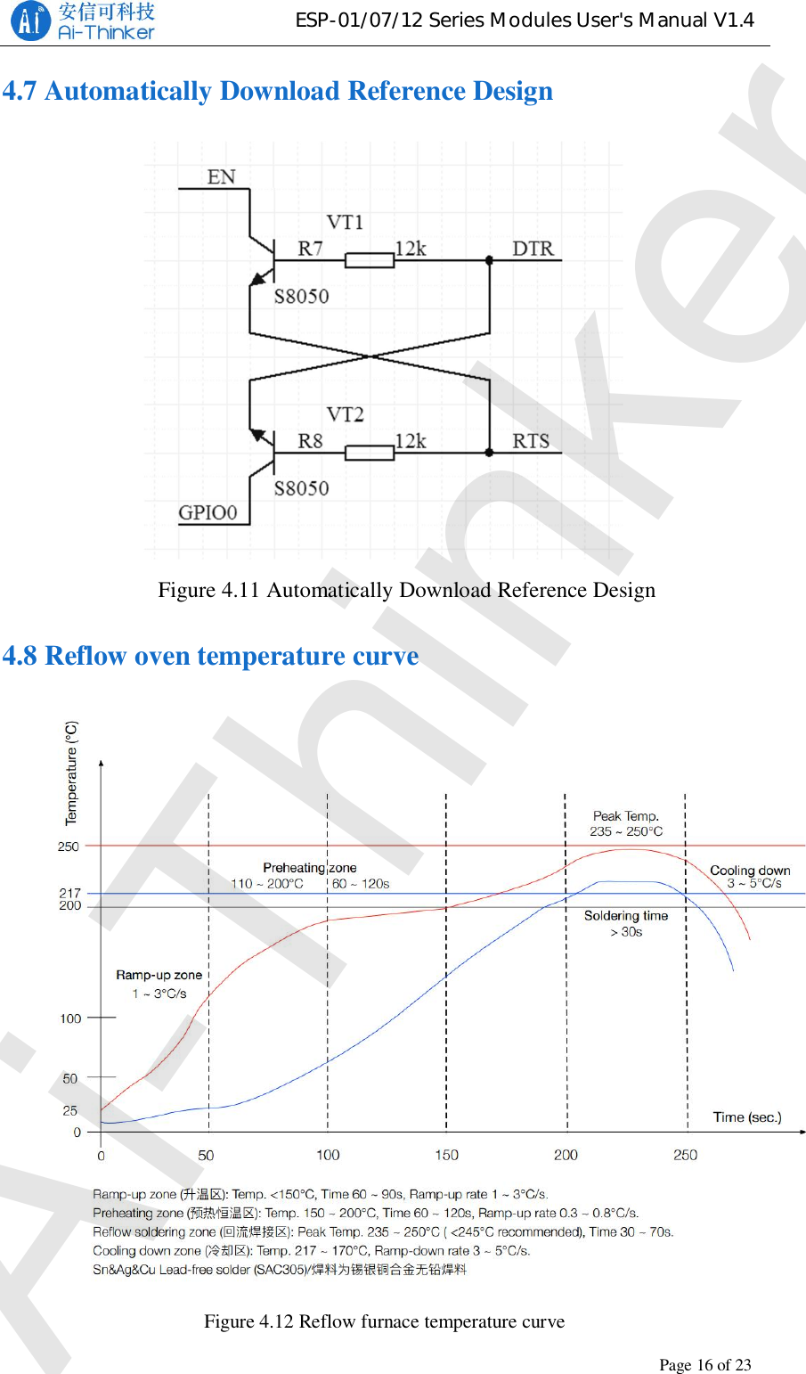
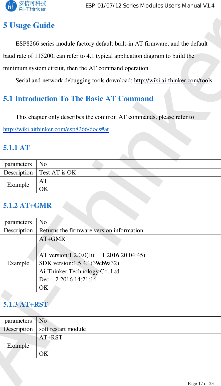
Ai Thinker Technology ESP01F WiFi module User Manual

Shenzhen Ai-Thinker Technology co., LTD WiFi module

User Manual

ESP-01/07/12 Series Modules User's ManualVersion 1.4Ai-Thinker IncCopyright(c)2017Ai-Thinker
ESP-01/07/12 Series Modules User's Manual V1.4Revision RecordDate Version Author Release Notes2017.07.01 V1.0  Wang Chong First Version2017.09.04 V1.1  Wang Chong Add ESP-01M, Delete ESP-12E2017.12.18 V1.2  Fang Dongbin Modify the GPIO4 pin description, changethe contact number2018.3.10 V1.3 Lv Junxiong Add ESP-01F2018.8.16 V1.4 Lv Junxiong Add ESP-01EAi-Thinker
ESP-01/07/12 Series Modules User's Manual V1.4FCC STATEMENTChanges or modifications not expressly approved by the party responsible for compliancecould void the user’s authority to operate the equipment.This device complies with Part 15 of the FCC Rules. Operation is subject to the followingtwo conditions:(1) this device may not cause harmful interference, and(2) this device must accept any interference received, including interference that may causeundesired operation.Note: This equipment has been tested and found to comply with the limits for a Class Bdigital device, pursuant to Part 15 of the FCC Rules. These limits are designed to providereasonable protection against harmful interference in a residential installation. This equipmentgenerates, uses, and can radiate radio frequency energy, and if not installed and used inaccordance with the instructions, may cause harmful interference to radio communications.However, there is no guarantee that interference will not occur in a particular installation. Ifthis equipment does cause harmful interference to radio or television reception, which can bedetermined by turning the equipment off and on, the user is encouraged to try to correct theinterference by one or more of the following measures:– Reorient or relocate the receiving antenna.– Increase the separation between the equipment and receiver.– Connect the equipment into an outlet on a circuit different from that to which the receiveris connected.– Consult the dealer or an experienced radio/TV technician for help.Please notice that if the FCC identification number is not visible when the module isinstalled inside another device, then the outside of the device into which the module is installedmust also display a label referring to the enclosed module. This exterior label can use wordingsuch as the following: “Contains FCC ID:2AHMR-ESP01M” or “Contains FCCID:2AHMR-ESP07S”or “Contains FCC ID:2AHMR-ESP12S” or “Contains FCCID:2AHMR-ESP12F” or “Contains FCC ID:2AHMR-ESP01E”or “Contains FCCID:2AHMR-ESP01F”any similar wording that expresses the same meaning may be used.This equipment complies with FCC radiation exposure limits set forth for an uncontrolledenvironment. This equipment should be installed and operated with a minimum distance of 20cmbetween the radiator & your body. This transmitter must not be co-located or operating inconjunction with any other antenna or transmitter.The module is limited to OEM installation ONLY.The OEM integrator is responsible for ensuring that the end-user has no manual instruction to remove or install module.The module is limited to installation in mobile application.A separate approval is required for all other operating configurations, including portable configurations with respect to Part 2.1093 and difference antenna configurations.There is requirement that the grantee provide guidance to the host manufacturer for compliance with Part 15B requirements.Ai-Thinker
ESP-01/07/12 Series Modules User's Manual V1.4Table Of Contents1 Product Overview ...........................................................................................11.1 Product Features ...................................................................................11.2 Application Plan ...................................................................................12 Module Interface.............................................................................................22.1 Package Size ........................................................................................22.1 Pin Definition .......................................................................................62.2 Boot Mode ...........................................................................................73 Electrical Characteristics.................................................................................83.1 Maximum Ratings ................................................................................83.2 Suggested Working Environment .........................................................83.3 Digital Port Features ............................................................................83.4 Power Consumption .............................................................................83.5 Transmit  Power .................................................................................. 103.6 Receive Sensitivity ............................................................................. 104 Hardware Guidance ...................................................................................... 114.1 Typical Applications .......................................................................... 114.2 PCB Antenna Display Instructions ..................................................... 134.3 Module Peripheral Routing Instructions ............................................. 144.4 GPIO Level Conversion ..................................................................... 154.5 Power Supply Reference Design ........................................................ 154.6 ADC Supply Reference Design .......................................................... 154.7 Automatically Download Reference Design ....................................... 164.8 Reflow oven temperature curve .......................................................... 165 Usage Guide ................................................................................................. 175.1 Introduction To The Basic AT Command ........................................... 175.1.1 AT ........................................................................................... 175.1.2 AT+GMR ................................................................................ 175.1.3  AT+RST .................................................................................. 17Ai-Thinker
ESP-01/07/12 Series Modules User's Manual V1.45.1.4 AT+RESTORE........................................................................ 185.2 Use Examples .................................................................................... 185.2.1 TCP Communication Test ........................................................ 185.2.2 UDP Communication Test ....................................................... 206 FAQ ............................................................................................................. 226.1 Garbage Instructions When Power Is On ............................................ 226.2 How To Shield The Power When The Garbled ................................... 226.3 Can’t Burn Normally ....................................................................... 226.4 SDK Development Environment ........................................................ 236.5 Startup Information Description ......................................................... 237 Module Selection .......................................................................................... 238 Contact US ................................................................................................... 25Ai-Thinker
ESP-01/07/12 Series Modules User's Manual V1.4Copyright © 2017 Shenzhen Ai-Thinker Technology Co., Ltd All Rights ReservedPage1of231 Product OverviewESP8266 series wireless module is a series of cost-effective Wi-Fi SOC modulewhich can be developed independently. The series modules support the standardIEEE802.11 b/g/n protocol, built-in complete TCP/IP protocol stack. Users can usethis series of modules to add networking capabilities to existing devices, or to buildstandalone network controllers.Ai-Thinker Technology can provide customers with a complete hardware,software reference program, in order to shorten your product development cycle, foryour cost savings.1.1 Product FeaturesThe smallest 802.11b/g/n Wi-Fi SOC moduleUsing low-power 32-bit CPU, can also serve as the applicationprocessorClocked at up to 160MHzBuilt-in 10 bit high precision ADCSupport UART/GPIO/IIC/PWM/ADC/HSPI and other interfacesIntegrated Wi-Fi MAC/BB/RF/PA/LNASupports multiple sleep modes, deep sleep current as low as 20uAEmbedded Lwip protocol stackSupport STA/AP/STA + AP work modeSupports Smart Config/AirKiss key distribution networkSerial port rate up to 4MbpsGeneral AT commands can be used quicklySupport SDK secondary developmentSupports serial local upgrade and remote firmware upgrade (FOTA)1.2 Application PlanIndustrial wireless controlInfant MonitorIP cameraSensor networkHousehold appliancesHome automationSmart socket/intelligent lightMesh networkWearable electronic productsWireless location sensing deviceSecurity ID tagWireless positioning system beaconAi-Thinker
ESP-01/07/12 Series Modules User's Manual V1.4Copyright © 2017 Shenzhen Ai-Thinker Technology Co., Ltd All Rights ReservedPage2of232 Module Interface2.1 Package SizeFigure 2.1 ESP-01/ESP-01S pin dimensions  Figure 2.2 ESP-01M pin dimensionsAi-Thinker
ESP-01/07/12 Series Modules User's Manual V1.4Copyright © 2017 Shenzhen Ai-Thinker Technology Co., Ltd All Rights ReservedPage3of23Figure 2.3 ESP-01F pin dimensionsFigure 2.4 ESP-07 pin dimensionsAi-Thinker
ESP-01/07/12 Series Modules User's Manual V1.4Copyright © 2017 Shenzhen Ai-Thinker Technology Co., Ltd All Rights ReservedPage4of23Figure 2.5 ESP-07S pin dimensionsFigure 2.6   ESP-12F pin dimensionsAi-Thinker
ESP-01/07/12 Series Modules User's Manual V1.4Copyright © 2017 Shenzhen Ai-Thinker Technology Co., Ltd All Rights ReservedPage5of23Figure 2.7 ESP-12S pin dimensionsFigure 2.7 ESP-01E pin dimensionsAi-Thinker
ESP-01/07/12 Series Modules User's Manual V1.4Copyright © 2017 Shenzhen Ai-Thinker Technology Co., Ltd All Rights ReservedPage6of23Table 2.1 ESP series module size tableModel Length(mm)Width(mm)Height(mmPAD size(mm)PinSpacing(mm)ShieldedShell(mm)Thickness(mm)ESP-01ESP-01S 24.7 14.4 11.0 1.5 x 1.5 2.54 - 1.0±0.1ESP-01M 18 18 2.8±0.2 - 1.6 2.0 0.8±0.1ESP-01F 11 10 2.0±0.2 1.1 1.2 0.8±0.1ESP-07 21.2 16.0 3.0±0.2 - 2.0 2.0 0.8±0.1ESP-07S 17.0 16.0 3.0±0.3 1 x 1.2 2.0 2.0 0.8±0.1ESP-12F 24.0 16.0 3.0±0.2 2.0 2.0 0.8±0.1ESP-12S 24.0 16.0 3.0±0.2 1 x 1.2 2.0 2.0 0.8±0.12.1 Pin DefinitionTable 2.2 ESP Series Module Pin Function DefinitionsPin Number PinNameRemarks0101S 01M 01E 01F0707S12S12F7 18 18 16 1 1 RST Reset Pin, Active Low-16 16 32 2 ADC AD conversiont, Input voltagerange 0~1V, the value rangeis6 9 9 43 3 EN  Chip Enabled Pin, Active High-17 17 54 4 IO16 Connect with RST pin to wakeup Deep Sleep-15 15 65 5 IO14 HSPI_CLKIR_TI2C_SCLI2SI_WS- 14 14 76 6 IO12 HSPI_MISO- 5 5 87 7 IO13 HSPI_MOSI; UART0_CTS8 2 2 17 8 8 VCC Module power supply pin, thevoltage range of 3.0 ~ 3.6V- - - --9CS0 Flash chip select signal- - - --10 MISOSlave Output Master Input- 11 11 --11 IO9 Gpio9Only ESP-01M/01E CanAi-Thinker
ESP-01/07/12 Series Modules User's Manual V1.4Copyright © 2017 Shenzhen Ai-Thinker Technology Co., Ltd All Rights ReservedPage7of23-12 12 --12 IO10 Gpio10,Only ESP-01M/01E Can- - - --13 MOSIMaster Output Slave Input- - - --14 SCLKClock1 1 1 2/18 915 GND GND- 6 6 910 16 IO15 HSPI_CSU0_RTSI2SO_BCK2 7 7 10 11 17 IO2 U1_TXDI2C_SDAI2SO_WS3 8 8 11 12 18 IO0 GPIO0HSPI_MISOI2SI_DATA-10 10 12 13 19 IO4 GPIO4-13 13 13 14 20 IO5 IR_R4 4 4 14 15 21 RXD GPIO3I2SO_DATA5 3 3 15 16 22 TXD GPIO1- - 1 1- -  ANTOnly ESP-01F/01E CanNote: Only GPIO4 and GPIO5 are low at boot time, the other GPIO are high.2.2 Boot ModeTable 2.3 Description of the ESP series module boot modeMode CH_PD(EN) RST GPIO15 GPIO0 GPIO2 TXD0Downloadmode high high low low high highRunningmode high high low high high highChip Testmode high high - - - lowAi-Thinker
ESP-01/07/12 Series Modules User's Manual V1.4Copyright © 2017 Shenzhen Ai-Thinker Technology Co., Ltd All Rights ReservedPage8of233 Electrical Characteristics3.1 Maximum RatingsTable 3.1 Maximum RatingsRated value condition Value UnitStorage Temperature --40 ~ 90 Maximum WeldingTemperature-250 Supply Voltage IPC/JEDECJ-STD-020+3.0 ~ +3.6 V3.2 Suggested Working EnvironmentTable 3.2 Recommended working environmentWork Environment Name Min Typ Max UnitOperating Temperature -20 20 85 Supply Voltage VDD 3.0 3.3 3.6 V3.3 Digital Port FeaturesTable 3.3 Digital Port FeaturesPort Name Min Typ Max UnitInput logic level low VIL -0.3 - 0.25 * VDD VInput logic level high VIH  0.75 * VDD - VDD + 0.3 VOutput logic level low VOL N-0.1 * VDD VOutput logic levelhigh VOH 0.8 * VDD -N VNote: Unless otherwise specified, the test conditions are: VDD = 3.3 V andtemperature 20 .3.4 Power ConsumptionAll measurements are made at the antenna interface without SAW filters.Ai-Thinker
ESP-01/07/12 Series Modules User's Manual V1.4Copyright © 2017 Shenzhen Ai-Thinker Technology Co., Ltd All Rights ReservedPage9of23All transmit data is based on a 90% duty cycle measured in the continuous firingmode.Table 3.4 Power consumptionMode Min TypMaxUnitTransmit 802.11b, CCK 11Mbps, POUT = +17dBm170 mATransmit 802.11g, OFDM 54Mbps, POUT = +15dBm140 mATransmit 802.11n, MCS7, POUT = + 13dBm 120 mAReceive 802.11b, packet length 1024 bytes,-80dBm50 mAReceive 802.11g, packet length 1024 bytes,-70dBm56 mAReceive 802.11n, packet length 1024 bytes,-65dBm56 mAModem-Sleep20 mALight-Sleep2mADeep-Sleep20 uAPower Off 1 uANote: Modem-Sleep is used to require the CPU to remain in operation, such as PWM or I2S.When there is no data transmission while maintaining a WiFi connection, power off the WiFiModem circuit according to the 802.11 standard (eg U-APSD). For example, in DTIM3, everysleep 300mS, wake up 3mS receive AP Beacon package, etc., the overall average current of about20mA.Note : Light-Sleep for CPU can be suspended applications, such as WiFi switch. If thereis no data transmission while maintaining a WiFi connection, the WiFi Modem circuit can beswitched off and the CPU is powered down according to the 802.11 standard (eg U-APSD). Forexample, at DTIM3, every sleep 300 ms, wake up 3 ms to receive AP's Beacon packets, etc., theoverall average current is about 2 mA.Note: Deep-Sleep is used for applications that do not have to keep the WiFi connection for along time, such as a sensor that measures the temperature once every 100 seconds. Every 300 swake up after 0.3s - 1s connected to the AP to send data, the overall average current can be muchsmaller than 2mA.Ai-Thinker
ESP-01/07/12 Series Modules User's Manual V1.4Copyright © 2017 Shenzhen Ai-Thinker Technology Co., Ltd All Rights ReservedPage10of233.5 Transmit PowerTable 3.5 RF parametersDescribe Min Typ Max Unit802.11b@11Mbps 14 16 18 dBm802.11g@54Mbps 12 14 16 dBm802.11n@HT20, MCS7 11 13 15 dBm3.6 Receive SensitivityTable 3.6 Receiving SensitivityParameter Min Typ Max UnitDSSS, 1 Mbps -95 dBmCCK, 11 Mbps -80 dBm6 Mbps (1/2 BPSK) -88 dBm54 Mbps (3/4 64-QAM) -70 dBmHT20, MCS7 (65 Mbps, 72.2 Mbps) -67 dBmAi-Thinker
ESP-01/07/12 Series Modules User's Manual V1.4Copyright © 2017 Shenzhen Ai-Thinker Technology Co., Ltd All Rights ReservedPage11of234 Hardware Guidance4.1 Typical ApplicationsNote: You can’t use USB to TTL 3.3V or 5V power supply, it is recommendedto use two dry batteries or after conversion through the LDO 3.3V, it is stronglyrecommended to buy a new development board.Figure 4.1 Typical application of ESP-01Figure 4.2 Typical application of ESP-01SFigure 4.3 Typical application of ESP-01MAi-Thinker
ESP-01/07/12 Series Modules User's Manual V1.4Copyright © 2017 Shenzhen Ai-Thinker Technology Co., Ltd All Rights ReservedPage12of23Figure 4.4 Typical application of ESP-01FFigure 4.5 Typical application of ESP-07Figure 4.6 Typical application of ESP-07SAi-Thinker
ESP-01/07/12 Series Modules User's Manual V1.4Copyright © 2017 Shenzhen Ai-Thinker Technology Co., Ltd All Rights ReservedPage13of23Figure 4.7 Typical application of ESP-12E/ESP-12FFigure 4.8 Typical application of ESP-12SFigure 4.9 Typical application of ESP-01E4.2 PCB Antenna Display InstructionsThe ESP8266 series module can be soldered to the PCB board. In order to getthe best RF performance of the end product, please pay attention to the rationalAi-Thinker
ESP-01/07/12 Series Modules User's Manual V1.4Copyright © 2017 Shenzhen Ai-Thinker Technology Co., Ltd All Rights ReservedPage14of23design of the module and the placement of the antenna on the bottom plate accordingto this guide.Option 1 (recommended):Place the module along the edge of the PCB board, and the antenna is placedoutside the frame or along the board and the bottom is hollowed out;Option 2:The module placed along the PCB board side, the antenna placed along theboard and the bottom of the hollow;Option 3:Place the module along the board side of the board, the antenna placed along theboard and the bottom are not copper.Figure 4.7 ESP-12S antenna placement instructions4.3 Module Peripheral Routing InstructionsThe ESP8266 series modules integrates high-speed GPIO and peripheralinterfaces, which can cause severe switching noise. If some applications require highpower and EMI characteristics, it is recommended to connect 10 to 100 ohms inseries on digital I/O lines. This can suppress overshoot when switching powersupplies and make the signal smooth. Series resistance can also prevent electrostaticdischarge (ESD) to some extent.Ai-Thinker
ESP-01/07/12 Series Modules User's Manual V1.4Copyright © 2017 Shenzhen Ai-Thinker Technology Co., Ltd All Rights ReservedPage15of234.4 GPIO Level ConversionFigure 4.8 Transistor level conversion4.5 Power Supply Reference DesignFigure 4.9 Power supply reference4.6 ADC Supply Reference DesignFigure 4.10 ADC supply referenceAi-Thinker
ESP-01/07/12 Series Modules User's Manual V1.4Copyright © 2017 Shenzhen Ai-Thinker Technology Co., Ltd All Rights ReservedPage16of234.7 Automatically Download Reference DesignFigure 4.11 Automatically Download Reference Design4.8 Reflow oven temperature curveFigure 4.12 Reflow furnace temperature curveAi-Thinker
ESP-01/07/12 Series Modules User's Manual V1.4Copyright © 2017 Shenzhen Ai-Thinker Technology Co., Ltd All Rights ReservedPage17of235 Usage GuideESP8266 series module factory default built-in AT firmware, and the defaultbaud rate of 115200, can refer to 4.1 typical application diagram to build theminimum system circuit, then the AT command operation.Serial and network debugging tools download: http://wiki.ai-thinker.com/tools5.1 Introduction To The Basic AT CommandThis chapter only describes the common AT commands, please refer tohttp://wiki.aithinker.com/esp8266/docs#at5.1.1 ATparameters NoDescription Test AT is OKExample ATOK5.1.2 AT+GMRparameters NoDescription Returns the firmware version informationExampleAT+GMRAT version:1.2.0.0(Jul   1 2016 20:04:45)SDK version:1.5.4.1(39cb9a32)Ai-Thinker Technology Co. Ltd.Dec   2 2016 14:21:16OK5.1.3 AT+RSTparameters NoDescription soft restart moduleExampleAT+RSTOKAi-Thinker
ESP-01/07/12 Series Modules User's Manual V1.4Copyright © 2017 Shenzhen Ai-Thinker Technology Co., Ltd All Rights ReservedPage18of235.1.4 AT+RESTOREparameters NoDescription Reset the module to factory settingsExampleAT+RESTOREOK5.2 Use ExamplesThis section explains how to configure two modules through the serial port onthe PC side to communicate with each other over TCP/UDP. For more examples,please refer to: http://wiki.ai-thinker.com/esp8266/examples/at_demo. Test, throughthe PC side instead of one end of the module to establish the appropriate connection.5.2.1 TCP Communication TestTCP Server is in AP mode and TCP Client is Station mode.TCP Server ConfigurationAi-Thinker Technology Co. Ltd.readyAT+CWMODE=2 //configured for AP modeOKAT+CWSAP_DEF="TCP_Server","12345678",5,4 //Configure APinformationOKAT+CIFSR //Query the local IP address+CIFSR:APIP,"192.168.4.1"+CIFSR:APMAC,"a2:20:a6:19:c7:0a"OKAT+CIPMUX=1 //open multiple linksAi-Thinker
ESP-01/07/12 Series Modules User's Manual V1.4Copyright © 2017 Shenzhen Ai-Thinker Technology Co., Ltd All Rights ReservedPage19of23OKAT+CIPSERVER=1  //open the serverOK0,CONNECT //There is a client connected to the server+IPD,0,10:Ai-Thinker //received 10 data (Ai-Thinker)AT+CIPSERVER=0  //Close the serverOK0,CLOSED //TCP connection is offTCP Client ConfigurationAi-Thinker Technology Co. Ltd.readyAT+CWMODE=1 //configured for station modeOKAT+CWJAP_DEF="TCP_Server","12345678" //Connect to APWIFI CONNECTEDWIFI GOT IPOKAT+CIFSR //Query the local IP address+CIFSR:STAIP,"192.168.4.2"+CIFSR:STAMAC,"5c:cf:7f:91:8b:3b"OKAT+CIPMUX=0 //open single linkOKAT+CIPSTART="TCP","192.168.4.1",333 //Connect to TCP serverCONNECTOKAT+CIPSEND=10 //send 10 bytes of data to the server sideAi-Thinker
ESP-01/07/12 Series Modules User's Manual V1.4Copyright © 2017 Shenzhen Ai-Thinker Technology Co., Ltd All Rights ReservedPage20of23OK>//After the emergence of the symbol serial port to sendAi-Thinker (without carriage return line)Recv 10 bytes //The serial port receives the dataSEND OK //sent successfullyCLOSED //TCP connection is closed5.2.2 UDP Communication TestOne is in AP mode , the local port is 8001, and the other is Station mode. thelocal port is 8002.AP ConfigurationAi-Thinker Technology Co. Ltd.readyAT+CWMODE=2 //configured for AP modeOKAT+CWSAP_DEF="TCP_Server","12345678",5,4 //AP informationOKAT+CIFSR //Query the local IP address+CIFSR:APIP,"192.168.4.1"+CIFSR:APMAC,"a2:20:a6:19:c7:0a"OKAT+CIPSTART="UDP","192.168.4.2",8002,8001,0 //Open UDPconnectionCONNECTOK+IPD,10:Ai-Thinker //received 10 data (Ai-Thinker)AT+CIPSEND=10 //send 10 bytes of data to the serverOKAi-Thinker
ESP-01/07/12 Series Modules User's Manual V1.4Copyright © 2017 Shenzhen Ai-Thinker Technology Co., Ltd All Rights ReservedPage21of23>//After the emergence of the symbol serial port to sendAi-Thinker (without carriage return line)Recv 10 bytes //The serial port receives the dataSEND OKAT+CIPCLOSE //close the UDP connectionCLOSEDOKStation ConfigurationAi-Thinker Technology Co. Ltd.readyAT+CWMODE=2 //configured for station modeOKAT+CWSAP_DEF="TCP_Server","12345678",5,4 //Connect to APOKAT+CIFSR //Query the local IP address+CIFSR:STAIP,"192.168.4.2"+CIFSR:STAMAC,"5c:cf:7f:91:8b:3b"OKAT+CIPSTART="UDP","192.168.4.1",8001,8002,0 //Open UDP connectionCONNECTOKAT+CIPSEND=10 //send 10 bytes of data to the serverOK>//After the emergence of the symbol serial port to sendAi-Thinker (without carriage return line)Recv 10 bytes //The serial port receives the dataSEND OKAi-Thinker
ESP-01/07/12 Series Modules User's Manual V1.4Copyright © 2017 Shenzhen Ai-Thinker Technology Co., Ltd All Rights ReservedPage22of23+IPD,10:Ai-Thinker //received 10 data (Ai-Thinker)AT+CIPCLOSE //close the UDP connectionCLOSEDOK6 FAQ6.1 Garbage Instructions When Power Is OnESP8266 chip itself supports 26MHz and 40MHz crystal, if the use of 40MHzcrystal, the default baud rate of 115200, if the use of 26MHz crystal, the UART0power after the baud rate = 26 * 115200/40 = 74880, the letter can be ESP8266Series modules are used 26MHz, because the general serial port tool does not supportthe baud rate, so there will be printed on the garbled.You can use the security serial interface assistant to configure the baud rate74880 to view the startup information.Note: part of the USB to TTL does not support 74880 baud rate, the computercomes with RS232 to TTL does not support 74880 baud rate, recommend the use ofFT232, CP2102, CH340 and other chips.6.2 How To Shield The Power When The GarbledU0TXD default power will be system printing, through the UART's internal pinswitching function, user_init () call system_uart_swap () function, the new U0TXDchange to GPIO15, U0RXD change to GPIO13, the hardware connection on the twocited Feet can be serial communication.Note: After the exchange, the download pin on the hardware is still the originalU0TXD and U0RXD.6.3 Can’t Burn NormallyRefer to http://wiki.ai-thinker.com/esp_download to download, pay attention todownload before the module to ensure that the download mode.Ai-Thinker
ESP-01/07/12 Series Modules User's Manual V1.4Copyright © 2017 Shenzhen Ai-Thinker Technology Co., Ltd All Rights ReservedPage23of236.4 SDK Development EnvironmentRefer to http://wiki.ai-thinker.com/ai_ide_install to build the SDK developmentenvironment.6.5 Startup Information DescriptionStart, if the power and serial port connection is normal, then the baud rate 74880to see the first sentence is as follows:ets Jan   8 2013,rst cause:1, boot mode:(3,6)The start and start modes of the module can be analyzed based on the printinformation:rst cause 1: Power restart2: External reset4: Hardware watchdog resetboot modeThe second in parentheses has no practical meaning, the first can refer to thefollowing table to start the information analysis:Table 6.1 Startup Mode DescriptionValue Mode GPIO0 GPIO2 GPIO150 - 0 0 01Download Mode 0 1 02 - 1 0 03Run mode 1 1 04 - 0 0 15 - 0 1 16 - 1 0 17 - 1 1 17 Module Selectionmodel ESP-01 ESP-01S ESP-01M ESP-07 ESP-07S ESP-12F ESP-12SPackage DIP-8  DIP-8 SMD-18 SMD-16 SMD-16 SMD-22 SMD-16Ai-Thinker
ESP-01/07/12 Series Modules User's Manual V1.4Copyright © 2017 Shenzhen Ai-Thinker Technology Co., Ltd All Rights ReservedPage24of23Size(mm) 24.7*14.4 24.7*14.4 18*18 21.2*16.0 17.0*16.0 24.0*16.0 24.0*16.0layer 2 2 4 2 4 4 4Flash size 8Mbit  8Mbit  8Mbit  8Mbit 32Mbit 32Mbit 32MbitCertification ----FCC/CE FCC/CE FCC/CEAntenna PCB PCB PCB CeramicIPEX IPEX PCB PCBIndicatorlightTXD0POWER GPIO2 GPIO2POWER -GPIO2 GPIO2 GPIO2AvailableIO 2 2 11 9 9 9 9For more selection information please see http://wiki.ai-thinker.com/esp8266 orcontact us.Ai-Thinker
ESP-01/07/12 Series Modules User's Manual V1.4Copyright © 2017 Shenzhen Ai-Thinker Technology Co., Ltd All Rights ReservedPage25of238 Contact USOfficial website: https://www.ai-thinker.comDevelop Wiki: http://wiki.ai-thinker.comOfficial forum: http://bbs.ai-thinker.comSample purchase: https://anxinke.taobao.comBusiness cooperation: sales@aithinker.comTechnical support: support@aithinker.comTelephone: 0755-29162996Company Address: 6/F, Block C2, Huafeng Industrial Park, Hangcheng Road,Bao'an Road, Baoan District, Shenzhen ,ChinaWeChat   AiSmart APPAi-Thinker

Navigation menu