Ai Thinker Technology ESP12F ESP-12F User Manual ESP 12F
Shenzhen Ai-Thinker Technology co., LTD ESP-12F ESP 12F
UserManual.wiki
>
Ai Thinker Technology
>
ESP12F User Manual
User Manual
Navigation menu
Upload a User Manual
Namespaces
Wiki Guide
HTML
PDF
Info
Views
User Manual
Discussion / Help
Navigation
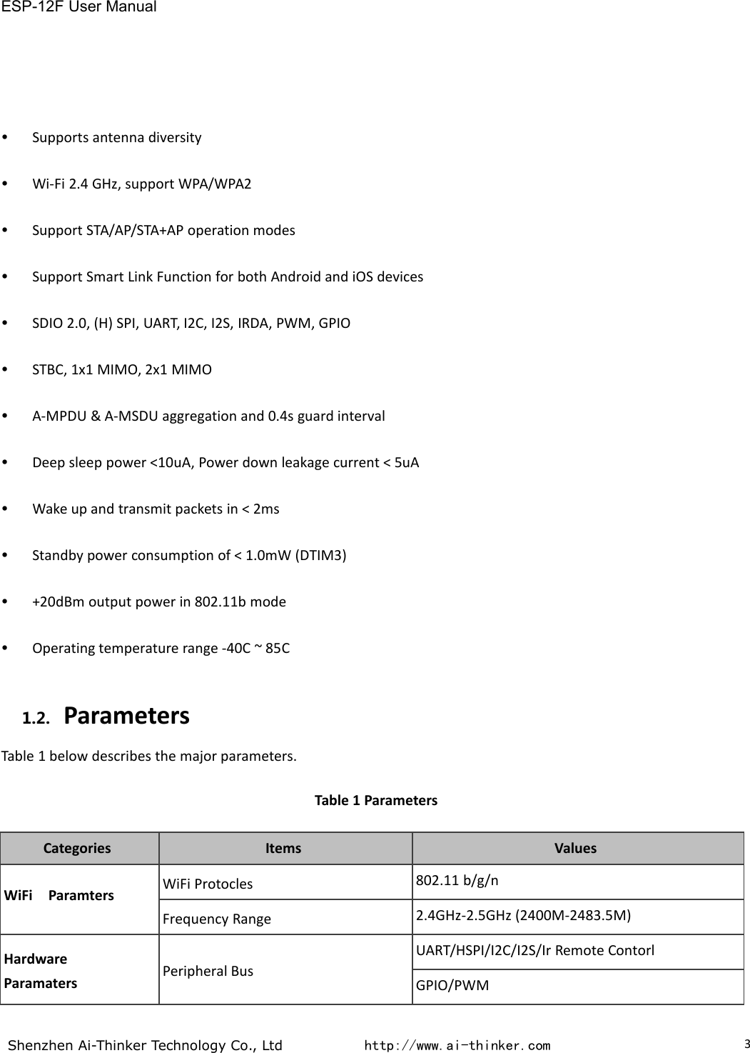
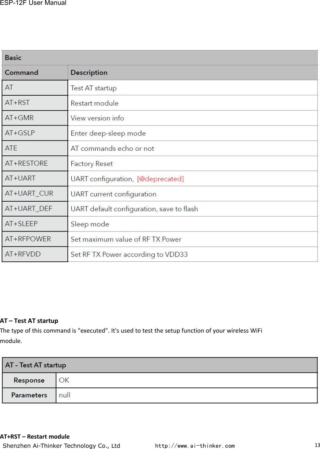
![ESP-12F User ManualShenzhen Ai-Thinker Technology Co., Ltd http://www.ai-thinker.com12AT commands set is divided into: Basic AT commands, WiFi related AT commands, TCP / IP AT4.3.1.AT Command DescriptionTable 8 Each Command set contains four types of AT commands.Notes:1. Not all AT Command has four commands.2. [] = default value, not required or may not appear3. String values require double quotation marks, for example:AT+CWSAP="ESP756290","21030826",1,44. Baudrate = 1152005. AT Commands has to be capitalized, and end with "/r/n"4.3.2.Basic AT Command SetThe ESP8266 wireless WiFi modules can be driven via the serial interface using the standard ATcommands. Here is a list of some basic AT commands that can be used.Table9 basic AT commands](https://usermanual.wiki/Ai-Thinker-Technology/ESP12F/User-Guide-3564272-Page-14.png)