Ai Thinker Technology ESP12S WIFI MODULE User Manual ESP 12S revised
Shenzhen Ai-Thinker Technology co., LTD WIFI MODULE ESP 12S revised
Contents
- 1. ESP-12S User Manual-revised
- 2. User Manual
ESP-12S User Manual-revised
ESP-12S User Manual
REV:1.0
2016.7

ESP-12S User Manual
Shenzhen Ai-Thinker Technology Co., Ltd http://www.ai-thinker.com
FCC STATEMENT
This device complies with Part 15 of the FCC Rules. Operation is subject to the following two conditions:
(1) This device may not cause harmful interference.
(2) This device must accept any interference received, including interference that may cause undesired operation.
Any changes or modifications not expressly approved by the party responsible for compliance could void the user’s
authority to operate the equipment.
Please notice that if the FCC identification number is not visible when the module is installed inside another device,
then the outside of the device into which the module is installed must also display a label referring to the enclosed
module. This exterior label can use wording such as the following: “Contains FCC ID: 2AHMR-ESP12S” any similar
wording that expresses the same meaning may be used.
This equipment complies with FCC radiation exposure limits set forth for an uncontrolled environment.This equipment
should be installed and operated with a minimum distance of 20cmbetween the radiator & your body. This transmitter
must not be co-located or operating inconjunction with any other antenna or transmitter.
CE Mark Warning
The module is limited to OEM installation ONLY.
The OEM integrator is responsible for ensuring that the end-user has no manual instruction to remove or install
module.
The module is limited to installation in mobile application;
A separate approval is required for all other operating configurations, including portable configurations with respect to
Part 2.1093 and difference antenna configurations.
There is requirement that the grantee provide guidance to the host manufacturer for compliance with Part 15B
requirements.
ESP-12S User Manual
Shenzhen Ai-Thinker Technology Co., Ltd http://www.ai-thinker.com
1
Table Of Contents
1. Preambles ............................................................................................................................................................... 2
1.1. Features ............................................................................................................................................... 3
1.2. Parameters ........................................................................................................................................... 4
2. Pin Descriptions ...................................................................................................................................................... 5
2.1. Interfaces ............................................................................................................................................. 6
2.2. Pin Mode .............................................................................................................................................. 8
2.3. Antenna interface ................................................................................................................................ 8
3. Package information and OEM installation method ............................................................................................. 9
3.1. Package information .......................................................................................................................... 10
3.2. OEM installation mathod ................................................................................................................... 10
4. Absolute Maximum Ratings ................................................................................................................................ 11
4.1Recommended Operating Conditions ......................................................................................................... 11
4.2.AT commend Testing ................................................................................................................................... 11
4.3.AT commend ............................................................................................................................................... 12
4.3.1.AT Command Description ........................................................................................................................ 12
4.3.2.Basic AT Command Set ............................................................................................................................ 12
ESP-12S User Manual
Shenzhen Ai-Thinker Technology Co., Ltd http://www.ai-thinker.com
2
1. Preambles
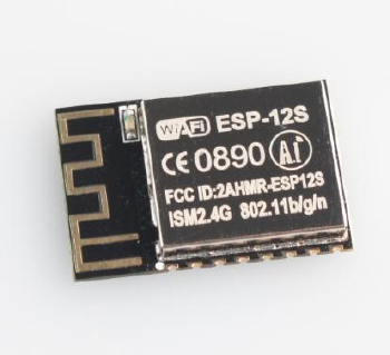
ESP-12S WiFi module is developed by AI-Thinker Co.,Ltd, core processor ESP8266 in smaller sizes of the module
encapsulates Tensilica L106 integrates industry-leading ultra low power 32-bit MCU micro, with the 16-bit short mode,
clock speed support 80 MHz, 160 MHz, supports the RTOS, integrated Wi-Fi MAC/BB/RF/PA/LNA, on-board antennas.
The module supports standard IEEE802.11 b/g/n agreement, complete TCP/IP protocol stack. Users can use the
add modules to an existing device networking, or building a separate network controller.
ESP8266 is high integration wireless SOCs, designed for space and power constrained mobile platform designers.
It provides unsurpassed ability to embed Wi-Fi capabilities within other systems, or to function as a standalone
application, with the lowest cost, and minimal space requirement.
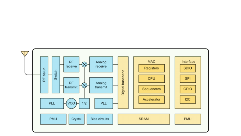
Figure 1 ESP8266EX Functional Block Diagram
ESP8266EX offers a complete and self-contained Wi-Fi networking solution; it can be used to host the application
or to offload Wi-Fi networking functions from another application processor.
When ESP8266EX hosts the application, it boots up directly from an external flash. In has integrated cache to
improve the performance of the system in such applications.
Alternately, serving as a Wi-Fi adapter, wireless internet access can be added to any micro controllerbased design
with simple connectivity (SPI/SDIO or I2C/UART interface).
ESP8266EX is among the most integrated WiFi chip in the industry; it integrates the antenna switches, RF balun,
power amplifier, low noise receive amplifier, filters, power management modules, it requires minimal external circuitry,
and the entire solution, including front-end module, is designed to occupy minimal PCB area.
ESP8266EX also integrates an enhanced version of Tensilica’s L106 Diamond series 32-bit processor, with on-chip
SRAM, besides the Wi-Fi functionalities. ESP8266EX is often integrated with external sensors and other application
specific devices through its GPIOs; codes for such applications are provided in examples in the SDK.
ESP-12S User Manual
Shenzhen Ai-Thinker Technology Co., Ltd http://www.ai-thinker.com
3
1.1. Features
• 802.11 b/g/n
• Integrated low power 32-bit MCU
• Integrated 10-bit ADC
• Integrated TCP/IP protocol stack
• Integrated TR switch, balun, LNA, power amplifier and matching network
• Integrated PLL, regulators, and power management units
• Supports antenna diversity
• Wi-Fi 2.4 GHz, support WPA/WPA2
• Support STA/AP/STA+AP operation modes
• Support Smart Link Function for both Android and iOS devices
• SDIO 2.0, (H) SPI, UART, I2C, I2S, IRDA, PWM, GPIO
• STBC, 1x1 MIMO, 2x1 MIMO
• A-MPDU & A-MSDU aggregation and 0.4s guard interval
• Deep sleep power <10uA, Power down leakage current < 5uA
• Wake up and transmit packets in < 2ms
• Standby power consumption of < 1.0mW (DTIM3)
• +20dBm output power in 802.11b mode
• Operating temperature range -40C ~ 85C

ESP-12S User Manual
Shenzhen Ai-Thinker Technology Co., Ltd http://www.ai-thinker.com
4
1.2. Parameters
Table 1 below describes the major parameters.
Table 1 Parameters
Categories
Items
Values
WiFi Paramters
WiFi Protocles
802.11 b/g/n
Frequency Range
2.4GHz-2.5GHz (2400M-2483.5M)
Hardware
Paramaters
Peripheral Bus
UART/HSPI/I2C/I2S/Ir Remote Contorl
GPIO/PWM
Operating Voltage
3.3V
Operating Current
Average value: 80mA
Operating Temperature Range
-40°~125°
Ambient Temperature Range
Normal temperature
Package Size
18mm*20mm*3mm
External Interface
N/A
Software
Parameters
Wi-Fi mode
station/softAP/SoftAP+station
Security
WPA/WPA2
Encryption
WEP/TKIP/AES
Firmware Upgrade
UART Download / OTA (via network) /
download and write firmware via host
Ssoftware Development
Supports Cloud Server Development / SDK
for custom firmware development
Network Protocols
IPv4, TCP/UDP/HTTP/FTP
User Configuration
AT Instruction Set, Cloud Server, Android/iOS APP
ESP-12S User Manual
Shenzhen Ai-Thinker Technology Co., Ltd http://www.ai-thinker.com
5
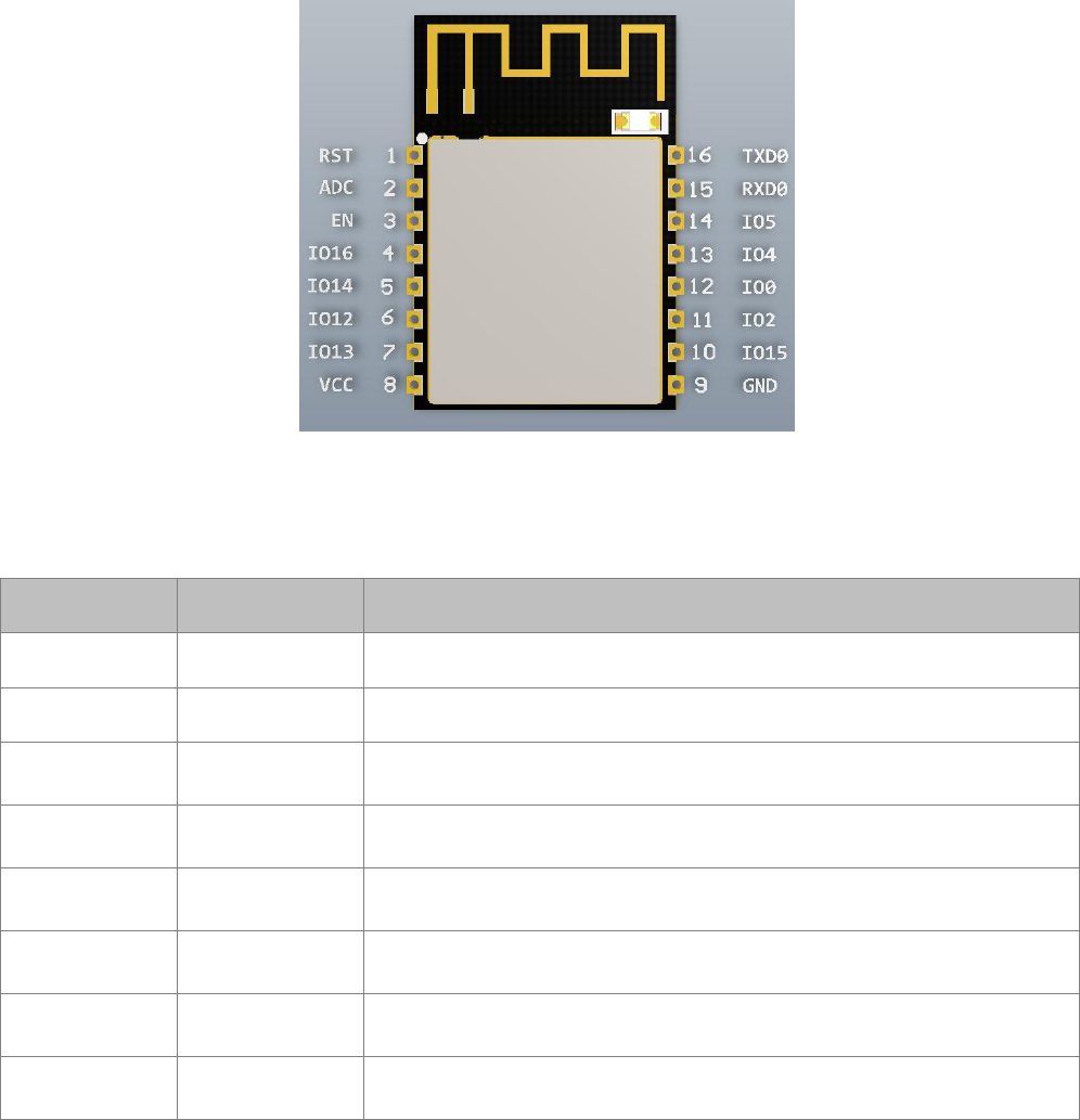
2. Pin Descriptions
There are altogether 16 pin counts, the definitions of which are described in Table 2 below.
Figure 2 ESP-12S pinout
Table 2 ESP-12S pin description
Pin number
Pin name
function
1
RST
Reset module
2
ADC
A/d conversion result. Input voltage range 0~1V, value range: 0~1024
3
EN
Chip enable pin. Active high
4
GPIO16
GPIO16; can be used to wake up the chipset from deep sleep mode
5
GPIO14
GPIO14; HSPI_CLK
6
GPIO12
GPIO12; HSPI_MISO
7
GPIO13
GPIO13; HSPI_MOSI; UART0_CTS
8
VCC
3.3V power supply (VDD)

ESP-12S User Manual
Shenzhen Ai-Thinker Technology Co., Ltd http://www.ai-thinker.com
6
9
GND
GND
10
GPIO15
GPIO15; MTDO; HSPICS; UART0_RTS
11
GPIO2
GPIO2; UART1_TXD
12
GPIO0
GPIO0
13
GPIO4
GPIO4
14
GPIO5
GPIO5
15
RXD0
UART0_RXD; GPIO3
16
TXD0
UART0_TXD; GPIO1
2.1. Interfaces
Table 3 Descriptions of Interfaces
Interface
Pin Name
Description
HSPI
IO12(MISO),
IO13(MOSI)
IO14(CLK),
IO15(CS)
SPI Flash , display screen, and MCU can be connected using HSPI
interface
PWM
IO12(R),
IO15(G),
IO13(B)
Currently the PWM interface has four channels, but users can extend
the channels according to their own needs. PWM interface can be
used to control LED lights, buzzers, relays, electronic machines, and
so on.
IR Remote
Control
IO14(IR_T),
IO5(IR_R)
The functionality of Infrared remote control interface can be
implemented via software programming. NEC coding, modulation,
and demodulation are used by this interface. The frequency of
modulated carrier signal is 38KHz.
ADC
TOUT
ESP8266EX integrates a 10-bit analog ADC. It can be used to test the
power supply voltage of VDD3P3 (Pin3 and Pin4) and the input
power voltage of TOUT (Pin 6). However, these two functions cannot
be used simultaneously. This interface is typically used in sensor

ESP-12S User Manual
Shenzhen Ai-Thinker Technology Co., Ltd http://www.ai-thinker.com
7
products.
I2C
IO14(SCL),
IO2(SDA)
I2C interface can be used to connect external sensor products and
display screens, etc.
UART
UART0:
TXD(U0TXD),
RXD(U0RXD),
IO15(RTS),
IO13(CTS)
UART1:
IO2(TXD)
Devices with UART interfaces can be connected with the module.
Downloading: U0TXD+U0RXD or GPIO2+U0RXD
Communicating: UART0: U0TXD, U0RXD, MTDO (U0RTS), MTCK
(U0CTS)
Debugging: UART1_TXD (GPIO2) can be used to print debugging
information.
By default, UART0 will output some printed information when the
device is powered on and is booting up. If this issue exerts influence
on some specific applications, users can exchange the inner pins of
UART when initializing, that is to say, exchange U0TXD, U0RXD with
U0RTS, U0CTS.
I2S
I2S Input:
IO12 (I2SI_DATA) ;
IO13 (I2SI_BCK );
IO14 (I2SI_WS);
I2S interface is mainly used for collecting, processing, and
transmission of audio data.
I2S Output::
IO15 (I2SO_BCK );
IO3 (I2SO_DATA);
IO2 (I2SO_WS ).

ESP-12S User Manual
Shenzhen Ai-Thinker Technology Co., Ltd http://www.ai-thinker.com
8
2.2. Pin Mode
Table 4 Pin Mode
Mode
GPIO15
GPIO0
GPIO2
UART
low
low
high
Flash Boot
low
high
high
2.3. Antenna interface
ESP-12S Modules through the IPEX interface to connect to external antenna.
The antenna must be in line with the 802.11g/802.11b IEEE standard, and the antenna parameters are shown in
the following table:
Table 5 Antenna parameters
Rating
Value
Frequency range
2.4~2.4825GHz
Impedance
50Ω
ESP-12S User Manual
Shenzhen Ai-Thinker Technology Co., Ltd http://www.ai-thinker.com
9
3. Package information and OEM installation method
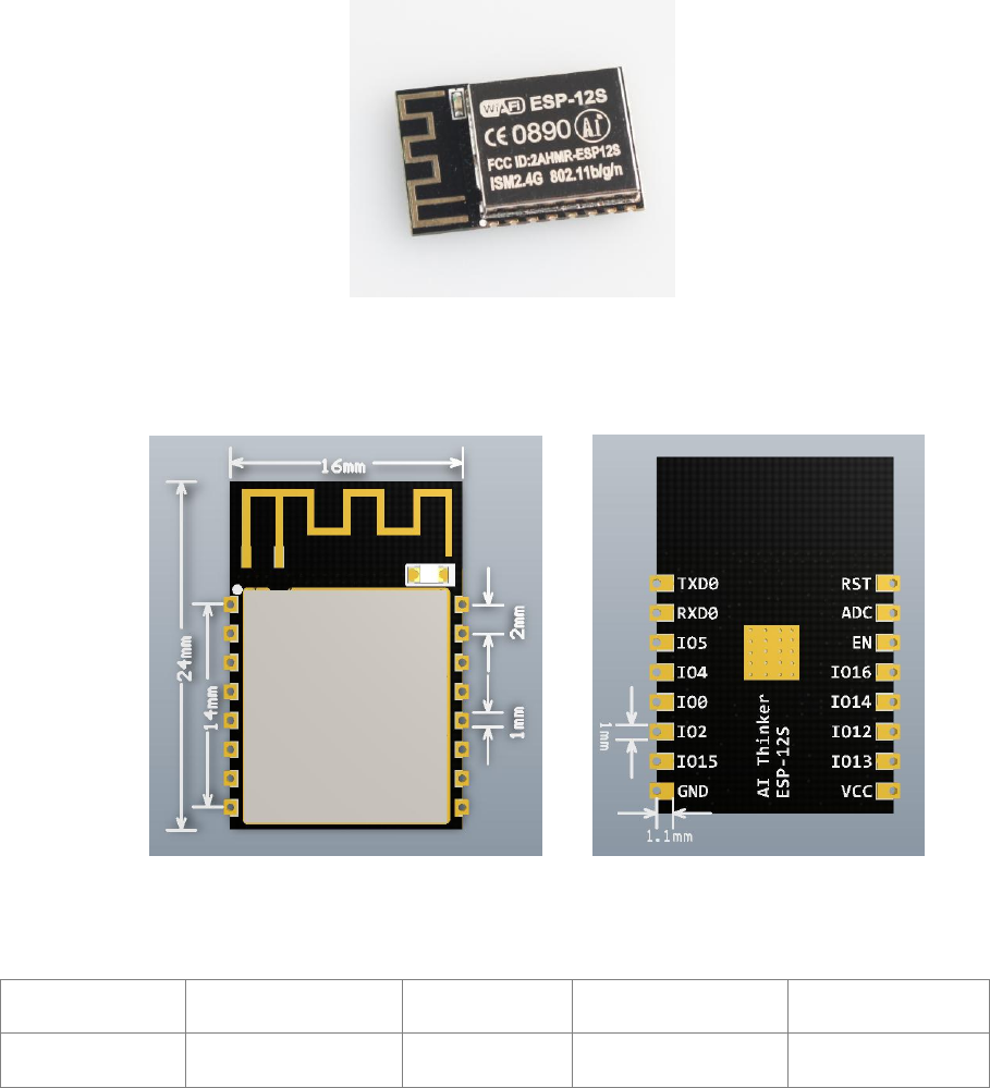
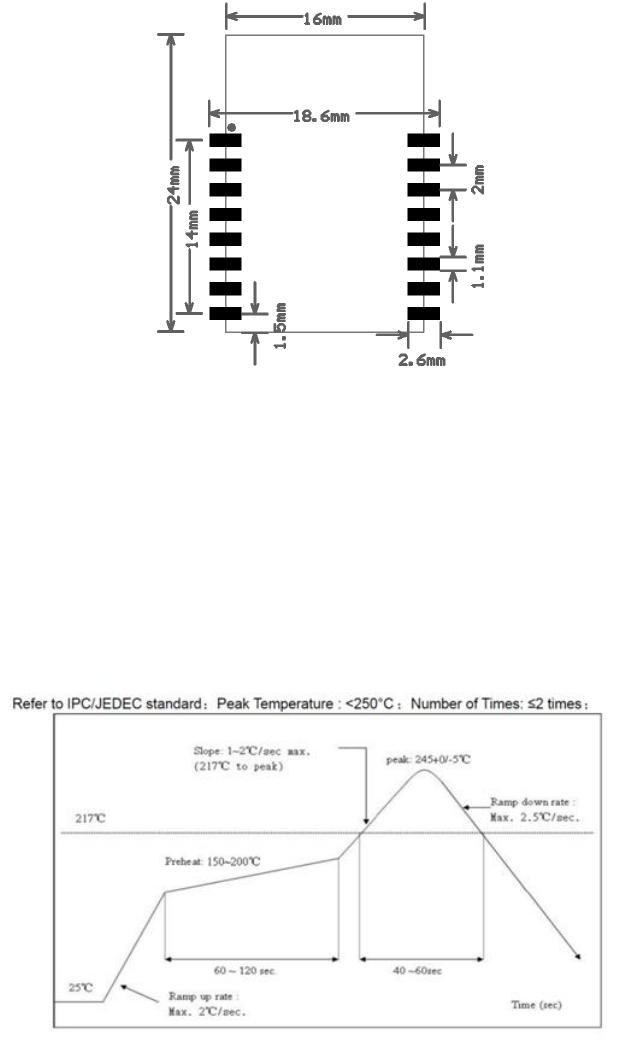
The external size of theESP-12S WiFi module is 16mm*17mm*3mm, as is illustrated in Figure 4 below:
Figure 3 Top View of ESP-07s WiFi Module
Figure 4 Dimensions of ESP-12S WiFi Module
Table 5 Dimensions of ESP-12S WiFi Module
Length
width
Height
PAD Size(Bottom)
Pin Pitch
16mm
17mm
3 mm
1 mm x 1.2 mm
2mm
ESP-12S User Manual
Shenzhen Ai-Thinker Technology Co., Ltd http://www.ai-thinker.com
10
3.1. Package information
ESP-12S use a half hole patch package, Module PCB Footprint shown in the following figure:
Figure 5 Module PCB Footprint
3.2. OEM installation mathod
Using ESP-12S module Please reference in front of the package information in the Layout on the main board for
OEM factory .Please pay more attention Module's direction and the antenna close to the edge of board is better ,the
Components and layout should not be on the bottom of antenna then soldering the module.when the module be
soldering can not in the environment of high temperature ,We recommend the reflow soldering temperature curves is
shown in figure 6:
Figure 6 Recommend reflow soldering temperature curves
ESP-12S User Manual
Shenzhen Ai-Thinker Technology Co., Ltd http://www.ai-thinker.com
11
4. Absolute Maximum Ratings
Table 6 Absolute Maximum Ratings
Rating
Condition
Value
Unit
Storage Temperature
-40 to 125
℃
Maximum Soldering Temperature
260
℃
Supply Voltage
IPC/JEDEC J-STD-020
+3.0 to +3.6
V
4.1Recommended Operating Conditions
Table 7 Recommended Operating Conditions
Operating Condition
Symbol
Min
Typ
Max
Unit
Operating Temperature
-40
20
125
℃
Supply voltage
VDD
3.0
3.3
3.6
V
4.2.AT commend Testing
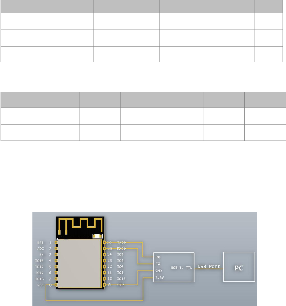
1.Hardware connection
As shown in Figure 7, ESP-12S via a USB to TTL Tool connected to the computer, software tool through the serial
port on the computer can be AT instruction test
Figure 7 ESP-12S connect with computer
ESP-12S User Manual
Shenzhen Ai-Thinker Technology Co., Ltd http://www.ai-thinker.com
12
4.3.AT commend
Espressif AT instruction set functions and methods of use
AT commands set is divided into: Basic AT commands, WiFi related AT commands, TCP / IP AT
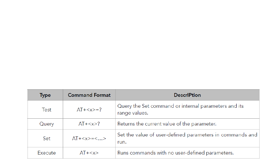
4.3.1.AT Command Description
Table 8 Each Command set contains four types of AT commands.
Notes:
1. Not all AT Command has four commands.
2. [] = default value, not required or may not appear
3. String values require double quotation marks, for example:
AT+CWSAP="ESP756290","21030826",1,4
4. Baudrate = 115200
5. AT Commands has to be capitalized, and end with "/r/n"
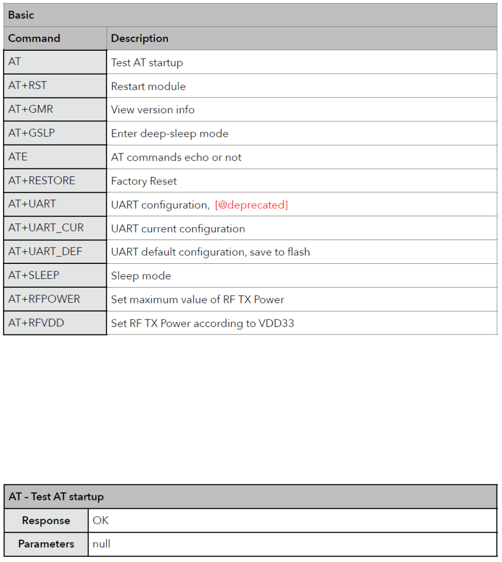
4.3.2.Basic AT Command Set
The ESP8266 wireless WiFi modules can be driven via the serial interface using the standard AT
commands. Here is a list of some basic AT commands that can be used.
ESP-12S User Manual
Shenzhen Ai-Thinker Technology Co., Ltd http://www.ai-thinker.com
13
Table9 basic AT commands
AT – Test AT startup
The type of this command is "executed". It's used to test the setup function of your wireless WiFi
module.
ESP-12S User Manual
Shenzhen Ai-Thinker Technology Co., Ltd http://www.ai-thinker.com
14
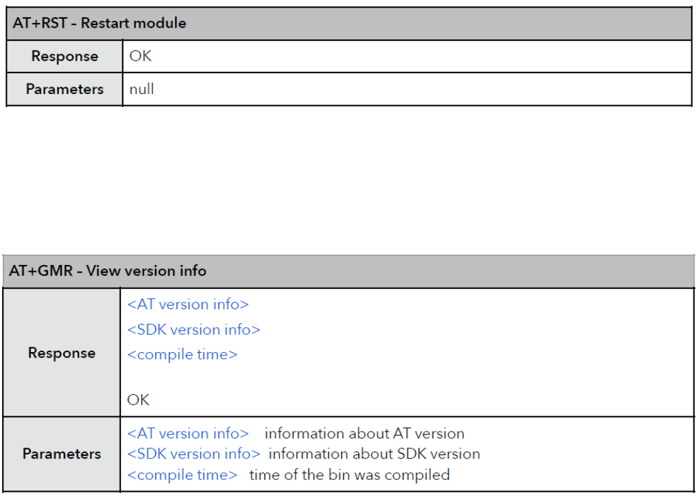
AT+RST – Restart module
The type of this command is "executed". It’s used to restart the module.
AT+GMR – View version info
This AT command is used to check the version of AT commands and SDK that you are using, the type
of which is "executed".
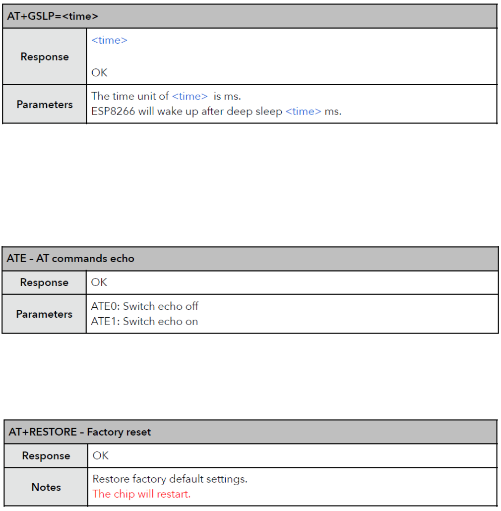
AT+GSLP – Enter deep-sleep mode
This command is used to invoke the deep-sleep mode of the module, the type of which is "set". A
minor adjustment has to be made before the module enter this deep sleep mode, i.e., connect
XPD_DCDC with EXT_RSTB via 0R.
ESP-12S User Manual
Shenzhen Ai-Thinker Technology Co., Ltd http://www.ai-thinker.com
15
ATE – AT commands echo
This command ATE is an AT trigger command echo. It means that entered commands can be echoed
back to the sender when ATE command is used. Two parameters are possible. The command returns
"OK" in normal cases and "ERROR" when a parameter other than 0 or 1 was specified.
AT+RESTORE – Factory reset
This command is used to reset all parameters saved in flash (according to appendix), restore the
factory default settings of the module. The chip will be restarted when this command is executed.
Detailed instruction test, please refer to the Esp8266 AT Instruction Set, can be downloaded to shun official website。