AiRISTA Flow T301-W1 WiFi Location Tag Transmitter User Manual W4 User Guide 08012014x
Ekahau Inc. WiFi Location Tag Transmitter W4 User Guide 08012014x
Contents
- 1. manual
- 2. User Guide
User Guide

4
User
W

Ekahau, the Ekahau logo, Ekahau Site Survey, Ekahau Mobile Survey, Ekahau Location Survey,
Ekahau HeatMapper, Ekahau Engine, Ekahau RTLS Controller, Ekahau Positioning Engine,
Ekahau RTLS Controller, Ekahau Manager, Ekahau Activator, Ekahau Finder, Ekahau Vision,
Ekahau Tracker, Ekahau Logger, Ekahau T201, Ekahau T301, Ekahau NIC-54, Ekahau NIC-300,
Ekahau Client, and Ekahau Positioning Client are trademarks or registered trademarks of Ekahau.
Other product and company names may be trademarks or trade names of their respective owners.
The enclosed software contains implementations of Ekahau’s patent pending inventions.
This manual and the Ekahau software described in it are copyrighted, with all rights reserved. This
manual and the Ekahau software described in it may not be copied, except as otherwise provided
in your software license.
The contents of this document are provided “as is.” Except as may be required by applicable law,
no warranties of any kind, either express or implied, including, but not limited to, the implied war-
ranties of merchantability and fitness for a particular purpose, are made in relation to the accuracy,
reliability or contents of this document. Ekahau reserves the right to revise this document or withdraw
it at any time without prior notice.
Export of this technology may be controlled by the United States Government. Diversion contrary
to U.S. law prohibited.
Your use of the Ekahau software described in this user manual and its documentation are governed
by the terms set forth in your license agreement. Your use of this Ekahau software contrary to the
terms of this User Manual may void the warranty, if any, described in your license agreement.
Under no circumstances shall Ekahau be responsible for any loss of data or income, or any special,
incidental, punitive, consequential or indirect damages howsoever caused.
You may not use any Ekahau software or hardware products in hazardous environments (such
as operation of nuclear facilities, aircraft navigation or control, environments containing high levels
of dust, or mines) or in Life-Critical Solutions, unless you have advised Ekahau that they will be
used in a hazardous environment or in a Life-Critical Solution and Ekahau has had an opportunity
to evaluate further whether, and on what terms and conditions, the software or hardware products
may be licensed for your intended use. The term “Life-Critical Solution” means an application
software package or hardware device whose functioning or malfunctioning may result directly or
indirectly in physical injury or loss of human life.
Ekahau tags must always be used in compliance with the user environment and instructions con-
tained in the User Manual for the tags.
Copyright © Ekahau, Inc. 2000-2013. All rights reserved.

iii
W4
Table of
Contents
1 Introduction ....................................................................................................................... 1
1.1 Software Release Level ........................................................................................... 1
1.2 Features of W4 ........................................................................................................ 1
1.3 User Interface .......................................................................................................... 2
1.4 Attaching the Wristband ........................................................................................... 2
1.5 Status Indication LEDs ............................................................................................. 3
2 Initial Activation of the Tag .............................................................................................. 5
2.1 Installing Ekahau Activator 3 .................................................................................... 5
2.2 Supported Wi-Fi Adapters ........................................................................................ 5
2.3 Activation Procedure ................................................................................................ 5
2.3.1 Configuring Ekahau RTLS Controller Settings ............................................ 6
2.3.2 Configuring WLAN Settings ......................................................................... 7
2.3.3 Configuring Wi-Fi Channels in Use .............................................................. 8
2.3.4 Configuring IP Settings ................................................................................ 9
2.3.5 Activation ................................................................................................... 10
2.3.6 List of Available Settings in the Activator ................................................... 14
3 Configuration After Initial Activation ............................................................................ 17
3.1 Tag Configuration Settings in ERC Configs Page .................................................. 17
3.2 Tag Actions Available in ERC Tags Properties Page ............................................. 19
4 Tag Operation ................................................................................................................. 21
4.1 Button Activated Location Update .......................................................................... 21
4.2 Maintenance Call ................................................................................................... 21
4.3 De-activation / Resetting to Factory Settings ......................................................... 21
4.4 Firmware Update ................................................................................................... 21
4.5 Optimizing Battery Life ........................................................................................... 22
4.6 Turning off the W4 Tag ........................................................................................... 22
4.7 Charging the W4 tag .............................................................................................. 22
5 Technical specifications ................................................................................................ 27
5.1 General .................................................................................................................. 27
5.2 Wi-Fi ....................................................................................................................... 27
5.3 Operating Ranges from an Access Point ............................................................... 27
5.4 Care and Maintenance ........................................................................................... 27
6 Certifications .................................................................................................................. 29
7 Limited Warranty ............................................................................................................ 31
8 Disposing ………………………………………………………………………………………..31

iv
W4

1
Chapter 1. Introduction
1 Introduction
The Ekahau W4 Wi-Fi tag is part of Ekahau RTLS (Ekahau Real-Time Location System) that
consists of Ekahau tags, Ekahau RTLS Controller (ERC) software platform and Ekahau Vision
end-user application. It is designed to be worn by patients, employees, children and other individu-
als, and it enables real-time visibility into a person’s exact location – enterprise-wide, with reliable
room- and sub-room level accuracy.
1.1 Software Release Level
This User Guide documents the functionality available with software release level, 1.3.15.
1.2 Features of W4
The following features are included with this software release:
● Works with standard 802.11b/g/n Wi-Fi networks
○ 802.11g/n only in CCX or Ekahau blink mode
○ 802.11b needs to be enabled in the Wi-Fi network if association mode is used
● Support for 64/128-bit WEP key and WPA2-PSK authentication
● Static and dynamic IP addressing
● Configurable button for sending and acknowledging emergency or status messages
● Location reporting triggered by button, periodic timer, motion, and by Ekahau Location Beacons
● Support for Cisco CCX and Aruba beaconing mode
● Three-color status indication LED
● Vibration alarm for alerting the person wearing it
● Battery monitoring and reporting
● IR Location Beacon sensor for room, sub-room, and bay level accuracy
● Waterproof enclosure allowing it to be thoroughly sanitized after use
● Configuration using Ekahau Activator, standalone tag configuration software.
● Configuration using Ekahau RTLS Controller.
Chapter 1. Introduction 2
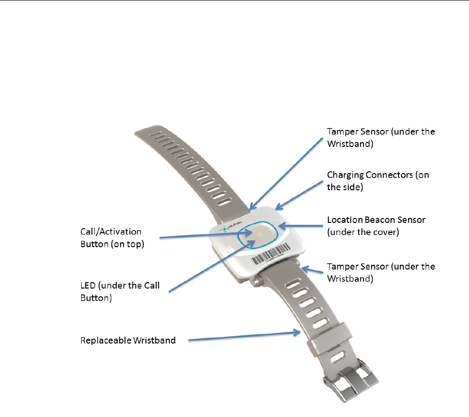
1.3 User Interface
Figure 1.1. W4 user interface
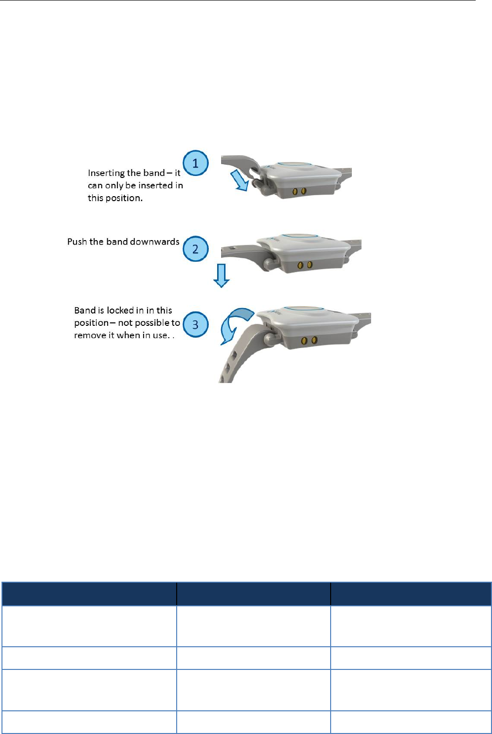
1.4 Attaching the Wristband
The wristband (two pieces) can be attached to the W4 tag as follows:
3 Chapter 1. Introduction
Figure 1.2. Inserting the wristband
1. Lift the end of the wristband to slide the beginning into the bar on the tag. The wristband will
not attach in any other position
2. Push the beginning part (tag side) of the wristband downwards
3. Lift the end of the wristband. The wristband is now locked onto its position.
For removal, push down the end of the wristband and lift the beginning part (tag side) up.
1.5 Status Indication LEDs
The tag is equipped with two multi-color LEDs that provide status indication. The table below lists
the different modes of the tag LEDs:
Action
LED
Status
Activation
3 x Green
12 x Red
Activation successful
Activation failed
De-activation (Reset)
3 x Green and Red
Reset successful
Charging
Orange
Green
Charging
Battery full
Button press
1 x Orange
Button press recognized

Chapter 1. Introduction 4
Action
LED
Status
Action ELP / EMP packet success
-
Success of the ELP / EMP packet
is not indicated with the LED
Alarm
Configurable
Can be configured to use any pat-
tern over EMP command

5 Chapter 2. Initial Activation of the Tag
2 Initial Activation of the Tag
When the tag is delivered it does not have any of the necessary configuration settings. These
environment specific settings need to be applied before the tag can connect to the network and
the ERC. The W4 tags are delivered with the battery charged to a storage charge, it is recommended
to fully charge the battery, before activating the tags first time. See charging instructions in chapter
Charging the W4 tag on page 22.
Tag activation is done using Ekahau Activator software that configures Ekahau tags wirelessly.
The activation of the tags is explained in more details in chapter Installing Ekahau Activator
3 on page 5.
After successful Activation you will see the MAC address of the tag appears on the ERC list of
tags. After successful connection with ERC the configurations can be managed directly from ERC
using Tag Configurations page.
2.1 Installing Ekahau Activator 3
The Ekahau Activator 3 comes with the Ekahau RTLS installer. When you install Ekahau RTLS,
you do not necessarily need to install the Ekahau Activator if the target computer cannot be used
to activate tags with a supported Wi-Fi adapter. If you want to install the Ekahau Activator later on
another computer, simply run the RTLS setup file on the target computer and choose to install
only the Ekahau Activator. The Ekahau Activator is usually installed on a laptop as the Ekahau
RTLS software is installed on a server.
The Ekahau Activator 3 installation package can also be downloaded from http://www.eka-
hau.com/download/activator.
How to install Ekahau Activator:
1. Choose a laptop (or a desktop) computer running Windows 7 (32 or 64bit operating system)
with a supported Wi-Fi adapter (and driver supporting virtual Wi-Fi), at least 256 MB of memory,
free USB port, and 3.5 MB or more free hard disk space.
2. Run the Ekahau Activator setup file from it's location, and follow the on-screen instructions
3. Install a supported Wi-Fi adapter from th eprograms menu: Start -> Ekahau -> Ekahau
Activator 3 -> Ekahau USB Driver.
2.2 Supported Wi-Fi Adapters
Please visit our website for the complete list of supported Wi-Fi adapters: http://www.eka-
hau.com/devices.
2.3 Activation Procedure
For the tags to be able to communicate with the Ekahau RTLS Controller, the tag needs to be
activated e.g. the tag needs to be given the necessary parameter to associate with the network.
At least the IP address of the Ekahau RTLS Controller, SSID of the network used and the IP
configuration method are required. To activate W4 tags, you need to use the Ekahau Activator 3
Chapter 2. Initial Activation of the Tag 6
which you can run from Ekahau Programs menu. After that, follow the following Activator configur-
ation procedure.
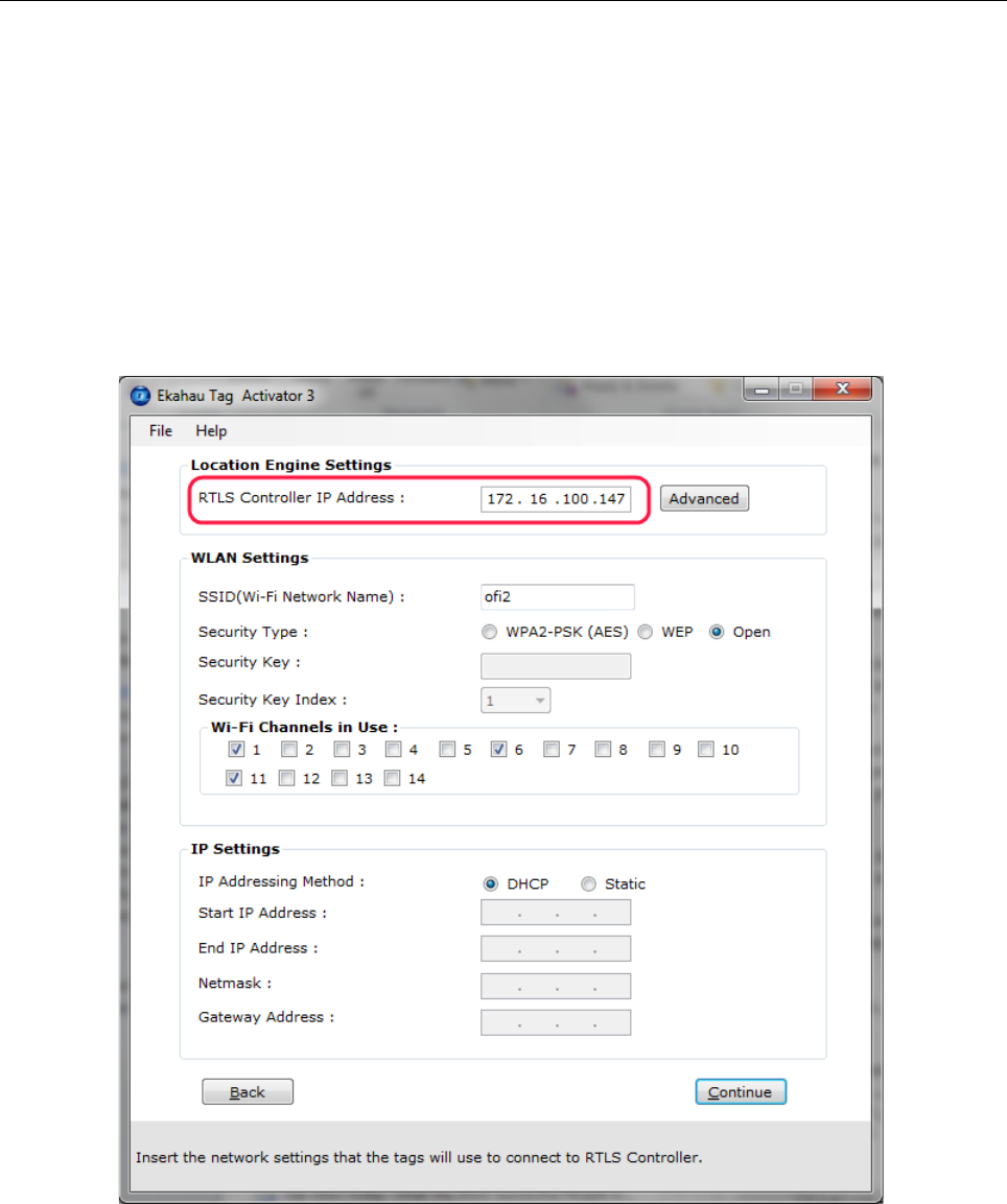
2.3.1 Configuring Ekahau RTLS Controller Settings
Input the IP address of the Ekahau RTLS Controller.
Figure 2.1. Specifying the Engine IP address and Maintenance interval
In case Engine Port, Maintenance port, and/or Maintenance IP needs to be changed, go to
"Advanced" mode. The (Periodic) Location Update Interval is set to 60 seconds and the (Periodic)
Maintenance Interval is set to 240 seconds by default , but shorter interval can be used if, for
instance, messages are sent frequently to the W4 tag.

7 Chapter 2. Initial Activation of the Tag
Figure 2.2. Specifying advanced Positioning Engine settings
Note
When activating the W4 tags, only an initial setup is required for the tag to associate with the
network. All settings can be set and changed from the Ekahau RTLS Controller. Ekahau Activator
3 only provides a set of basic settings.
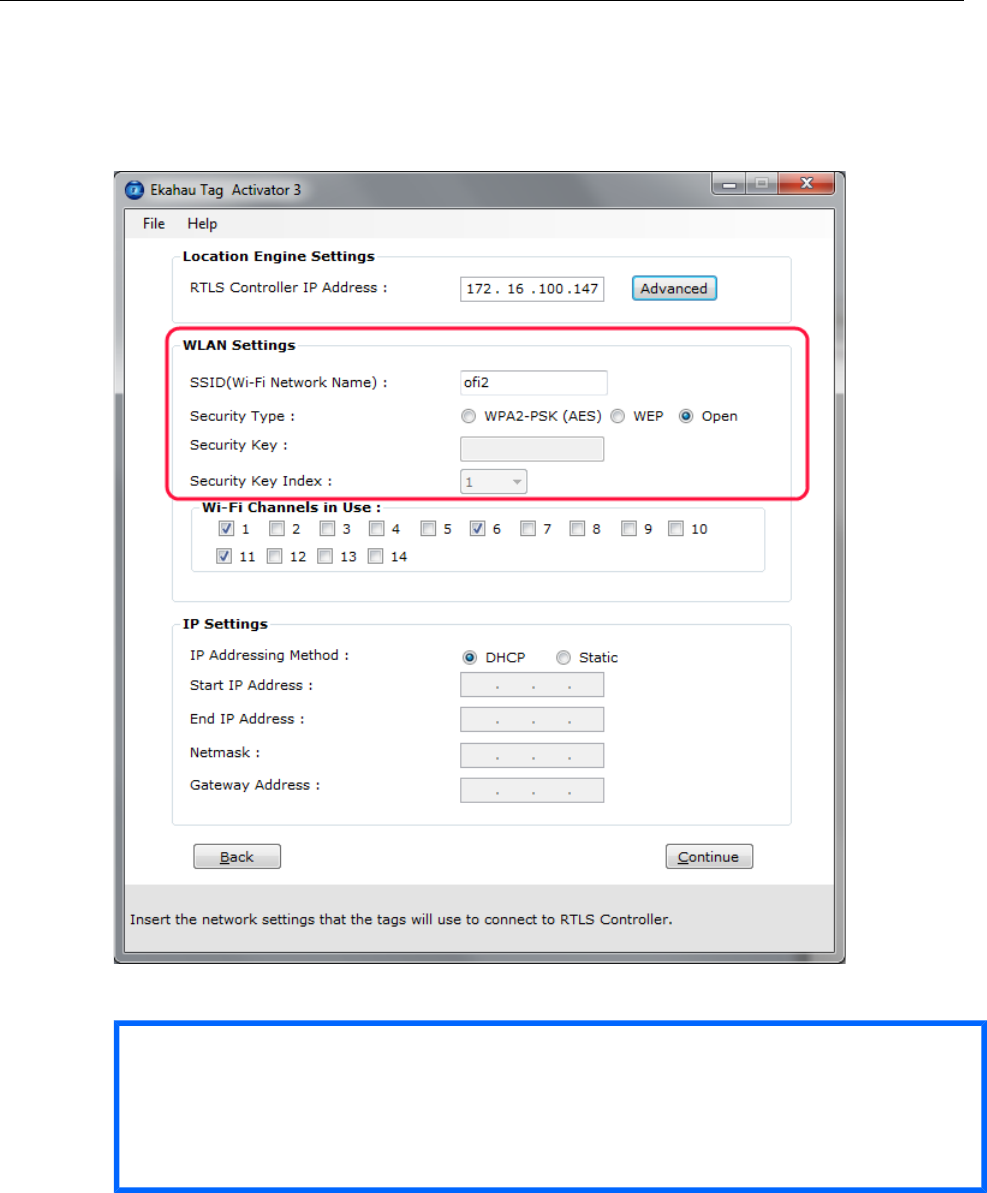
2.3.2 Configuring WLAN Settings
Input the Wi-Fi Network SSID and select the Encryption method used. If WEP 64/128 or WPA2-
PSK is used type in the network key as well. Normally, 1st Security Key Index (for WEP encrytion)
is used. Should you use key index other than the first one, please select the key index matching
the Security Key.
Chapter 2. Initial Activation of the Tag 8
Figure 2.3. Specifying Wi-Fi network settings
Tip
If WEP encryption is used the Activator automatically determines the key type and length from
what you type. WEP 64 require 5 Ascii characters or 10 hex digits, respectively WEP 128
requires 13 Ascii characters or 26 hex digits.
2.3.3 Configuring Wi-Fi Channels in Use
It is recommended to only select the channels used in you network. Activating the unused channels
will only reduce the battery lifetime of the tag. By default, the Scan Interval is 60 seconds. You
may also use shorter interval, but it will drain faster the battery of the tag. Alternatively you can
use longer Scan Interval and enable Motion Sensor through the Ekahau RTLS Controller after
activation. This way the tag will scan only when it is in use and moving.
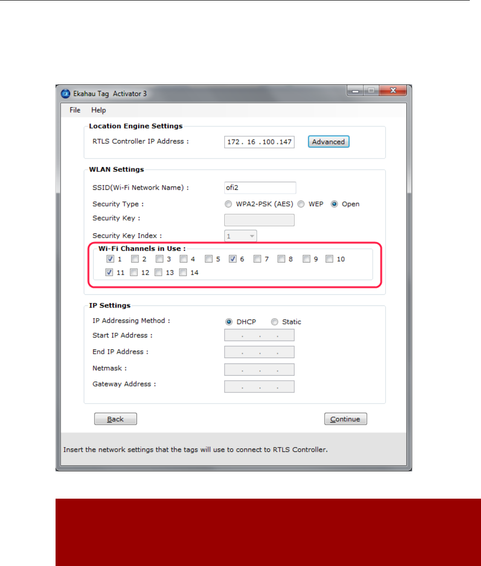
9 Chapter 2. Initial Activation of the Tag
Figure 2.4. Specifying the channels used in the network
Warning
Only use channels that really exists in your Wi-Fi network. Activating unnecessary channels
will reduce the tag's battery lifetime!
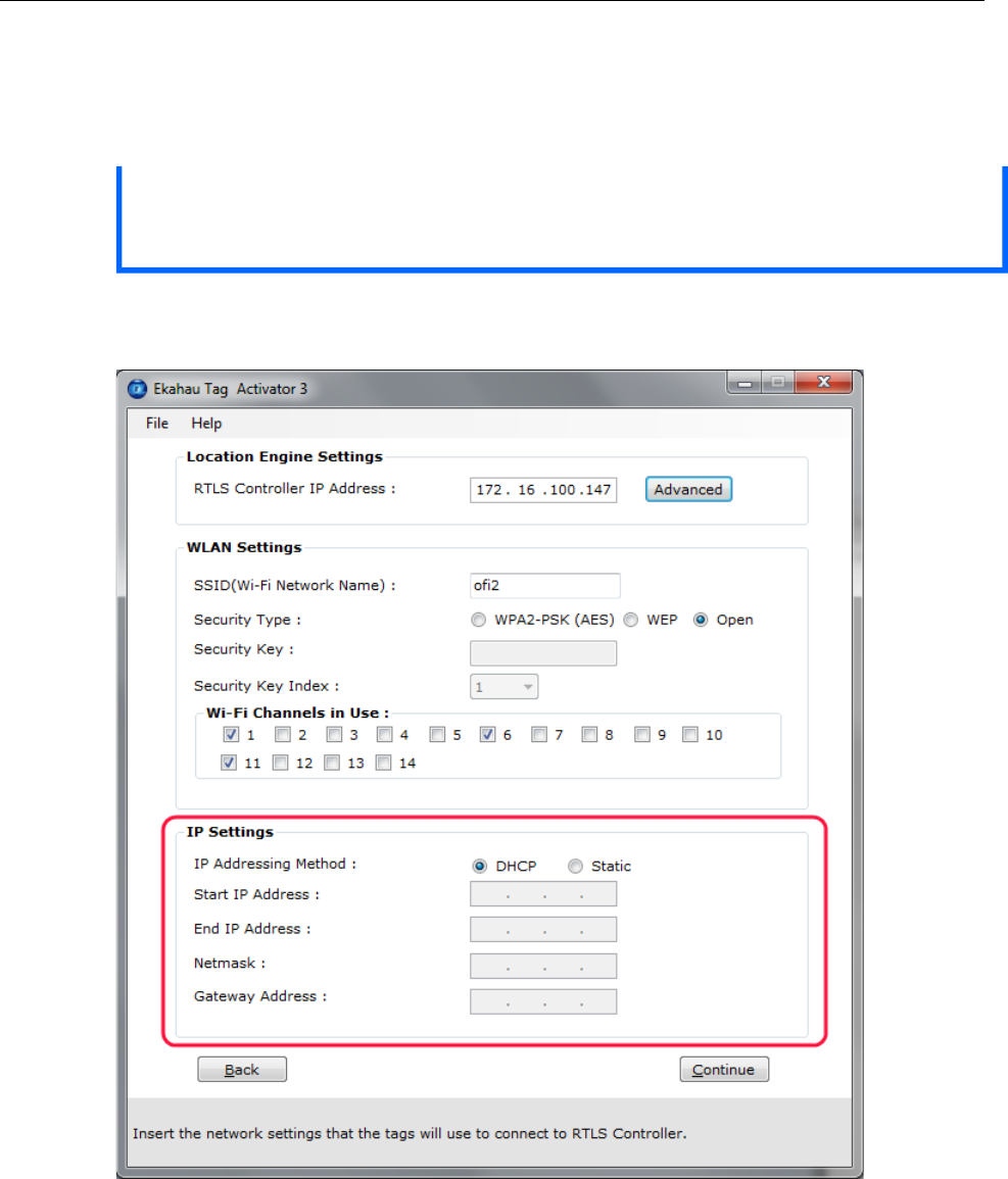
2.3.4 Configuring IP Settings
Check the IP settings. If DHCP is used nothing needs to be done. In case your network uses static
IP addressing, type in the IP address range to be used for the W4 tags, Netmask and Gateway
addresses.
Chapter 2. Initial Activation of the Tag 10
Tip
If you only activate a single tag and wish to use static IP setting, enter same IP address in
'Start IP Address' and 'End IP Address'.
Figure 2.5. Specifying IP settings
2.3.5 Activation
Press 'Continue' button when all settings are ready.
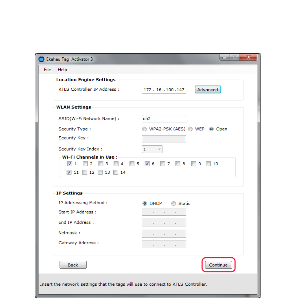
11 Chapter 2. Initial Activation of the Tag
Figure 2.6. When all the settings are done, you can start activating the tags
The Activation process has now started. The list of the activated tags will appead on the area
below.
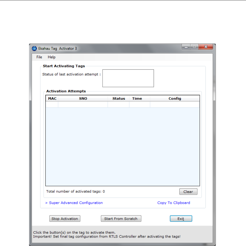
Chapter 2. Initial Activation of the Tag 12
Figure 2.7. The Activator is ready to start activating the tags
Put the tag in charger and while in charger, within three seconds press and hold the tag's button
at least five seconds to activate it. During this time tag's LED is red. If activation was successful
the tag will vibrate and the green LED will blink, with unsuccessful activation the LED blinks red.
After successful activation, the tag MAC address appears on the activation window, showing Ok
status. Repeat this for all the tags to be activated.
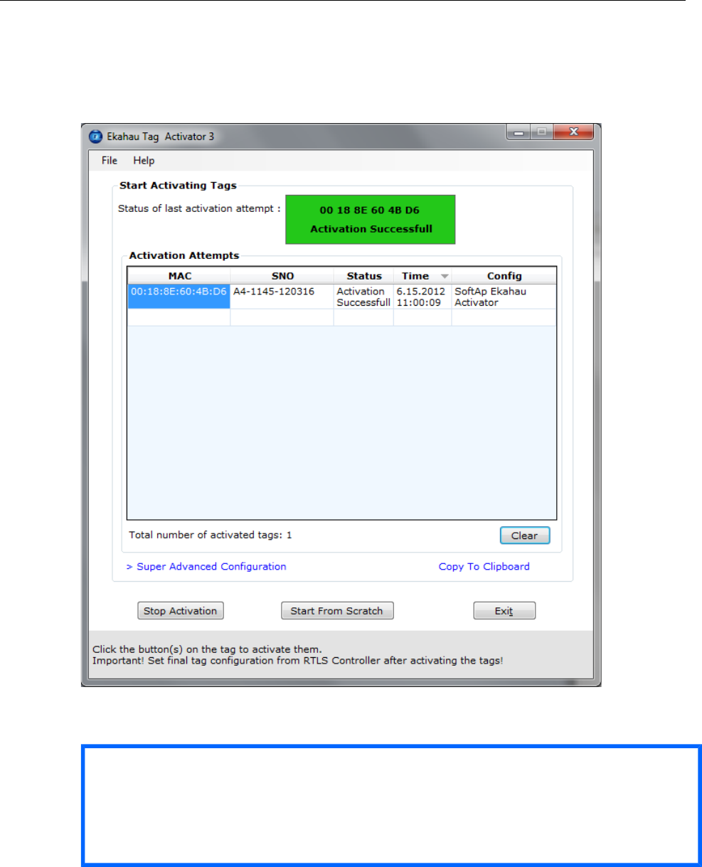
13 Chapter 2. Initial Activation of the Tag
Figure 2.8. The Activator has activated one tag
After completing activating the tags, click the 'Stop Activation' button and exit the activation window.
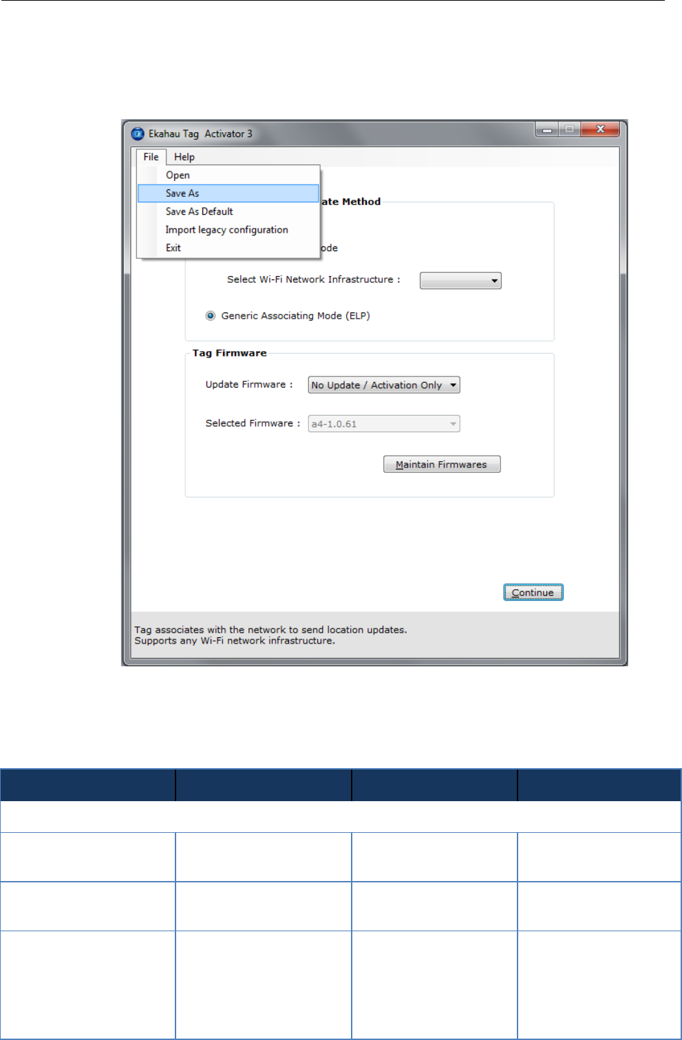
Tip
After you have finished the activation, you can save the configuration for future use from the
file menu. If you save the settings with 'Save As Default' the setup will be the default every
time the Activator is started.
Chapter 2. Initial Activation of the Tag 14
Figure 2.9. Saving the configuration for later use
2.3.6 List of Available Settings in the Activator
The list of available settings in the Activator:
Setting
Description
Values
Default Value
Positioning Engine settings
Engine IP
IP Address Ekahau RTLS
Controller
IP Address
0.0.0.0
Engine Port (UDP)
Port number of location
protocol port of ERC
Port Number
8552
Maintenance IP
IP Address of Ekahau
RTLS Controller, from
where TAG gets the set-
tings. Typically same as
the ERC IP
IP Address
0.0.0.0

15 Chapter 2. Initial Activation of the Tag
Setting
Description
Values
Default Value
Maintenance Port(UPD)
Port number of mainten-
ance protocol port of ERC
Port Number
8553
Maintenance interval
The interval of the peri-
odic maintenance calls in
seconds
0 - 63072000
10
Scan Settings
Scanning Interval
The interval of the peri-
odic location scans in
seconds
0 - 63072000
10
Scan Channels
Sets the channels that are
scanned
Enabled; Disabled
1-11 Enabled; 12-14
Disabled
WLAN Settings
SSID
Sets the Wi-Fi network
name -Service set identi-
fier
SSID=max 32 digits
default
Encryption
Selects if WEP encryp-
tion is used
No Encryption; WEP
64/128; WPA2-PSK
No Encryption
WEP
Sets the WEP pass-
phrase
ASCII: 5 or 13 charac-
ters
HEX: 10 or 26 hexa-
decimal numbers (0-f)
-
WEP Key Index
Sets the WEP Key index
used
1-4
1
WPA2-PSK
Sets the WPA2-PSK
encryption and pass-
phrase
8-63 ASCII characters
-
WPA-PSK
Not supported with W4
IP Settings
IP method
Defines the IP address
assigning method
DHCP; Static
DHCP
Static IP Settings
Address range
Sets the start and end
address of the range used
to assign the IP
addresses to the tags
when Static IP is used
IP address
0.0.0.0
0.0.0.0
Network mask
Tag netmask when static
addressing is used
IP address
0.0.0.0
IP gateway
IP network gateway when
static addressing is used
IP address
0.0.0.0

Chapter 2. Initial Activation of the Tag 16

17 Chapter 3. Configuration After Initial
Activation
3 Configuration After Initial Activation
The tag can be adjusted for each application and network settings by adjusting a set of parameters.
The parameters can be changed wirelessly after resetting the tag by using the Ekahau Activator
software or through Tag Configurations in Ekahau RTLS Controller.
Ekahau Activator is used for configuring the initial configuration settings that allows connecting
the tag to ERC over the network. After connection is established with ERC, all configurations can
be managed through Ekahau RTLS Controller.
3.1 Tag Configuration Settings in ERC Configs Page
In Ekahau RTLS Controller it is possible to create a configuration to a single tag or a group config-
uration to multiple tags. After the tags are activated, the configurations are applied to tags from
the Tags page. It is also possible to apply a configuration automatically to all new tags via the
Configs page. The list of available settings is in the following table:
Setting
Description
Values (Default underlined)
Networks
Scan Method
Allows using a vendor-specific
method for signal measurement.
The Generic method is vendor-
independent.
Generic, Aerohive, Aruba, Cisco
CCX, Extricom, Meru, Motorola,
Juniper blink
ELP Mixed Mode Flags
Allows location updates sent via
CCX/Ekahau Blink and button
presses etc. sent via ELP . CHOOSE
button shows the options. Recom-
mended not to use Mixed Mode with
Cisco MSE (or battery reporting will
be mixed up)
Can be set based on scan reason(s)
(button, safety switch, motion...)
SSID 1
SSID 1 name, Encryption, Pass-
phrase and WEP index.
See Configuring WLAN Set-
tings on page 7 for details
SSID 2
SSID 2 name, Encryption, Pass-
phrase and WEP index.
See Configuring WLAN Set-
tings on page 7 for details
SSID 2 Association
Sets whether tag attempts to asso-
ciate on T301BD SSID 2 network.
No association and scan only;
associate and scan; Disabled
Broadcast probe
Sets whether the tag uses broad-
cast probe when scanning.
Enabled; Disabled
Tag IP Settings
IP Setting
Sets the IP method used.
Use DHCP for each access point
Use DHCP once for all access
points
Preserve the IP-address that was
given by Activator
Positioning Engine

!
Chapter 3. Configuration After Initial 18
Activation !
Setting
Description
Values (Default underlined)
IP Address
Sets the ERC IP Address.
IP Address
Location update Port (UDP)
Port number of location protocol port
of ERC
Port Number
Maintenance port (UDP)
Port number of maintenance pro-
tocol port of EPE.
Port Number
General
Name
Name for the configuration set.
Free text
Description
Description for the configuration set.
Free text
Channels
Scan Channels
Sets the channels scanned during a
location scan.
1-11; 12 (EU); 13 (EU); 14 (Japan)
Periodic Location Update and Maintenance
Periodic Location Update
Enables or disables the periodic
location update.
Enabled; Disabled
Location Update Interval
Sets the interval for the periodic
location update.
The interval in Seconds, Minutes,
Hours or Days
Periodic Maintenance
Enables or disables the periodic
maintenance calls.
Enabled; Disabled
Maintenance Interval
The interval of the periodic mainten-
ance calls in seconds.
The interval in Seconds, Minutes,
Hours or Days
Sensors
Motion Sensor
Enables or disables motion sensors.
Disabled
Profile 1 (in motion for 8s)
Profile 2 (in motion for 4s)
Profile 3 (in motion for 2s)
Profile 4 (in motion for 1s)
Motion Update Method
Sets whether location updates are
sent periodically during the motion or
just when the motion starts and after
the movement has ended.
In-motion and after motion; After
motion
Motion Update Interval
Sets the interval for motion updates.
5s; 10s; 30s; 1min; 2min; 5min
Motion Stagnant Event
Enables or disables stagnant sens-
ing.
Enabled; Disabled
Motion Stagnant Treshold
Sets how long the tag has to remain
stagnant to produce a stagnant
event.
The threshold in Seconds, Minutes,
Hours or Days

!
19 Chapter 3. Configuration After Initial
Activation
Setting
Description
Values (Default underlined)
Location Beacon Sensor
Enable or disable the location beacon
sensor . In active mode a location
update is done immediately when the
tag notices a location beacon. In
passive mode the recent observed
location beacon ID is sent to EPE
only when location update is initiated
by other stimuli such as periodic or
motion wakeup.
Disabled, Passive Mode, Active
Mode
Advanced Scan Settings
Initial Scan Count
Number of scans the tag does on
each triggered scan despite the
triggering event. Used to improve the
accuracy in difficult conditions and
for rarely scanning applications
1 - 10
Note
1) Network wide DHCP enables roaming between sub-networks. With this setting the tag refreshes
its IP address whenever the tag associates with a new access point. It is not recommended to
use the feature, if not required, due to higher power consumption
Note
2) Using the Advanced Scan Settings need a careful consideration. The scanning consumes
a high amount of energy, and the more scanning is done the less battery life the tag has. Typ-
ically these parameters are used to improve accuracy in very difficult conditions or in cases the
tag otherwise would scan rarely.
3.2 Tag Actions Available in ERC Tags Properties Page
Setting
Description
Values (Default underlined)
User Data
Name
A user given name for tag
Free text
Custom
A custom note
Free text
Member of Groups
The groups the tag belong to
List of groups or "No Groups cre-
ated" if no groups exist. Go to
groups page to create groups.
Commands
Setting

!
Chapter 3. Configuration After Initial 20
Activation
Setting
Description
Values
LED / Vibration
Launches the alarm at the tag with
LEDs only or with vibration and
LEDs. The alarm duration can be
set.
LED; LED and Vibration
Duration: 10s; 1min; 10min; 30min;
1h; 2h
Manual Commands
Manual command or a list of com-
mands can be sent to a tag.
-
Set Config
A pre-defined config can be selected
and sent to tag(s)
A list of available configs. Go to
configs page to create tag configur-
ations.
Firmware Update
Firmware
Tag firmware can be updated. The
new firmware needs to be first
uploaded in the configs page
A list of available firmware updates
uploaded in ERC. The firmware
needs first to be uploaded into ERC,
this is done in configs page.
Create New Group
Group Name
New group is created and the tag is
included into this created group.
Free text
Address
Gateway
Sets the default gateway for the tag
IP Address
Delete
Delete
The tag is deleted from the system.
All statistics are cleared. The tag will
appear in the system again when it
report it's location next time.
-
Note
Note
Currently the W4's vibration is controlled and configured by using the same commands that are
used with the Buzzer. Remember that W4 tag does not have a buzzer alarm!

21 Chapter 4. Tag Operation
4 Tag Operation
4.1 Button Activated Location Update
In addition to periodic location updates, the tag can also be set to scan and update it's location
when any of the buttons is pressed. After a button press the tag scans immediately and sends the
results to ERC. The LEDs indicate the scan success or failure similarly as in the scan activated
by the wake up interval.
4.2 Maintenance Call
The W4 performs normal periodict Maintenance Calls. The interval of the Maintenance Calls can
be set during the initial activation or after the activation via Ekahau RTLS Controller.
The W4 tag does not perform button activated maintenance calls. Instead, when the button is
pressed, ERC will respond to the Location Update with ACK packet which can indicate if there is
pending Maintenance command message. If there is, the W4 will perform automatically Maintenance
Call.
4.3 De-activation / Resetting to Factory Settings
To deactivate the W4 tag, put it into charger and within three seconds press and hold the button
for at least ten seconds. During this period the LED will show orange light. The tag vibrates and
blinks the LED three times as green and red in turns when successfully reset.
4.4 Firmware Update
The tag firmware can be updated wirelessly using ERC. The firmware is uploaded to the tags from
the Tag Properties page or directly from Tags page in ERC. Follow instruction in the ERC User
Guide for updating the firmware.
Note
If the Tag battery level is below 10 % the FW update is not allowed. The corresponding error
code in ERC is TU. To update the firmware, please first recharge the battery and try again.
Note
W4 firmware update requires a new UDP port allocation from EPE (defaults to 8562). See
“Global Server Settings” page in EPE Config Utility.

Chapter 4. Tag Operation 22
4.5 Optimizing Battery Life
The W4 Wi-Fi tag uses an ultra-low power system-on-chip architecture that lowers the power
consumption to minimal. This enables running tags with same batteries for several years. However,
to get the maximum lifetime from your tags you should take care that your network and tag config-
uration supports all possible power save features.
The principal in optimizing battery life is to determine the maximum interval for location updates,
still sufficient for the use case, to minimize the amount of time the tag is active.
Recommendations for optimizing battery lifetime:
● Scan only channels that are in use in your network. Typically, because of overlap of channels,
there are only 3 or 4 channels in use from the 11 (or 13/14) available.
● Use single SSID whenever possible. Using multiple SSIDs requires additional network scans
and decreases battery lifetime.
● When using dynamic IP addressing tune the DHCP server to provide very long lease times
for tags.
● W4 tag supports roaming between subnetworks. This feature renews tag’s IP address whenever
the access point association changes. Since renewing IP addresses consumes large amounts
of energy, it is strongly recommended not to use the network wide dynamic addressing feature
if it is not needed.
● Tune the wake up settings to match your application needs. More frequent updates lower the
battery lifetime.
4.6 Turning off the W4 Tag
The W4 tag can only be turned off by resetting the tag to factory settings which is explained in
chapter De-activation / Resetting to Factory Settings on page 21. To continue using the tag after
resetting, you have to re-activate it following the instructions explained in chapter Activation Pro-
cedure on page 5.
4.7 Charging the W4 tag
The W4 tag is delivered with the battery charged to a storage charge, and it is recommended to
fully charge the batteries before first time activating the tag. To ensure the tag battery is full,
please put the tag in to a charger for 4 hours.
The tag will give a notification when the tag battery is low. Connect the charger and the LED will
show red light during the charging. after the tag is fully charged the LED will turn green. If the tag
battery is completely empty, the tag will automatically turn off. After a charger is connected, the
tag will automatically return to it's normal function, maintaining last settings.
The Ekahau supported adapters are
1. Ekahau W4 Single Charger
2. Ekahau W4 Multi Charger
The W4 tags are attached to the Single Charger as illustrated below.
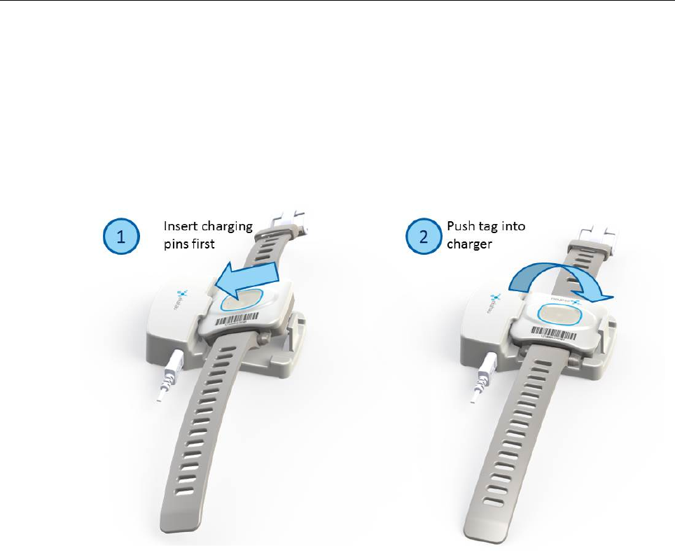
23 Chapter 4. Tag Operation
Figure 4.1. W4 insertion in the Single Charger.
1. Slide the tag with the connectors downward to the charging slot.
2. Press the top of the tag towards the clip until it clicks in the charging position and the charging
light turns on (under the button of the tag). Note that if the battery is fully discharged, it may take
up to 15 minutes for the charging light to turn on.
Deattach the tag from the charger by gently pulling the clip away from the tag until the tag is
released from the charging position.
The W4 tags are attached to the Multi Charger as illustrated below.
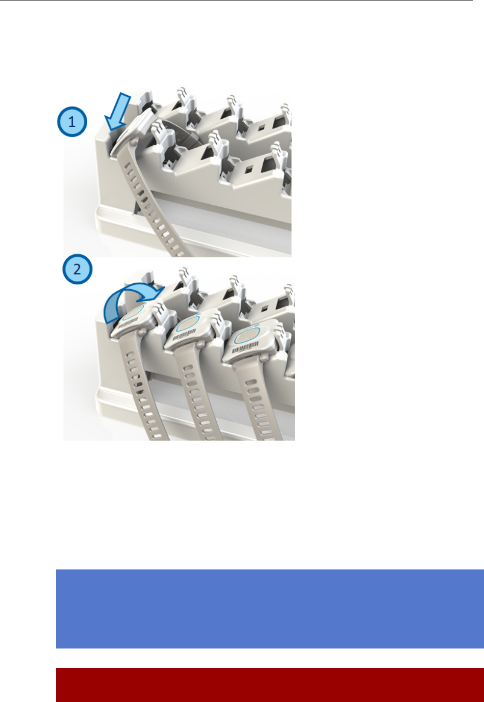
Chapter 4. Tag Operation 24
Figure 4.2. W4 insertion in the Multi Charger.
1. Slide the tag with the connectors downward to the charging slot.
2. Press the top of the tag towards the clip until it clicks in the charging position and the charging
light turns on (under the button of the tag). Note that if the battery is fully discharged, it may take
up to 15 minutes for the charging light to turn on.
Detach the tag from the charger by gently pulling the clip away from the tag until the tag is
released from the charging position.
Note
In case the tag battery is completely empty, typically when left empty and uncharged for several
days, it may take a long time for the tag even to turn on the orange led. Just connect the charger
and leave the tag to recharge overnight.
Warning

25 Chapter 4. Tag Operation
Only use Ekahau supported adapters for charging the tags.
Warning
Recharge the tag only in room temperature conditions, 0 °C - 40°C (32 °F - 104 °F). Recharging
the tag in too cold or too hot conditions may damage the tag.

Chapter 4. Tag Operation 26

27 Chapter 5. Technical specifications
5 Technical specifications
5.1 General
● Outside Dimensions: 51.5 x 50 x 17.5mm, 2 x 1.9 x 0.7in
● Weight: 31g / 1.09oz
● Power: Re-Chargeable Lithium Polymer battery
● Charging with 5 VDC, 500 mA max
● One button with call button functionality
● Vibration alarm for alerting the person wearing
● Built-in 3D accelerometer for detecting different states of movement (Currently not in use)
● One red/green/orange status indication LED
● Operating Temperature: 0 to 50 ºC / 32 to 122 ºF, battery lifetime is lower on the low and high
end of the temperature range.
● Storage Temperature: -40 to 60 ºC / -40 to 140 ºF, battery lifetime is lower on the low and
high end of the range. Storage in room temperature is recommended.
● Humidity: From 20 % to 95 % non-condensing, relative humidity
● Environmental Protection: Dust and water proof enclosure
5.2 Wi-Fi
● Supported IEEE Standards: 802.11b/g/n (g/n in CCX or Ekahau blink mode only)
● Modulation Scheme: Direct Sequence Spread Spectrum (DSSS)
● Media Access: CSMA/CA
● Frequency Ranges:
○ 2.400 - 2.4835 GHz (USA, Canada, Europe)
○ 2.400 - 2.497 GHz (Japan)
● Supported Networking Protocols: UDP/IP, DHCP or static addressing
● Security: 64/128-bit WEP key and WPA2-PSK authentication
● Antenna Type: Internal 2.4GHz SMD omni-directional ceramic multilayer
● Maximum Antenna Gain: +1.8 dBi
5.3 Operating Ranges from an Access Point
● Open Space: 100m/330ft at 11Mb, 150m/500ft at 2Mb
● Typical Office: 40m/140ft at 11Mb, 60m/200ft at 2Mb
5.4 Care and Maintenance
● Keep the tag dry. Precipitation, humidity and all types of liquids or moisture can contain min-
erals that will corrode electronic circuits.
● Do not use or store the tag in dusty, dirty areas. Its moving parts can be damaged.
● Do not store the tag in hot areas. High temperatures can shorten the life of electronic devices,
damage batteries, and warp or melt certain plastics.
● Do not store the tag in cold areas. When it warms up (to its normal temperature), moisture
can form inside, which may damage electronic circuit boards.
● The operating temperature of the tag is 0 to 50 ºC (32 - 122 ºF). Do not operate the tag outside
this temperature range.

Chapter 5. Technical specifications 28
● Do not drop, knock or shake the tag. Rough handling can break internal circuit boards.
● Do not use harsh chemicals, cleaning solvents, or strong detergents to clean the tag.
● Do not paint the tag. Paint can clog the moving parts, affect the radio communication and
prevent proper operation.
● Use a soft, clean and dry cloth to clean the tag.
● Use only the supplied antenna. Unauthorized antennas, modifications or attachments could
damage the tag and may violate regulations governing radio devices.

29 Chapter 6. Certifications
6 Certifications
6.1 FCC Rules
This device complies with Part 15 of the FCC Rules. Operation is subject to the following two
conditions:
(1) device may not cause harmful interference, and
(2) device must accept any interference received, including interference that may cause
undesired operation.
FCC ID of this device is: TA7-T301-W1
Note: This equipment has been tested and found to comply with the limits for a Class B digital
device, pursuant to part 15 of the FCC Rules. These limits are designed to provide reasonable
protection against harmful interference in a residential installation. This equipment generates uses
and can radiate radio frequency energy and, if not installed and used in accordance with the
instructions, may cause harmful interference to radio communications. However, there is no
guarantee that interference will not occur in a particular installation. If this equipment does cause
harmful interference to radio or television reception, which can be determined by turning the
equipment off and on, the user is encouraged to try to correct the interference by one or more of
the following measures:
● Reorient or relocate the receiving antenna
● Increase the separation between the equipment and receiver
● Connect the equipment into an outlet on a circuit different from that to which the receiver is
connected
● Consult the dealer or an experienced radio/TV technician for help
Changes or modifications not expressly approved by the party responsible for compliance could
void the user's authority to operate the equipment.
6.1.1 Réglementations FCC
Les changements ou modifications non expressément approuvés par Ekahau, Inc. peuvent annuler
votre droit d.utiliser cet appareil aux termes des réglementations FCC.
Cet appareil est conforme à la section 15 des règlements FCC sur les appareils numériques de
classe B.
Fonctionnement soumis aux conditions suivantes :
(1) Cet appareil ne doit pas causer d’interférences nuisibles.
(2) Cet appareil doit accepter toute autre interférence reçue, y compris les interférences susceptibles
d'entraîner un fonctionnement non désiré.
6.2 CE Marking
This device has been tested to meet the Electromagnetic Compatibility (EMC) and User safety
requirements in accordance with following standards: EN55022, EN55024, EN301489-1,
EN301489-17, EN300328, EN62479 and EN60950 for the CE Declaration of Conformity (DoC).

9 Chapter 5. Certifications
6.3 Industry Canada Statements for Portable Devices
Section 7.1.3 of RSS-GEN
Operation is subject to the following two conditions:
1) this device may not cause interference, and
2) this device must accept any interference, including interference that may cause undesired
operation of the device.
Le fonctionnement de ce système est assorti aux deux conditions suivantes :
1 L’appareil ne peut causer d’interférences nuisibles, et
2 L’appareil doit accepter les interférences reçues, y compris celles qui pourraient nuire à son
fonctionnement.
Section 7.1.2 of RSS-GEN
"Under Industry Canada regulations, this radio transmitter may only operate using an antenna of a type
and maximum (or lesser) gain approved for the transmitter by Industry Canada. To reduce potential
radio interference to other users, the antenna type and its gain should be so chosen that the equivalent
isotropically radiated power (e.i.r.p.) is not more than that necessary for successful communication."
"Conformément à la réglementation d'Industrie Canada, le présent émetteur radio peut fonctionner avec
une antenne d'un type et d'un gain maximal (ou inférieur) approuvé pour l'émetteur par Industrie
Canada. Dans le but de réduire les risques de brouillage radioélectrique à l'intention des autres
utilisateurs, il faut choisir le type d'antenne et son gain de sorte que la puissance isotrope rayonnée
équivalente (p.i.r.e.) ne dépasse pas l'intensité nécessaire à l'établissement d'une communication
satisfaisante."

Chapter 6. Certifications 30

31 Chapter 7. Limited Warranty
7 Limited Warranty
Ekahau warrants that the Tags will operate in accordance with and substantially conform to their
published specifications when shipped or otherwise delivered to the end user and for a period of
1 year thereafter, provided, however, that Ekahau does not warrant any claim or damage under
this Warranty if such claim or damage results from:
1. Misuse, neglect, accident or improper installation or maintenance of the Tags,
2. Tags that have been altered, modified, repaired or tampered with by anyone other than Ekahau,
3. Use of the Tags not in compliance with their respective documentation, user manuals,
instructions, and any usage restrictions contained therein, including, but not limited to, the
provisions relating to the environment and ranges where the tags must be used, or
4. Accident, fire, power failure, power surge, or other hazard.
Otherwise, the Tags are sold AS IS. In no event does Ekahau warrant that the Tags are error free
or that end user will be able to operate the Tags without problems or interruptions.
End User is responsible for using the Tags within their specifications as contained in the Docu-
mentation.
8 Disposing
F
igure 8.1. The Ekahau W4 Wi-Fi tag is non-recyclable
Note
The Ekahau W4 Wi-Fi tag is non-recyclable. Product has non-replaceable battery
which contains hazardous materials. To dispose the product, send it to a specialized
company that is capable of handling electronic waste. Alternatively, you can return
product back to Ekahau who will dispose it for you.
!

Chapter 8. Disposing 32