Aiphone GT Installation_EN_17.03.03 B System Installation Manual ENG
User Manual: Aiphone GT System Installation Manual Instructions
Open the PDF directly: View PDF ![]() .
.
Page Count: 52
SERVICE MANUAL
GT SYSTEM
Standard & Expanded System
INSTALLATION MANUAL
Thank you for selecting Aiphone for your communication needs. Please read this manual carefully before installation, and
keep this in a safe place for future reference.
Please note that images and illustrations depicted in this manual may differ from the actual product.
The following manuals (in multi languages) of the GT system are also available from our website
http://www.aiphone.net/.
* The site can be accessed directly by reading the QR code on the right.
• Operation manual
• Installation manual
• Setting manual
• Quick start installation guide
• Aiphone GT Setup Tool for Windows
[QR code]
- 2 -
PRECAUTIONS
WARNING
(Negligence could result in death or serious injury.)
1. Do not dismantle or alter the unit. Fire or electric shock could result.
2. Do not connect any power source other than specifi ed to terminals +,
- nor install two power supplies in parallel to single input. Fire or
damage to the unit could result.
3. Do not connect any terminal on the unit to AC power line. Fire or
electric shock could result.
4. For power supply, use Aiphone power supply model or model specifi ed
for use with system. If non-specifi ed product is used, fi re or malfunction
could result.
5. Voltage is applied to parts within the equipment. Do not touch any parts
that are not associated with the installation, wiring, or connection.
Electric shock could result.
6. If any abnormality (i.e., smoke, unusual smell or unusual noise) is
sensed from the unit, or the unit falls or gets broken, unplug the unit or
turn off the breaker immediately. Fire or electric shock could result.
CAUTION
(Negligence could result in injury to people or damage to
property.)
1. Do not install or make any wire terminations while power supply is
plugged in. It can cause electrical shock or damage to the unit.
2. Before turning on power, make sure wires are not crossed or shorted.
Fire or electric shock could result.
3. When mounting the unit on wall, install the unit in a convenient location,
but not where it could be jarred or bumped. Injury could result.
4. Do not install the unit in locations subject to frequent vibration or
impact. It may fall or tip over, resulting in damage to the unit or personal
injury.
5. Be sure to perform a call test or check the chime volume with the
handset on the hook. If you operate the hook switch with the handset on
your ear, a sudden call etc. may cause damage to your ear.
6. Do not place your ear close to the speaker during use as it could cause
hearing damage.
Precautions for mounting
1. Observe the following restrictions for mounting entrance stations.
• Do not mount the entrance station so that it faces obliquely upward. The
rain water may go inside and it may damage the unit.
• Do not block the bottom of entrance station by caulking.
2. Do not install the unit in any of the following locations. Fire, electric shock,
or unit trouble could result.
• Places under direct sunlight.
• Places near heating equipment or a boiler that varies in temperature.
• Places where dust, oil, chemicals or hydrogen sulfi de are present.
• Places where moisture and humidity extremes are present, such as
bathrooms, cellars, greenhouses, etc.
• Places where the temperature is quite low, such as inside a refrigerated
area or in front of an air conditioner.
• Places with steam or smoke (near heating or cooking surfaces).
• Places subject to sulfur, such as hot springs.
• Places near the shore or exposed to the direct sea breeze.
3. Do not install this unit in any of the following locations where lighting or
the ambient environment could impact the display on the video monitor due
to the characteristics of the door station's camera.
• Locations where is bright as the sky is shown widely behind the caller
• There is a white wall behind the caller
• Locations subject to direct sunlight or strong lighting
4. When using a fl uorescent light that shines around the camera in the 50Hz
area, the screen colors may variously change as color rolling or fl ickering.
Please block off the light or use the inverter fl uorescent lamp.
5. For running cables, separate them for audio/video and door release and
keep them more than 10cm (3-15/16") away from each other.
6. When using an existing wiring, depending on the type of wiring, it may not
operate the system. Please check and change it in advance.
7. Do not use the impact driver for mounting. Damage to the unit could result.
General Precautions
1. Keep the intercom wires more than 30cm (12") away from AC 100-240V
wiring. AC induced noise and malfunction could result.
2. When installing and using the system, please consider the privacy and
portrait rights of users and visitors. Aiphone shall not be held responsible
for violation or privacy or other statutory rights. (The protection of privacy
and statutory rights is the responsibility of the customer.)
3. Install the units, which will not be operated, in an area that will be
accessible for future inspections, repairs, and maintenance.
4. Be sure to install an entrance station vertically. If it is installed horizontally,
rainwater may get into the unit causing a malfunction.
5. For maintenance or after-sales service, make sure to provide the setting
data to the customer.
6. Do not put an obstacle such as a foliage plant where monitoring is done by
a human body detection sensor.
Notices
• Do not install the unit close to an electrical appliance or water heater using
a dimmer or inverter, a remote controller of fl oor heating, etc. Failure to do
so may generate a noise causing a malfunction of the unit.
• In areas where broadcasting station antennas are close by, intercom system
may be affected by radio frequency interference.
• When warm indoor air fl ows into the unit, dew condensation may be caused
by a temperature difference between indoors and outdoors. It is
recommended to cover openings on the unit such as cable incoming holes
to avoid condensation.
• Using a mobile phone or professional-use radio equipment such as walkie-
talkie close to the system may cause a malfunction.
Prohibited Do not dismantle unit Keep unit away from water Be sure to follow the instruction
- 3 -
Table of Contents
PRECAUTIONS ......................................................................................................................................... 2
1 SYSTEM CONFIGURATIONS
1-1 Standard system confi guration & capacity ....................................................................................... 4
1-2 Expanded system confi guration & capacity ...................................................................................... 5
1-3 Residential/tenant station confi guration ............................................................................................ 6
1-4 Lift control system confi guration (for expanded system only) ......................................................... 8
1-5 Wiring distance ................................................................................................................................. 9
2 COMPONENTS
2-1 Entrance station (modular type) ...................................................................................................... 12
2-2 Entrance station (all-in-one type) .................................................................................................... 14
2-3 Bus control unit etc. ........................................................................................................................ 14
2-4 Residential/tenant station, sub residential/tenant station ................................................................ 15
2-5 Door station ..................................................................................................................................... 16
2-6 Guard station ................................................................................................................................... 16
2-7 Lift control adaptor ......................................................................................................................... 16
3 MOUNTING
3-1 Mounting locations ......................................................................................................................... 17
3-2 Cable ............................................................................................................................................... 17
3-3 Mounting positions and image view area ....................................................................................... 18
3-4 Entrance station (modular type) ...................................................................................................... 19
3-5 Entrance station (all-in-one type) .................................................................................................... 21
3-6 Bus control unit, 4-way video junction unit, lift control adaptor and power supply ...................... 22
3-7 Residential/tenant station ................................................................................................................ 23
3-8 Door station (for residential/tenant station) .................................................................................... 26
3-9 Guard station ................................................................................................................................... 27
4 WIRING
4-1 Standard system .............................................................................................................................. 28
4-2 Guard station ................................................................................................................................... 30
4-3 Entrance station ............................................................................................................................... 31
4-4 Residential/tenant trunk .................................................................................................................. 34
4-5 Expanded system ............................................................................................................................ 40
4-6 Lift control system (for expanded system only) .............................................................................42
4-7 Option connector ............................................................................................................................. 43
5 SETTINGS
5-1 Switch settings ................................................................................................................................ 45
5-2 Switch settings (for residential/tenant stations only) ...................................................................... 48
6 CHECK FOR INSTALLATION ......................................................................................................... 49
6-1 Finding a proper "grounding point" for power supply .................................................................... 49
6-2 Checking "ground fault" with tester ................................................................................................ 50
REGULATIONS ....................................................................................................................................... 51
WARRANTY ............................................................................................................................................ 52
- 4 -
PS24
PS24 PS24
PS24 PS24
PS24
*2
2
B
A
C
3
E
D
F
5
K
J
L
8
U
T
V
4
H
G
I
6
N
M
O
1
0
9
Y
X
W
Z
7
R
Q
P
S
2
B
A
C
3
E
D
F
5
K
J
L
8
U
T
V
4
H
G
I
6
N
M
O
1
0
9
Y
X
W
Z
7
R
Q
P
S
2
B
A
C
3
E
D
F
5
K
J
L
8
U
T
V
4
H
G
I
6
N
M
O
1
0
9
Y
X
W
Z
7
R
Q
P
S
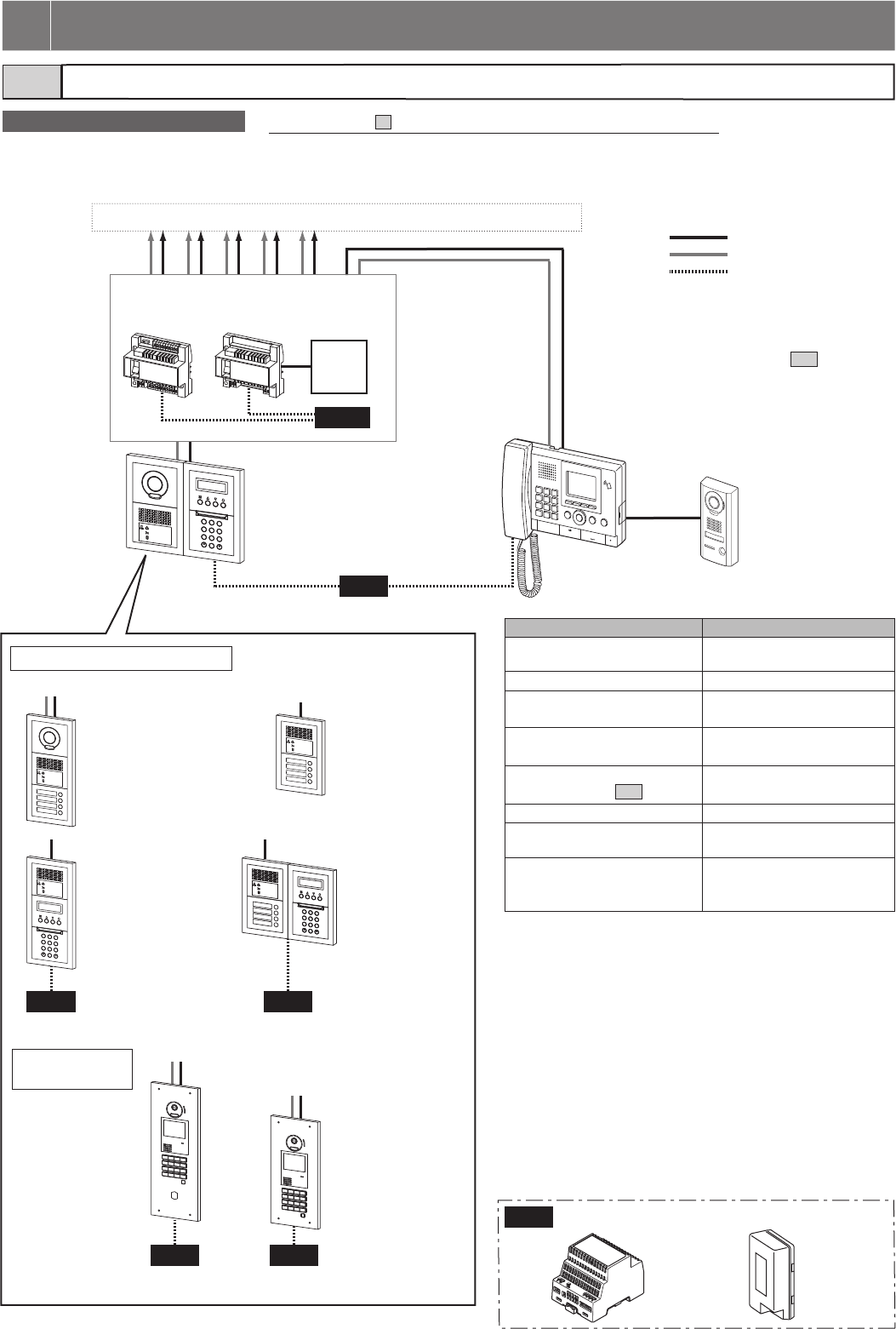
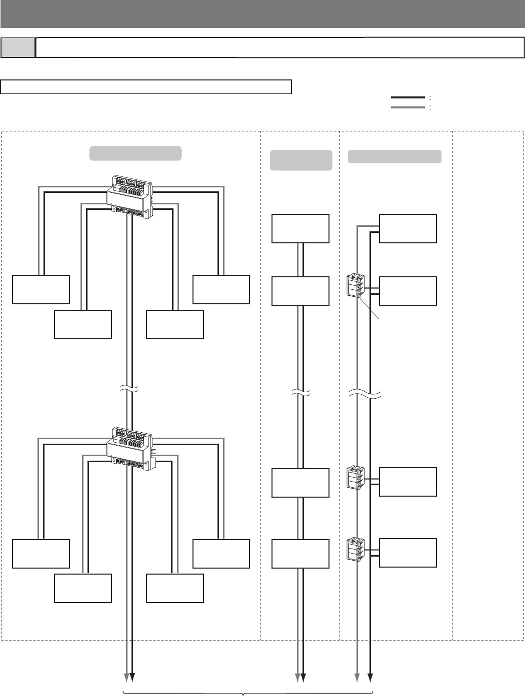
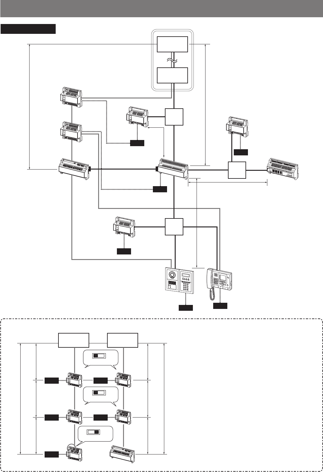
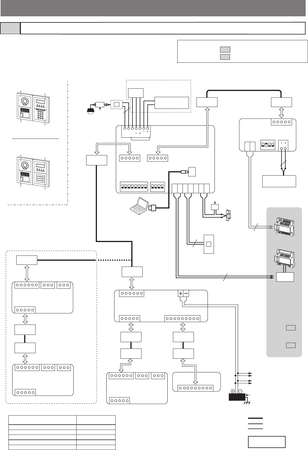
This system is constructed using 2 wires for audio and 2 wires for video and requires minimal work for installation. A maximum of 6 video trunk
lines can be used from the video bus controller and audio signal lines use a distribution point from the bus controller. Audio systems can also be
confi gured.
DP
: Audio signal line
: Video signal line
: Power supply line
Video bus
control unit
GT-VBC
Bus control
unit
GT-BC
DP: Distribution Point
( Not provided by Aiphone except
for Europe and North America.)
Guard station
GT-MKB-N
Entrance station
Audio/video + 10 key type
e.g.) GT-VB + GT-DB(-V, -VN) +
GT-NSB + GT-10K
Audio/video + direct select
e.g.) GT-VB +
GT-DB(-V, -VN) +
GT-SW
Audio + 10 key
e.g.) GT-DB(-V, -VN) +
GT-NSB + GT-10K
Audio + direct select
e.g.) GT-DB(-V, -VN) +
GT-SW
Audio + direct
select + 10 key
e.g.) GT-DB(-V, -VN)
+ GT-NSB +
GT-10K +
GT-SW
GT-DMB-LVN
(Magnetic-loop and VIGIK-linked enabled)
GT-DMB-N
Device Capacity
Entrance station Max. 5 (max. 3 per trunk from the
DP) *3 *4
Guard station (GT-MKB-N) Max. 2
Residential/tenant station Max. 48 (max. 25 per trunk from
the DP) *5
Residential/tenant stations in the
same residence/tenant
Max. 4 *6
4-way video junction unit
(GT-4Z, see section 1-3 .)
Max. 6 per residential/tenant
trunk
Bus control unit (GT-BC) 1 required
Video bus control unit (GT-VBC
[STD])
Max. 1
Sub residential/tenant station
(GT-2H-L, GT-2H)
Max. 3 (connectable to the
residential/tenant station GT-2C-L
or GT-2C only)
*3: If GT-DB-V, GT-DB-VN or an external door release button is
connected to an entrance station that includes GT-SW, a
maximum of 3 entrance stations can be connected to the system.
*4: Up to 3 entrance stations can be connected per audio signal line
from the DP. If GT-DB-V or GT-DB-VN is used in an entrance
station, the maximum number of entrance stations is 2.
*5: The maximum is 100 stations with GT-1D only.
(GT-1D: Max. 50 stations per trunk)
*6: Max. 4 under the following conditions only:
• GT-1A or GT-1D × Max. 4
• GT-1C7(-L) × 1 + GT-1A or GT-1D × Max. 3
• GT-1M3(-L) × 1 + GT-1A or GT-1D × Max. 3
• GT-1M3(-L) × 2 + GT-1A or GT-1D × Max. 2
• GT-2C(-L) × Max. 4
Standard system confi guration & capacity1-1
Outline of standard system
Entrance station (modular type)
Entrance station
(all-in-one type)
Residential/tenant trunks 1 to 5 [max. 48 stations (max. 25 per trunk) ] *1
1 SYSTEM CONFIGURATIONS
* Refer to section 4 "WIRING" for details about wiring and connection.
*1: Refer to section 1-3 for details
about residential/tenant station
confi gurations.
*2: Make sure that a power supply is
shared between GT-BC and
GT-VBC.
Video door station
JO-DV
PS-2420
PS-2420S
PS-2420UL
PS-2420BF
PS-2420DM
PS24
Power supply
- 5 -
PS-2420
PS-2420S
PS-2420UL
PS-2420BF
PS-2420DM
PS24
2
B
A
C
3
E
D
F
5
K
J
L
8
U
T
V
4
H
G
I
6
N
M
O
1
0
9
Y
X
W
Z
7
R
Q
P
S
2
B
A
C
3
E
D
F
5
K
J
L
8
U
T
V
4
H
G
I
6
N
M
O
1
0
9
Y
X
W
Z
7
R
Q
P
S
PS24
PS24 PS24 PS24 PS24
DPDP
PS24 PS24
PS24 PS24 PS24 PS24
*2 *2 *2 *2
*3
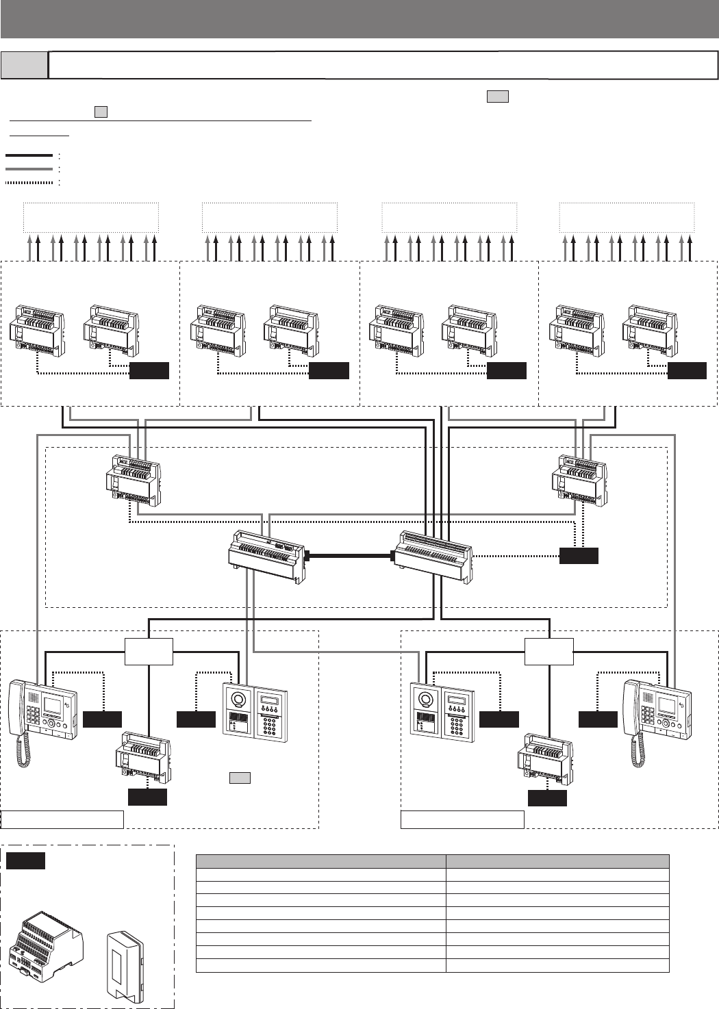
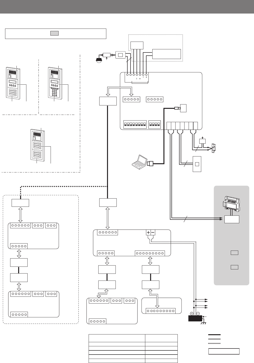
[Max. 125 stations
(max. 25 per trunk) ] *1
Power supply
Sub trunk line 1A Sub trunk line 1B Sub trunk line 2A Sub trunk line 2B
Audio signal line
Video signal line
Power supply line
Expanded video
bus control unit
GT-VBX Expanded bus
control unit
GT-BCXB-N
Video bus
control unit
GT-VBC GT-VBC GT-VBC GT-VBC
Bus control
unit
GT-BC GT-BC GT-BC GT-BC
GT-BC
GT-VBC
[EXP]
GT-VBC
[EXP]
GT-BC
Entrance station
* See section
1-1 for various
types.
Entrance station GT-MKB-N
Guard
station
GT-MKB-N
Device Capacity
Entrance station Max. 16 (max. 8 per common trunk 1 & 2) *4
Guard station (GT-MKB-N) Max. 4 (max. 2 per common trunk line 1 & 2)
Residential/tenant station Max. 500 *5
Residential/tenant stations per sub trunk line Max. 125 (max. 25 per trunk)
Residential/tenant stations in the same residence (Same as standard system)
Sub residential/tenant station (GT-2H-L, GT-2H) (Same as standard system)
Bus control units per common trunk line (GT-BC)
1 required
Bus control units per sub trunk line (GT-BC) 1 required
*4: Up to 3 entrance stations can be connected per audio signal line from the DP within common trunk line 1&2. If
GT-DB-V or GT-DB-VN is used in an entrance station, the maximum number of entrance stations is 2.
*5: This includes guard stations connected to the entrance stations by the Hand-shaking link setting.
Expanded system confi guration & capacity1-2
The wiring of the sub trunk line is the same as the standard system.
* Refer to section 4 "WIRING" for details about wiring and
connection.
*1: Refer to section 1-3 for details about residential/tenant
station confi gurations.
*2: Make sure that a power supply is shared between GT-BC and
GT-VBC. Also, a power supply must not be shared between
trunk lines (including sub and common trunk lines).
*3: Make sure that a power supply is shared between GT-BCXB-N
and GT-VBC.
Common trunk line 1 Common trunk line 2
DP: Distribution Point
(Not provided by Aiphone except
for Europe and North America.)
[Max. 125 stations
(max. 25 per trunk) ] *1 [Max. 125 stations
(max. 25 per trunk) ] *1
[Max. 125 stations
(max. 25 per trunk) ] *1
- 6 -
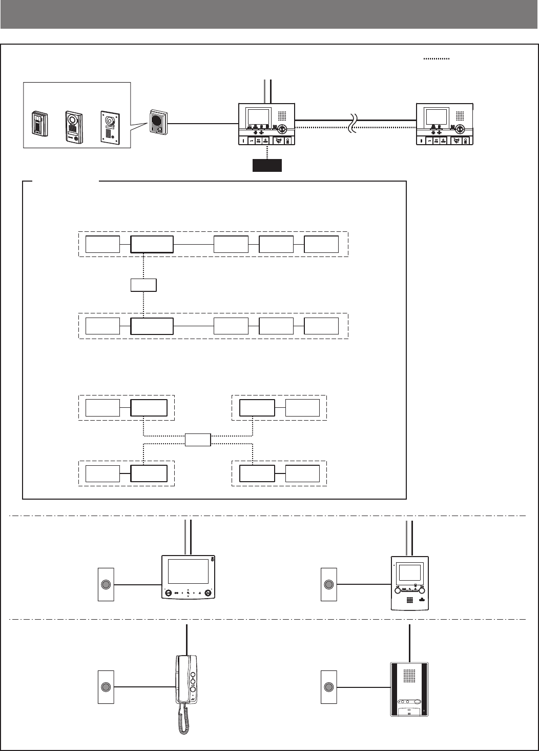
Audio signal line
Video signal line
4-way video junction unit
GT-4Z
GT-4Z
GT-1Z
GT-1Z
Trunk line 1
Residential/
tenant st.
Residential/
tenant st.
Residential/
tenant st.
Residential/
tenant st.
Residential/
tenant st.
Residential/
tenant st.
Residential/
tenant st.
Residential/
tenant st.
Residential/
tenant st.
Residential/
tenant st.
Residential/
tenant st.
Residential/
tenant st.
Residential/
tenant st.
Residential/
tenant st.
Residential/
tenant st.
Residential/
tenant st.
To each control unit
Trunk line 3 Trunk line
4 to 6
* Select one of
the same
wiring methods
as trunk lines 1
to 3.
Trunk line 2
GT-4Z wiring method Loop wiring
method GT-1Z wiring method
For wiring from the control units to each residence/tenant, GT-4Z wiring method, loop wiring method, or GT-1Z wiring method is possible.
NOTE: Mixing different wiring methods on the same trunk line is not allowed.
Residential/tenant station confi guration1-3
Video 1-zone
divider
GT-1Z
- 7 -
PS24
PS24
AIPHONE
JF-DVF
JK-DA JK-DV JK-DVF
PS24
Residential/tenant station
GT-2C-L, GT-2C
Residential/tenant station
GT-1C7, GT-1C7-L
Sub residential/tenant station
GT-2H-L, GT-2H
Residential/tenant station
GT-1M3, GT-1M3-L
Residential/tenant station
GT-1D Residential/tenant station
GT-1A
Residence/tenant (for GT-2C-L or GT-2C)
Video door station
Power supplies
[When sub residential/tenant stations are connected]
[When sub residential/tenant stations are not connected]
Residence/
tenant 1
Residence/
tenant 1
Residence/
tenant 3
Residence/
tenant 2
Residence/
tenant 2
Residence/
tenant 4
Door
station
Door
station
Door
station
GT-2C(-L)
GT-2C(-L) GT-2C(-L)
GT-2H(-L) GT-2H(-L) GT-2H(-L)
GT-2C(-L)
GT-2C(-L) GT-2C(-L)
GT-2H(-L) GT-2H(-L) GT-2H(-L)
Door
station
Door
station
Door
station
One power supply can be used to power 2 residences/tenants if sub stations are used.
One power supply can be used to power up to 4 residences/tenants if no sub stations are used.
Door station
or doorbell
GT-D
Doorbell Doorbell
Doorbell Doorbell
Residence/tenant (for GT-1C7,
GT-1C7-L, GT-1M3, and GT-1M3-L)
Residence/tenant
(for GT-1D and GT-1A)
: Power supply line
- 8 -
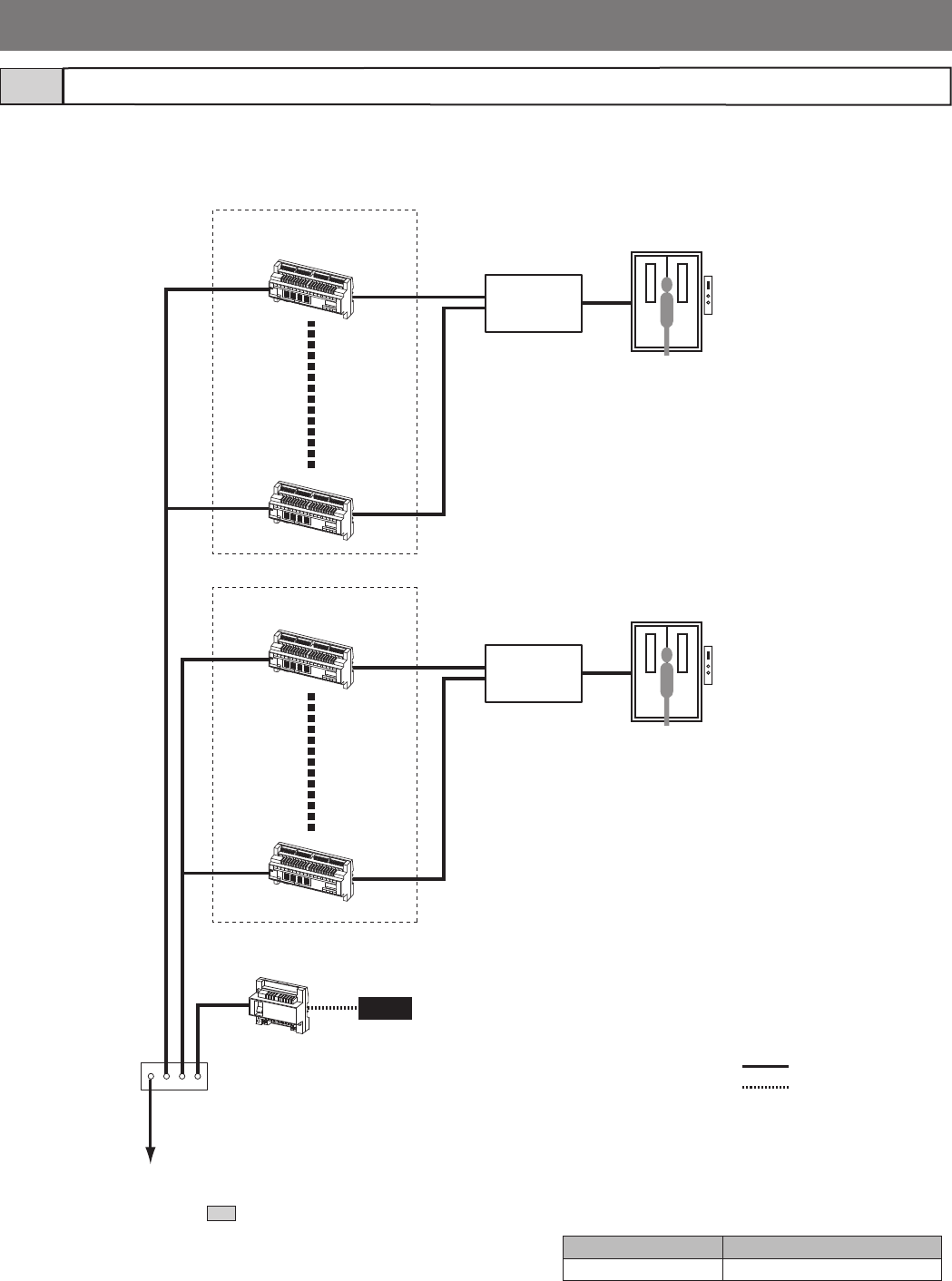
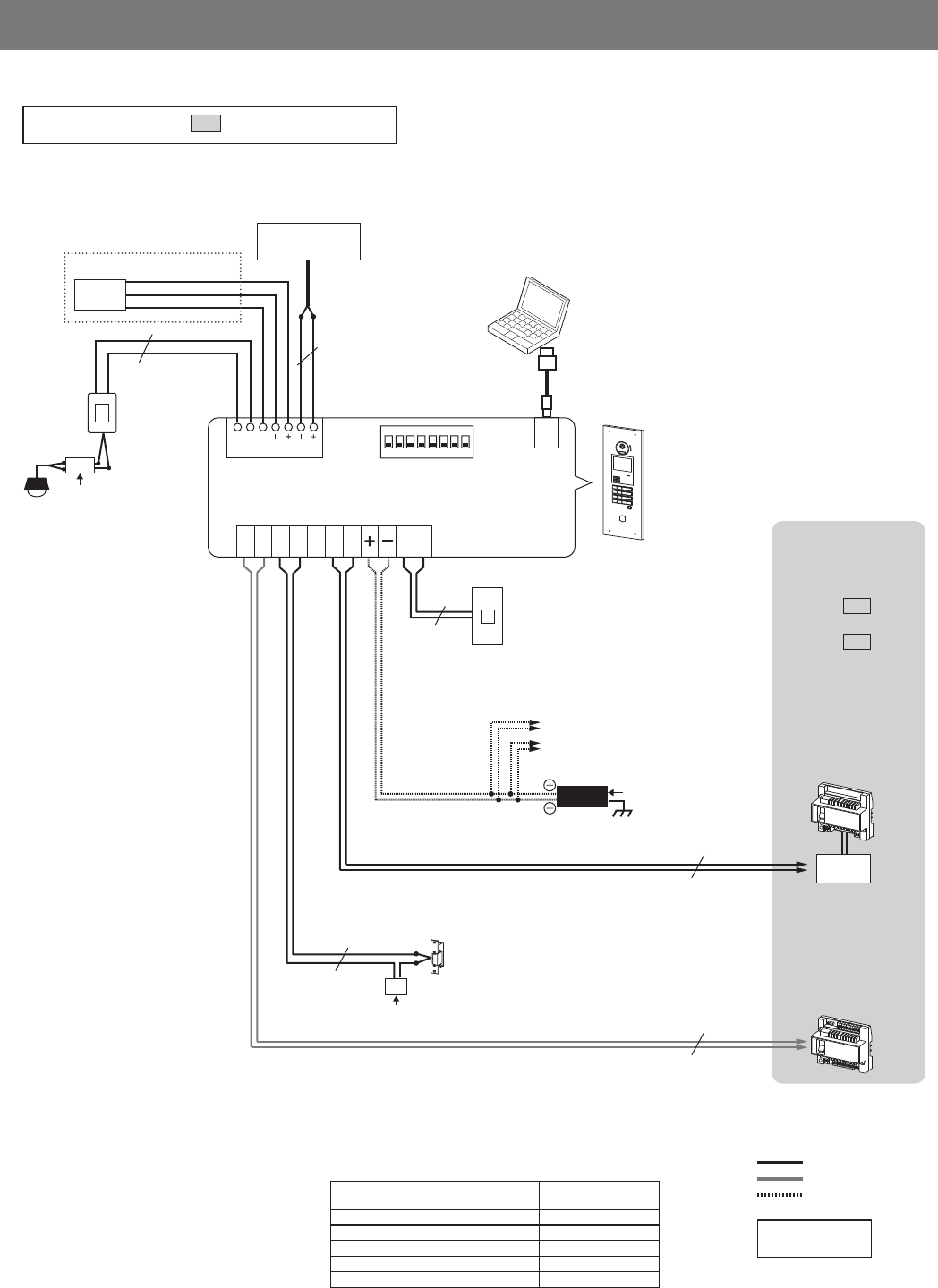
Lift control system confi guration (for expanded system only)1-4
DP
PS24
Lift control adaptor 9 to16
GTW-LC
Lift control adaptor 1 to 8
GTW-LC
Lift controller
(third party product)
Trunk 2
Trunk 1
Lift
(third party product)
Lift
(third party product)
Lift controller
(third party product)
To the expanded bus control unit
GT-BCXB-N
(See section 1-2 .)
Bus control unit
GT-BC
Device Capacity
Lift control adaptor Max. 16 (max. 8 per trunk)
DP: Distribution Point
(Not provided by
Aiphone except for
Europe and North
America.)
: Signal line
: Power supply line
- 9 -
PS24
PS24
PS24
[1]
[2]
[3]
[10]
[17]
[15]
[16]
[13]
[4]
[6]
[8]
[12]
[14]
GT-VBC(*1) GT-BC
DP
GT-MKB-N JO-DV
GT-4Z
GT-1Z
[9]
[23] [23]
[24]
[23] [23]
PS24
[18]
[22]
[22]
[16]
[19]
[20]
[21]
[5]
[24]
2
B
A
C
3
E
D
F
5
K
J
L
8
U
T
V
4
H
G
I
6
N
M
O
1
0
9
Y
X
W
Z
7
R
Q
P
S
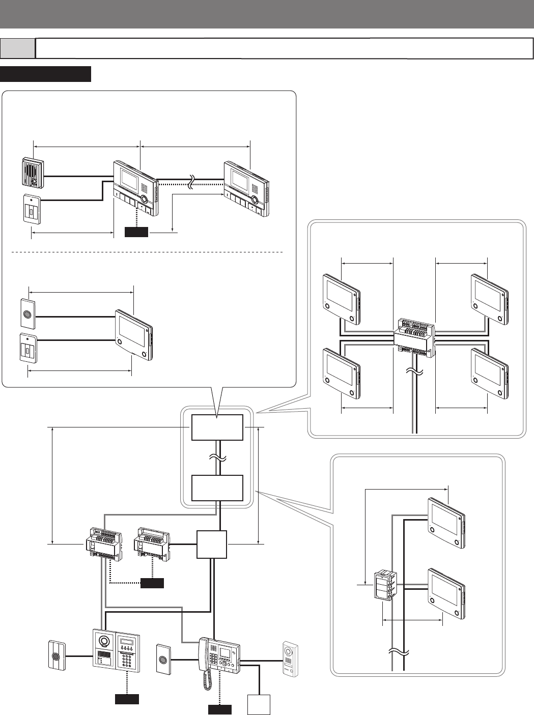
Standard system
Residence/tenant (GT-2C(-L) + GT-2H(-L) only)
[Station to peripheral devices]
[GT-4Z to residential/tenant stations]
(e.g. GT-1C7)
[GT-1Z to residential/tenant stations
(e.g. GT-1C7)]
Residence/tenant (e.g. GT-1C7(-L))
Entrance station
External
door release
button
Doorbell
Monitor/DVR
(third party product)
Residence/
tenant
Residence/
tenant
Wiring distance1-5
Emergency
alarm switch
Emergency
alarm switch
Door station
Doorbell
- 10 -
2
B
A
C
3
E
D
F
5
K
J
L
8
U
T
V
4
H
G
I
6
N
M
O
1
0
9
Y
X
W
Z
7
R
Q
P
S
PS24
PS24
PS24
PS24
[1]
[4] [10][2]
[1]
[1]
[8]
[8]
[9]
[9]
[12]
[25]
[26]
[28]
[27]
[7]
[29]
[31]
[30]
GT-BC
GTW-LC
GT-BCXB-N
GT-VBX
GT-MKB-N
PS24
[14]
GT-BC
[11]
DP
DP
DP
GT-VBC(*1)
GT-VBC(*1)
PS24
[8]
GT-BC
Expanded system
Entrance station
PS24
PS24
PS24
[7]
[7]
[27]
[7]
[7]
[7]
GT-VBX
GT-VBC
GT-VBC
GT-VBC
PS24
PS24
GT-VBC
GT-VBC
MODE
EXPAND
STANDARD
MODE
EXPAND
STANDARD
MODE
EXPAND
STANDARD
The GT-VBC can be used as an extension adaptor (2
units per sub trunk line).
To do so, set the setting switch MODE to "EXPAND".
Even if two units are used as extension adaptors (MODE:
EXPAND), the wiring distance to the farthest residential/
tenant station from the GT-VBC (MODE: STANDARD) or
GT-VBX is limited to 300 m (980').
300 m
(980')
300 m
(980')
Standard system Expanded system
Residence/
tenant
Residence/
tenant
Residence/
tenant
Residence/
tenant
(*1): When using the GT-VBC as an extension adaptor

- 11 -
The table below shows the maximum wiring distances between devices.
Wire diameter
Wiring distance
0.65 mm
(22 AWG)
0.8 mm
(20 AWG)
1.0 mm
(18 AWG)
[1] GT-BC - DP *2 3 m (10') 5 m (16') 5 m (16')
[2] Entrance station - DP *2 150 m (490') 300 m (980') 300 m (980')
[3] Entrance station - GT-VBC 150 m (490') 300 m (980') 300 m (980')
[4] GT-MKB-N - DP *2 150 m (490') 300 m (980') 300 m (980')
[5] DP *2 - farthest residential/tenant station (includes system with GT-4Z or
GT-1Z) 150 m (490') 300 m (980') 300 m (980')
[6] GT-VBC - farthest residential/tenant station (includes system with GT-4Z or
GT-1Z) *4 100 m (330') 150 m (490') 150 m (490')
[7] GT-VBC (MODE: STD / EXP) - GT-VBC (MODE: EXP) 100 m (330') 150 m (490') 150 m (490')
[8]GT-BC - power supply *3 3 m (10') 5 m (16') 5 m (16')
[9] GT-VBC - power supply *3 3 m (10') 5 m (16') 5 m (16')
[10] GT-VBC - farthest GT-MKB-N 100 m (330') 150 m (490') 150 m (490')
[11] GT-BCXB-N - farthest GTW-LC 150 m (490') 300 m (980') 300 m (980')
[12] Entrance station - power supply *3 150 m (490') 300 m (980') 300 m (980')
[13] Entrance station - external door release button 10 m (33') 15 m (49') 15 m (49')
[14] GT-MKB-N - power supply *3 100 m (330') 150 m (490') 150 m (490')
[15] GT-MKB-N - JO-DV 30 m (100') 50 m (165') 50 m (165')
[16] Residential/tenant station/GT-MKB-N - doorbell 5 m (16') 10 m (33') 10 m (33')
[17] GT-MKB-N - monitor/DVR Coaxial cable 15 m (49')
[18]Door station - GT-2C-L, GT-2C 50 m (165') 100 m (330') 100 m (330')
[19] GT-2C-L, GT-2C - farthest GT-2H-L, GT-2H 50 m (165') 100 m (330') 100 m (330')
[20] GT-2C-L, GT-2C - power supply 25 m (82') 50 m (165') 75 m (245')
[21] GT-2H-L, GT-2H - power supply 50 m (165') 100 m (330') 150 m (490')
[22] Residential/tenant station - emergency alarm switch 10 m (33') 15 m (49') 15 m (49')
[23] GT-4Z - residential/tenant station 30 m (100') 50 m (165') 50 m (165')
[24] GT-1Z - residential/tenant station 10 m (33') 15 m (49') 15 m (49')
[25] GT-BCXB-N - power supply *3 3 m (10') 5 m (16') 5 m (16')
[26] GT-BCXB-N - GT-BC 150 m (490') 300 m (980') 300 m (980')
[27] GT-VBX - GT-VBC (MODE: EXP) 100 m (330') 150 m (490') 150 m (490')
[28]Entrance station, GT-MKB-N - GT-BCXB-N 150 m (490') 300 m (980') 300 m (980')
[29] Entrance station - GT-VBX 150 m (490') 300 m (980') 300 m (980')
[30] GT-BCXB-N - farthest residential/tenant station (includes system with GT-4Z
or GT-1Z) 150 m (490') 300 m (980') 300 m (980')
[31] GT-VBX - farthest residential/tenant station (includes system with GT-4Z or
GT-1Z) *4 150 m (490') 300 m (980') 300 m (980')
GT-DB-V, GT-DB-VN, GT-DMB-LVN - (VIGIK) *5 5 m (16') 10 m (33') 10 m (33')
Standard system audio [R1, R2] total wiring distance *1 1650 m (5400') 2500 m (8200') 2500 m (8200')
Expanded system audio [R1, R2] total wiring distance per common line
(maximum 2 trunk lines) 1650 m (5400') 2500 m (8200') 2500 m (8200')
Expanded system audio [R1, R2] total wiring distance per common line
(maximum 4 trunk lines) 1650 m (5400') 2500 m (8200') 2500 m (8200')
Lift control total wiring distance from GT-BCXB-N (including GTW-LC) 1650 m (5400') 2500 m (8200') 2500 m (8200')
GT-RY - residential/tenant station 5 m (16') 10 m (33') 10 m (33')
GT-2C-L, GT-2C - external monitor 1.5 m (5') 3 m (10') 3 m (10')
Entrance station - surveillance camera Coaxial cable 15 m (50')
*1: The wiring distances from a door station to a GT-2C-L or GT-2C are not included in the total wiring distance.
*2: DP = Distribution Point (Not provided by Aiphone except for Europe and North America.)
*3: When powering two or more devices with one power supply, separate the cables near the power supply.
*4: The wiring distance between GT-VBX or GT-VBC (STANDARD) to the farthest residential/tenant station by using GT-VBC (EXPAND) is 300 m (980')
regardless of the wiring method.
*5: A shielded wire is required.
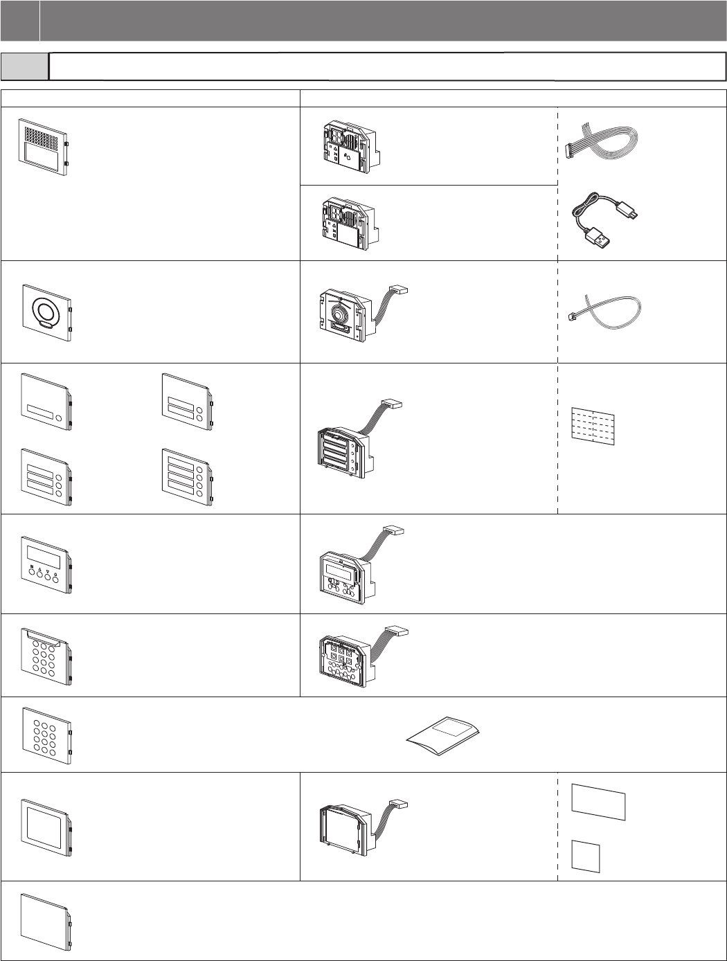
- 12 -
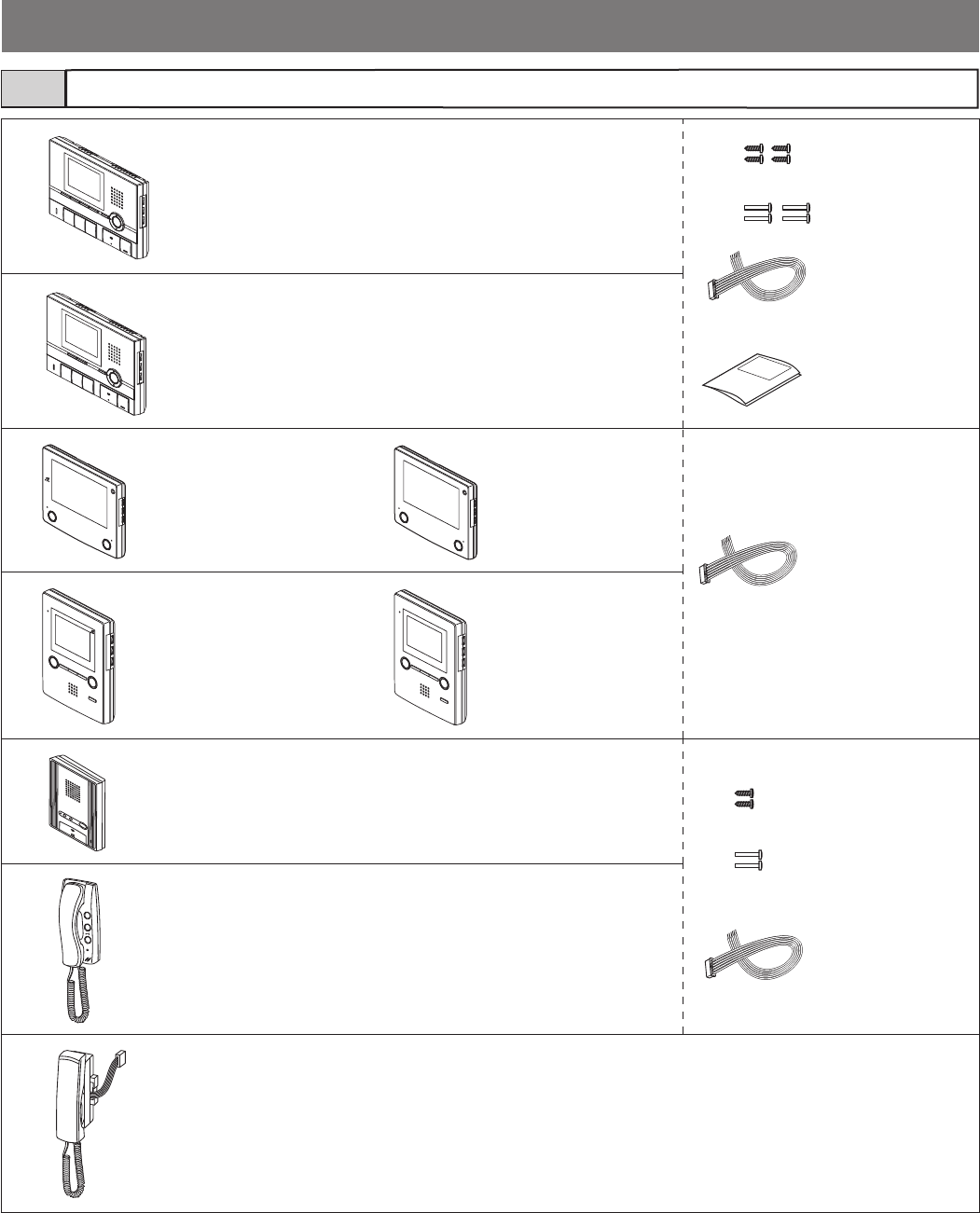
2-1
Panel Module
Audio panel
GT-DBP
Audio module
GT-DB-VN (VIGIK and NFC
capable)
Audio module
• GT-DB-V (VIGIK capable)
• GT-DB
Camera module panel
GT-VP
Camera module
GT-VB
1-call button
panel
GF-1P
2-call button
panel
GF-2P Call switch module
GT-SW Name card
3-call button
panel
GF-3P
4-call button
panel
GF-4P
Name scrolling module
panel
GT-NSP-L
Name scrolling module
GT-NSB
10 key module panel
GF-10KP
10 key module
GT-10K
Access control keypad module with panel
GT-AC Installation & operation manual
Address
module panel
GF-AP
Address module
GT-AD
Address card
Address cover
Blank panel
GF-BP
* All the above products except GT-DB-V include the Chinese RoHS paper.
2 COMPONENTS
USB cable
A-Micro B type
(1 m)
Option
connector
(2-pin)
Entrance station (modular type)
Option
connector
(7-pin)
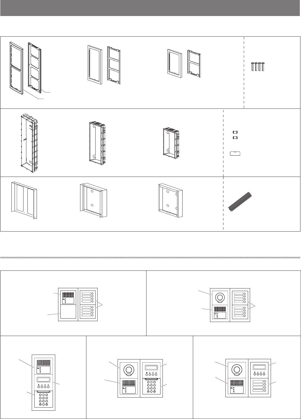
- 13 -
Mounting parts
Combination examples
4-module back box
GT-4B
3-module back box
GF-3B
2-module back
box
GF-2B
Joint pipe
Mounting gauge
Rain hood
GT-nH
Hooded surface-
mount box
GT-nHB
Surface-mount
box
GF-nBA
* A number appears in place of n.
GT-DB(-V, -VN) +
GT-DBP
GT-SW +
GF-4P
GF-BP
GT-SW +
GF-4P
GT-DB(-V, -VN) +
GT-DBP
GT-VB +
GT-VP
Audio only, Direct select type (8 stations)
Audio only, Name scrolling & 10 key
type
Audio/video, Direct select type (8 stations)
Audio/video, Name scrolling & direct select
type (4 stations)
Audio/video, Name scrolling & 10 key type
(Front frame)
4-module front
frame
GT-4F
(Mounting bracket)
3-module front
frame
GF-3F
2-module front
frame
GF-2F Screws
Weather stripping
2
B
A
C
3
E
D
F
5
K
J
L
8
U
T
V
4
H
G
I
6
N
M
O
1
0
9
Y
X
W
Z
7
R
Q
P
S
GT-DB
(-V,-VN) +
GT-DBP
GT-VB +
GT-VP GT-NSB +
GT-NSP-L
GT-10K +
GF-10KP
GT-SW +
GF-4P
GT-DB
(-V, -VN) +
GT-DBP
GT-VB +
GT-VP GT-NSB +
GT-NSP-L
2
B
A
C
3
E
D
F
5
K
J
L
8
U
T
V
4
H
G
I
6
N
M
O
1
0
9
Y
X
W
Z
7
R
Q
P
S
GT-DB
(-V, -VN) +
GT-DBP
GT-NSB +
GT-NSP-L
GT-10K +
GF-10KP
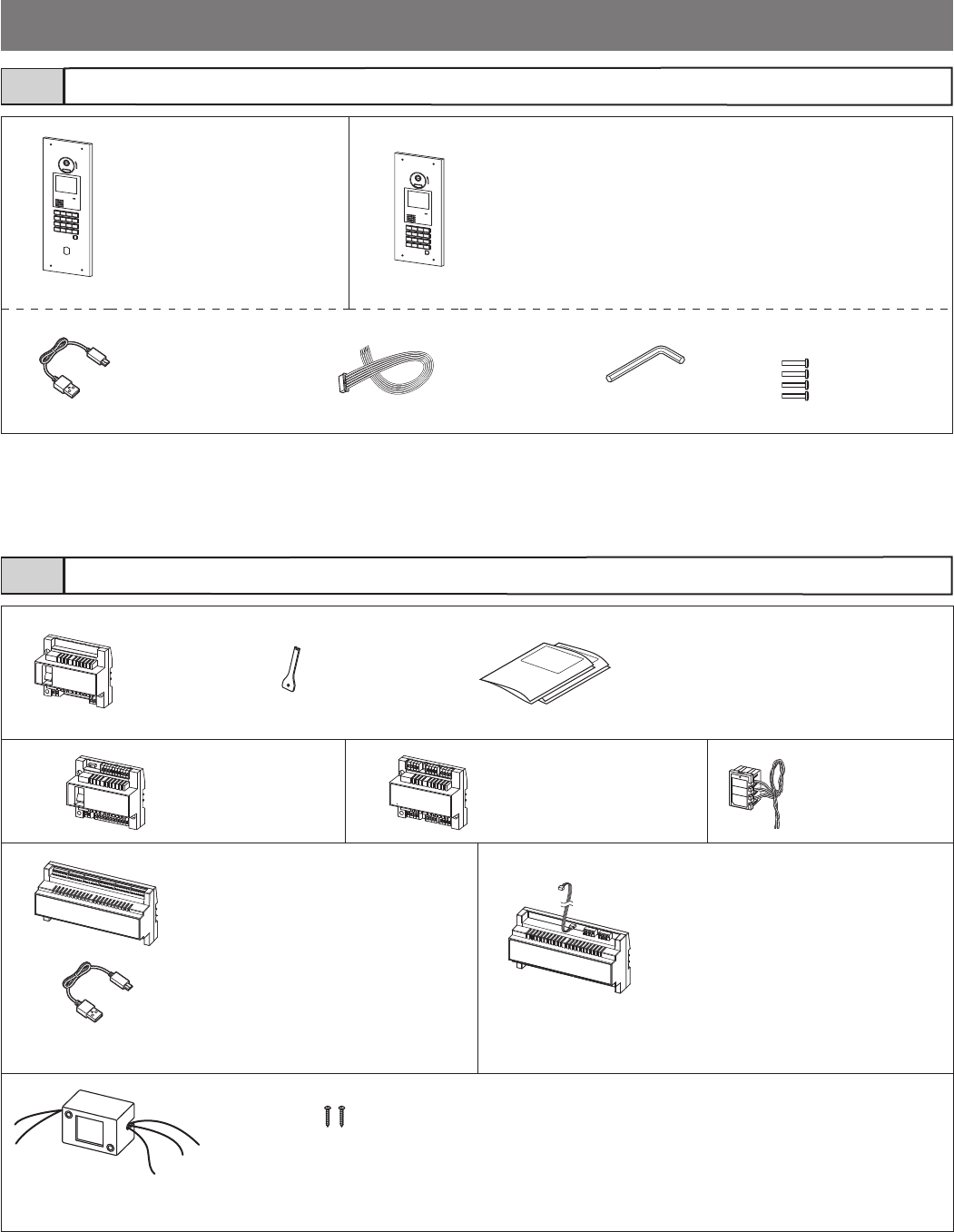
- 14 -
• English, French installation manual (this
manual)
• English, French quick start guide
• Caution sheet (for user)
Bus control unit
GT-BC
Special
screwdriver
USB cable
A-Micro B type (1 m)
* A mounting bracket "DIN rail" included.
Expanded bus control unit
GT-BCXB-N
(NFC capable)
* A mounting bracket "DIN rail" included.
Expanded video bus control unit
GT-VBX
External
signaling relay
GT-RY
Wood mounting
screws
4-way video junction unit
GT-4Z
Video bus control unit
GT-VBC
Video 1-zone divider
GT-1Z
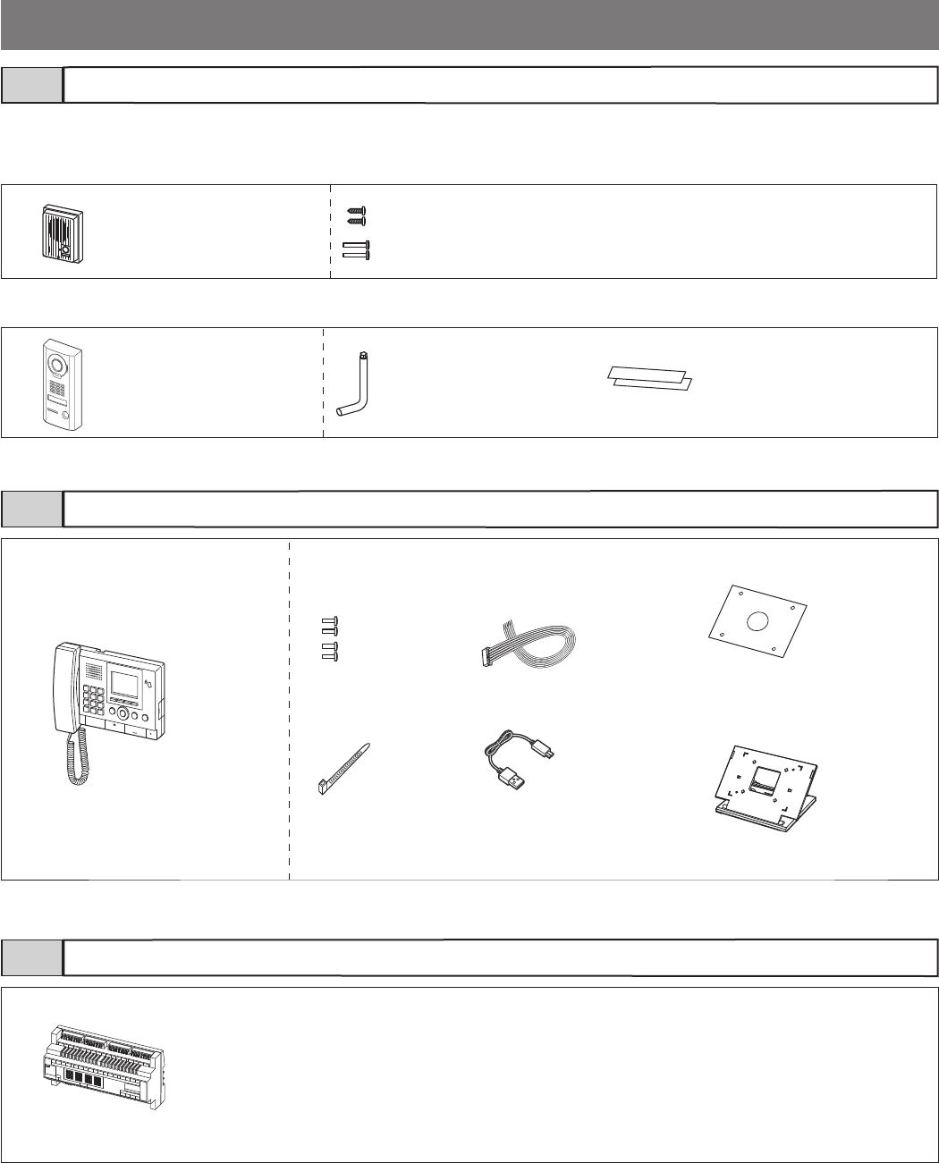
Entrance station (all-in-one type)
Bus control unit etc.
2-2
2-3
All-in-one entrance station
GT-DMB-LVN
(VIGIK and NFC capable)
* GT-4B back box sold separately.
All-in-one entrance station
GT-DMB-N
(NFC capable)
* GF-3B back box sold separately.
USB cable
A-Micro B type (1 m) Screws
Special
screwdriver
Option connector
(7-pin)
* All the above products except GT-DMB-LVN include the Chinese RoHS paper.
* All the above products include the Chinese RoHS paper.
- 15 -
Residential/tenant station, sub residential/tenant station2-4
Residential/tenant station
• GT-2C-L (hearing aid-compatible)
• GT-2C
* A mounting bracket is attached to the product.
Sub residential/tenant station
• GT-2H-L (hearing aid-compatible)
• GT-2H
* A mounting bracket is attached to the product.
Residential/tenant station
(hearing aid-compatible)
GT-1C7-L
* A mounting bracket is
attached to the product.
Residential/tenant
station
GT-1C7
* A mounting bracket is
attached to the product.
Residential/tenant
station (hearing aid-
compatible)
GT-1M3-L
* A mounting bracket is
attached to the product.
Residential/tenant
station
GT-1M3
* A mounting bracket is
attached to the product.
Residential/tenant station
GT-1A
* A mounting bracket is attached to the product.
Wood mounting
screws
Screws
Option connector
• GT-1A: 6-pin
• GT-1D: 8-pin
Residential/tenant station
GT-1D
Optional handset for GT-2C(-L), GT-2H(-L)
GT-HSA
* All the above products include the Chinese RoHS paper.
Wood mounting
screws
Operation manual
Screws
Option connector
(12-pin)
(included with
GT-2C-L, GT-2C)
Option connector
(6-pin)
- 16 -
Guard station
Lift control adaptor
2-5
2-6
2-7
Door station
GT-D
* A mounting bracket is attached to
the product.
Wood mounting screws
Screws
Video door station
JO-DV Special screwdriver
Transparent
nameplate
Guard station
GT-MKB-N
(NFC capable)
* A mounting
bracket is
attached to the
product.
Screws
Cable tie
Option
Connector
(12-pin)
USB cable
A-Micro B
type (1 m)
Insulating
plate
Desk stand
Lift control adaptor
GTW-LC
* A mounting bracket "DIN rail" included.
* All the above products include the Chinese RoHS paper.
* For JK-DA, JK-DV and JK-DVF, refer to the instruction manual included with the product for details.
Door station
[For GT-2C-L, GT-2C]
[For GT-MKB-N]
- 17 -
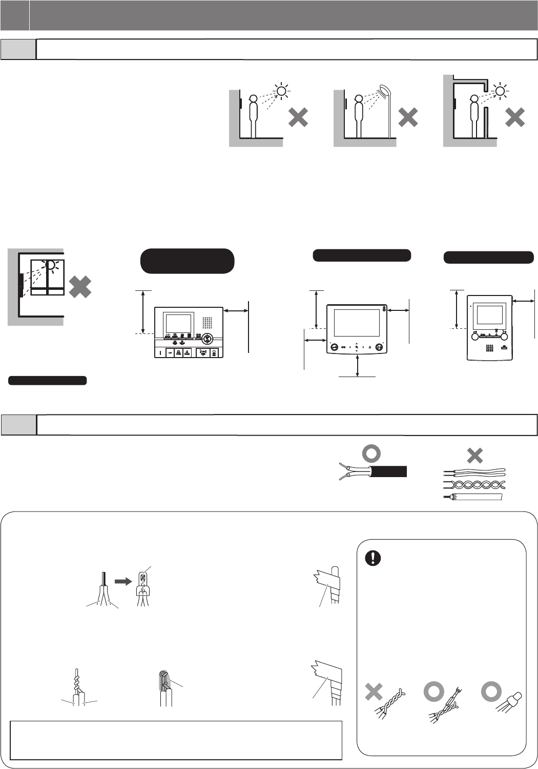
Mounting locations
Cable
3-1
3-2
• For video entrance stations and video door stations, the
picture quality of the residential/tenant station monitor
is affected by the external light surrounding the built-in
camera. Do not install these stations in the types of
locations shown below.
• Locations exposed to direct sunlight
• Locations under street lights or door lights
• Other locations exposed to strong light
• Use PE (polyethylene)-insulated PVC jacket cable.
Parallel or jacketed 2-conductor, mid-capacitance non-shielded cable is
recommended.
• Never use individual conductors, twisted pair cable or coaxial cable.
• Controls are located on the right side of the GT-2C-L/GT-2C, GT-2H-L/GT-2H, GT-1C7-L/GT-1C7 and GT-1M3-L/GT-1M3.
Allow open space of 5 cm (2").
• At least 15 cm (6") of vertical open space from the center of the mounting bracket is needed for mounting the station.
• Entrance stations (all-in-one type) include a sensor. Do not place objects such as plants or trees in places monitored by the sensor.
Also, placing the unit in bright sunlit areas may prevent the sensor from working properly.
15 cm
(6")
5 cm
(2")
(x2
)
15 cm
(6")
5 cm
(2")
GT-1M3-L/GT-1M3
* GT-1C7-L/GT-1C7 only
The station's speaker is on the back. Make sure to leave the specified spaces on all sides to ensure sound clarity.
GT-2C-L/GT-2C
GT-2H-L/GT-2H
15 cm
(6") 5 cm
(2")
5 cm
(2")
5 cm
(2")
GT-1C7-L/GT-1C7 *
3 MOUNTING
To connect low voltage wires, either crimp them with a crimp sleeve or solder them, and then insulate by covering
with insulating tape.
[Crimping with a crimp sleeve]
Solid conductor
Solid
conductor
Keep the number of connections as
low as possible when wiring.
After connecting wires, make sure to check
for breaking or insuffi cient connection.
Especially when connecting a wire in the
middle of wiring, either crimp it with a crimp
sleeve or solder it, and then insulate it by
covering with an insulating tape.
Just twisting wires may cause poor connection,
or the surface of the wires may get oxidized to
cause a loose connection, leading to
malfunctioning or failure.
Stranded conductor
Stranded
conductor
Soldering
Insulating tape
Insulating tape
Crimp sleeve
1. Line up solid and
stranded conductors,
and crimp them.
1. Twist the stranded
conductor around the
solid conductor at least
three times.
2. Bend the tip and solder it.
Make sure no lead wire
sticks out.
3. Overlap more than half of the
width and twist them at least
twice.
[Soldering]
2. Overlap more than
half of the width and
twist them at least
twice.
NOTES:
• If the lead wire with a connector is short, extend it using an interconnecting cable.
• Connectors have polarity, so pay attention and connect properly. If connected incorrectly, the
device won’t work.
Soldering
Crimping with a
crimp sleeve
- 18 -
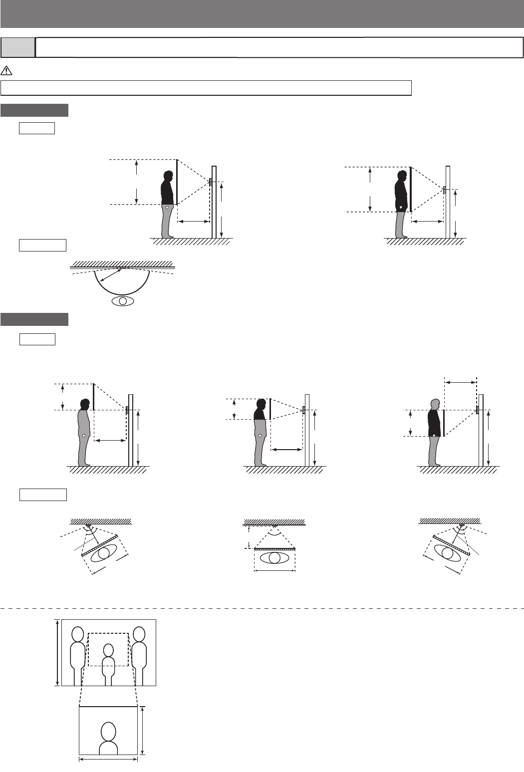
Mounting positions and image view area3-3
When using the camera module, if the rain hood is attached a portion of it will show up in the camera display.
(with mounting position of 1500 mm (5'))
<Left> <Center> <Right>
<Up> <Center> <Down>
Approx. 700 mm (2' 3")
1500 mm (5') 1500 mm (5') 1500 mm (5')
Approx. 550 mm (1' 9")
Approx. 700 mm (2' 3")
Camera
center
Camera
center
Camera
center
Approx. 2200 mm (7' 2")
Approx. 1800 mm (5' 10") Approx. 1500 mm
(5')
Approx. 1500 mm
(5') Approx. 1250 mm
(4' 1") Approx. 800 mm
(2' 8")
Vertical
Vertical
Horizontal
Horizontal
An area over a range of approx. 170° in a 500 mm (20") radius from the camera
displays. (The display range is a rough estimation and may change due to the
installation environment.)
(*1): Zoom view range is approx. 140° at 500mm (20”) distance from the camera.
Mounting position 1500 mm (5')
Approx. 1200 mm (3' 11")
1500 mm (5')
500 mm (20")
500 mm (20")
500 mm
(20")
500 mm (20")
500 mm (20")
500 mm (20")
1300 mm (4' 3")
Approx. 1200 mm (3' 11")
Approx. 170°
Camera center Camera center
Approx. 2100 mm
(6' 11")
Approx. 1900 mm
(6' 3")
Approx. 900 mm
(3') Approx. 700 mm
(2' 3")
Mounting position 1300 mm (4' 3")
Wide view
Zoom view
Objects appear smaller due to greater distortion in the surrounding sections
compared to the central section, but a wider area is displayed.
The display range is a rough estimation and may change due to the installation
environment.
The zoom position can be changed.
The default zoom position is center.
Approx. 900 mm (3')
Approx.
1200 mm
(3' 11")
[Vertical center]
Approx. 550 mm
(1' 9")
Approx.
500 mm
(20")
Approx. 900 mm (3')
Approx. 140° (*1)
Approx.
85°
Approx. 900 mm (3')
Approx.
85°
Approx.
500 mm (20")
Approx.
500 mm
(20")
Approx. 900 mm (3')
Approx. 140° (*1)
Approx.
85°
NOTE: Follow the applicable laws and regulations for mounting location.
- 19 -
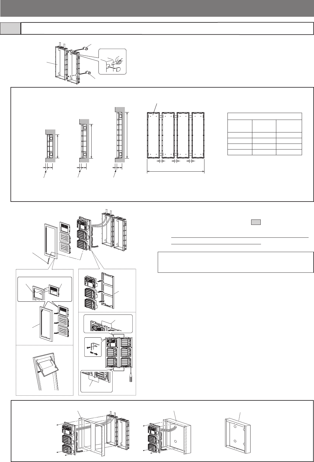
Entrance station (modular type)3-4
1 Make a hole for the cable.
2 Use the joint pipe to assemble the back box.
• Make sure the back box is mounted level.
1
2Joint pipe
Joint pipe
Back box
Options Rain hood GT-203H Surface-mount box GF-203BAHooded surface-mount box GT-203HB
3 Assemble the modules.
• For the useable modules, see section 2-1 .
• The GT-SW can have up to 6 modules.
To connect 7 or more modules or to increase the light intensity,
please contact supplier (need other parts).
4 Mount each module panel to the front frame.
• Mount the panels from behind the front frame.
• Insert the holders into the slots on both sides.
(With the GT-4F, mount the module panels so that they catch on
the tabs from top to bottom.)
5 Mount each module, except the GT-AC, to the mounting
bracket.
• Set the modules in the mounting bracket until they click in place.
• To mount multiple rows of modules, apply the mounting gauge to
the mounting bracket.
While using the mounting gauge to make adjustments, tighten the
screws.
(A mounting gauge is included with the GF-2B, GF-3B, and
GT-4B built-in back boxes.)
54
3
Slot
GT-4F
Mounting
bracket
Mounting gauge
Mounting gauge
Holder
Special
screwdriver
(enclosed with
GT-BC)
Front
frame
Back box assembly dimensions
Back box
GF-2B
25 mm
(1") 25 mm
(1")
25 mm
(1")
W
* 15 mm
(9/16")
44 mm
(1-3/4")
200 mm
(7-7/8")
295 mm
(11-5/8")
400 mm
(15-3/4")
Back box
GF-3B
Back box
GT-4B
NOTE: Before mounting modules to the front panel, complete wiring
and DIP switch settings. (Refer to chapter 4 "Wiring" and
chapter 5 "Settings".)
GF-2B, GF-3B, GT-4B
QTY. W (mm) W (inch)
x 1 110 4-5/16"
x 2 245 9-5/8"
x 3 380 14-15/16"
x 4 515 20-1/4"
* 15 mm
(9/16")
44 mm
(1-3/4")
* 15 mm
(9/16")
44 mm
(1-3/4")
e.g.
Back box GT-4B
* Do not mount the back box on a surface that is recessed by 15 mm (9/16") or more from the external surface of the wall.
- 20 -
8
CN1
CN2
CN1
CN2
CN1
CN1
CN1
CN2
CN1
CN2
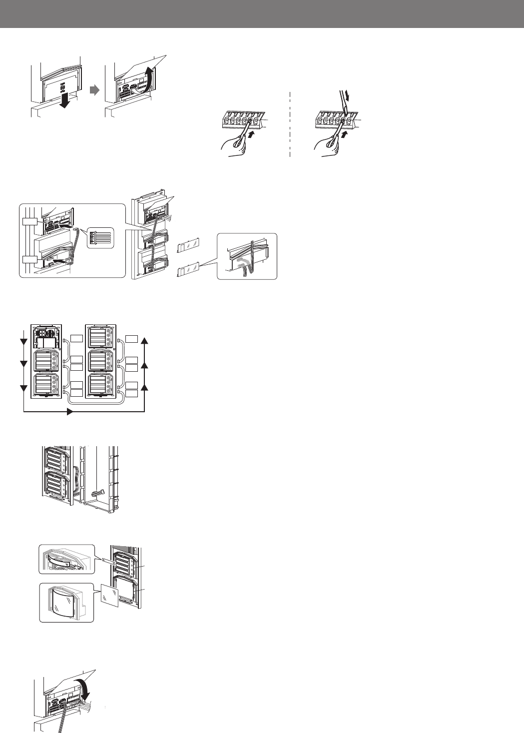
6 Slide down and then open the terminal cover, and connect wires to the
terminal block. Insert the wire into the direct terminal. Press the tab to easily
insert the wire into the terminal, then release.
8 Attach the connection cables between the modules.
Mount modules on the back boxes.
9 Run the connection cable through the joint pipe and connect CN1 of the GT-SW
to the next row.
11 Close the terminal cover.
Mount the front frame and tighten with the special screwdriver (included with
GT-BC).
10 For the GT-SW and GT-AD, remove the resident name/address plate or paper
by pressing either the left or right end. (Peel off the plastic fi lm.)
Use a permanent pen to write the resident name and address on the transparent
plate and mount the plate on the module.
ON
ON
12
ON
7
CN1
CN1
GT-DB(-V, -VN)
GT-SW
7 From the audio module to the next module, insert the attached connector into
the socket.
Make sure to run the cable under the terminal cover for protection.
6GT-DB/GT-DB-V/GT-DB-VN
9
9
11 GT-DB/GT-DB-V/GT-DB-VN
GT-SW
GT-AD
10
GT-SW
GT-AD
- 21 -
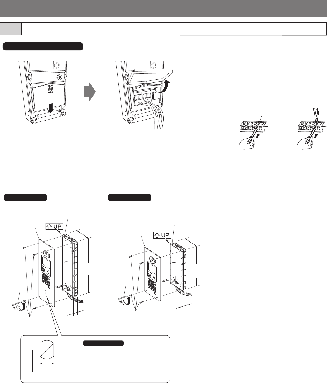
Entrance station (all-in-one type)3-5
1
3
4
3
4
GT-4B (4-module back box)
(not included) GF-3B (3-module back box)
(not included)
Special
screwdriver
Special
screwdriver
Unit
Unit
110 mm
(4-5/16") 110 mm
(4-5/16")
400 mm
(15-3/4") 295 mm
(11-5/8")
44 mm
(1-3/4")
44 mm
(1-3/4")
Mounting screws ×4
(included)
Mounting screws ×4
(included)
1 Slide down and then open the cover,
and connect wires to the terminal
block.
Insert the wire into the direct terminal.
Press the tab to easily insert the wire
into the terminal, then release.
2 Close the cover until it clicks into
place.
3 Mount the unit in the fl ush mount
back box.
4 Tighten the locking screws using the
special screwdriver.
GT-DMB-LVN/GT-DMB-N
GT-DMB-LVN GT-DMB-N
NOTE ( GT-DMB-LVN only ):
For installing VIGIK or a key cylinder, refer
to the instructions included with the product.
18.4 mm (3/4")
Ø25 mm (1")
Release button
- 22 -
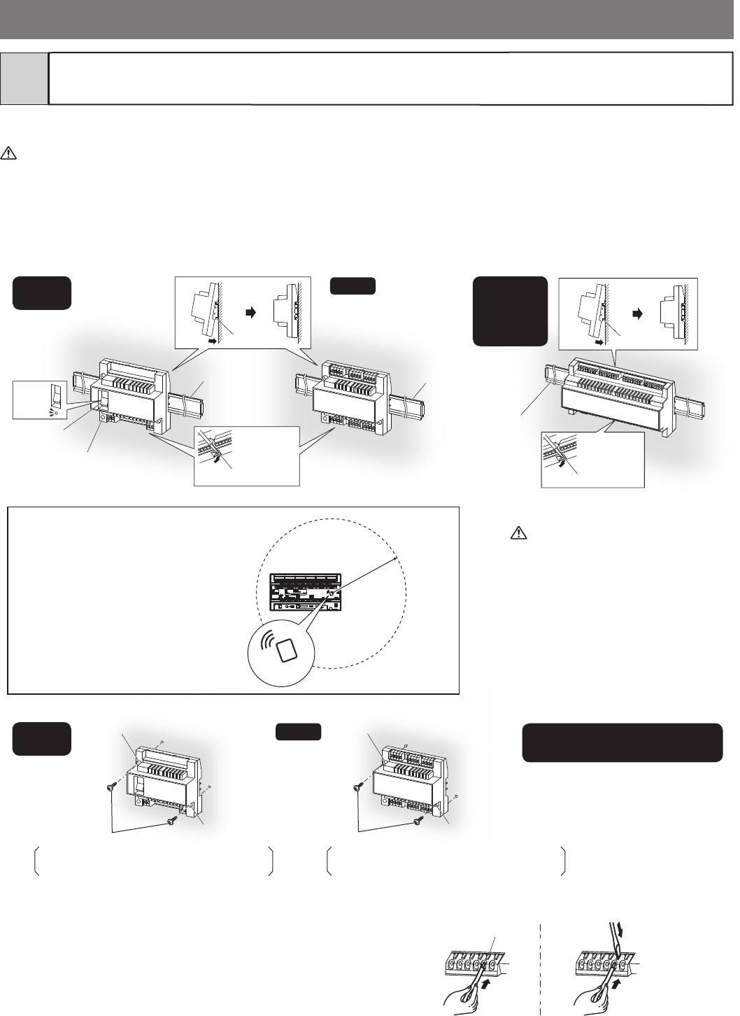
Bus control unit, 4-way video junction unit, lift control adaptor and
power supply
3-6
DIN rail mounting
The maximum cable length between the GT-BCXB-N and GT-VBX is 40 cm. Therefore, mount them side by side.
1 Mount the unit on the DIN rail and then click the unit into place, or mount the unit directly to a wall.
• GT-BC, GT-VBC, and GT-4Z do not include the DIN rail. Use the W-DIN11 for mounting these units.
• GT-BCXB-N, GT-VBX, GT-MCX and GTW-LC are mounted to the included DIN rail.
2 When removing the unit, pull the lock release lever down.
Refer to the installation manual included
with the product.
2
1
2
1
DIN rail DIN rail
DIN rail
(not included)
DIN rail
(not included)
DIN rail
(included)
Power switch
ON
OFF
Power on LED
Lock release lever Lock release lever
Screw hole
Screw hole
Screw hole
Screw hole
GT-4Z
GT-4Z
GT-BC
GT-VBC
GT-BC
GT-VBC
GT-BCXB-N
GT-VBX
GT-MCX
GTW-LC
PS-2420DM, PS-2420, PS-2420S
PS-2420UL, PS-2420BF
Wiring
Insert the wire into the terminal. Press the tab to easily insert the wire
into the terminal, then release.
* The image of the terminals may differ from the
actual product.
• Expanded video bus control unit GT-VBX
Connector cable length: 40 cm
Release button
Mounting screw × 2 (not included)
Screw shaft: Ø4.1 or less
Slotted head: Ø8.2 or less, 3.0mm or less in height
Mounting screw × 2 (not included)
Screw shaft: Ø4.1 or less
Slotted head: Ø8.2 or less, 3.0mm or less in height
NOTES:
• Keep wiring away from NFC mark, as it may
disturb the audio or video signals.
• Be sure to mount the other devices more than
20 cm (7-7/8") away from NFC mark of
GT-BCXB-N.
More than
20 cm
(7-7/8")
NFC mark
GT-BCXB-N
- 23 -
Surface wiring
* The cable can be routed as surface wiring to the top or bottom
of the unit.
Cut a cable inlet on the upper part of the unit to allow passage
of the wiring into the unit from above.
If there is a large amount of wiring, strip away the jacket of the
cable up to the cable inlet.
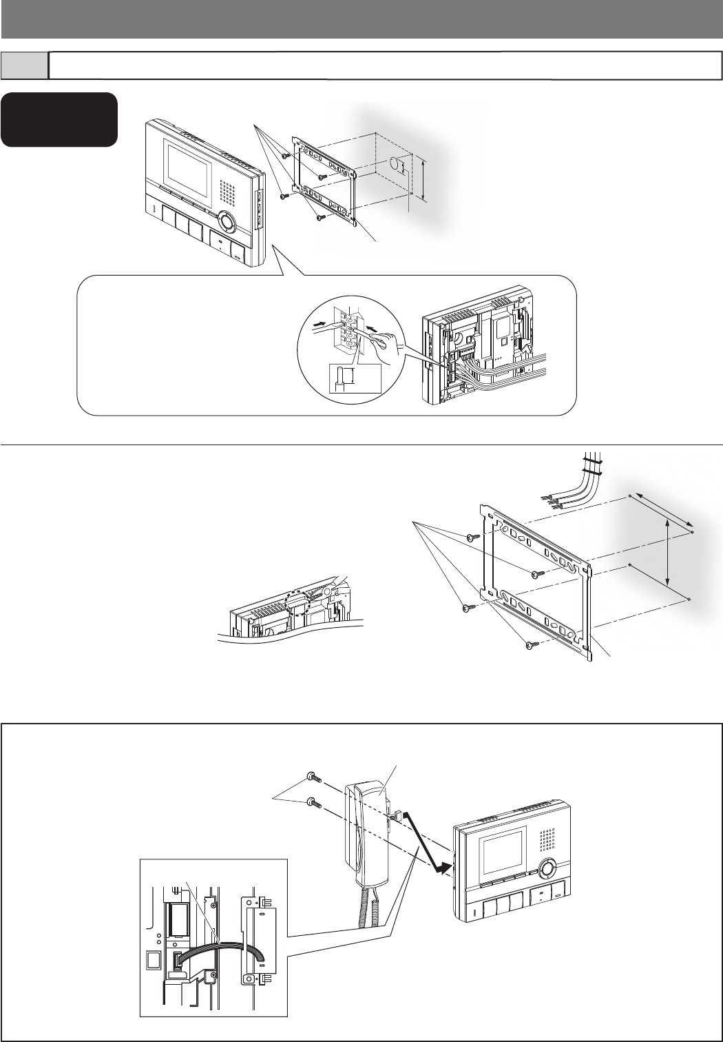
Residential/tenant station3-7
Mounting screws ×4
(included)
Mounting bracket
83.5 mm
(3-5/16")
Optional handset
CN4
Screws × 2 (included)
Handset GT-HSA
Station unit joint connector
Connect the station unit joint
connector.
1. Press the release button
(to insert or remove the wire).
2. Insert the cable into the terminal.
• To remove the terminal block, slide the
terminal block and pull it out.
• Strip away the jacket of the cable and
insert all wires into the slots in an orderly
fashion. Failure to do so could result in
pinching that may damage the wiring.
Mounting screws ×4
(included)
83.5 mm
(3-5/16")
Mounting bracket
12
8 mm
(5/16")
GT-2C-L/GT-2C
GT-2H-L/GT-2H
ø30mm
(1-3/16”)
* When using a gang box, a 3-gang box is
recommended.
92 mm
(3-5/8")
- 24 -
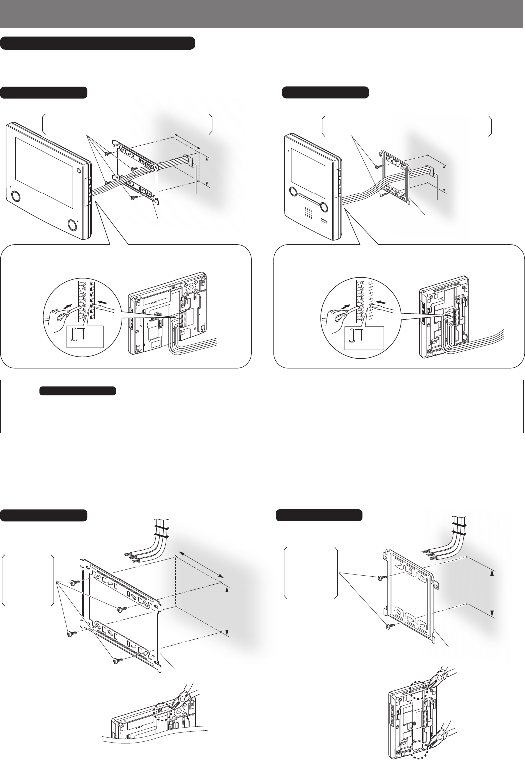
Surface wiring
The wires can be routed to the top or bottom of the station.
Cut the cable inlet to allow passage of the wiring into the station from above.
If there is a large amount of wiring, strip away the jacket of the wire up to the cable inlet.
* To pass the wire through the
back of the station, cut out the
cable inlet.
Mounting bracket
83.5 mm
(3-5/16")
1. Press the release button (to insert or remove the wire).
2. Insert the wire into the terminal.
83.5 mm
(3-5/16”)
92 mm (3-5/8”)
ø30mm
(1-3/16”)
1
2
8 mm
(5/16")
Back wiring
Cut a small round hole (ø30mm (1-3/16”)) in the wall for routing wires.
NOTES ( GT-1C7-L/GT-1C7 only ):
• The station has a speaker on the back. When using a gang box for routing the wires, use a single gang box and attach the mounting bracket to
the wall as shown above. If a 2- or 3-gang box is used, audio quality may be altered.
• Depending on the material of the wall, volume and quality of sound coming from the speaker may be altered.
GT-1C7-L/GT-1C7
GT-1C7-L/GT-1C7
* To pass the wire through
the back of the station, cut
out the cable inlet.
Mounting bracket
83.5 mm
(3-5/16")
83.5 mm
(3-5/16”)
Mounting bracket
Mounting bracket
GT-1M3-L/GT-1M3
GT-1M3-L/GT-1M3
OR
ø30mm (1-3/16”)
Mounting screw × 4 (not included)
Screw shaft: Ø4.1 or less
Slotted head: Ø8.2 or less, 3.0mm or less in height
Mounting screw × 2 (not included)
Screw shaft: Ø4.1 or less
Slotted head: Ø8.2 or less, 3.0mm or less in height
Mounting screw × 4
(not included)
Screw shaft:
Ø4.1 or less
Slotted head:
Ø8.2 or less,
3.0mm or less
in height
GT-1C7-L/GT-1C7, GT-1M3-L/GT-1M3
Mounting screw × 2
(not included)
Screw shaft:
Ø4.1 or less
Slotted head:
Ø8.2 or less,
3.0mm or less
in height
1. Press the release button (to insert or remove the wire).
2. Insert the wire into the terminal.
1
2
8 mm
(5/16")
92 mm (3-5/8”)
- 25 -
1 Mount the mounting bracket on the wall.
* When using a gang box, a single gang box is recommended.
2 Connect wires to the
terminal block.
* If it is diffi cult to insert the
wire, insert it while pressing
the release button.
• To remove the terminal block, slide the terminal block and pull it out.
• Strip away the jacket of the wire and insert all wires into the slots in
an orderly fashion. Failure to do so could result in pinching that may
damage the wiring.
• For surface wiring, cut out the cable inlet.
NOTE: Be sure to route the wires inside the cable guides.
Otherwise, the wires could be damaged when attaching
the station to the mounting bracket.
3 Mount the station to the mounting bracket.
SW1 A B
IN OUT
R1 R2 R1 R2 C
0.65 10 9
CE K KE
Do not remove the wires (For end users)
SW1 AB
IN OUT
R1 R2 R1 R2 C
0.65 10 9
CE K KE
Do not remove the wires (For end users)
SW1 AB
IN OUT
R1 R2 R1 R2
C
CE
K
KE
Do not remove the wires ! (For end users)
0.65~10 9mm
Terminal block
Cable inlet
Cable guide
Mounting screw
(included) Mounting bracket
Mounting screw
83.5 mm (3-5/16")
GT-1A
1
2
3
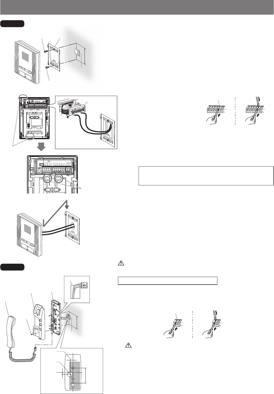
Be careful not to damage the circuit board when connecting wires and
mounting the station. Failure to do so could damage the station.
NOTE : The surface wiring method cannot be used.
1 Remove the screw, and then remove the case from the chassis.
2 Route the wires through the wire inlet of the chassis, and then connect
the wires.
Turn off the GT-BC control unit before connecting wires. Failure to
do so could damage the station.
3 Attach the chassis on the wall.
* Be careful not to pinch the wires between the chassis and the wall.
* When using a gang box, a single gang box is recommended.
4 Attach the case to the chassis and tighten the screw.
5 Plug in the handset to the jack.
* The image of the terminals may differ from the actual product.
Chassis
Inlet
Case
Handset
Screw
83.5 mm (3-5/16")
83.5 mm
(3-5/16")
15 mm
(9/16")
10 mm
(3/8")
GT-1D
Release button
Release button
ø30mm (1-3/16”)
ø30mm (1-3/16”)
ø30mm
(1-3/16”)
- 26 -
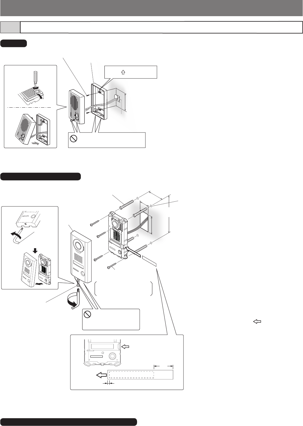
Door station (for residential/tenant station)
3-8
1 Loosen the screws and remove the mounting frame
from the main unit.
2 Mount the mounting frame on the wall.
* When using a gang box, a single gang box is
recommended.
3 After connecting the wiring, mount the main unit to
the mounting frame.
• For surface wiring, insert wiring from the cable inlet
(lower part).
1
2
Mounting frame
Do not block the drainage
holes.
Place " UP" upwards.
83.5 mm (3-5/16")
JK-DA, JK-DV, JK-DVF (for GT-2C-L, GT-2C only)
Refer to the installation manual included with the product.
Mounting screws x 2 (included)
GT-D
1 Loosen the special screw with the
special screwdriver, and remove the
front panel.
2 Insert the transparent nameplate.
1 Peel off the protective seals on the
plate (both sides).
2 Use a permanent pen to write the
resident name on the transparent plate.
* Be sure to leave 25 mm (1") of white
space on the right end to account for
insertion.
3 Insert the fi lled-in transparent
nameplate.
(indicated with in diagram).
3 Connect wires to the unit.
4 Mount the unit to the mounting
surface.
* Use board anchors or concrete plugs as
needed.
5 Replace face plate and tighten special
screw with the included special
screwdriver.
1
2
ABCDEFG
3
4
5
Special
screwdriver
(included)
Special screw
Insert transparent
nameplate here.
Tighten
Loosen
Vandal
resistant
front panel
Drainage hole
Do not block the
drainage holes.
75 mm
(2-15/16")
(The diameter and the depth of the holes on the wall depend
on the anchors suitable for the mounting screws used.)
50 mm
(1-15/16")
150 mm
(5-7/8")
70 mm
(2-3/4'')
2 mm (1/16")
25 mm
(1")
Mounting screw × 4
(not included)
Screw shaft: Ø4.1
Slotted Head: Ø8.2 or less
Height: 3.0mm (1/8") or less
Anchor x 4
(Prepare anchors according to the size of the
mounting screws.) (not included)
JO-DV (for GT-MKB-N only)
ø30mm (1-3/16”)
- 27 -
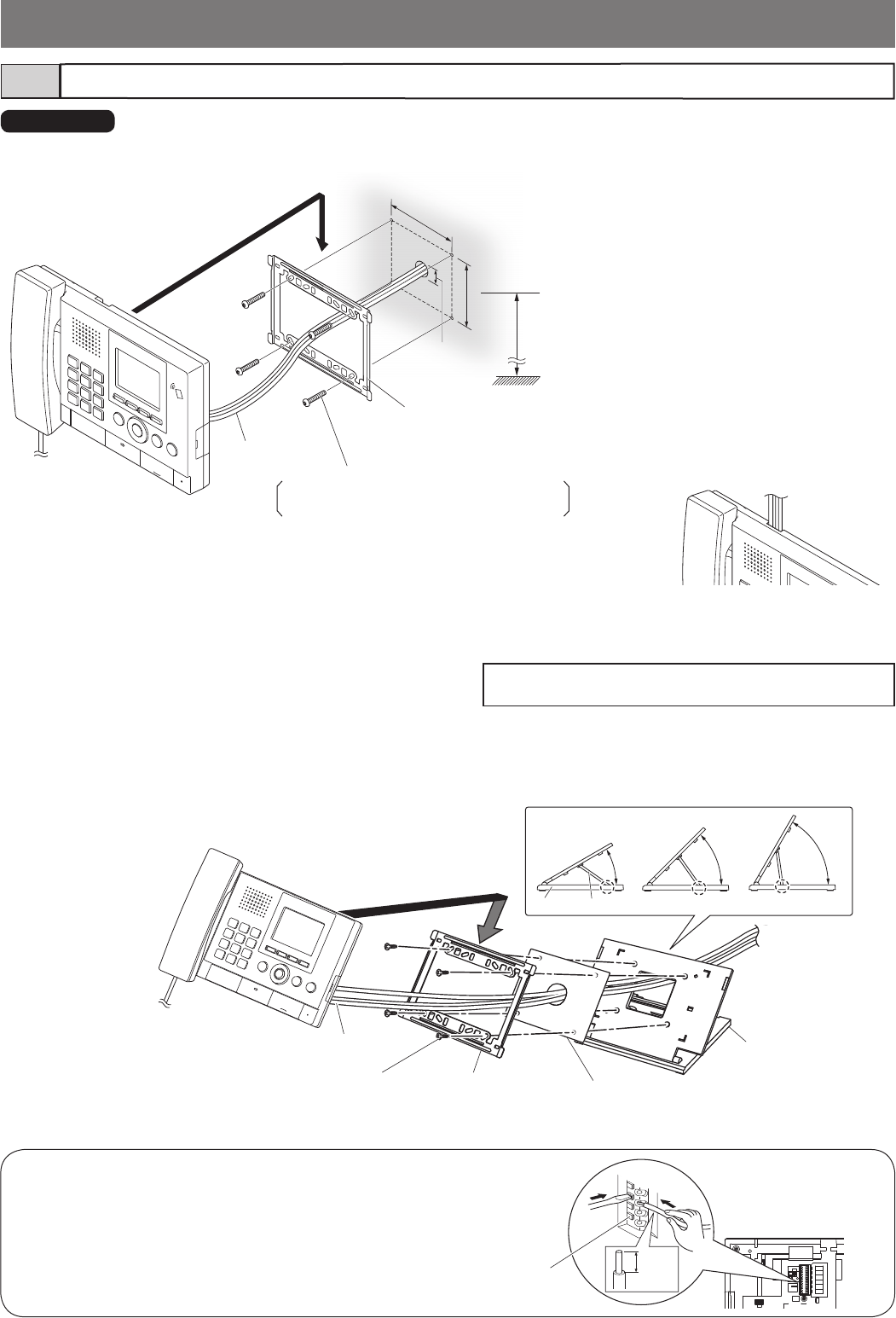
1
2
3
4
30° 45° 60°
1
2
3
When mounting on the desktop stand
Screw (for desktop stand) × 4
(included)
Desktop stand
(included)
Leg
Base
Mounting bracket
(comes attached
to the station)
Insulation plate
(included)
Wires
How to connect and remove wires
1. Press the release button (to insert or remove the wire).
2. Insert the wire into the terminal.
12
Release button
8 mm
(5/16")
Guard station3-9
When mounting on a wall
<Back wiring>
Mounting bracket
(comes attached to the station)
Mounting height
(box center)
1,500 mm (5')
Wires
Connect the wires to the station
and route them as shown in the
fi gure.
GT-MKB-N
Mounting screw × 4 (not included)
Screw shaft: Ø4.1 or less
Slotted head: Ø8.2 or less, 3.0mm or less in height
83.5mm (3-5/16")
92mm (3-5/8")
ø30mm
(1-3/16”)
<Surface wiring>
1 Mount the mounting bracket
to the wall.
* When using a gang box, a
3-gang box is recommended.
2 Connect the wires to the
station.
3 Attach the station to the
mounting bracket.
1 Set up the desktop stand.
* Set up the desktop stand on a level surface so that it is stabilized.
Fix the desktop stand in place if needed.
* The desktop stand can be adjusted to 3 angles.
Fit the leg in a groove on the base for the desired angle.
2 Attach the mounting bracket and insulation plate to the
desktop stand.
3 Connect the wires to the station.
4 Attach the station to
the mounting bracket.
NOTE : Keep wiring away from NFC mark, as it may disturb the
audio or video signals.
- 28 -
DC24V
R1 R2
MODE
EXPAND
STANDARD
R1 R2
R1 R2
R1 R2 R1 R2 R1 R2 R1 R2 R1 R2
R1 R2
1P
NP
1P
NP
1P
NP 1P
NP
1P
NP
1P
NP
1P
NP
1P
NP
1P
NP
1P
NP
1P
NP
1P
NP
1P
NP
1P
NP
1P
NP
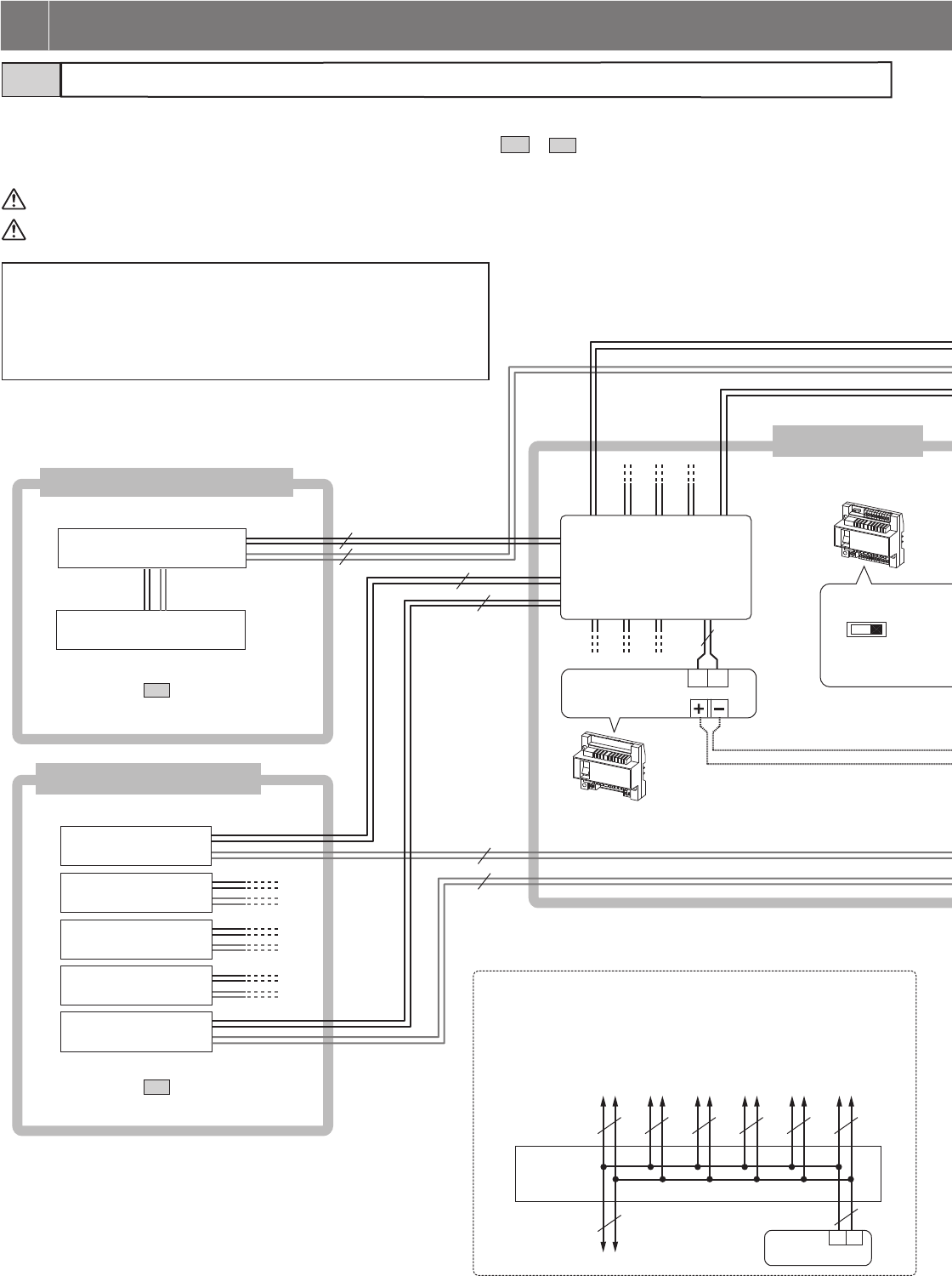
Standard system4-1
Entrance station 1
Entrance station 2
Entrance station 3
Entrance station 4
Entrance station 5
Guard station 2
Guard station 1
Guard station (max. 2)
Entrance station (max. 5)
Video bus control unit
GT-VBC
The following is an example of a basic wiring diagram for the standard system.
* The wiring methods differ depending on the equipment used. Refer to sections 4-2 to 4-4 for the detailed wiring diagrams of entrance
stations, guard stations, and residential/tenant stations.
Each pair of wires should be in a separately jacketed cable (audio, video, and power wiring).
To prevent shorts, unused cables should be insulated.
NOTES:
• Do not use the unused terminals and ports for other purposes.
• In order to prevent miswiring, label both ends of each cable with the unit
and terminal names to which they are to be connected.
• For connecting other manufacturers’ products, refer to the instruction
manuals for those products.
* Refer to section 4-3 for detailed
connection diagrams.
* Refer to section 4-2 for detailed
connection diagrams.
Common area
Bus control unit
GT-BC
DP (Distribution Point)
DP
GT-BC
*1
*1:DP (Distribution Point) wiring example
• When using a distribution terminal block, it is not provided
by Aiphone except for Europe and North America.
• After making connections, be sure to check that there are
no disconnected or loose parts.
4 WIRING
- 29 -
OUT
IN IN IN IN IN
OUT OUT OUT OUT
MAIN DC24V
2
OUT
1
B2
B1 B2
B1 B2
B1 B2
B1 B2
B1 B2
B1
3 4 5 6
1 2 3 4 5
A2
A1 A2
A1 A2
A1 A2
A1 A2
A1
MODE
EXPAND
STANDARD
OUT
IN IN IN IN IN
OUT OUT OUT OUT
MAIN DC24V
2
OUT
1
B2
B1 B2
B1 B2
B1 B2
B1 B2
B1 B2
B1
3 4 5 6
1 2 3 4 5
A2
A1 A2
A1 A2
A1 A2
A1 A2
A1
MODE
EXPAND
STANDARD
OUT
IN IN IN IN IN
OUT OUT OUT OUT
MAIN DC24V
2
OUT
1
B2
B1 B2
B1 B2
B1 B2
B1 B2
B1 B2
B1
3 4 5 6
1 2 3 4 5
A2
A1 A2
A1 A2
A1 A2
A1 A2
A1
MODE
EXPAND
STANDARD
OUT
IN IN IN IN IN
OUT OUT OUT OUT
MAIN DC24V
2
OUT
1
B2
B1 B2
B1 B2
B1 B2
B1 B2
B1 B2
B1
3 4 5 6
1 2 3 4 5
A2
A1 A2
A1 A2
A1 A2
A1 A2
A1
PS24
PS24
AC
PS24
AC
PS24
AC
AC
1P
NP
1P
NP
1P
NP
1P
NP
1P
NP
1P
NP
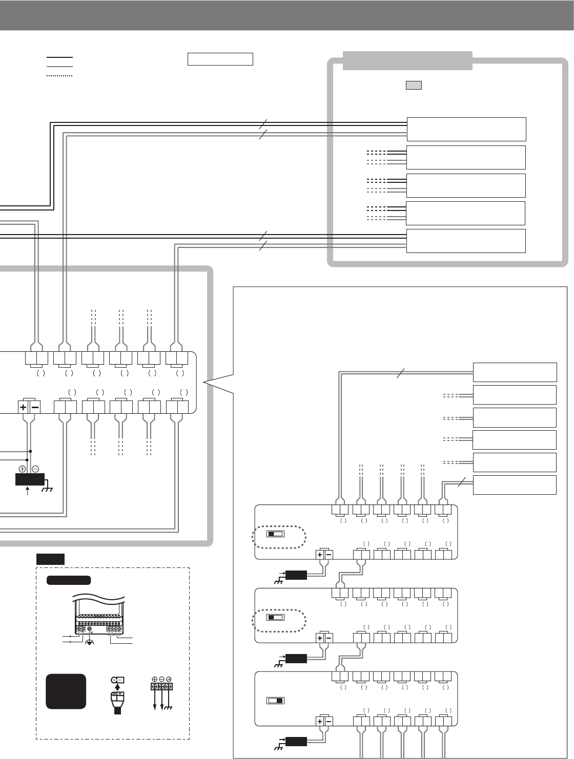
Residential/tenant trunk
Up to two GT-VBC can be used as extension adaptors per trunk line.
(Please note that images and terminal position in this manual may differ from the actual product.)
To use the GT-VBC as an extension adaptor, set the MODE setting switch to
[EXPAND].
The wires must be connected to the IN (1) terminals.
Residential/tenant
trunk 1
Residential/tenant
trunk 2
Residential/tenant
trunk 3
Residential/tenant
trunk 4
Residential/tenant
trunk 5
Residential/tenant
trunk 6
* Refer to section 4-4 for detailed connection diagrams.
PS24
230 V AC 50/60 Hz 24 V DC2A
N
L
-
+
100V - 240V -
50/60 Hz
24V DC
2 A
PS-2420DM
PS-2420
PS-2420S
PS-2420UL
PS-2420BF
Residential/tenant trunk 1
Residential/tenant trunk 2
Residential/tenant trunk 3
Residential/tenant trunk 4
Residential/tenant trunk 5
NP: Non-polarized
: Audio signal line
: Video signal line
: Power supply line
*3
*2
*2
*3
*2:
*3:
- 30 -
Guard station4-2
V+
V
RYK
RYK
RYV
RYV
RYC
RYC
CE
C
SW
SW
OUT INOUT
DOOR
IN
DC24V
OUT INOUT
DOOR
IN
DC24V
B1
A
B
B2
B1
B2
R1
R2
R1
R2
A1
A2
USB
+
-
CN1
SW2
ON
SW1
1 2 3 4
B1
A
B
B2
B1
B2
R1
R2
R1
R2
A1
A2
USB
+
-
CN1
SW2
ON
SW1
1 2 3 4
A1
A2
V+
V
RYK
RYK
RYV
RYV
RYC
RYC
CE
C
SW
SW
ACAC
1P
NP
1P
NP
1P
NP
1P
NP
1P
NP
NP
NP
NP
NP
NP
P
GT-VBC GT-BC
DP
AC
PS24
* Connect to the bus control units.
Standard system: section 4-1
Expanded system: section 4-5
Guard station 1
GT-MKB-N
Guard station 2
GT-MKB-N
External
signal
relay
GT-RY
External
signal
relay
GT-RY
External
signal
relay
GT-RY
Doorbell
Video door station
JO-DV
PC
(third party product)
Monitor/DVR
(third party product)
Video
output
contact
Buzzer
etc.
Buzzer
etc.
Brown
Red
Red
Orange
Blue
Gray
Yellow
Red
Black
Green
Purple
White
Option
button
output
: Audio signal line
: Video signal line
: Power supply line
Termination setting:
For terminating guard station,
set SW1 to "A".
NOTES:
• Refer to section 4-7 for option connector details.
• Refer to section 5-1 for the switch settings.
(Please note that images and terminal position in this manual may differ from the actual product.)
Set SW1 to "B".
P: Polarized
NP: Non-polarized
- 31 -
A2
A1
CN1
5P
ON
SW1
1 2 3 4
PT
PT
6P
V
V
CN100
CN100
CN11
CN1
CN1
CN2
CN3 CN4
CN1
CN2
CN3 CN4
CN1
CN2
CN3 CN4
ELM
ELC
ELB
BP
BP
R2
R1
USB
CN2
CN3
CN2
CN1
ON
SW3
SW2
1234
ON
1 2 3 45 6 7 8
D
D
GND
RY
RY
SP
SP
5P
5P 5P
6P
6P
5P
6P
9P
9P
2
B
A
C
3
E
D
F
5
K
J
L
8
U
T
V
4
H
G
I
6
N
M
O
1
0
9
Y
X
W
Z
7
R
Q
P
S
AC
GT-VB
GT-SW/GT-AD
GT-NSB
GT-DB GT-10K
GT-VB GT-NSB
GT-DB GT-SW
GT-VBC
GT-BC
DP
NP
1P
NP
1P
NP
P
AC
PS24
AC
NP
PC
(third party product)
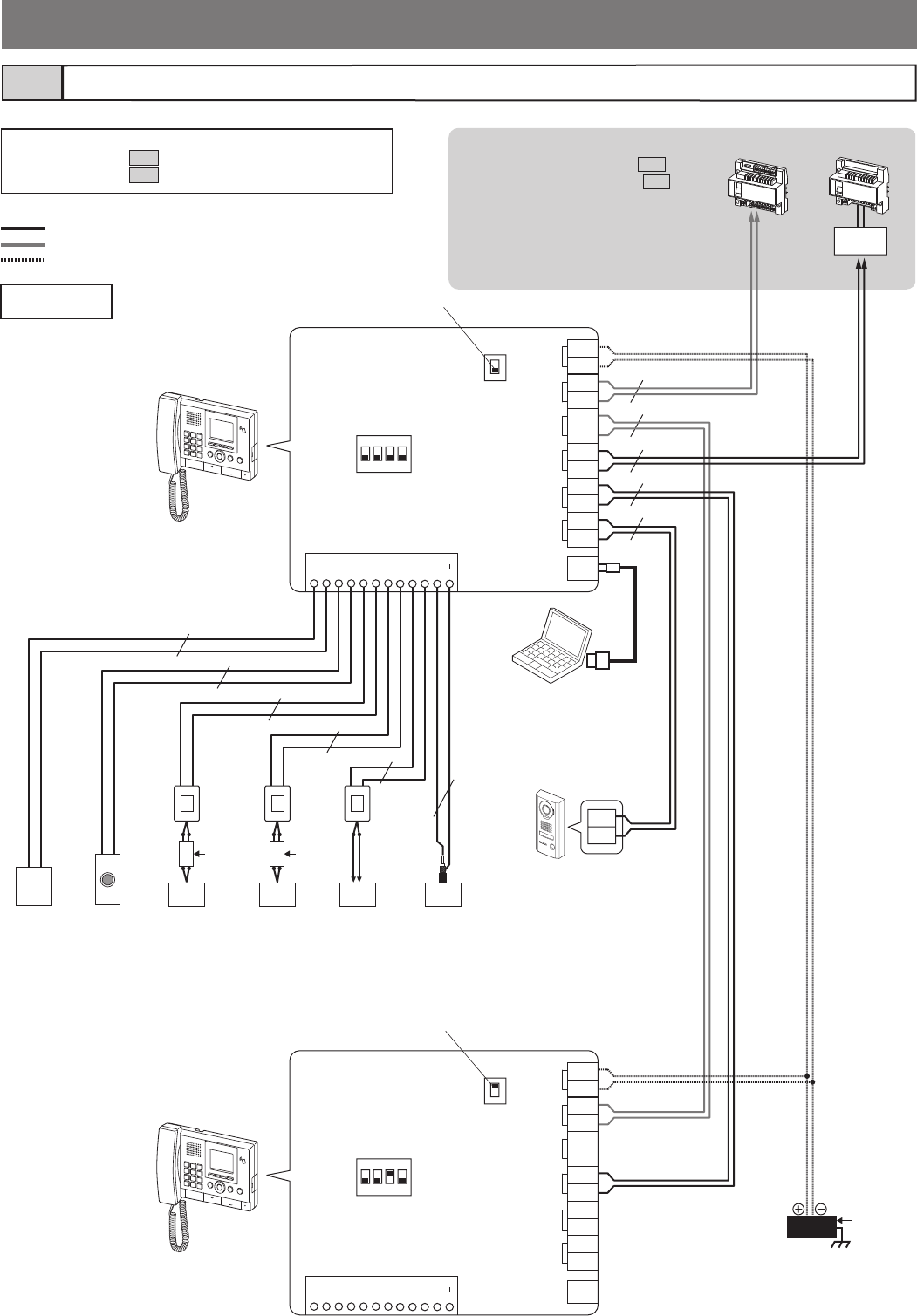
Entrance station4-3
Modular type and all-in-one type entrance stations are available.
The wiring method differs depending on the type or the combination
of modular units, as shown below.
■ Modular type (video and audio)
Surveillance camera
(third party product,
NTSC 75 )
External door
release button
(third party
product) (*3)
Door release
(third party product) (*1)
Modular unit combination example
Camera module
GT-VB
OR
10-key module
(10 keys)
GT-10K
GT-SW/GT-AD
(one unit only)
Call switch module GT-SW/
Address module GT-AD
Name scroll module GT-NSB
Another entrance station
Another entrance station
Brown
Red
P: Polarized
NP: Non-polarized
: Audio signal line
: Video signal line
: Power supply line
* Connect to the
bus control
units.
Standard
system:
section 4-1
Expanded
system:
section 4-5
NOTES:
• Refer to section 4-7 for option connector details.
• Refer to section 5-1 for the switch settings.
(*2)
(*1): N/C (Normally Closed) [ELB, ELC]
N/O (Normally Open) [ELM, ELC]
Less than AC/DC 24V, 4A (resistive load)
(*2): GT-DB-V and GT-DB-VN only.
(*3): Input specifi cations
Input method N/O (Normally Open)
contact
Detection confi rmation time 100 ms or more
Closed contact resistance 1 k or less
Open contact resistance 50 k or more
Terminal short current 10 mA or less
Open circuit voltage between terminals 3.3 V DC or less
Audio module
GT-DB(-V, -VN)
(Please note that images and terminal position in
this manual may differ from the actual product.)
Magnetic loop
module
Green
Purple
Yellow
Blue
Red
Orange
Brown
External
signal relay GT-RY
GT-DB-V, GT-DB-VN only
VIGIK
- 32 -
■ Modular type (audio only)
5P
6P
CN100
CN100
CN11
CN1
CN1
CN2
CN3 CN4
CN1
CN2
CN3 CN4
CN1
CN2
CN3 CN4
ELM
ELC
ELB
BP
BP
R2
R1
USB
CN2
CN3
CN1
ON
SW3
SW2
1234
ON
1 2 3 45 6 7 8
D
D
GND
RY
RY
SP
SP
5P
6P
6P
5P
6P
9P
9P
PT
PT
2
B
A
C
3
E
D
F
5
K
J
L
8
U
T
V
4
H
G
I
6
N
M
O
1
0
9
Y
X
W
Z
7
R
Q
P
S
AC
GT-SW/GT-AD
GT-SW/GT-AD
GT-BC
DP
NP
NP
1P
NP
NP
GT-NSB
GT-DB
GT-SW
GT-SW
GT-DB
GT-SW
GT-NSB
GT-DB
GT-10K
AC
AC
PS24
Modular unit combination example
Audio module GT-DB(-V, -VN)
Magnetic loop
module
OR
10-key module
(10 keys)
GT-10K
Call switch module GT-SW/
Address module GT-AD
Name scroll module GT-NSB
Another entrance station
Another entrance station
Green
Purple
Yellow
Blue
Red
Orange
Brown
External
signal
relay
VIGIK
NP: Non-polarized
: Audio signal line
: Video signal line
: Power supply line
* Connect to the
bus control units.
Standard
system:
section 4-1
Expanded
system:
section 4-5
External door release button
(third party product) (*3)
Door release
(third party product) (*1)
(*2)
(*1): N/C (Normally Closed) [ELB, ELC]
N/O (Normally Open) [ELM, ELC]
Less than AC/DC 24V, 4A (resistive load)
(*2): GT-DB-V and GT-DB-VN only.
PC
(third party product)
NOTE: Refer to section 5-1 for the switch settings.
GT-RY
(*3): Input specifi cations
Input method N/O (Normally Open)
contact
Detection confi rmation time 100 ms or more
Closed contact resistance 1 k or less
Open contact resistance 50 k or more
Terminal short current 10 mA or less
Open circuit voltage between terminals 3.3 V DC or less
(Please note that images and terminal position in this manual may differ from the actual product.)
GT-DB-V, GT-DB-VN only
- 33 -
ELM ELC ELB
A2 BPBPA1 R2R1
USB
CN1 SW1
ON
1 2 3 45 6 7 8
DC24V
D
D
GND
V
V
RY
RY
PS24
AC
PT
PT
P
NP
NP
AC
1P
NP
NP
1P
NP
GT-VBC
GT-BC
DP
AC
External
signal
relay
VIGIK
■ All-in-one type
* Connect to the bus
control units.
Standard system:
section 4-1
Expanded system:
section 4-5
Surveillance
camera
All-in-one entrance station
GT-DMB-LVN/GT-DMB-N
Another entrance station
Another entrance station
Green
Purple
Ye l l o w
Blue
Red
Orange
Brown
NP: Non-polarized
P: Polarized
: Audio signal line
: Video signal line
: Power supply line
External door
release button
(third party product) (*2)
Door release
(third party product) (*1)
(*1): N/C (Normally Closed) [ELB, ELC]
N/O (Normally Open) [ELM, ELC]
Less than AC/DC 24V, 4A (resistive load)
PC
(third party product)
NOTE: Refer to section 5-1 for the switch settings.
GT-RY
(*2): Input specifi cations
Input method N/O (Normally Open)
contact
Detection confi rmation time 100 ms or more
Closed contact resistance 1 k or less
Open contact resistance 50 k or more
Terminal short current 10 mA or less
Open circuit voltage between terminals 3.3 V DC or less
(Please note that images and terminal position in this manual may differ from the actual product.)
GT-DMB-LVN only
- 34 -
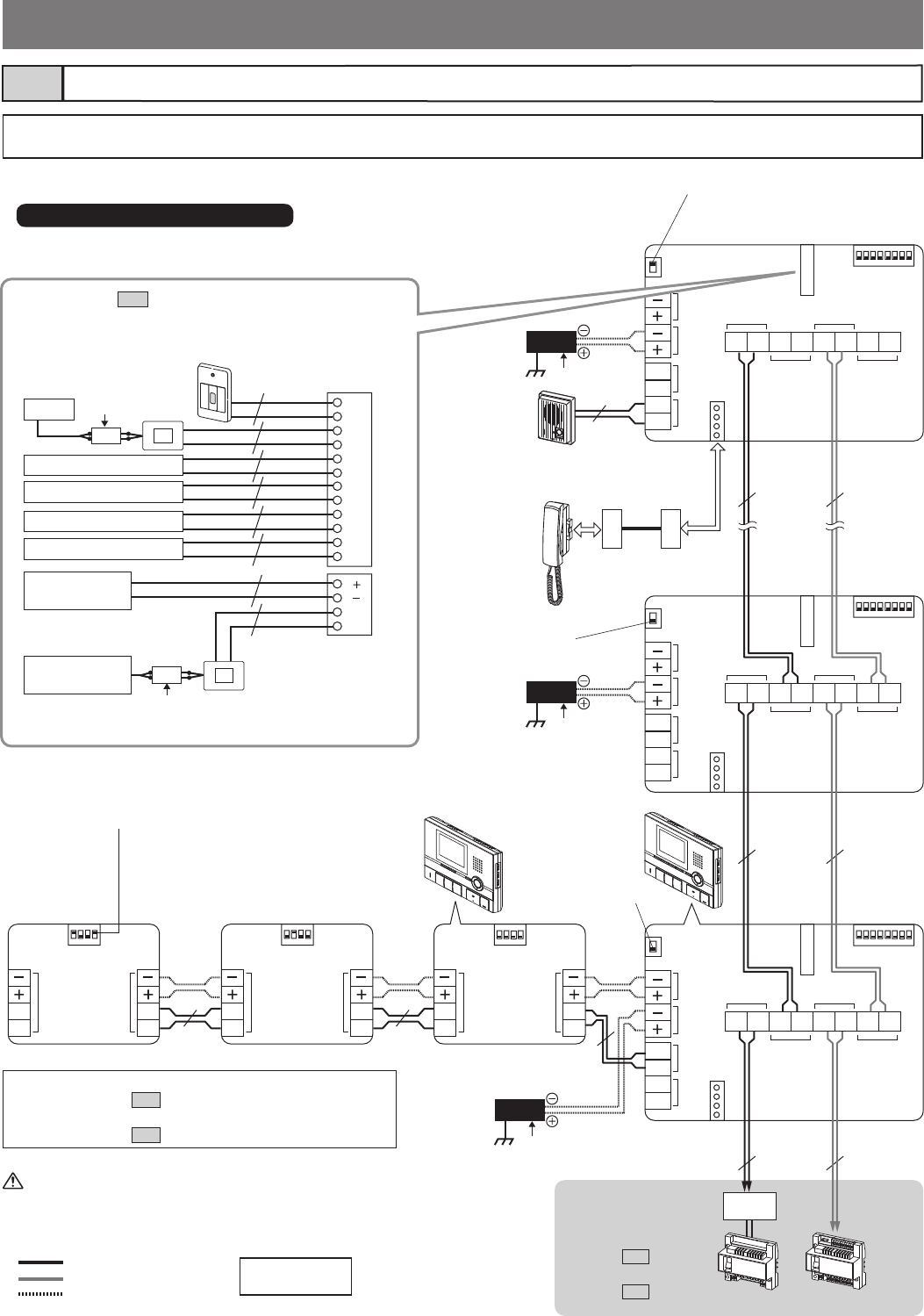
Residential/tenant trunk4-4
NOTE: This system allows 3 types of connection methods: "Loop wiring method", "GT-4Z wiring method", and "GT-1Z wiring method".
Select the method suitable for the application and usage of the system.
■ Loop wiring method
SUB
DOOR
H2
H1
A2
A1
SW2
ON
1 2 3 45 6 7 8
A
BSW1
CN4
OPTION
IN
B1 B2 B1 B2
OUT
IN
OUT
R1 R2 R1 R2
OUTIN SUB
DOOR
H2
H1
A2
A1
SW2
ON
1 2 3 45 6 7 8
A
BSW1
CN4
OPTION
IN
B1 B2 B1 B2
OUT
IN
OUT
R1 R2 R1 R2
OUTIN SUB
DOOR
H2
H1
A2
A1
SW2
ON
1 2 3 45 6 7 8
A
BSW1
CN4
OPTION
IN
B1 B2 B1 B2
OUT
IN
OUT
R1 R2 R1 R2
OUTIN
SW2
ON
1 2 3 4
H1
H2
H1
H2
OUT
IN
SW2
ON
1 2 3 4
H1
H2
H1
H2
OUT
IN
SW2
ON
1 2 3 4
H1
H2
H1
H2
OUT
IN
4P4P
GT-VBC
GT-BC
DP
NP
NP
NP
NP
NP
NP
P
NP
AC
AC
1P
NP
1P
NP
1P
NP
1P
NP
1P
NP
1P
NP
1P
NP
PS24
RY
RY
SW
KE
K
SW
V
V
S2E
S2
S3
S1E
S1
S3E
OPTION
CN1
CN2
AC
PS24
AC
PS24
AC
1P
NP
1P
NP
1P
NP
Residential/tenant
station
GT-2C-L/GT-2C
Sub residential/
tenant station
GT-2H-L/GT-2H
GT-2C-L/GT-2C
GT-2H-L/GT-2H GT-2H-L/GT-2H
GT-2C-L/GT-2C
Emergency
alarm switch
Sensor, button, etc.
Option contact output
Buzzer etc.
Sensor, button, etc.
Sensor, button, etc.
External video
device
External video
device
External
signal
relay
Door station
JK-DA
JK-DV
JK-DVF
GT-D
Handset
GT-HSA
Termination setting:
For terminating a residential/tenant
station, set SW1 to "A".
Termination setting:
For terminating sub residential/tenant
station, turn 4 on SW2 to ON.
GT-2C-L/GT-2C, GT-2H-L/GT-2H
* Connect to the bus
control units.
Standard system:
section 4-1
Expanded system:
section 4-5
: Audio signal line
: Video signal line
: Power supply line
* Refer to section 4-7 for details about the option connector.
After connecting a residential/tenant station and a door
station (or doorbell), power cycle the unit.
Brown
Red
Gray
White
Black
Blue
Orange
Black
Purple
Black
Black
Yellow
Brown
Red
Yellow
Orange
NOTES:
• Refer to section 4-7 for details about wiring to the
option connector.
• Refer to section 5-2 for the switch settings.
GT-RY
GT-RY
(Please note that images and terminal position in this manual may differ from the actual product.)
Set SW1 to "B".
Set SW1 to "B".
NP: Non-polarized
P: Polarized
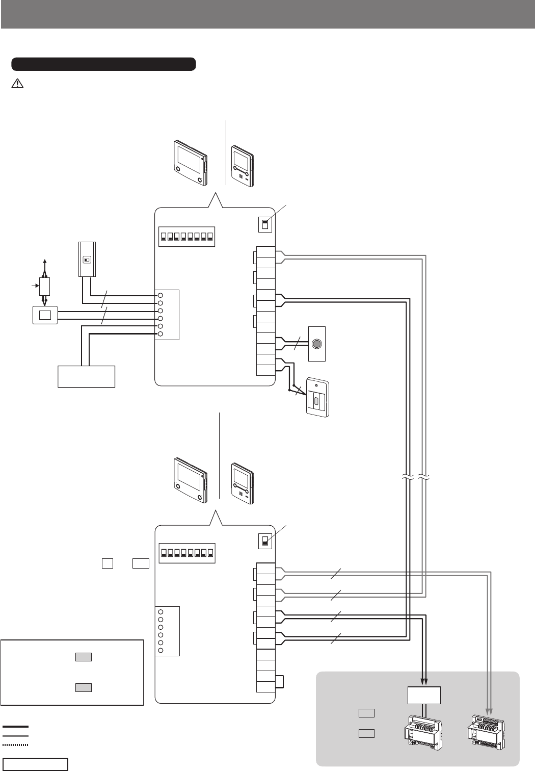
- 35 -
RYC
RYC
SW
DC
DC
SW
OUTOUT IN IN
RYC
RYC
SW
DC
DC
SW
OUTOUT IN IN
B1
B2
B1
B2
R1
R2
R1
R2
C
CE
K
KE
OPTION
SW2
ON
12345 6 7 8
A
B
SW1
B1
B2
B1
B2
R1
R2
R1
R2
C
CE
K
KE
OPTION
SW2
ON
1 2 3 45 6 7 8
A
B
SW1
NP
NP
NP
NP
1P
NP
1P
NP
1P
NP
1P
NP
GT-VBC
GT-BC
DP
AC
Residential/tenant station
GT-1M3-L/GT-1M3
Residential/
tenant station
GT-1M3-L/
GT-1M3
Residential/tenant station
GT-1C7-L/GT-1C7
Residential/
tenant station
GT-1C7-L/
GT-1C7
Doctor call
Option button
output
Termination setting:
For terminating a residential/tenant
station, set SW1 to "A".
Set SW1 to "B".
Emergency alarm
switch (*2)
(GFK-PS available
in N. America only)
Doorbell (*1)
(third party
product)
(*3)
Yellow
Orange
Gray
Blue
Black
White
Turn off the GT-BC control unit before connecting wires. Failure to do so could damage the station.
GT-1C7-L/GT-1C7, GT-1M3-L/GT-1M3
NP: Non-polarized
: Audio signal line
: Video signal line
: Power supply line
* Connect to the bus
control units.
Standard system:
section 4-1
Expanded system:
section 4-5
■ Loop wiring method
NOTES:
• Refer to section 4-7 for details
about wiring to the option
connector.
• Refer to section 5-2 for the ID
switch settings.
Option contact
output
(*1): Doorbell
• N/O contact (non-locked type)
• DC 12 V/0.1 A or higher
(*2): Emergency alarm switch
• N/C contact (locked type)
• DC 12 V/0.1 A or higher
(*3): Jumper wire between K and KE .
Jumper wire must remain in place
if not using an emergency alarm
switch.
GT-RY
(Please note that images and terminal position in this manual may differ from the actual product.)
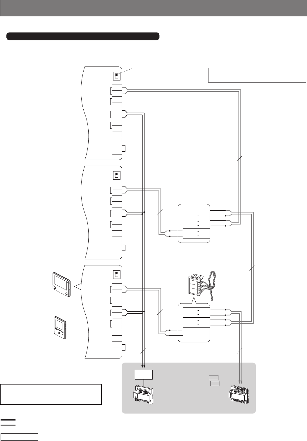
- 36 -
OUTOUT IN INOUTOUT IN INOUTOUT IN IN
B1
B2
B1
B2
R1
R2
R1
R2
C
CE
K
KE
A
B
SW1
B1
B2
B1
B2
R1
R2
R1
R2
C
CE
K
KE
A
B
SW1
B1
B2
B1
B2
R1
R2
R1
R2
C
CE
K
KE
A
B
SW1
YEL B1
WHT
B2
LINE
IN
YEL B1
WHT
B2
LINE
OUT
BLU B1
WHT
B2 OUT
YEL B1
WHT
B2
LINE
IN
YEL B1
WHT
B2
LINE
OUT
BLU B1
WHT
B2 OUT
GT-1C7-L/GT-1C7
GT-1C7-L/GT-1C7
GT-1Z
1P
NP
1P
NP
1P
NP
1P
NP
1P
NP
1P
NP
GT-VBC
GT-BC
DP
GT-1M3-L/GT-1M3
GT-1M3-L/GT-1M3
■ GT-1Z wiring method (using the video 1-zone divider)
* The following diagram is a wiring example using the residential/tenant stations GT-1C7-L/GT-1C7 and GT-1M3-L/GT-1M3.
Video 1-zone divider
GT-1Z
Blue
White
Yellow
Yellow
White
White
Blue
White
Yellow
Yellow
White
White
Residential/tenant station
GT-1M3-L/GT-1M3
Residential/tenant station
GT-1C7-L/GT-1C7
* Connect to the bus control units.
Standard system: section 4-1
Expanded system: section 4-5
NP: Non-polarized
: Audio signal line
: Video signal line
Termination setting:
For terminating a residential/tenant
station, set SW1 to "A".
GT-2C-L/GT-2C, GT-1C7-L/GT-1C7, GT-1M3-L/GT-1M3
NOTE: Refer to pages 34 and 35 for the
wiring details of residential/tenant
stations.
NOTE: Do not connect the GT-1Z to the
terminal residential/tenant station.
(Please note that images and terminal position in this manual may differ from the actual product.)
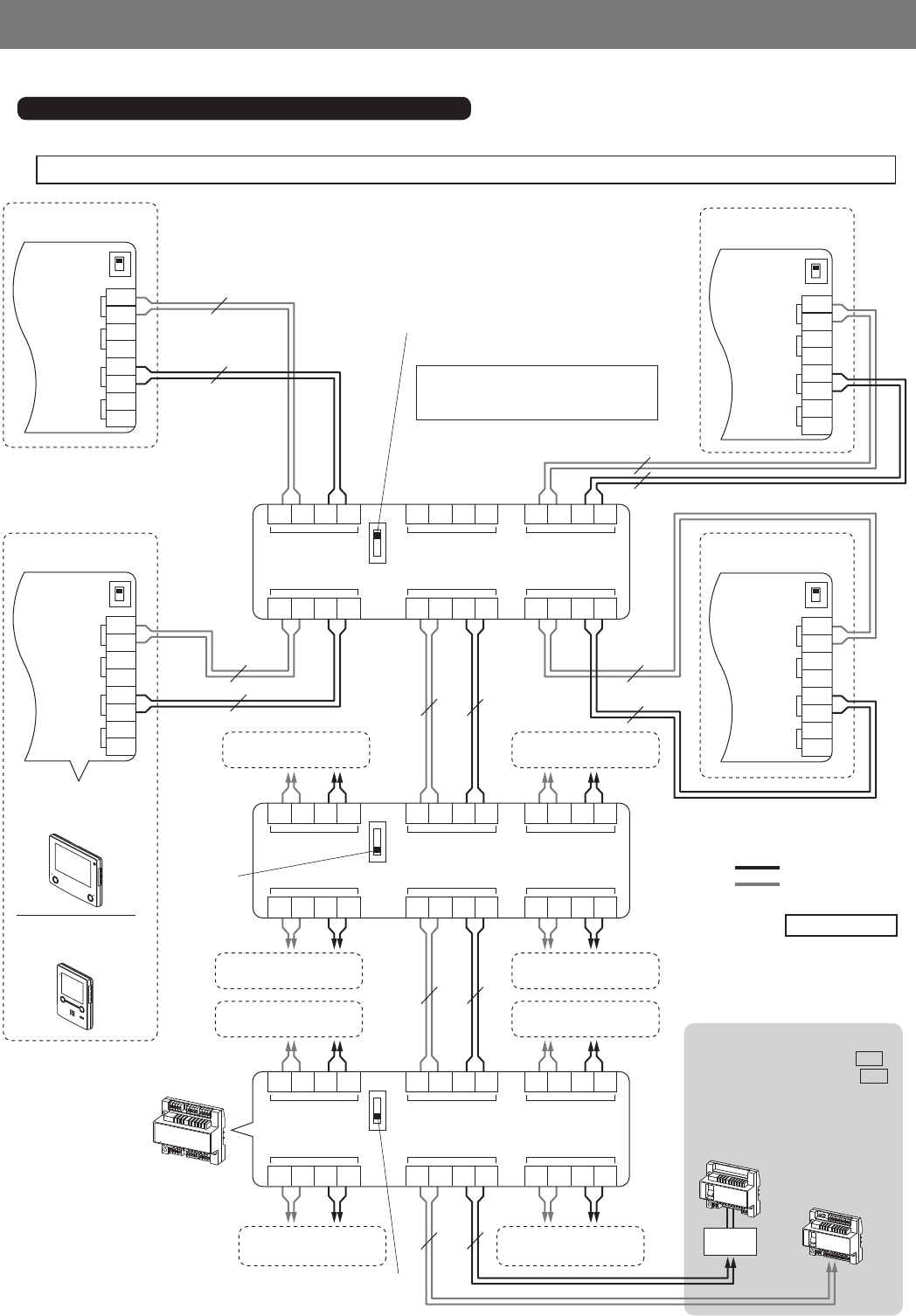
- 37 -
■ GT-4Z wiring method (using the 4-way video junction unit)
* The following diagram is a wiring example using the residential/tenant stations GT-1C7-L/GT-1C7 and GT-1M3-L/GT-1M3.
B
A
SW1
OUT(2)
OUT(4)
B1 B2 R1 R2
B1 B2 R1 R2
IN
LINE OUT
B1 B2 R1 R2
B1 B2 R1 R2
OUT(1)
OUT(3)
B1 B2 R1 R2
B1 B2 R1 R2
SW1
OUT(2)
OUT(4)
B1 B2 R1 R2
B1 B2 R1 R2
IN
LINE OUT
B1 B2 R1 R2
B1 B2 R1 R2
OUT(1)
OUT(3)
B1 B2 R1 R2
B1 B2 R1 R2
SW1
OUT(2)
OUT(4)
B1 B2 R1 R2
B1 B2 R1 R2
IN
LINE OUT
B1 B2 R1 R2
B1 B2 R1 R2
OUT(1)
OUT(3)
B1 B2 R1 R2
B1 B2 R1 R2
OUTOUT IN IN
B1
B2
B1
B2
R1
R2
R1
R2
A
B
SW1
OUTOUT IN IN
B1
B2
B1
B2
R1
R2
R1
R2
A
B
SW1
OUTOUT IN IN
B1
B2
B1
B2
R1
R2
R1
R2
A
B
SW1
OUTOUT IN IN
B1
B2
B1
B2
R1
R2
R1
R2
A
B
SW1
B
A
B
A
GT-4Z
GT-4Z
GT-1C7-L
GT-1C7
GT-1M3-L
GT-1M3
GT-VBC
GT-BC
DP
1P
NP
1P
NP
1P
NP
1P
NP
1P
NP 1P
NP
1P
NP
1P
NP
1P
NP
1P
NP
1P
NP
1P
NP
1P
NP
1P
NP
Residential/
tenant station Residential/
tenant station
Residential/
tenant station
Residential/
tenant station
4-way video
junction unit
GT-4Z
Termination setting:
For terminating the 4-way video junction
unit, set SW1 to "A".
1 residential/tenant station can be
connected to [LINE OUT]. In this case,
set SW1 to "B".
Residential/
tenant station
Residential/
tenant station
Residential/
tenant station
Residential/
tenant station
Residential/
tenant station
Residential/
tenant station
Residential/
tenant station
Residential/
tenant station
* Connect to the bus control units.
Standard system: section 4-1
Expanded system: section 4-5
NP: Non-polarized
: Audio signal line
: Video signal line
GT-2C-L/GT-2C, GT-1C7-L/GT-1C7, GT-1M3-L/GT-1M3
NOTE: Refer to pages 34 and 35 for the wiring details of residential/tenant stations.
(Please note that images and terminal position in this manual may differ from the actual product.)
Set SW1
to "B".
Set SW1 to "B".
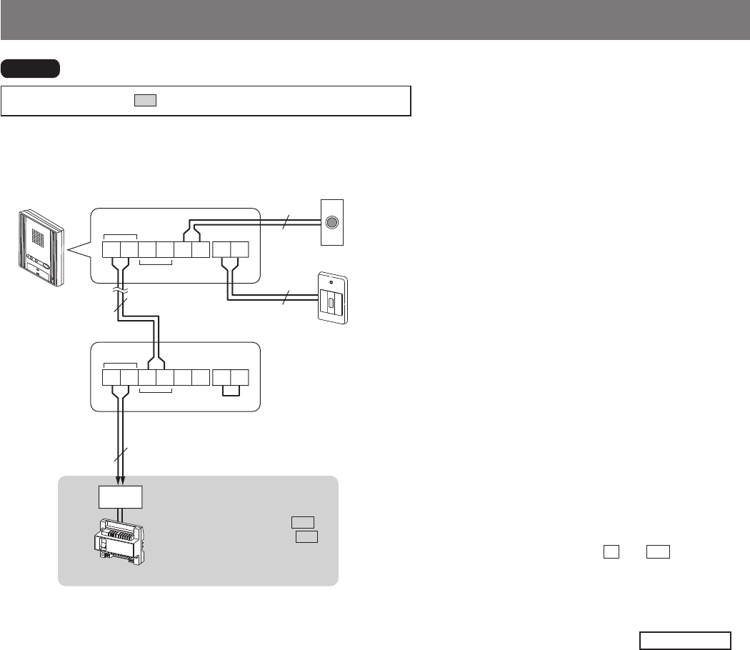
- 38 -
IN
CCE
OUT
R1 R2 R1 R2 KKE
IN
CCE
OUT
KKE
R1 R2 R1 R2
GT-BC
DP
1P
NP
1P
NP
NP
NP
Residential/tenant station (audio only)
GT-1A
GT-1A
GT-1A
* Connect to the audio bus control
unit.
Standard system: section 4-1
Expanded system: section 4-5
(No connection is needed to the
video bus control unit GT-VBC.)
NP: Non-polarized
NOTE: Refer to section 4-7 for details about wiring to the option connector.
Emergency alarm switch (*2)
(GFK-PS available in North America only.)
Doorbell (*1)
(third party product)
(*3)
(*1): Doorbell
• N/O contact (non-locked type)
• DC 12 V/0.1 A or higher
(*2): Emergency alarm switch
• N/C contact (locked type)
• DC 12 V/0.1 A or higher
(*3): Jumper wiring between K and KE .
Jumper wire must remain in place if not using an
emergency alarm switch.
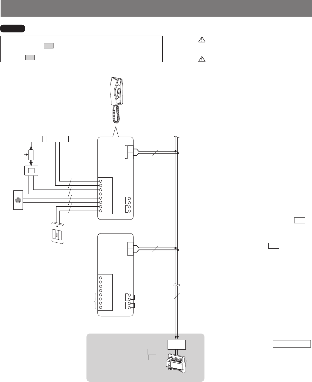
- 39 -
IN
R1
R2
C
CE
KE
RY
RY
K
CN4
SW
SW
JP1
JP4
IN
R1
R2
C
CE
KE
RY
RY
K
CN4
SW
SW
JP1
JP4
GT-BC
DP
1P
NP
1P
NP
1P
NP
NP
NP
NP
NP
AC
GT-1D
Residential/tenant station (audio only)
GT-1D
GT-1D
* Connect to the audio bus control
unit.
Standard system: section 4-1
Expanded system: section 4-5
(No connection is needed to the
video bus control unit GT-VBC.)
NP: Non-polarized
NOTES:
• Refer to section 4-7 for details about wiring to the option connector.
• To connect wires, the case must be removed from the chassis. Refer to
section 3-7 for how to remove the case.
Emergency
alarm switch (*2)
(GFK-PS
available in N.
America only)
Doorbell (*1)
(third party
product)
Turn off the GT-BC control unit before
connecting wires. Failure to do so could
damage the station.
Be careful not to damage the circuit board
when connecting wires and mounting the
station. Failure to do so could damage the
station.
(*3)
(*4)
(*1): Doorbell
• N/O contact (non-locked type)
• DC 12 V/0.1 A or higher
(*2): Emergency alarm switch
• N/C contact (locked type)
• DC 12 V/0.1 A or higher
(*3): When using an emergency alarm switch,
remove the jumper wire from the JP1
connectors. Otherwise, leave the jumper
wire connected.
When using Doctor call, remove the
jumper wire from the JP4 connectors.
Otherwise, leave the jumper wire
connected.
(*4): Only one emergency alarm switch and
one doorbell can be connected to the
same station. Each station uses its own
option connector for external devices
used for that tenant.
(*5): When making a connection to the CN4
connector, remove the protective cap.
Black
Gray
Yellow
Red
Blue
Orange
Brown
White
Option contact
output
Buzzer etc.
(*3)
GT-RY (*5)
(*5)
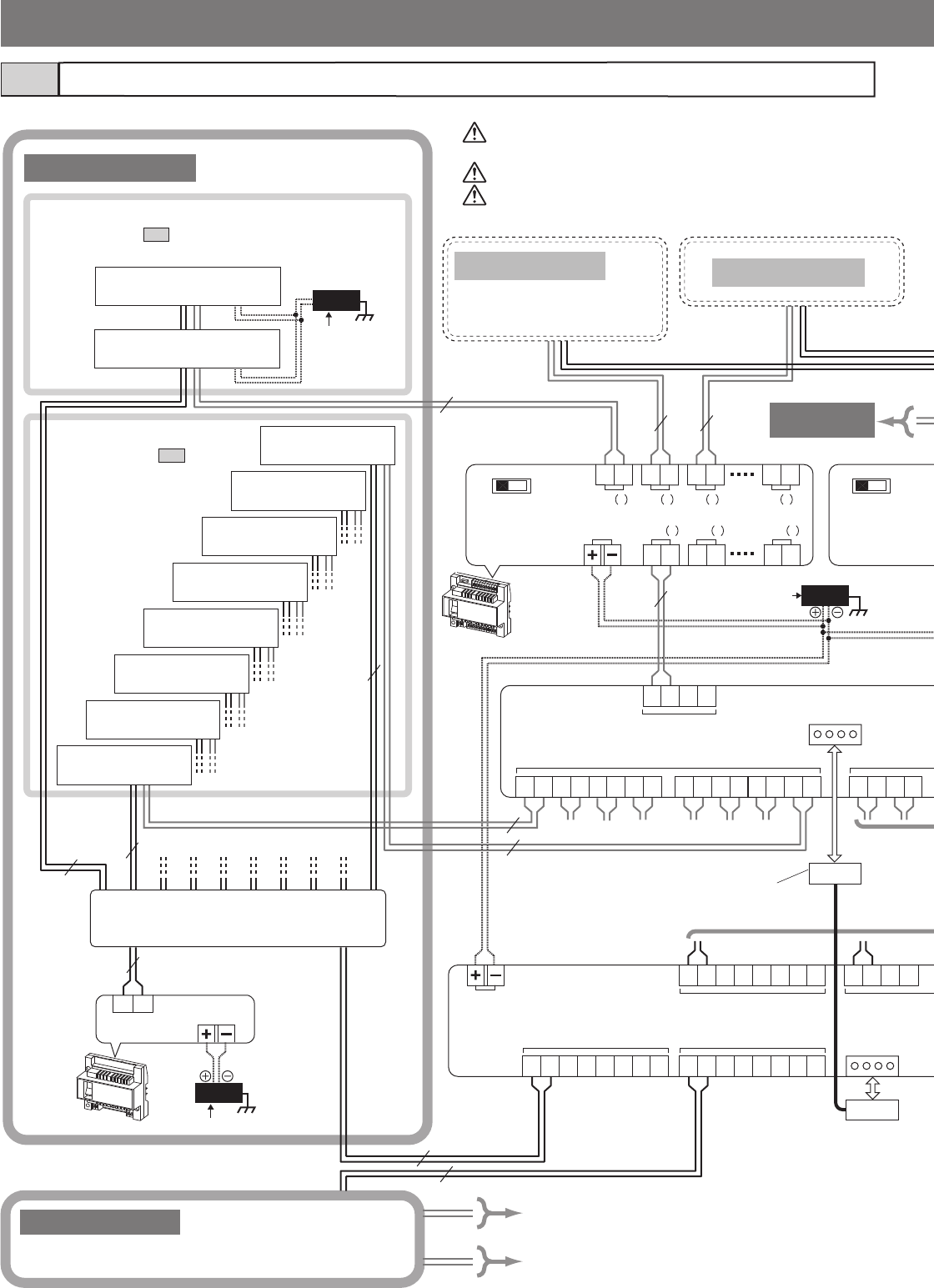
- 40 -
MAIN DC24V
A2
A1 A2
A1 A2
A1 A2
A1 A2
A1 A2
A1 A2
A1 A2
A1 A2
A1 A2
A1
COMMON1
SUB1
B2
B1 B2
B1
SUB1A
COMMON2COMMON1
R2
R1 R2
R1 R2
R1 R2
R1 R2
R1 R2
R1
R2
R1 R2
R1 R2
R1 R2
R1 R2
R1 R2
R1 R2
R1 R2
R1
CN2
CN2
MODE
EXPAND
STANDARD
OUT
IN IN IN
OUT OUT
MAIN DC24V
2
OUT
1
B2
B1 B2
B1 B2
B1 B2
B1
3 6
1 2 5
A2
A1 A2
A1 A2
A1
MODE
EXPAND
STANDARD
MAIN DC24V
R1 R2
4P
4P
PS24
AC
PS24
AC
PS24
AC
1P
NP
1P
NP
1P
NP
1P
NP
1P
NP 1P
NP
1P
NP
1P
NP
1P
NP
1P
NP
1P
NP
1P
NP
Expanded system4-5
Entrance station 5
Entrance station 6
Entrance station 7
Entrance station 8
Entrance station 4
Entrance station 3
Entrance station 2
Entrance station 1
Guard station 2
Guard station 1
Common trunk line 1
Sub trunk line 1-A
* Use the same method for connecting each common trunk line.
* Make connections in the same
method with the sub trunk line
2-B.
Guard station
* Refer to section 4-2 for detailed connection
diagrams.
Common trunk line 2
DP (Distribution Point)
(Not provided by Aiphone except for
Europe and North America.)
Use two separately jacketed 2 conductor cables for the audio
and video connections.
To prevent shorts, unused cables should be insulated.
Do not connect 2 or more GT-BC units on the same trunk line.
Entrance station
* Refer to section 4-3 for
detailed connection
diagrams.
Video bus
control unit
GT-VBC
* Connector length
40 cm (15-3/4)
Sub trunk line 1-B
To GT-VBX
To GT-VBC
GT-BC
To
Common trunk
line 2
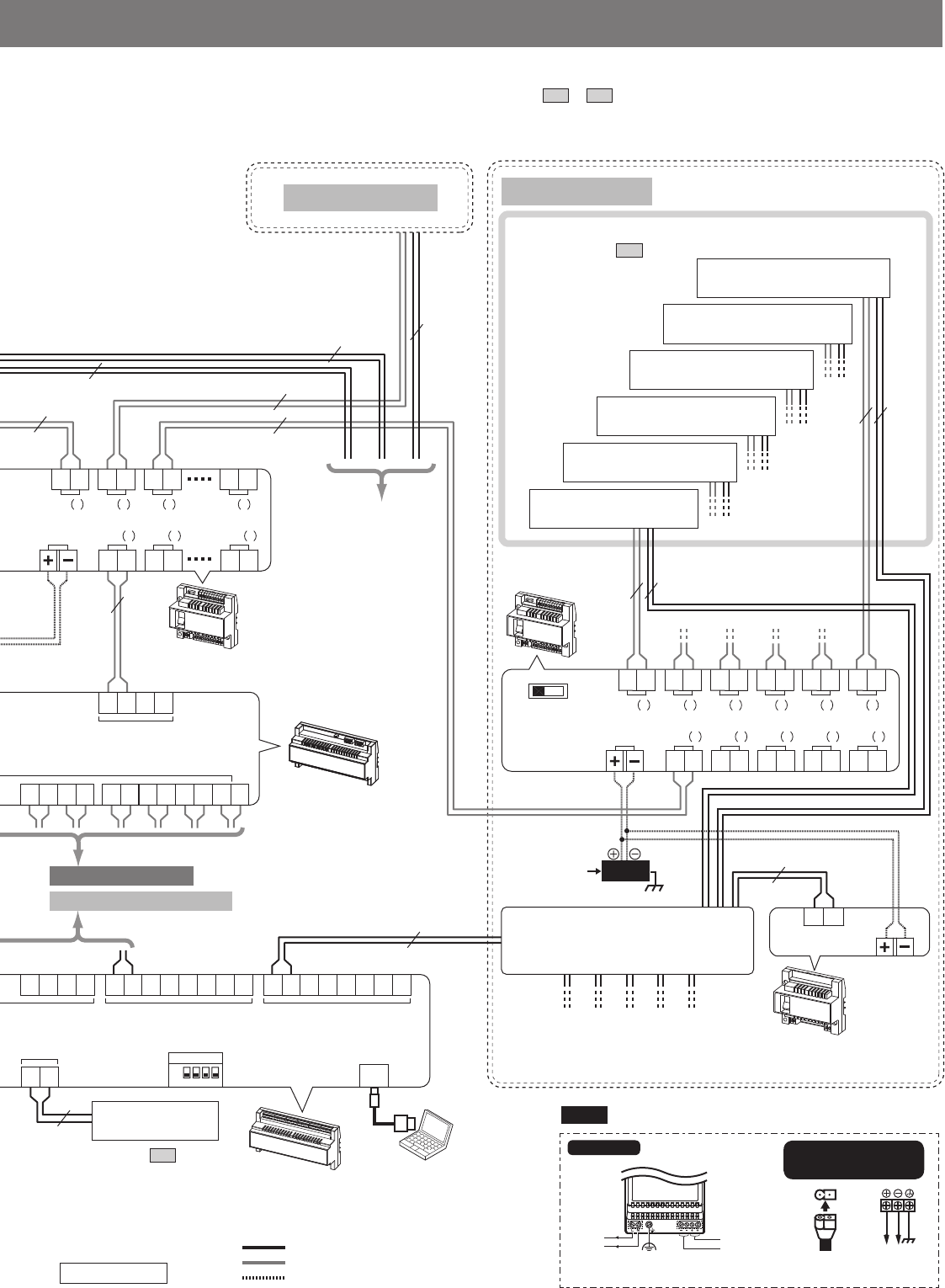
- 41 -
SUB2
A2
A1 A2
A1 A2
A1 A2
A1 A2
A1 A2
A1
COMMON2
B2
B1 B2
B1
SUB2BSUB2ASUB1B
R2
R1
R2
R1 R2
R1 R2
R1 R2
R1 R2
R1 R2
R1 R2
R1 R2
R1 R2
R1 R2
R1
GTW-LC
USB
MODE
EXPAND
STANDARD
OUT
IN IN IN IN IN
OUT OUT OUT OUT
MAIN DC24V
2
OUT
1
B2
B1 B2
B1 B2
B1 B2
B1 B2
B1 B2
B1
3456
1 2 3 4 5
A2
A1 A2
A1 A2
A1 A2
A1 A2
A1
OUT
IN IN IN
OUT OUT
MAIN DC24V
2
OUT
1
B2
B1 B2
B1 B2
B1 B2
B1
3 6
1 2 5
A2
A1 A2
A1 A2
A1
MAIN DC24V
R1 R2
PS24
AC
1P
NP
1P
NP
1P
NP
1P
NP
1P
NP
1P
NP
1P
NP
1P
NP
1P
NP
1P
NP
1P
NP
1P
NP
1P
NP
1P
NP
ON
OFF
SW2
1234
Lift control system
Expanded video bus
control unit GT-VBX
* Refer to section 4-6 for
detailed connection
diagrams.
PS24
Sub trunk line 2-B
Sub trunk line 2-A
Residential/tenant trunk
* Refer to section 4-4 for
detailed connection
diagrams.
Video bus
control unit
GT-VBC
Expanded bus
control unit
GT-BCXB-N
Bus control
unit
GT-BC
Residential/tenant trunk 6
Residential/tenant trunk 5
Residential/tenant trunk 4
Residential/tenant trunk 3
Residential/tenant trunk 2
Residential/tenant trunk 1
The following is an example of basic wiring diagram for the expanded system.
* The wiring methods differ depending on the equipment used. Refer to section 4-2 to 4-4 for detailed wiring diagrams of entrance stations,
guard stations and residential/tenant trunks.
NP: Non-polarized
: Audio signal line
: Video signal line
: Power supply line
DP (Distribution Point)
(Not provided by Aiphone except
for Europe and North America.)
GT-VBC
230 V AC 50/60 Hz 24 V DC2A
N
L
-
+
100V - 240V -
50/60 Hz
24V DC
2 A
PS-2420DM PS-2420
PS-2420S
PS-2420UL
PS-2420BF
PC
(third party product)
To
Common trunk line 2
To
Sub trunk line 1-A, 1-B, 2-A
To GT-BCXB-N
(*1)
(*1): The wires must be connected to the IN (1) terminals.
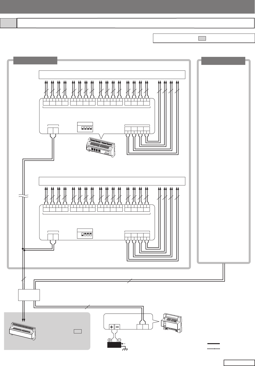
- 42 -
Lift control system (for expanded system only)4-6
R2
R1
LIFT CONTROLLER
LIFT CONTROLLER
GT-BCX
RY1 RY2 RY3 RY4 RY5 RY6 RY7 RY8 RY9
RY10 RY11 RY12 RY14RY13 RY15 RY16
RY18RY17 RY19
RY20
R2
R1
LIFT CONTROLLER
LIFT CONTROLLER
GT-BCX
RY1 RY2 RY3 RY4 RY5 RY6 RY7 RY8 RY9
RY10 RY11 RY12 RY14RY13 RY15 RY16
RY18RY17 RY19
RY20
MAIN DC24V
R1 R2
PS24
AC
DP
1P
NP 1P
NP
1P
NP
1P
NP 1P
NP 1P
NP 1P
NP
1P
NP 1P
NP 1P
NP 1P
NP 1P
NP 1P
NP 1P
NP 1P
NP 1P
NP 1P
NP 1P
NP 1P
NP 1P
NP 1P
NP 1P
NP 1P
NP
1P
NP 1P
NP 1P
NP 1P
NP
1P
NP 1P
NP 1P
NP 1P
NP 1P
NP 1P
NP 1P
NP 1P
NP 1P
NP 1P
NP 1P
NP 1P
NP 1P
NP 1P
NP 1P
NP 1P
NP
ON
OFF
ID
1 2 3 4
ON
OFF
ID
1 2 3 4
Lift control adaptor GTW-LC
* Max. 8 GTW-LC can be connected per trunk.
GTW-LC
GT-BCXB-N
Lift controller (third party product)
Lift controller (third party product)
Lift control trunk 1 Lift control trunk 2
* Connect to the expanded
bus control unit.
GT-BCXB-N.
Refer to section 4-5 for
detailed connection
diagram.
Max. 16 adaptors (GTW-LC) can be connected to a system.
* Max. 8 adaptors (GTW-LC) per trunk.
Bus control unit
GT-BC
DP: Distribution Point
(Not provided by Aiphone
except for Europe and
North America.)
NP: Non-polarized
Same as lift control trunk 1.
: Audio signal line
: Power supply line
NOTE: Refer to section 5-1 for the ID switch settings.
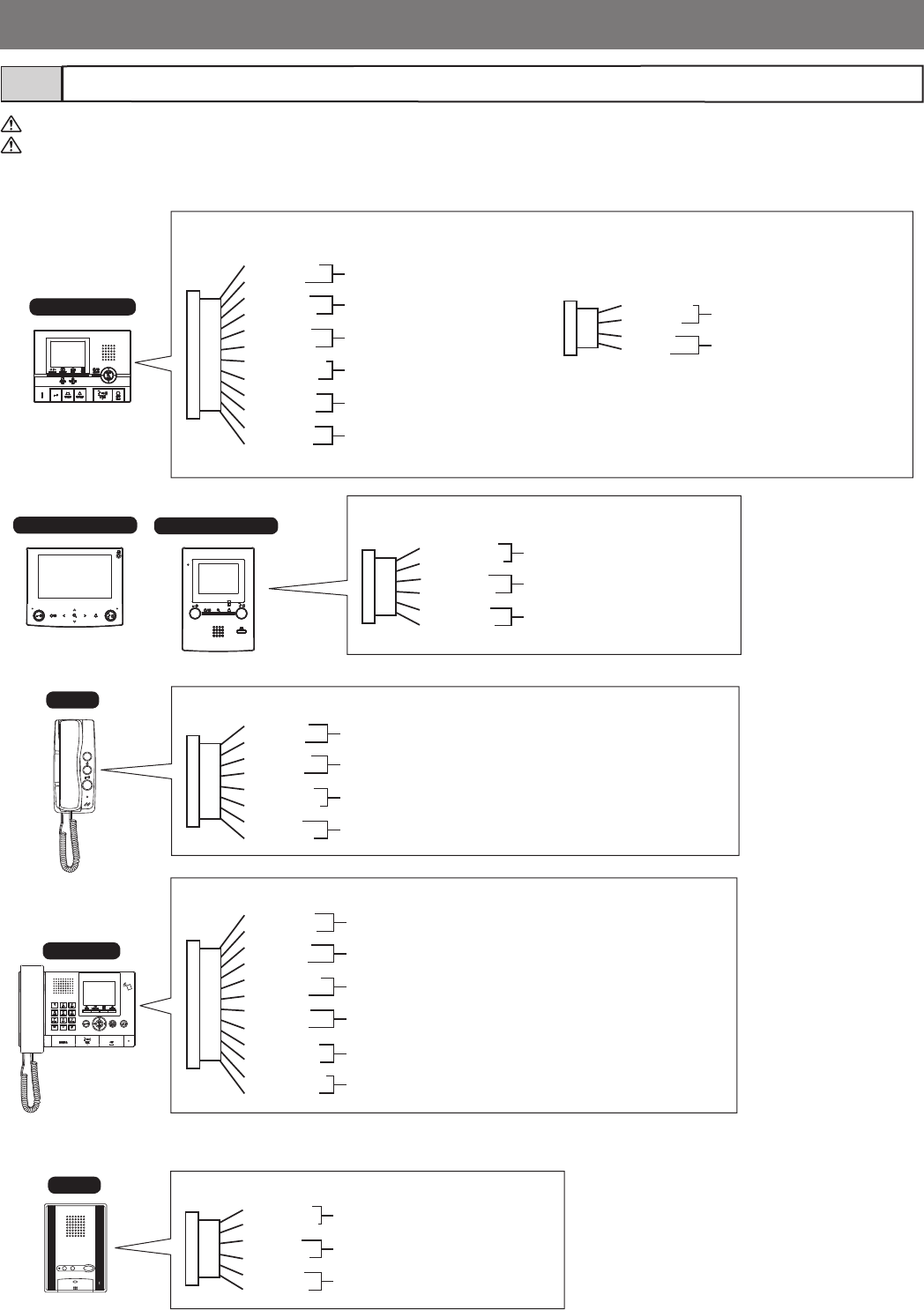
- 43 -
DC
DC
RYC
RYC
SW
SW
KE
C
K
CE
RY
RY
SW
SW
K
KE
RY
RY
SW
SW
S1
S1E
S2
S2E
S3
S3E
RYV
RYV
RYK
RYK
RYC
RYC
CE
C
SW
SW
V+
V
-
DC
DC
RY
RY
SW
SW
GT-1C7-L/GT-1C7
GT-2C-L/GT-2C
GT-1D
GT-1A
GT-MKB-N
GT-1M3-L/GT-1M3
V+
V
-
Option connector4-7
To prevent shorts, be sure to cut unused lead wires and insulate the ends.
Installation setting is necessary for the GT-2C-L/GT-2C. Refer to the GT SYSTEM Setting manual to perform the settings.
7 Doctor call (automatic entry)
2 Call notifi cation
3 Option contact output
Option connector
Option connector
(Yellow)
(Orange)
(Blue)
(White)
(Gray)
(Black)
1 Emergency alarm
2 Call notifi cation
3 Option contact output
4 Security/Utility input 1
4 Security/Utility input 2
4 Security/Utility input 3
12-pin option connector 4-pin option connector (not included)
(Brown)
(Red)
(Blue)
(White)
(Gray)
(Black)
(Orange)
(Black)
(Yellow)
(Black)
(Purple)
(Black)
(Brown)
(Red)
(Orange)
(Yellow)
5 Video out
6 Video out notifi cation
(Black)
(White)
(Gray)
(Red)
(Purple)
(Red)
(Blue)
(Red)
(Green)
(Yellow)
(Orange)
(Brown)
Option connector
8 Doorbell
5 Video out
6 Video out notifi cation
3 Option contact output
2 Emergency call notifi cation
2 Call notifi cation
(Black)
(Gray)
(White)
(Blue)
(Yellow)
(Orange)
(Red)
(Brown) 1 Emergency alarm (JP1 must be cut to use.)
8 Doorbell (JP4 must be cut to use.)
2 Call notifi cation
3 Option contact output
(Blue)
(White)
(Gray)
(Black)
(Yellow)
(Orange)
2 Call notifi cation
3 Option contact output
7 Doctor call (automatic entry)
Option connector
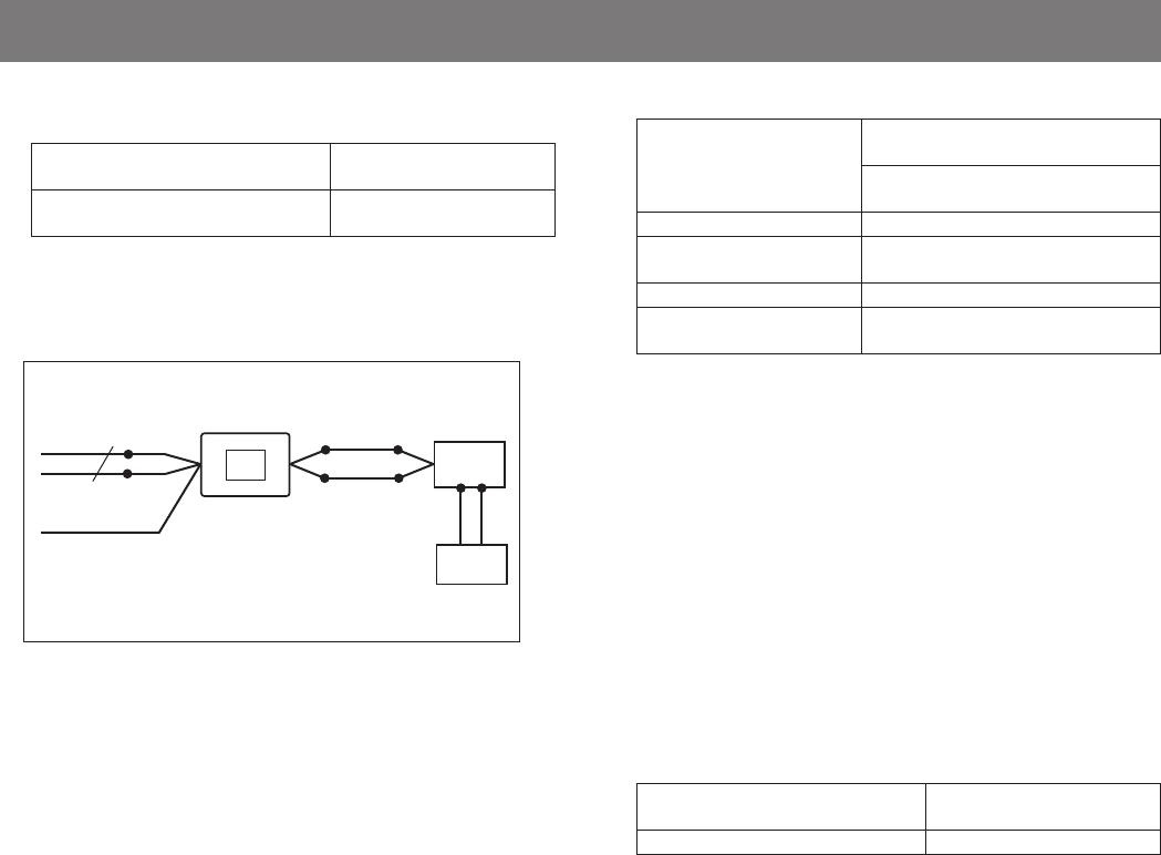
- 44 -
1 Emergency alarm
An emergency alarm switch can be connected.
GT-2C-L/GT-2C, GT-1C7-L/GT-1C7,
GT-1M3-L/GT-1M3, GT-1A, GT-1D
N/C contact (locked type)
DC 12 V/0.1 A or higher
GT-2C-L/GT-2C N/O contact (non-locked type)
DC 12 V/0.1 A or higher
2 Call notifi cation/Emergency call notifi cation
Using the external signaling relay GT-RY allows for an external
buzzer to be linked during calling.
3 Option contact output
External units such as lights or elevators can be operated with
the option button.
Contact spec.: Maximum load AC/DC 24 V, 1 A
Minimum load DC 5 V, 0.1 A
4 Security/Utility inputs 1 to 3
Input method N/O (Normally Open) or N/C
(Normally Closed) contact
External sensor input (start signal only
detection method)
Detection confi rmation time 100 msec or more
Contact resistance N/O: 1 k or less
N/C: 50 k or more
Terminal short current 1 mA or less
Voltage between terminals DC 3.3 V or less (when open between
terminals)
5 Video out
Video can be output to DVR's, etc.
NTSC, 1 Vp-p/75
Wiring distance: 3 m
NOTE: The screen playing recorded pictures is not output.
6 Video out notifi cation
External monitors can be activated via the external signaling
relay GT-RY.
GT-RY contact spec.: AC/DC 24 V, 0.5 A
7 Doctor call (automatic entry)
This makes it possible to use the doctor call (automatic entry)
function at residential/tenant stations.
To enable the doctor call:
GT-1C7-L/GT-1C7, GT-1M3-L/
GT-1M3, GT-1A
Short the DC terminal.
GT-1D Cut (open) the jumper JP4.
8 Doorbell
A doorbell can be connected to a residential/tenant station.
N/O contact (non-locked type)
DC 12 V/0.1 A or higher
NOTE: One doorbell per residential/tenant station. Do not
connect two or more doorbells to a residential/tenant
station.
(*)
(*)
NP
GT-RY
Timer
relay
Buzzer
To option
connector
White
Blue Orange
Orange
External signaling relay connection example
(*): Third party product
Black (unused)
GT-RY contact spec.: AC/DC 24 V, 0.5 A
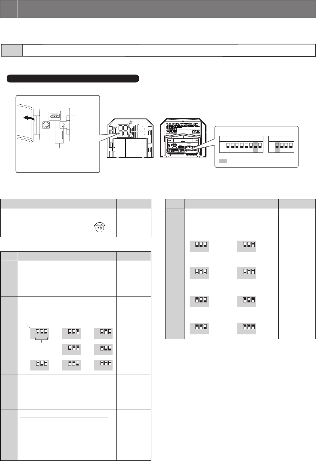
- 45 -
Switch settings5-1
The settings of each unit can be confi gured manually by setting the switches, as described below.
* It is recommended to discuss the installation and setting method with the person responsible for installation in advance.
5 SETTINGS
23
SW2
1 2 3 45 6 7 8
SW3
1 2 3 4
ON
OFF
ON
OFF
1
DIP switches
(Front) (Rear)
1 VR1 dial (inside the cover)
Function Default
Sets the door release duration time.
Setting range:
M (Momentary)/0.5-20 seconds
M
(Momentary)
2 SW2
No. Function Default
1Sets this entrance station as used for either
a multi building system or single building
system.
ON: Multi building system
OFF: Single building system
OFF
2 to 4 Sets the ID of this entrance station.
* (9) - (16): GT-BCXB-N Common trunk
line 2
2
(10)
3
(11)
5
(13)
8
(16)
4
(12)
7
(15)
6
(14)
1
(9)
ON
OFF
ON
OFF
ON
OFF
ON
OFF
ON
OFF
ON
OFF
ON
OFF
ON
OFF
2 3 4 234 2 3 4
2 3 4 2 3 4
234 234 2 3 4
2: OFF
3: OFF
4: OFF
(ID 1)
5Sets the ability of this entrance station to
be monitored by the guard station or
residential/tenant station.
ON: Allowed
OFF: Not allowed
OFF
6* This setting is needed only in France.
Set the transmission method for VIGIK.
ON: HEXACT® version
OFF: AIPHONE version
OFF
8Resets the passcode for installer or
administrator when this unit is initialized
by setting this switch to ON.
OFF
2 SW3
No. Function Default
2 to 4 Sets the language for audio guidance by
the combination of the switch 2 to 4
settings.
ON
OFF
ON
OFF
ON
OFF
ON
OFF
ON
OFF
ON
OFF
ON
OFF
ON
OFF
2 3 4 234
2 3 4 234
2 3 4 234
2 3 4 234
2: OFF
3: OFF
4: OFF
(No guidance)
■ Entrance station (modular type)
Audio module (GT-DB, GT-DB-V, GT-DB-VN)
ID number
Positions of
switch 2 to 4
(No guidance)
French
Spanish
Norwegian
English
German
Dutch
(Tone)
0.5 M
20
103
USB terminal and program switch
* Used for settings only.
(Refer to the Setting manual GT SYSTEM/
Standard & Expanded System.)
: Do not change these switches.
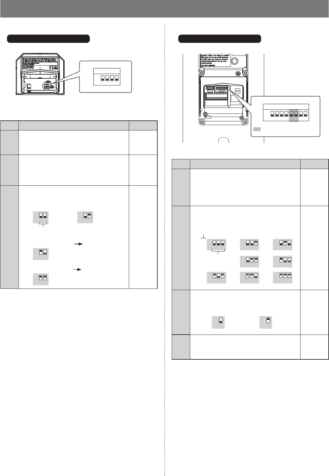
- 46 -
ON
OFF
SW1
1234
1
DIP switches
1 SW1
No. Function Default
1Sets the night illumination.
ON: Always off
OFF: Turns on/off automatically
OFF
2Sets whether surveillance camera or light is
attached.
ON: Surveillance camera
OFF: Light control
OFF
3 to 4 Sets the display mode at the beginning of a
call.
ON
OFF
ON
OFF
ON
OFF
ON
OFF
3 4 3 4
3 4
3 4
3: OFF
4: OFF
(Zoom)
Camera module (GT-VB)
Positions of switch 3 and 4
Zoom
Wide (3 seconds) Zoom
Wide
ON
OFF
1SW1
12345 6 7 8
DIP switches
■ Entrance station (all-in-one type)
GT-DMB-LVN, GT-DMB-N
1 SW1
No. Function Default
1Sets this entrance station as used for either a
multi building system or single building
system.
ON: Multi building system
OFF: Single building system
OFF
2 to 4 Sets the ID of this entrance station.
*
(9) - (16): GT-BCXB-N Common trunk line 2
2
(10)
3
(11)
5
(13)
8
(16)
4
(12)
7
(15)
6
(14)
1
(9)
ON
OFF
ON
OFF
ON
OFF
ON
OFF
ON
OFF
ON
OFF
ON
OFF
ON
OFF
2 3 4 234 234
234 234
234234 234
2: OFF
3: OFF
4: OFF
(ID 1)
7Sets the event that triggers LCD.
ON
OFF
ON
OFF
7 7
OFF
(Sensor
detection)
8Resets the passcode for the installer or
administrator when this unit is initialized by
setting this switch to ON in 2 seconds.
OFF
ID number
Positions of
switch 2 to 4
Sensor detection Operation of this unit
Zoom (3 seconds) Wide
: Do not change these switches.
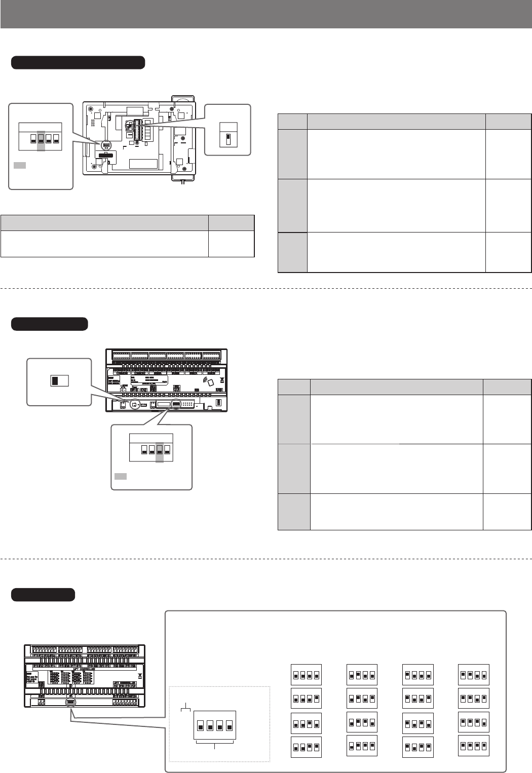
- 47 -
ON
OFF
2
1
ON
OFF
SW2
1234
ON
1234
ON
1234
ON
1234
ON
1234
ON
1234
ON
1234
ON
1234
ON
1234
ON
1234
ON
1234
ON
1234
ON
1234
ON
1234
ON
1234
ON
1234
ON
1234
1
2
3
4
5
6
7
8
9
10
11
12
13
14
15
16
ON
1234
1
DIP switch
Power switch
■ Expanded bus control unit
■ Lift control adaptor
GT-BCXB-N
GTW-LC
ID switch
Set the lift control ID number of this unit by the combination of the switch 1 to 4 settings
as shown below.
ID number
Positions of switch 1 to 4
1 Power switch
Set the switch to ON when using this unit.
2 SW2
No. Function Default
1Sets this unit as used for either a multi
building system or single building system.
ON: Multi building system
OFF: Single building system
OFF
2Sets this unit as to be used for either a
tenant section or main section.
ON: Main section
OFF: Tenant section
OFF
4Resets the passcode for installer or
administrator when this unit is initialized by
setting this switch to ON in 2 seconds.
OFF
A
B
SW1
21
SW2
1234
ON
OFF
DIP switches
■ Guard station
GT-MKB-N
2 SW2
No. Function Default
1Sets this unit as used for either a multi
building system or single building system.
ON: Multi building system
OFF: Single building system
OFF
3Sets the ID of this unit.
* (3), (4): GT-BCXB-N Common trunk line 2
ON: ID 2 (4)
OFF: ID 1 (3)
OFF
(ID 1)
4Resets the passcode for installer or
administrator when this unit is initialized by
setting this switch to ON in 2 seconds.
OFF
1 SW1
Function Default
For terminating a guard station, set SW1 to "A".
When not terminating, set to "B".
A
: Do not
change this
switch.
: Do not change this
switch.

- 48 -
GT-1C7-L/GT-1C7 GT-1M3-L/GT-1M3 GT-2C-L/GT-2C
SW2
SW2
SW2
ON
12 3 45 6 7 8
SW2
A
B
A
B
A
B
2
SW1
1
A
B
Switch settings (for residential/tenant stations only)5-2
Setting method
1 Change the decimal notation ID to binary to set the
residence ID.
• 1 indicates (ON) and 0 indicates (OFF).
• For binary notation, refer to the DIP switch & ID list for
residential/tenant stations(*1) in the setup tool and perform
settings as shown below.
2 • Create a correlation table with the setup tool
between the ID set for residences/tenants and the
residential/tenant station names and upload this to
the entrance station or guard station.
* For information on how to use the setup tool, see the GT
SYSTEM Setting Manual and Aiphone GT Setup Tool
for Windows on the Aiphone website.
Saving programmed data and resident information data to
your PC is recommended.
• In addition, set up the system for the entrance
station(s), guard station(s), and residential/tenant
stations. (Refer to the GT SYSTEM Setting
Manual.)
(*1): The DIP switch & ID list for residential/tenant station is
available from the Aiphone website.
Aiphone website: http://www.aiphone.net/
NOTE: Refer to the GT SYSTEM Setting Manual for
confi guring the system setup.
1
2
3
4
0000 0001
0000 0010
0000 0011
0000 0100
0011 0000
1111 1010
48
250
Binary notation
Decimal notation
DIP switches
2 SW2
Residential/tenant stations must be linked to entrance/guard stations
for enabling calling and communication.
All video residential/tenant stations can have "UNIT Link-ID" set by
using SW2.
Function Default
The DIP switches of SW2 must be used when
setting UNIT Link-IDs by using the "Manual
Setting" method.
If using the "Automatic Setting" method, do not
change the default setting "0000 0000".
• Automatic setting:
Set the DIP switches to "0000 0000".
The UNIT Link-ID is set automatically.
* For GT-1D and GT-1A, UNIT Link-ID is
always set automatically.
• Manual setting:
Set the UNIT Link-ID by using the DIP
switches.
Decide the UNIT Link-IDs in advance, and
coordinate with the system installer for SW2
DIP switch settings.
NOTE:
If there is mixture of video and audio residential/
tenant stations in the site, only Automatic setting
should be used.
1: OFF
2: OFF
3: OFF
4: OFF
5: OFF
6: OFF
7: OFF
8: OFF
(0000 0000)
How to set "UNIT Link-ID"
There are two methods for link setting.
By Hand-
shaking
The entrance/guard stations must be put into
programming mode and communication must
be established one-by-one with each resident
station. Either "Automatic setting" or "Manual
setting" is available.
By GT Setup
Tool
Every residential/tenant station must be set
with a unique residence UNIT Link-ID, as
shown below. Link establishment is performed
with the GT setup tool. Only the "Manual
setting" for UNIT Link-IDs is available. The
DIP swiches on SW2 must be set in advance.
1 SW1
Function Default
To terminate a residential/tenant
station, leave SW1 set to "A".
Otherwise, set to "B".
* Refer to section 4 "WIRING"
for details about the SW1 settings.
A
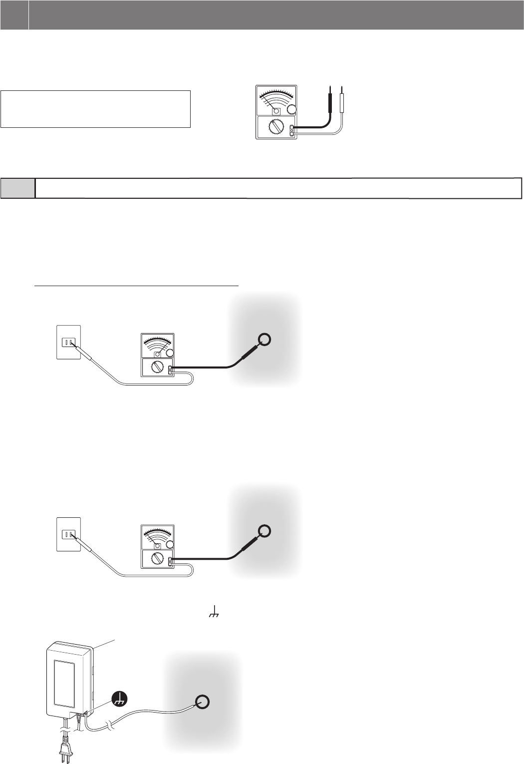
- 49 -
1 Set the tester for 250V AC or more.
2 Find the "hot" side of the AC outlet to be connected with a power plug.
2-1. Put one tester rod to the point that seems to be a grounding point.
2-2. Touch the other tester rod contact to one of the AC outlet slots to fi nd the side where the tester needle swings.
The side where the tester needle swings is the "hot" side.
3 Find the proper grounding point.
3-1. With one tester rod put on the “hot” side, put the other to the point that seems to be a grounding point.
* If the needle swings to the power supply value for your country, it will be considered a proper grounding point.
If the needle does not reach the power supply value, it will not be considered a proper point.
3-2. Find the grounding point by repeating this step until the needle points to the proper value.
4 Connect the power supply ground terminal [ ] with the grounding point found in step 3.
When checking operation after system installation shows a malfunction in spite of no error in equipment terminal connections, check for the
following "grounding point" and "ground fault" in wiring.
Tools required: Analog tester
NOTES:
• A digital tester cannot make a precise reading.
• A megohmmeter cannot be used.
6
CHECK FOR INSTALLATION
Finding a proper "grounding point" for power supply6-1
“Hot” side?
Actual “Hot” side
Grounding point
Actual grounding point
Actual grounding point
Power supply
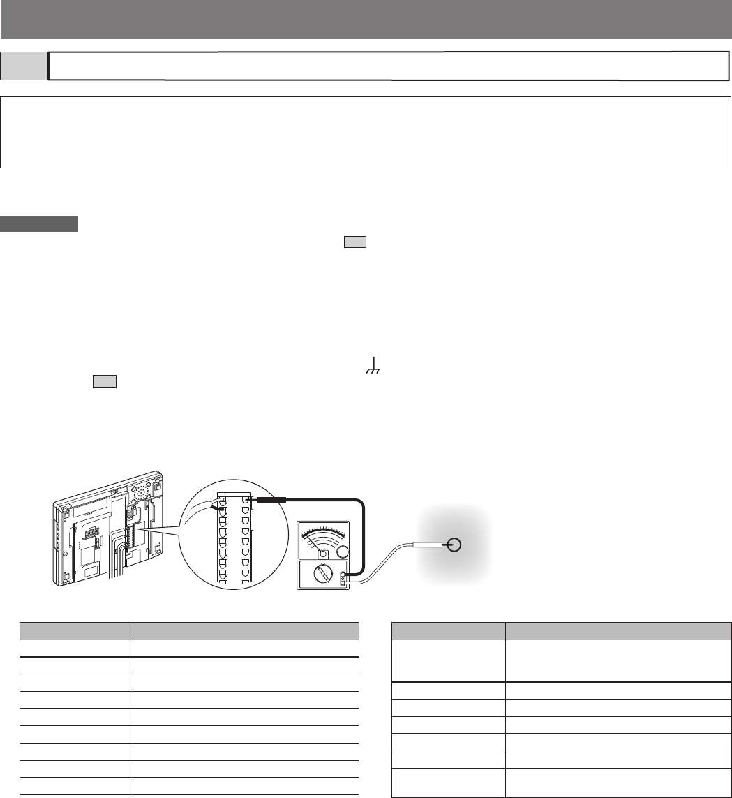
- 50 -
What is “ground fault”?
"Ground fault" means the state where internal copper wire is touching a metal part (ground) in the building because the coating on the wiring
of the intercom system is peeled off. This may cause the equipment to malfunction. Being in the ground fault state, the whole system will be
damaged seriously by a "power surge."
Inspection conditions:
Important
• Check that the power supply is grounded properly as described in 6-1 .
• Before starting inspection, make sure all control units (GT-BC, GT-VBC, GT-BCXB, GT-VBX), entrance station, and guard station are turned
on. (Only when the equipment is installed)
Inspection procedure:
1 Set the tester for around 50V DC.
2 Put one tester rod to the power supply ground terminal [ ]. If the power supply is not nearby, fi nd a grounding point
referring to 6-1 .
3 With one tester rod put on the power supply ground terminal, put the other to the following terminals to be
inspected.
4 If the tester needle does not swing in step 3, it will be judged "no ground fault.".
* If the tester needle swings, there is a ground fault in wiring between the power supply and the inspected point.
(The same is true in the case where the needle swings reversely.)
Solution:
Divide the wiring into sections or trunk lines, identify the ground fault point, and remove the cause.
Checking "ground fault" with tester6-2
Product name Terminal to be inspected
GT-BC All [R1] and [R2]
GT-BCXB-N All [R1] and [R2]
GT-VBC All [A1], [A2], [B1] and [B2]
GT-VBX All [A1], [A2], [B1] and [B2]
GT-MCX [R1], [R2], [A1], [A2], [B1], [B2]
GT-VB [A1], [A2]
GT-DB(-V, -VN) [R1], [R2]
GT-DMB(-V, -LVN) [R1], [R2], [A1], [A2]
GT-MKB-N [R1], [R2], [A1], [A2], [B1], [B2]
Product name Terminal to be inspected
GT-2C(-L)
GT-1C7(-L)
GT-1M3(-L)
All [R1], [R2], [B1] and [B2]
GT-1A, GT-1D All [R1] and [R2]
GT-4Z All [R1], [R2], [B1] and [B2]
GT-1Z All [B1] and [B2]
GTW-LC [R1], [R2]
JO-DV [A1], [A2]
DP (Distribution
Point)
(Each line)
Power supply ground terminal or
grounding point
(e.g. GT-1C7)

- 51 -
REGULATIONS
FCC
This device complies with part 15 of the FCC Rules. Operation is subject to the following two conditions: (1) This device may not
cause harmful interference, and (2) this device must accept any interference received, including interference that may cause
undesired operation.
NOTE: This equipment has been tested and found to comply with the limits for a Class B digital device, pursuant to part 15 of the
FCC Rules. These limits are designed to provide reasonable protection against harmful interference in a residential installation.
This equipment generates, uses and can radiate radio frequency energy and, if not installed and used in accordance with the
instructions, may cause harmful interference to radio communications. However, there is no guarantee that interference will not
occur in a particular installation. If this equipment does cause harmful interference to radio or television reception, which can be
determined by turning the equipment off and on, the user is encouraged to try to correct the interference by one or more of the
following measures:
• Reorient or relocate the receiving antenna.
• Increase the separation between the equipment and receiver.
• Connect the equipment into an outlet on a circuit different from that to which the receiver is connected.
• Consult the dealer or an experienced radio/TV technician for help.
INDUSTRY CANADA
CAN ICES-3 (B)/NMB-3(B)
WEEE
The object area of is the EU.

Issue date: Jun. 2017
FK1679 E P0617 SZ 59036
WARRANTY
Aiphone warrants its products to be free from defects of material and workmanship under normal use and service for a period of 2
years after delivery to the ultimate user and will repair free of charge or replace at no charge, should it become defective upon
which examination shall disclose to be defective and under warranty. Aiphone reserves unto itself the sole right to make the fi nal
decision whether there is a defect in materials and/or workmanship; and whether or not the product is within the warranty. This
warranty shall not apply to any Aiphone product which has been subject to misuse, neglect, accident, power surge, or to use in
violation of instructions furnished, nor extended to units which have been repaired or altered outside of the factory. This warranty
does not cover batteries or damage caused by batteries used in connection with the unit. This warranty covers bench repairs only,
and any repairs must be made at the shop or place designated in writing by Aiphone. This warranty is limited to the standard
specifi cations listed in the operation manual. This warranty does not cover any supplementary function of a third party product that
is added by users or suppliers. Please note that any damage or other issues caused by failure of function or interconnection with
Aiphone products is also not covered by this warranty. Aiphone will not be responsible for any costs incurred involving on site
service calls. Aiphone will not provide compensation for any loss or damage incurred by the breakdown or malfunction of its
products during use, or for any consequent inconvenience or losses that may result.
AIPHONE CO., LTD., NAGOYA, JAPAN
http://www.aiphone.net/
