Aiphone Sheet LEF 1309 Selective Door Release
Aiphone Intercom System LAF-10 LEF-1309-Selective-Release
User Manual: Aiphone LEF-1309 Selective Door Release Product Guide
Open the PDF directly: View PDF ![]() .
.
Page Count: 2

SYSTEM/MODEL: LEF
MODIFICATION: Selective door release on the LEF system
COMPONENTS REQUIRED: 1. LEF-5, LEF-10, or LEF-10S master station.
*The S.O.P. LEF-3L master station can also be used.
2. RY-PA relay: One per door being released.
3. Door station: Any LE- or LS- series.
INSTR/OPERATIONS: 1. Install stations as per instructions provided with units.
2. Connect RY-PA relays as shown on diagram.
3. The "K#" terminals shown in the diagram are available only on the LEF-
5/5C/10/10S/10C masters. (LEF-3L has colored wires.) They are not
provided on the optional LEW-series desktop terminal boxes. If LEW-
series terminal boxes are required, connect door release wires directly to
master, bypassing the LEW terminal boxes.
REFERENCE DRAWING #: 0998-1309
DIFFICULTY LEVEL: 2 - Easy/moderate - Component connection to external points.
Aiphone’s product warranty applies to products properly modified using these instructions.
However, if a unit is damaged as a result of improper modification, the warranty does not apply.
- INSTRUCTIONS -
The LEF 5- and 10-call master stations are equipped with selective door release capability (as well
as the S.O.P. model LEF-3L). The door release button on the master station will release the door
corresponding with the door station where communication is established.
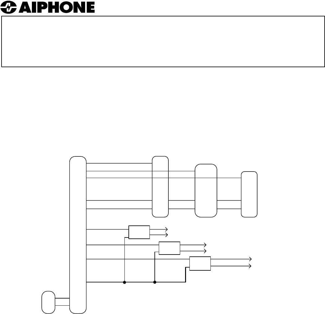
LEF INTERCOM SYSTEM WITH SELECTIVE DOOR RELEASE
LEF-5 LEF-10/10S
LEF-5C LEF-10C
NOTES:
1. On the LEF master station, the extra outputs are labeled K1 ~ K5 or K1 ~ K10. In a system
with selective door release, an RY-PA relay is required for each door to be released.
2. If multiple masters are used within a system and all masters need to activate the door release,
connect the K terminals between master stations.
3. Only wiring concerning selective door release is shown here. For complete system
installation information, please refer to the standard LEF instructions.
1
2
3
~
10
E
-
K1
K2
K3
L
+
-
LEF Master
+
-
PS-1225UL
LE-D*
1
E
-
Red
Blk
Grn
LS-NVP*
1
E
-
LE-DA*
RY-PA
#1
RY-PA
#2
RY-PA
#3
BLK
BLK
BLK
YEL
YEL
YEL
Door strike and power for station #1
Door strike and power for station #2
Door strike and power for
station #3
Drawing Name:
1309-LEF-Sel DR
Drawing # 0798-1309
WIRING DIAGRAM:
Common (+12V DC when door
release button is pressed)
Selective control
(grounded when
corresponding
station button is
pressed).
* Any LE- or
LS-series
door station
can be used.
