AirM2M Communication Technology A6501 WIFI module User Manual Manual
Shanghai AirM2M Communication Technology Co., Ltd WIFI module Manual
UserManual.wiki
>
AirM2M Communication Technology
>
A6501 User Manual
Manual
Navigation menu
Upload a User Manual
Namespaces
Wiki Guide
HTML
PDF
Info
Views
User Manual
Discussion / Help
Navigation


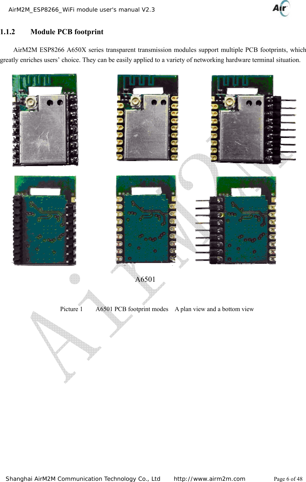
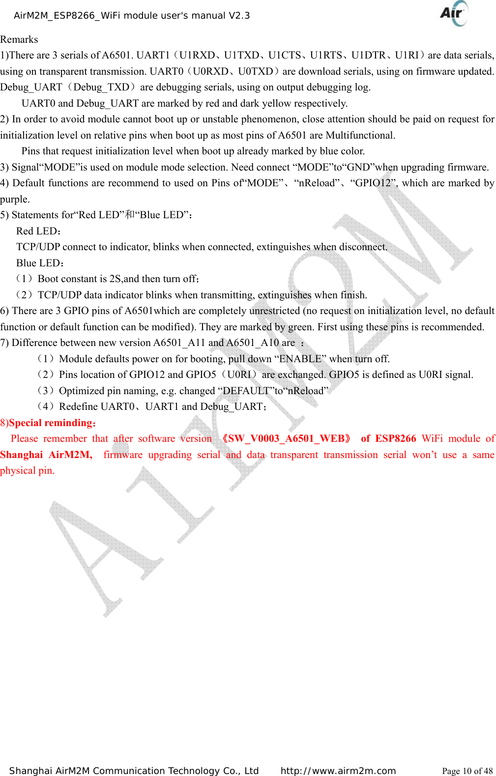
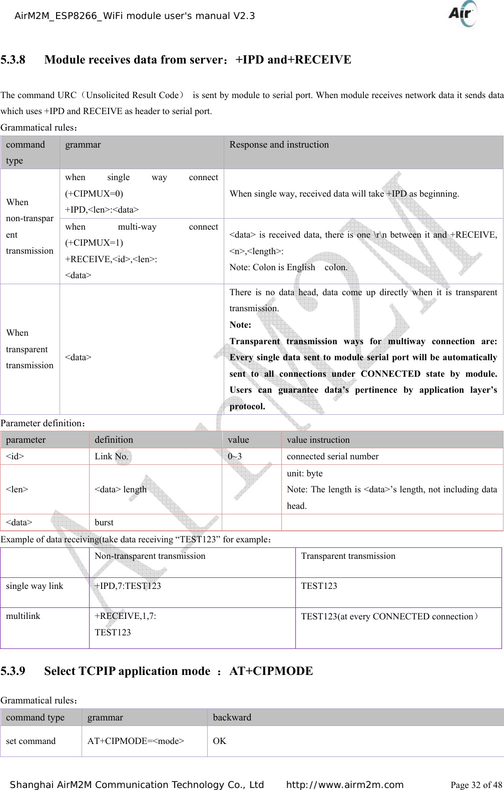
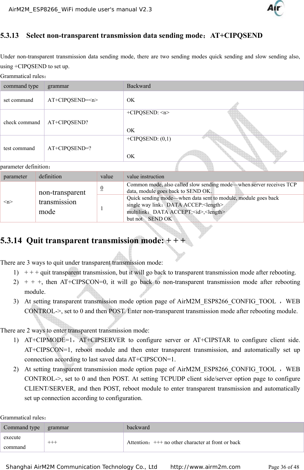
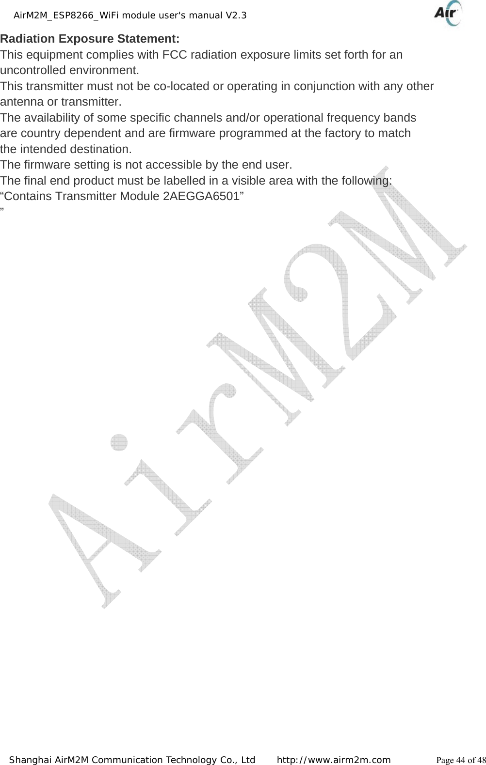
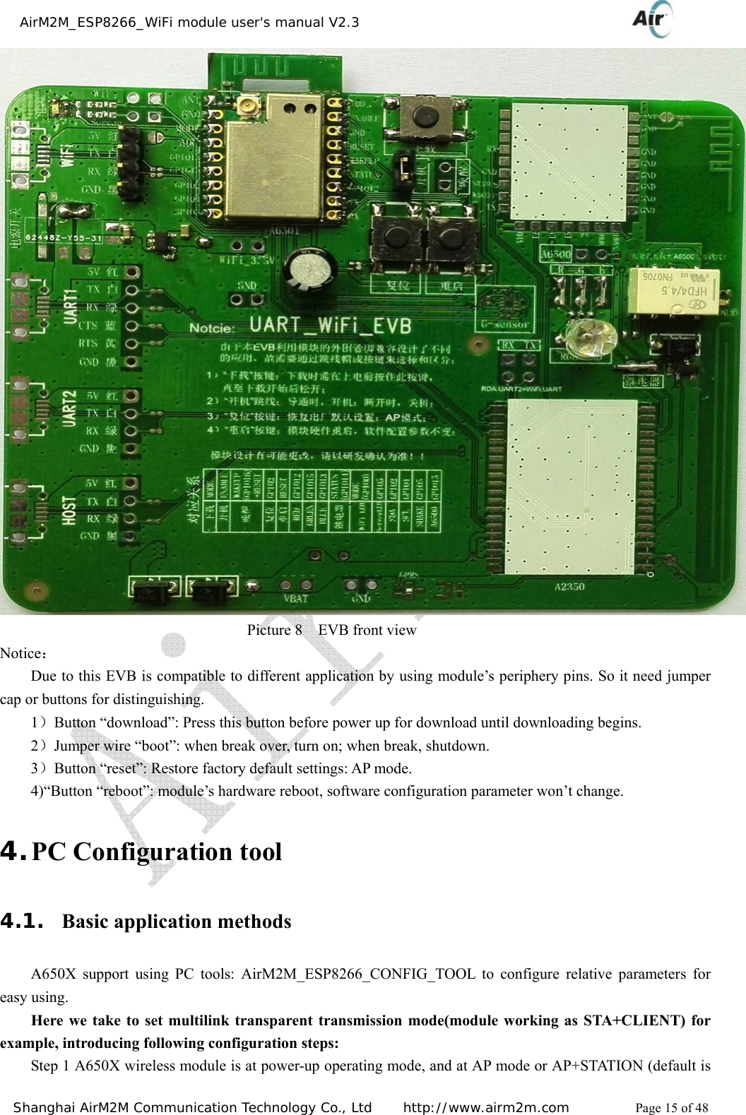
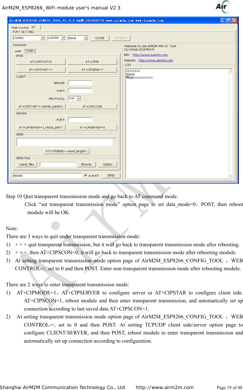
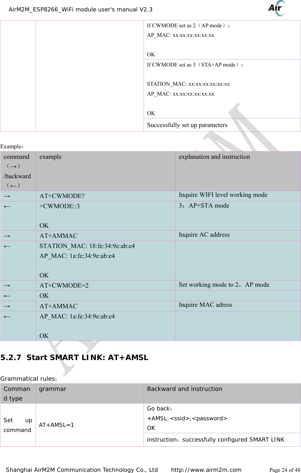
![AirM2M_ESP8266_WiFi module user's manual V2.3 Shanghai AirM2M Communication Technology Co., Ltd http://www.airm2m.com Page 11 of 48 1.3. Power consumption All the following power consumption data gained basing on 3.3V, 25° (temperature). [1] All the tests are completed at the antenna interface. [2] All emit data gained at continuous emission mode, basing on 90% of duty ratio. Mode Min Normal Max unit transmit 802.11b,CCK 1Mbps,Pout=+19.5dBm 215 mA transmit 802.11b,CCK 11Mbps,Pout=+18.5dBm 197 mA transmit 802.11g,OFDM54 Mbps,Pout=+16dBm 145 mA transmit 802.11n,MCS7,Pout=+14dBm 135 mA receive 802.11b,package length is 1024 bytes,-80dBm 60 mA receive 802.11g,package length is 1024 bytes,-70dBm 60 mA receive 802.11n,package length is 1024 bytes,-65dBm 62 mA System standby mode 0.9 mA Deep sleep 10 μA Energy-saving mode DTIM1 1.2 mA Energy-saving mode DTIM3 0.86 mA Shutdown 0.5 μA Table 5 Power consumption data](https://usermanual.wiki/AirM2M-Communication-Technology/A6501/User-Guide-2583778-Page-11.png)
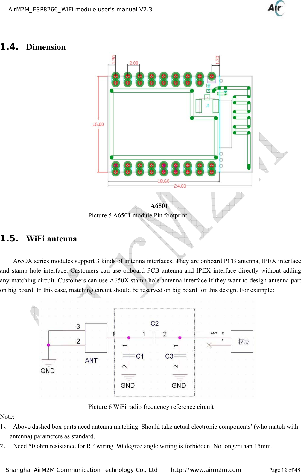
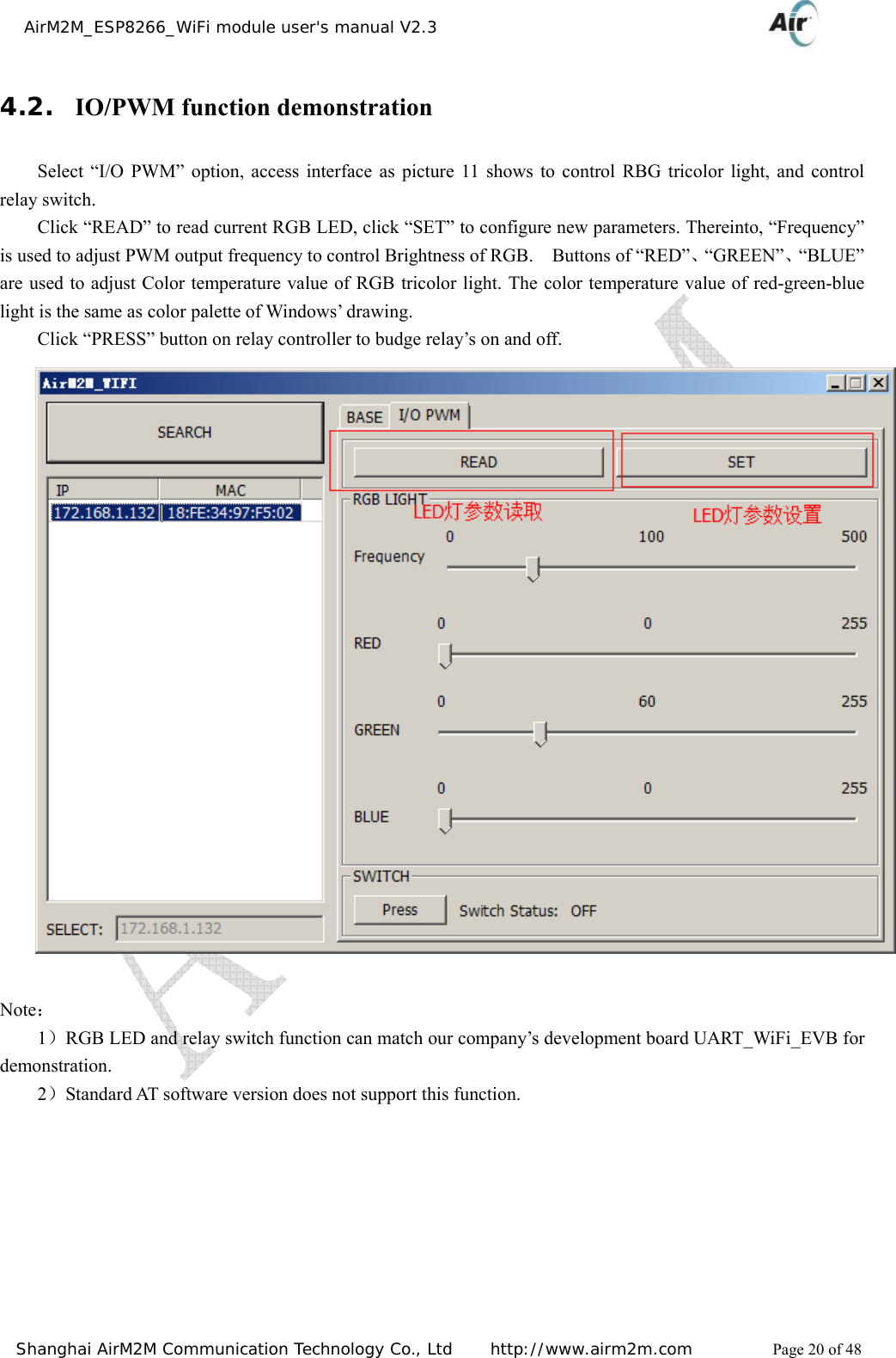
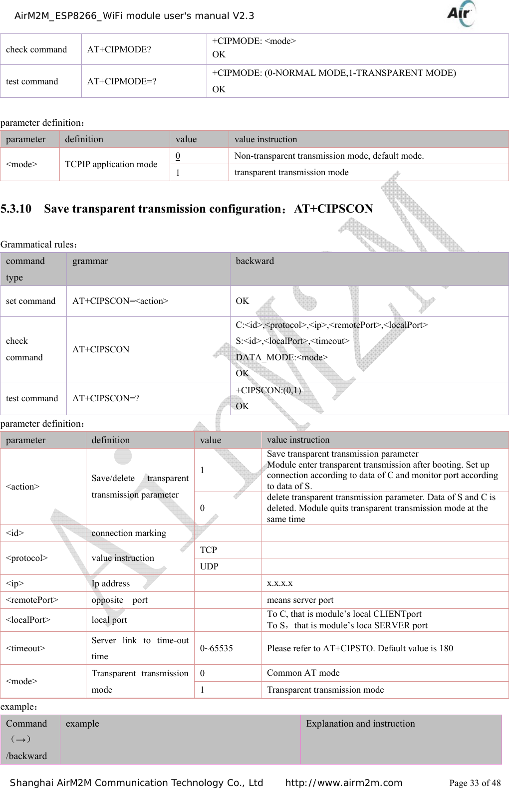
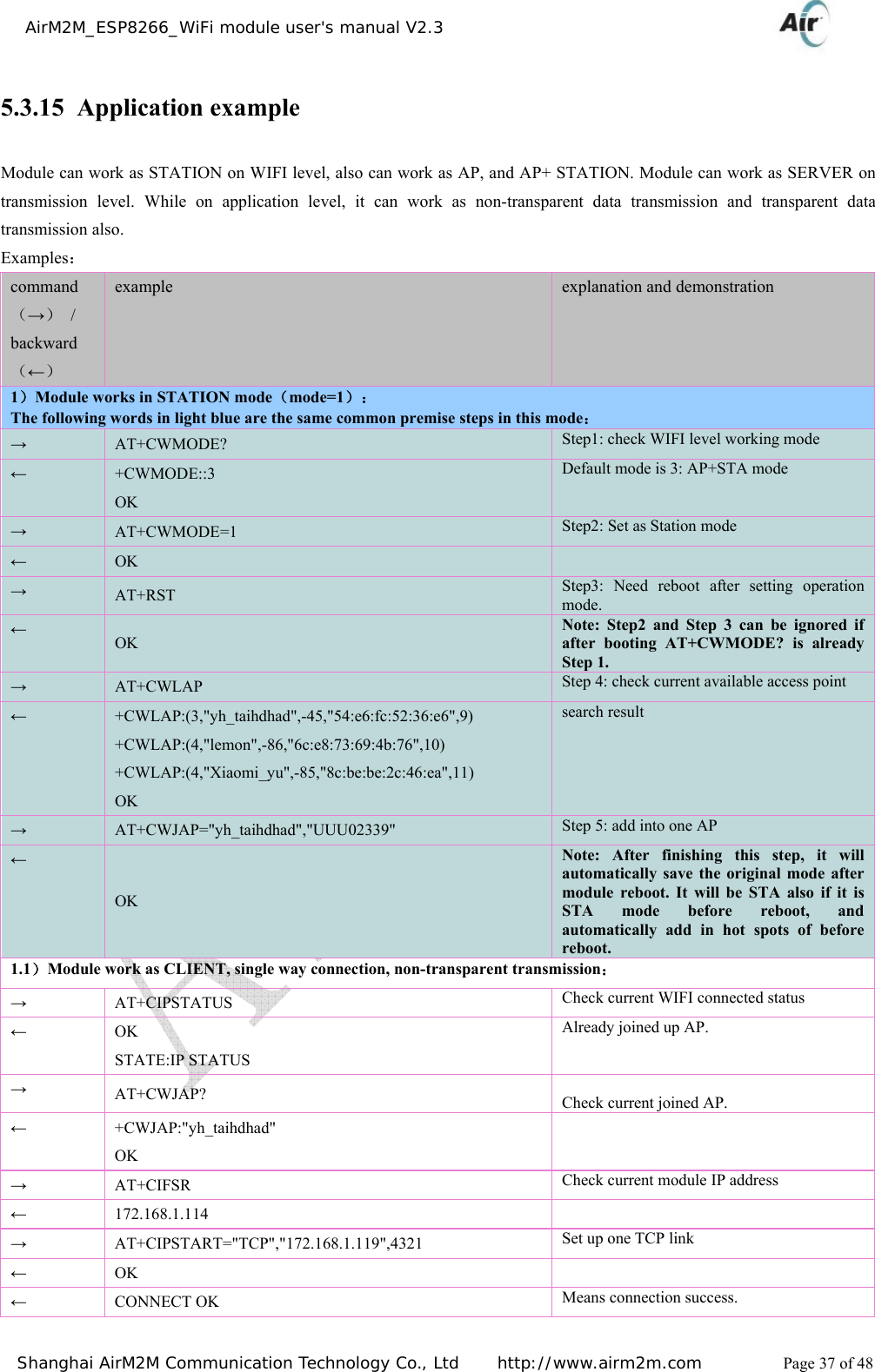
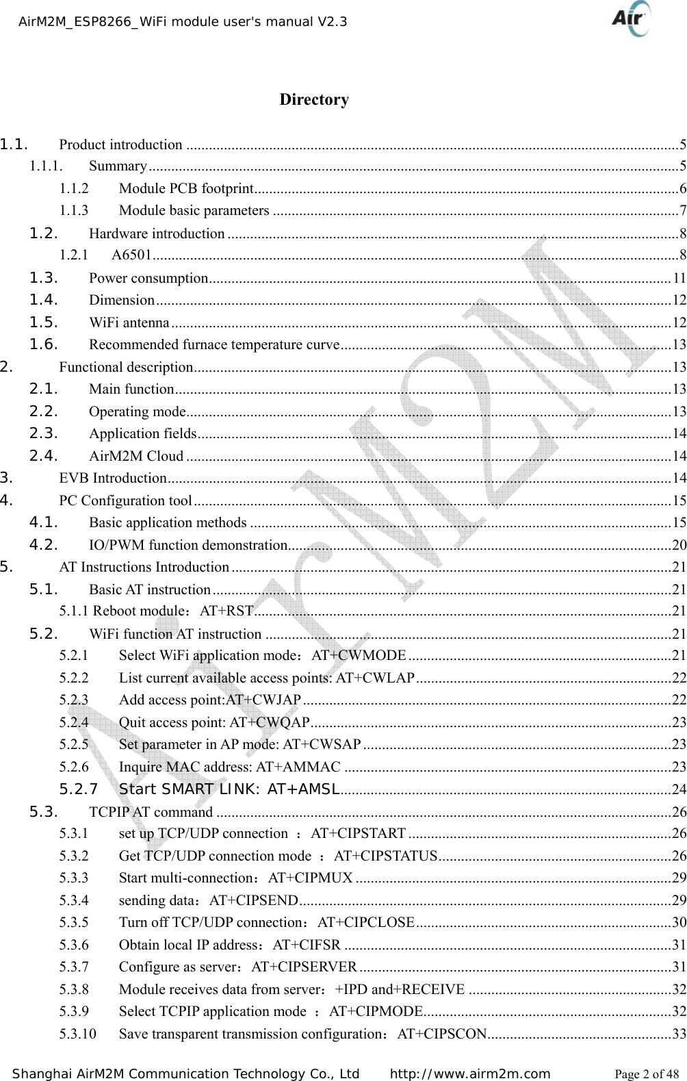
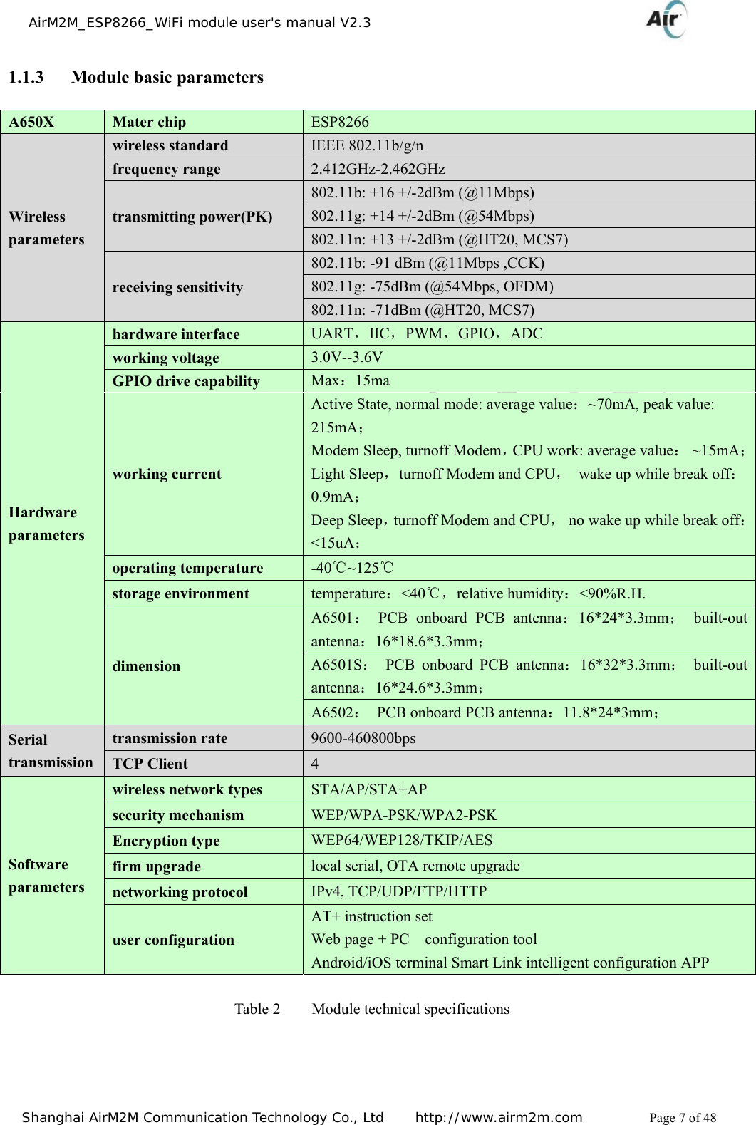
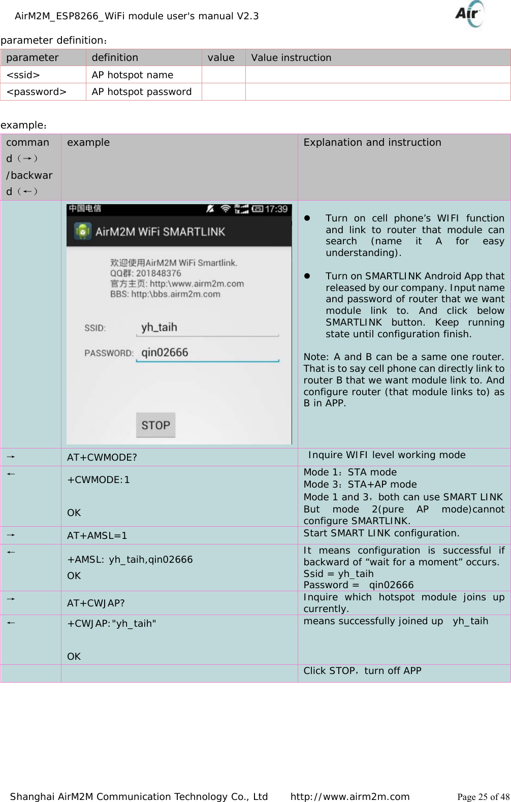
![AirM2M_ESP8266_WiFi module user's manual V2.3 Shanghai AirM2M Communication Technology Co., Ltd http://www.airm2m.com Page 22 of 48 5.2.2 List current available access points: AT+CWLAP Grammatical rules: command type grammar backward and instruction execute command AT+ CW LAP +CWLAP: <ecn>,<ssid>,<rssi>[,<mode>] OK this command will go back to AP list Parameter definition: parameter definition value value instruction <ecn> encryption way 0 OPEN 1 WEP 2 WPA_PSK 3 WPA2_PSK 4 WPA_WPA2_PSK <ssid> access point name character string parameter <rssi> signal strength <mode> connect mode 0 manual connect 1 automatic connection 5.2.3 Add access point:AT+CWJAP Grammatical rules: command type Grammar Backward and instruction Set command AT+CWJAP=<ssid>,<pwd> OK or ERROR Successfully join AP, go back to OK. If not, go back to ERROR check command AT+ CW JAP ? +CWJAP:<ssid> OK go back to current choice AP Parameter definition: parameter definition value value instruction <ssid> access point name character string <pwd> password character string, the longest is 64 byte, ASCII coding](https://usermanual.wiki/AirM2M-Communication-Technology/A6501/User-Guide-2583778-Page-22.png)
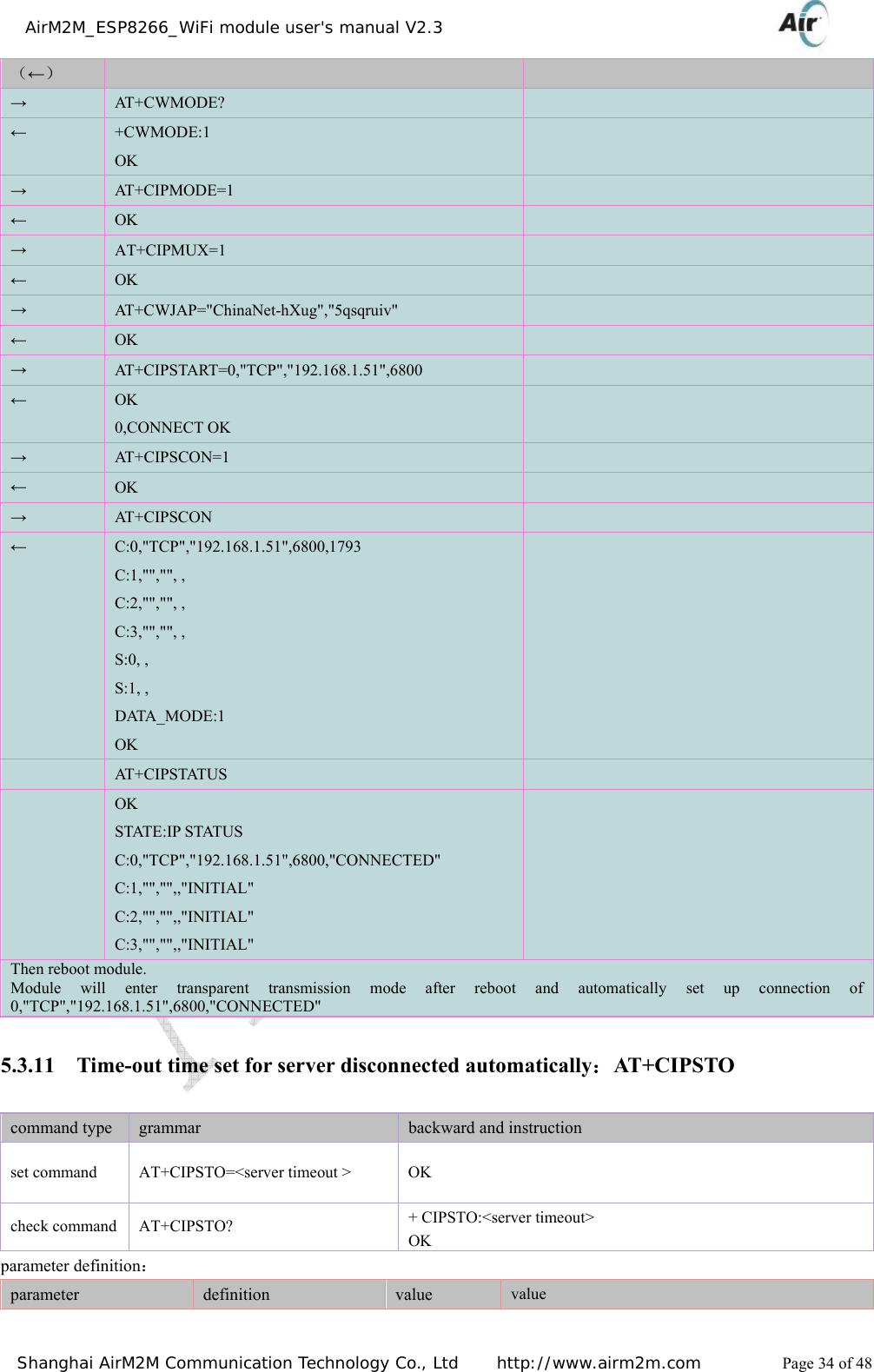
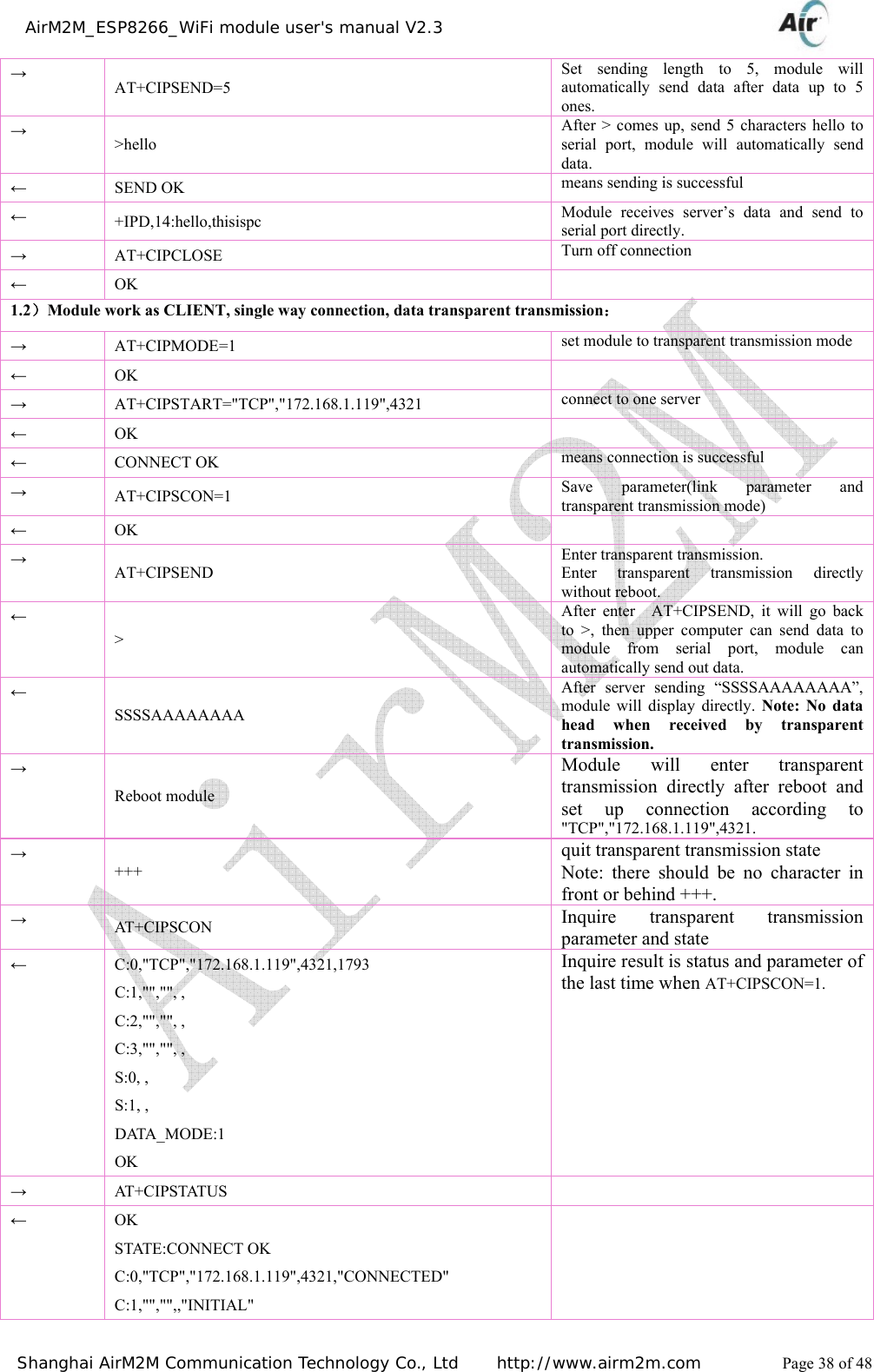
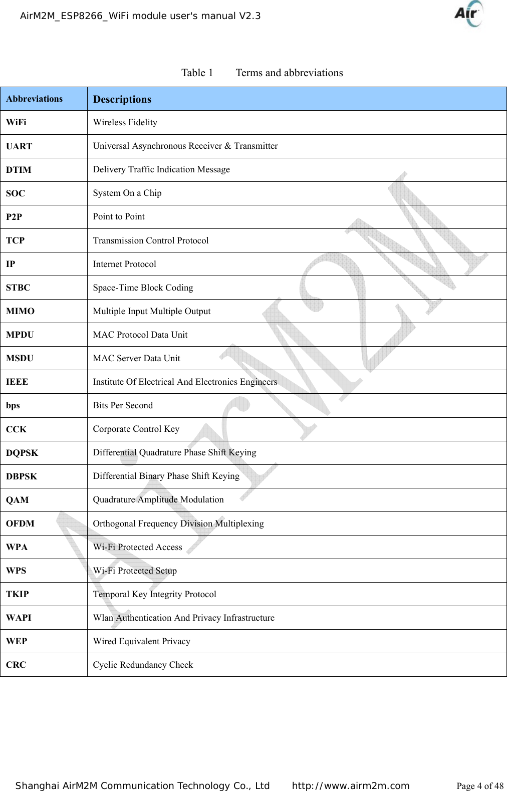
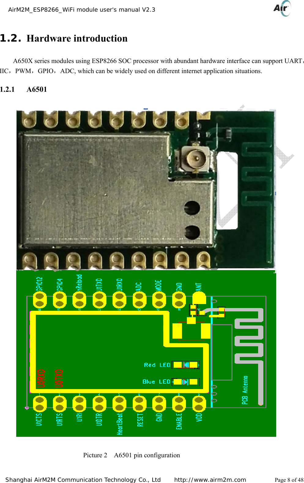
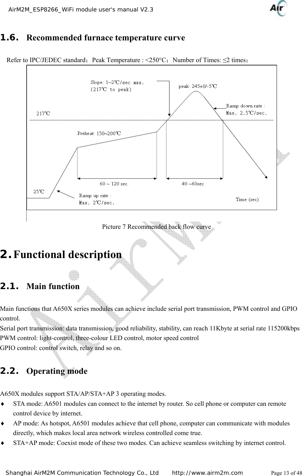
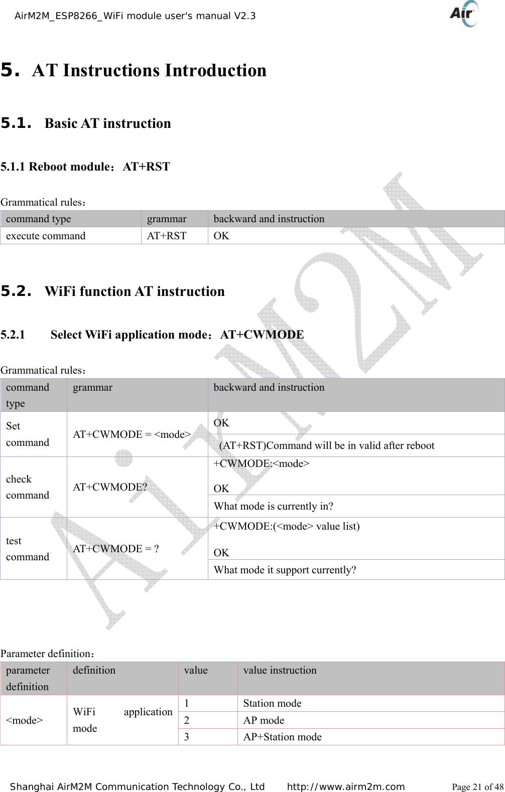
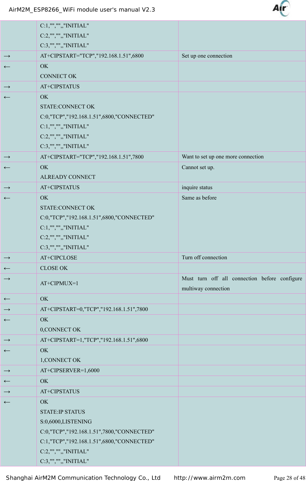
![AirM2M_ESP8266_WiFi module user's manual V2.3 Shanghai AirM2M Communication Technology Co., Ltd http://www.airm2m.com Page 26 of 48 5.3. TCPIP AT command 5.3.1 set up TCP/UDP connection :AT+CIPSTART Grammatical rules: command type grammar backward and instruction set command when single way connection (+CIPMUX=0): AT+CIPSTART=<type>,<addr>,<port>,[local_port] When multichannel connection: AT+CIPSTART=<id>,<type>,<addr>,<port>,[local_port] And local port is optional parameters if format is right, go back: OK otherwise go back: +CME ERROR: invalid input value successfully connect, go back: CONNECT OK (CPIMUX=0) <id>, CONNECT OK (CIPMUX=1) If connection already exist, go back: ALREADY CONNECT connection fail, go back: CONNECT FAIL (CIPMUX=0) <id>, CONNECT FAIL (CIPMUX=1) parameter definition: parameter definition value value instruction <id> Link No. 0~4 means connected serial number. server / 0 connection can be connected by client or server, other ID can use on remote server connection only. <type> connection type “TCP”/”UDP” <addr> Remote server IP address character string <port> remoter service port number [local_port] local port number, can select parameters 5.3.2 Get TCP/UDP connection mode :AT+CIPSTATUS Grammatical rules: command type grammar backward and instruction execute command AT+CIPSTATUS If it is single way connection (AT+CIPMUX=0), go back to OK STATE: <sl_state> C:<cid>, <TCP/UDP>, <IP address>, <port>, <client state> Note: If it is single way connection, it uses following way for connection:](https://usermanual.wiki/AirM2M-Communication-Technology/A6501/User-Guide-2583778-Page-26.png)
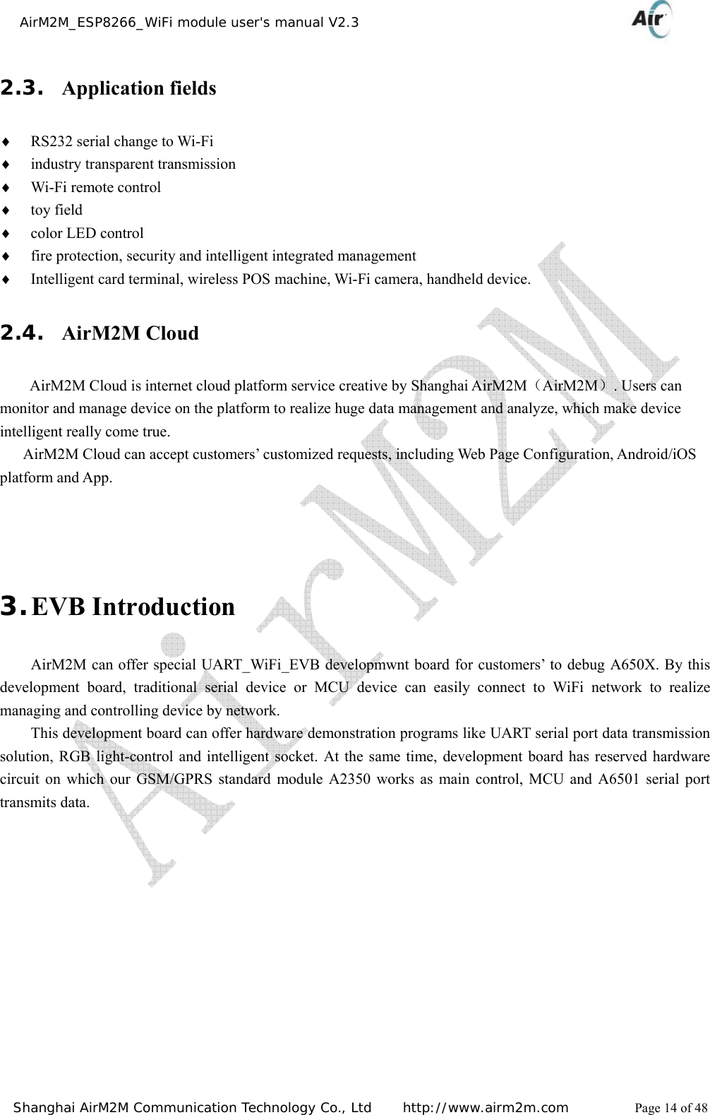
![AirM2M_ESP8266_WiFi module user's manual V2.3 Shanghai AirM2M Communication Technology Co., Ltd http://www.airm2m.com Page 27 of 48 AT+CIPSTART=<type>,<addr>,<port>,[local_port] way, and one link can be set up only. Occupied <cid> = 0 If it is multiway connection (AT+CIPMUX=1), go back toOK STATE:<ml_state> S: <sid>,<port>,<server state> C:<cid>, <TCP/UDP>, <IP address>, <port>, <client state> test command AT+CIPSTATUS=? backward: OK parameter definition: parameter definition value value instruction <sl_state> single way connection state IP INITIAL initialization IP STATUS obtain local IP status TCP CONNECTING/UDP CONNECTING TCP connecting/UDP port registering CONNECT OK successfully connect setup TCP CLOSING/UDP CLOSING Shutting down TCP connection, and logging out UDP port. <sid> server ID 0~1 value 0 and 1 <server state> server status OPENING turning on LISTENING monitoring CLOSING turning off <cid> customer’s ID 0~3 value as 0,1,2,3 <IP address> IP address - character string parameters(need quotation mark for character string) <port> server monitor port number - integer type <client state> customer’s status INITIAL turn off state CONNECTING connecting CONNECTED connected example: Command backward(←) example Explanation and instruction → AT + C W M O D E ? Inquire WIFI level working mode ← +CWMODE::3 OK 3:AP+STA mode → AT+CIPMUX? ← +CIPMUX:0 OK Single way connection mode → AT +C IPSTAT US ← OK STATE:IP STATUS C:0,"","",,"INITIAL"](https://usermanual.wiki/AirM2M-Communication-Technology/A6501/User-Guide-2583778-Page-27.png)
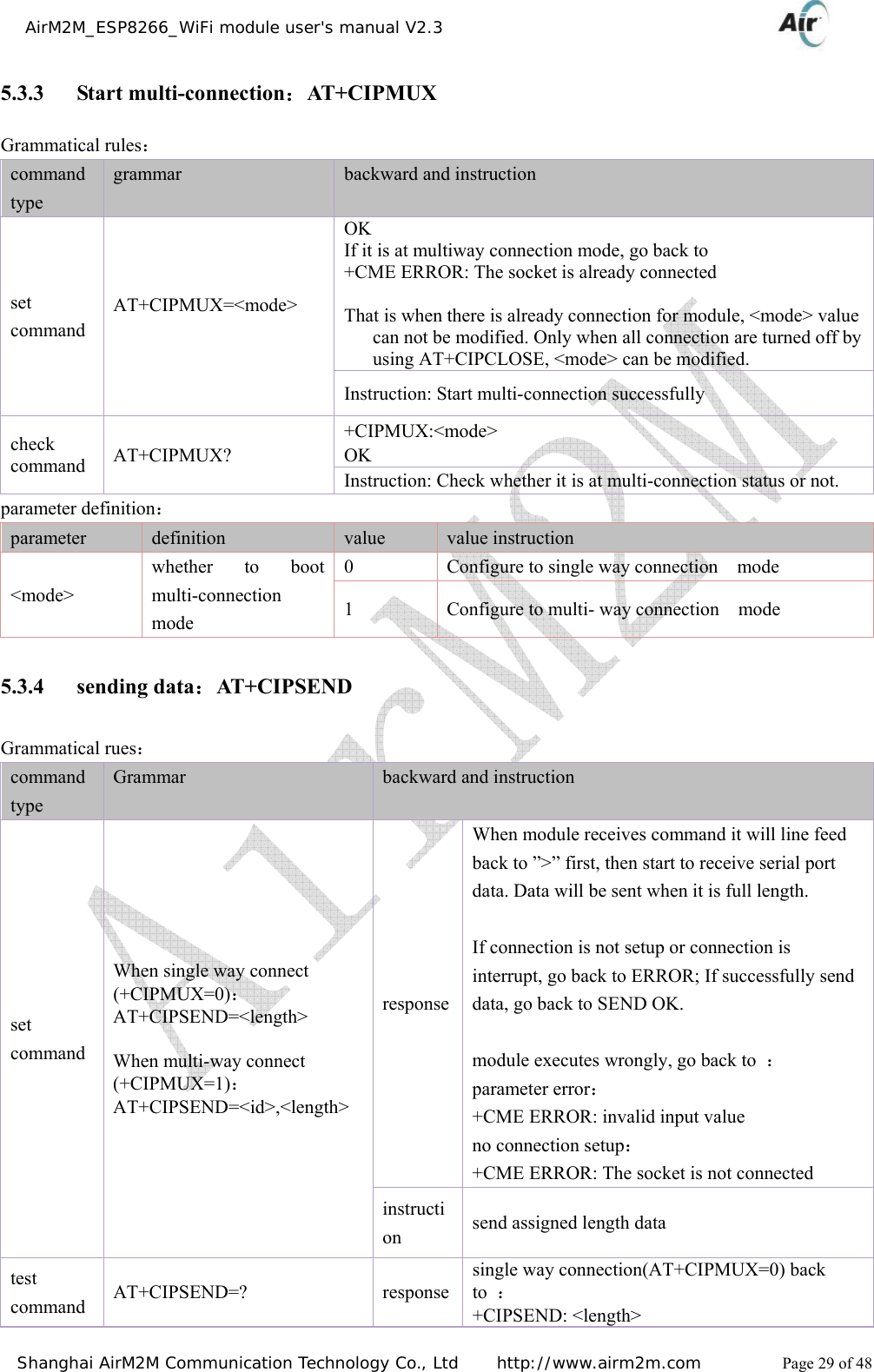
![AirM2M_ESP8266_WiFi module user's manual V2.3 Shanghai AirM2M Communication Technology Co., Ltd http://www.airm2m.com Page 30 of 48 OK multi-way connection(AT+CIPMUX=1) back to :+CIPSEND: <0-7>,<length> OK execute command AT+CIPSEND instruction AT+CIPMODE=1 and as customer-side mode, to access into transparent transmission mode(need support hardware flow control, otherwise data will be lost when there is mass data.) When module receives command it will line feed back to ”>” first, then start to send data which received by serial port. Parameter definition: parameter definition value value instruction <length> data length unit: byte <id> Link No. 0~3 connect serial number 5.3.5 Turn off TCP/UDP connection:AT+CIPCLOSE Grammatical rules: command type grammar backward and instruction set command Single way connection AT+CIPCLOSE=<id> go back: CLOSE OK Multi-way connection AT+CIPCLOSE=<n>[,<id>] go back: <n>,CLOSE OK execute command AT+CIPCLOSE If shut down successfully, go back: CLOSE OK If shut down fail, go back: ERROR test command AT+CIPCLOSE=? go back: OK Items need attention z Executing command is effective to single way connection, it will go back to ERROR when multi-way connection. z When executing command AT+CIPCLOSE, connection will be shut down only when at TCP/UDP CONNECTING or CONNECT OK status, otherwise it will take shut down for fail and go back to ERROR. z Status after shutting down is IP CLOSE when at single way connection mode. parameter definition: parameter definition value value instruction <id> shut down mode 0 slow shutdown(default value) 1 quit shutdown <n> Link No. 0~3 integer type, means connected serial number](https://usermanual.wiki/AirM2M-Communication-Technology/A6501/User-Guide-2583778-Page-30.png)
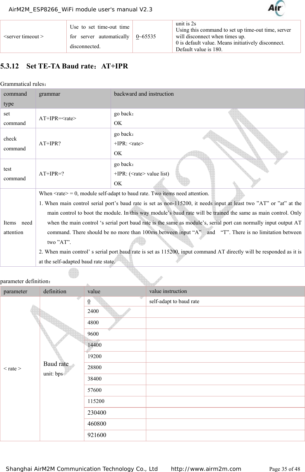
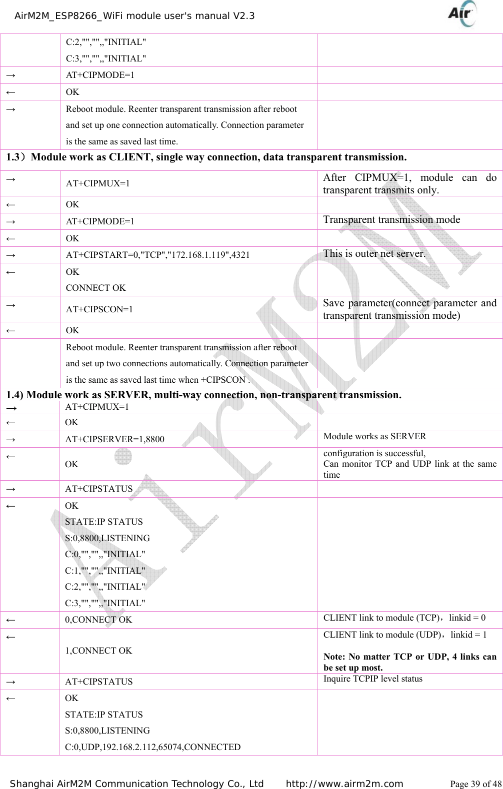
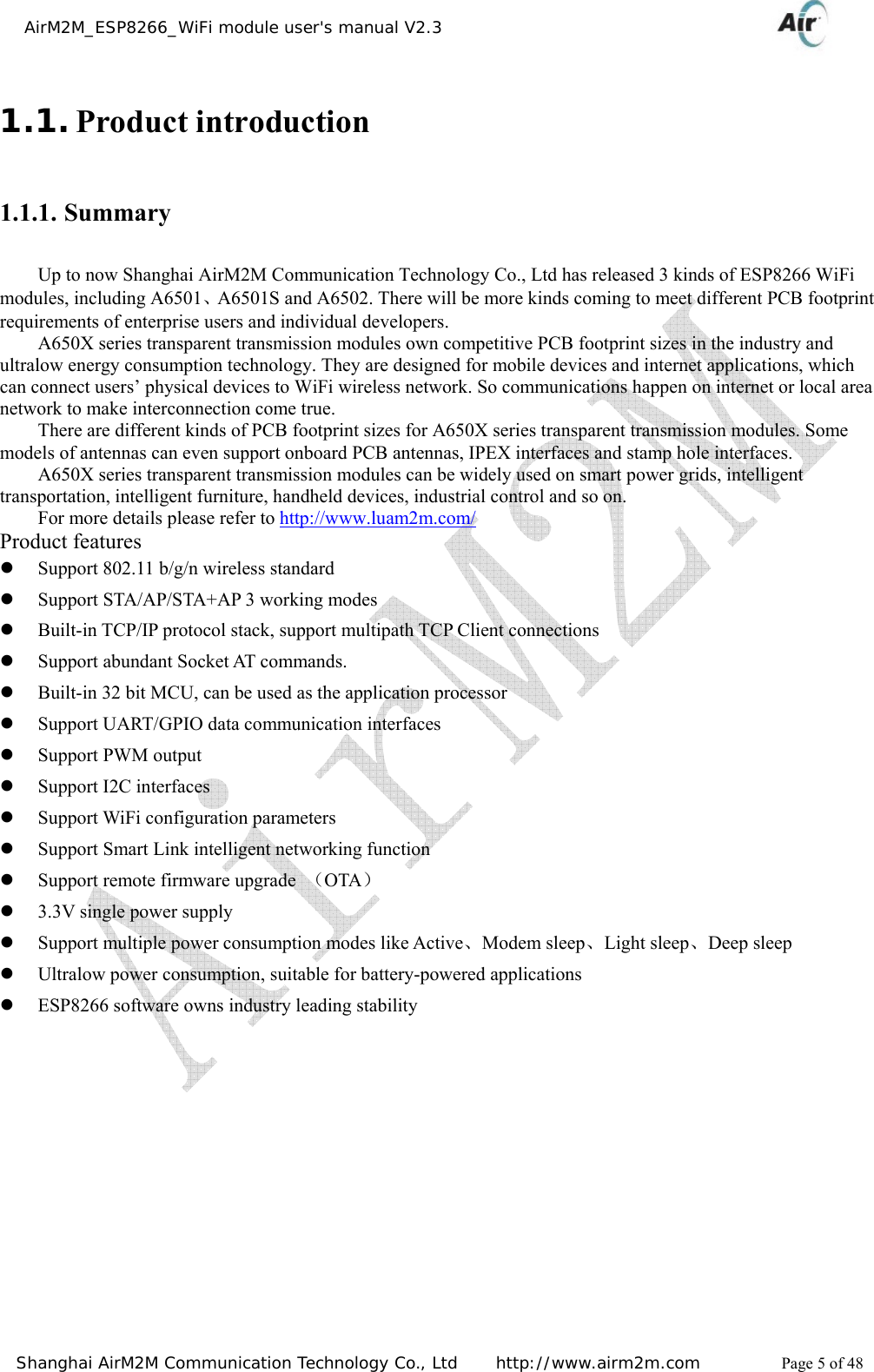
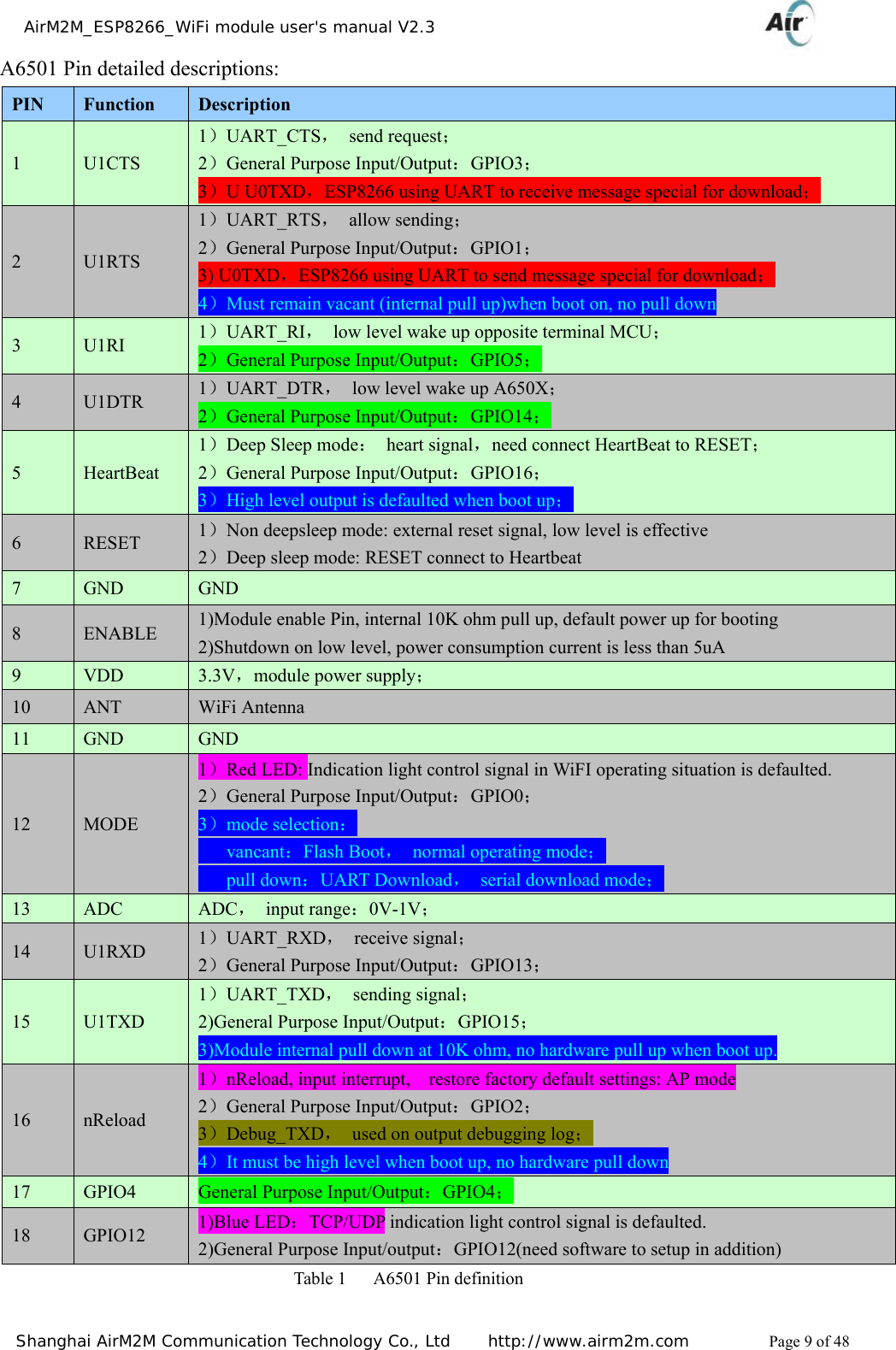
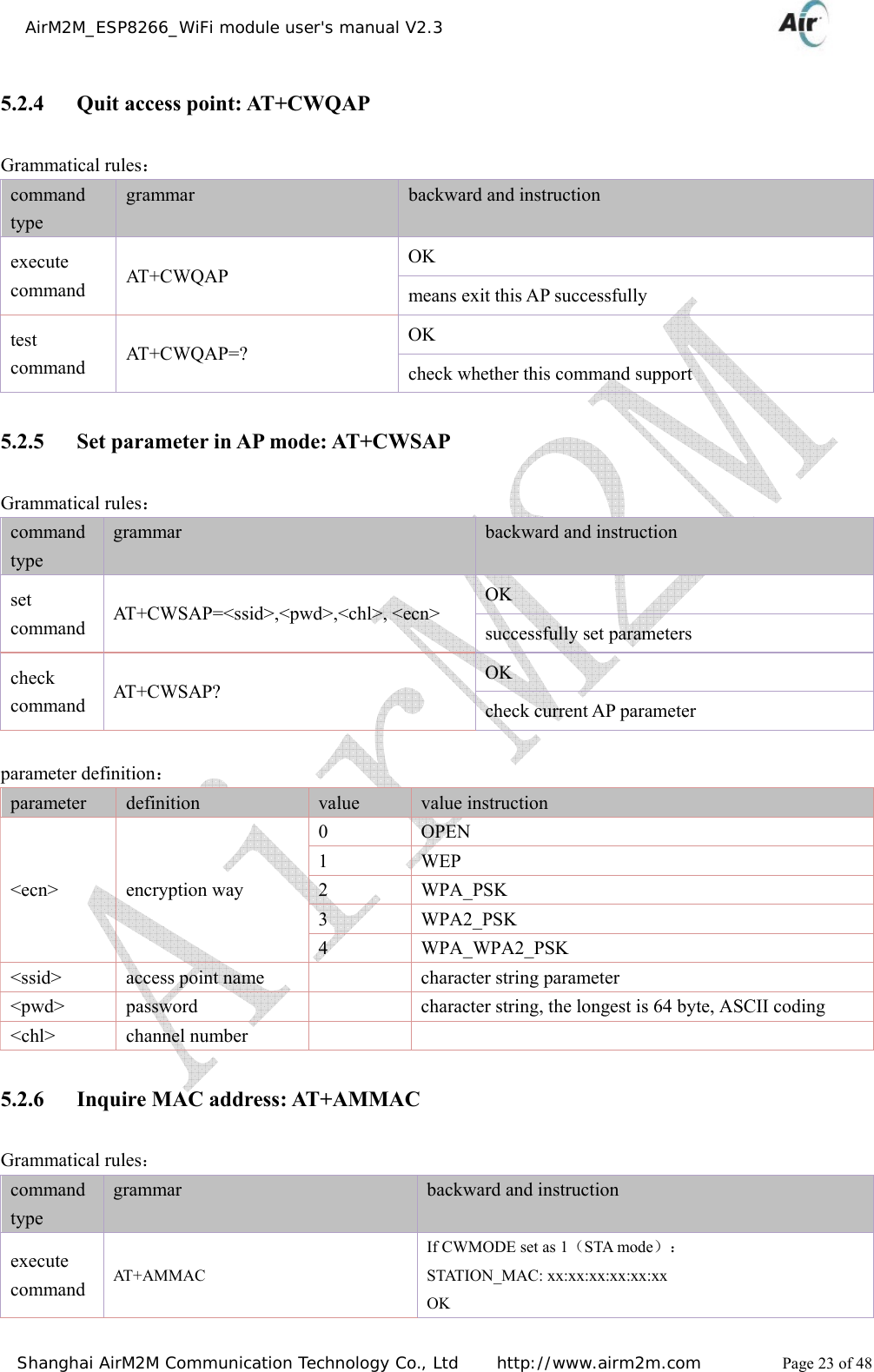
![AirM2M_ESP8266_WiFi module user's manual V2.3 Shanghai AirM2M Communication Technology Co., Ltd http://www.airm2m.com Page 31 of 48 5.3.6 Obtain local IP address:AT+CIFSR Grammatical rules: command type grammar Response and instruction Execute command AT+CIFSR response + CIFSR:<IP address> OK or ERROR test command AT+CIFSR=? response OK parameter definition: parameter definition value value instruction <IP address> Local current IP address(station) 5.3.7 Configure as server:AT+CIPSERVER Grammatical rules: command type grammar Response and instruction instruction Need execute AT+CIPMUX=1 first, turn on mux mode. To monitor 2 ports at most, including TCP and UDP. Execute command AT+CIPSERVER=<mode>[,<port>] response After start server, it will automatically set up monitor by server. OK If there is client connect to the server of this module then it will go back to : <linkid>,CONNECT OK If number 0 connection is occupied then it goes back to +CME ERROR: no change Note: Need reboot if use AT+CIPSERVER=0 to shut down server. parameter definition: parameter definition value value instruction <mode> whether turn on server mode 0 turn off server mode 1 turn on server mode <port> port number default value is 333](https://usermanual.wiki/AirM2M-Communication-Technology/A6501/User-Guide-2583778-Page-31.png)