AirVast Technology AB015WR2000 802.11b WLAN Router User Manual
AirVast Technology Inc. 802.11b WLAN Router Users Manual
UserManual.wiki
>
AirVast Technology
>
AB015WR2000 User Manual
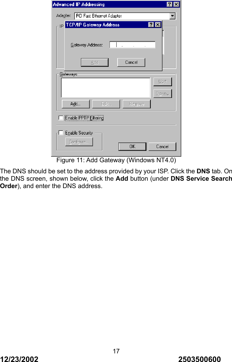
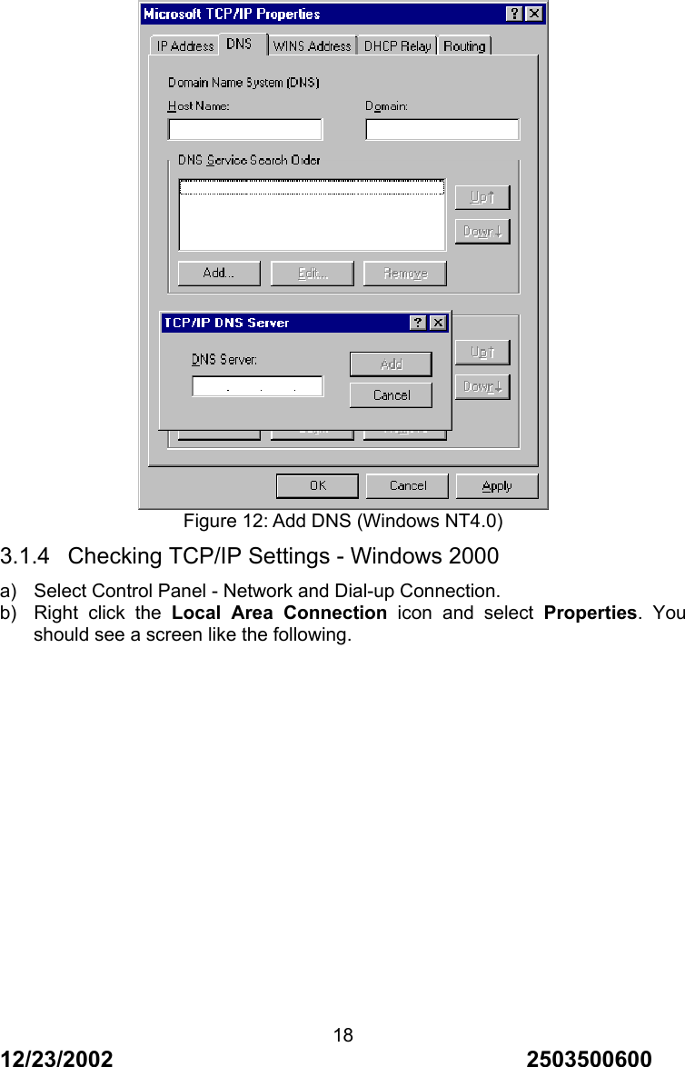
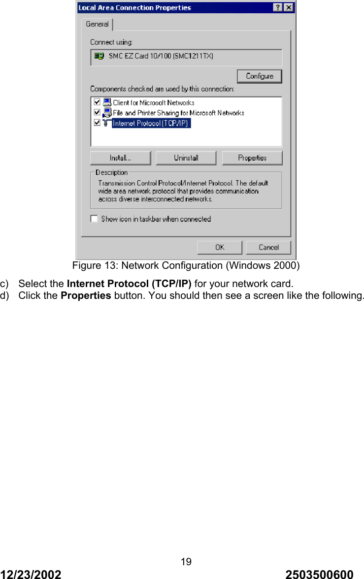
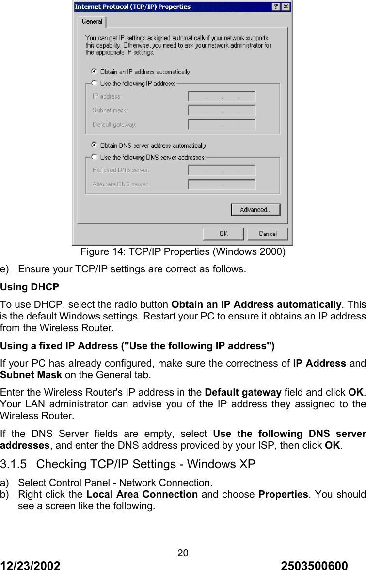
Users Manual
Navigation menu
Upload a User Manual
Namespaces
Wiki Guide
HTML
PDF
Info
Views
User Manual
Discussion / Help
Navigation