AirVast Technology AB025WA1300 802.11b WLAN Access Point User Manual AP draft
AirVast Technology Inc. 802.11b WLAN Access Point AP draft
User Manual
8
8
80
0
02
2
2.
.
.1
1
11
1
1b
b
b
W
W
WL
L
LA
A
AN
N
N
A
A
Ac
c
cc
c
ce
e
es
s
ss
s
s
P
P
Po
o
oi
i
in
n
nt
t
t
User Manual
2
No part of this documentation may be reproduced in any form or by any means or used to make any
derivative work (such as translation, transformation, or adaptation) without written permission from
the copyright owner.
All the other trademarks and registered trademarks are the property of their respective owners.
Statement of Conditions
We may make improvements or changes in the product described in this documentation at any
time. The information regarding to the product in this manual are subject to change without notice.
We assumes no responsibility for errors contained herein or for direct, indirect, special, incidental, or
consequential damages with the furnishing, performance, or use of this manual or equipment
supplied with it, even if the suppliers have been advised of the possibility of such damages.
Electronic Emission Notices
This device complies with Part 15 of the FCC Rules. Operation is subject to the following two
conditions:
(1)This device may not cause harmful interference.
(2)This device must accept any interference received, including interference that may cause
undesired operation.
FCC INFORMATION
The Federal Communication Commission Radio Frequency Interference Statement includes the
following paragraph:
The equipment has been tested and found to comply with the limits for a Class B Digital Device,
pursuant to part 15 of the FCC Rules. These limits are designed to provide reasonable protection
against harmful interference in a residential installation. This equipment generates, uses and can
radiate radio frequency energy and, if not installed and used in accordance with the instruction, may
cause harmful interference to radio communication. However, there is no grantee that interference
will not occur in a particular installation. If this equipment dose cause harmful interference to radio or
television reception, which can be determined by turning the equipment off and on, the user is
encouraged to try to correct the interference by one or more of the following measures:
--Reorient or relocate the receiving antenna.
--Increase the separation between the equipment and receiver.
--Connect the equipment into an outlet on a circuit different from that to which the receiver is
connected.
--Consult the dealer or an experienced radio/TV technician for help.
The equipment is for home or office use.
IMPORTANT NOTE
FCC RF Radiation Exposure Statement: This equipment complies with FCC RF radiation exposure
limits set forth for an uncontrolled environment. This equipment should be installed and operated
with a minimum distance of 20cm between the antenna and your body and must not be co-located
or operating in conjunction with any other antenna or transmitter.
3
Caution: Changes or modifications not expressly approved by the party responsible for
compliance could void the user's authority to operate the equipment.

4
Table of Contents
Introduction ....................................................................................................................6
1.1 Features................................................................................................6
1.2 Specifications.......................................................................................6
1.3 Product Kit............................................................................................8
1.4 System Requirements.........................................................................9
Getting to Know 802.11b WLAN Access Point................................................................9
2.1 Ports......................................................................................................9
2.2 LEDs....................................................................................................10
2.3 Installation..........................................................................................11
Preparation for Installation...................................................................................11
Hardware Installation ..........................................................................................11
Configuring Windows for IP Networking....................................................................... 12
If you are using Windows 98/Me: ........................................................................ 12
If you are using Windows 2000: .......................................................................... 13
If you are using Windows XP:............................................................................. 14
Utilizing the WLAN Access Point .................................................................................. 16
Overview of the Interface...................................................................................16
The Info Tab...................................................................................................... 17
The Assoc Tab................................................................................................... 17
The Configuration Tab........................................................................................ 18
The MAC Filter Tab............................................................................................ 19
The Advanced Tab............................................................................................. 20
The Encryption Tab............................................................................................ 21
The Admin Tab.................................................................................................. 22
5
The Help Tab..................................................................................................... 23

6
Introduction
The 802.11b WLAN Access Point card aims to assist you in easily building a communicable
connection between your wired LAN and one or more Wireless Local Area Networks. It’s easy
to install and operate. To let you enjoy the most advantages of this product, please read this
manual carefully.
1.1 Features
802.11b Wi-Fi compliant
Quick and easy to install
Works with any device that has an Ethernet port
LED indicators show unit operating status
FCC Certified for use with YDI amplifiers and outdoor antennas with the Diamond WLAN
Card
Web-based configuration screen of Access Point enables fast and easy setup
Supports RTS threshold control for better throughput
Wireless data encryption with 64 and 128 bits encryption for security
One-year warranty
1.2 Specifications
Data Rates Supported 1, 2, 5.5, and 11 Mbps
Network Standard IEEE 802.11b
Uplink 10BaseT Ethernet
Frequency Band 2.4 to 2.497 GHz (subject to local regulations)
Network Architecture Types Infrastructure

7
Wireless Medium Direct Sequence Spread Spectrum (DSSS)
Media Access Protocol Carrier sense multiple access with collision avoidance (CSMA/CA)
Modulation DBPSK @1 Mbps; DQPSK @ 2 Mbps; CCK @ 5.5 and 11 Mbps
Operating Channels (US/FCC: 1-11, Europe/ETSI: 1-13)
Non-overlapping Channels Three
Receive Sensitivity 1 Mbps: –94 dBm
2 Mbps: –91 dBm
5.5 Mbps: –87 dBm
11 Mbps: –83 dBm
Available Transmit Power
Settings
99 mW
Range
(typical @ 99-mW transmit
power setting, including 1.95 dBi
diversity dipole antenna)
Indoor:
165 ft (50 m) @ 11 Mbps
350 ft (107 m) @ 1 Mbps
Outdoor:
800 ft (244 m) @ 11 Mbps
2000 ft (610 m) @ 1 Mbps
EMC Certification FCC 47CFR15 subpart C (15.247) and Class B device
ETSI 300-328/301-489-17 (General EMC requirement for RF
equipment)
Antenna Two soldered dipole antennas
Encryption Key Length 64-bit, 128-bit

8
Security IEEE 802.11 WEP (Wired Equivalent Privacy)
Filter MAC Address Filtering
Status Indicators Three indicators on the top panel provide status of POWER
Wireless LAN
Automatic Configuration Support
DHCP client
Remote Configuration Support HTTP, TFTP
Dimensions 6.30 in. (16 cm) wide x 4.72 in. (12 cm) deep x 1.45 in. (3.7 cm)
high
Weight 12.3 oz (350g)
Environmental Operating temperature: 0℃ to 40℃ (32℉ to 104℉)
Storage temperature: -20℃ to 70℃ (-4℉ to 158℉)
Humidity: 10 to 90% (non-condensing)
Input Power Requirements DC 5V 2A
Warranty One year
1.3 Product Kit
The Access Point Kit contains the following items:
ü One 802.11b WLAN Access Point
ü One Power Adapter
ü One Quick Installation Guide
ü One User Manual
ü One RJ45 Ethernet Straight LAN cable
9
Set to Default Button
Note: If any item listed above is damaged or missing, please contact your dealer immediately.
1.4 System Requirements
To accomplish a successful operation of your 802.11b WLAN Access Point, we suggest the
following items are required:
ü One or more PCs (desktop or notebook) with Ethernet interface.
ü TCP/IP protocol must be installed on all PCs.
ü Network cables. Use standard 10/100BaseT network (UTP) cables with RJ45
connectors.
ü To use the Wireless Access Point, all wireless devices must be compliant with the IEEE
802.11b specifications.
ü Microsoft Internet Explorer 5.0 or later or Netscape Navigator 4.7 or later.
Getting to Know 802.11b WLAN Access Point
This section is consisted of three parts. You will learn the guise of the hardware, including the
ports and LEDs, and the installation of Access Point.
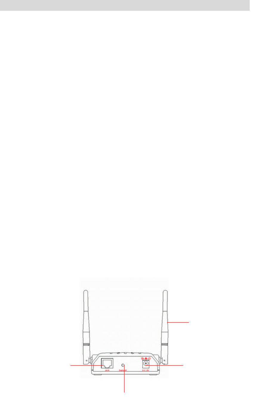
2.1 Ports
The 802.11b WLAN Access Point’s Ports are on the rear panel of the device. Please see the
following picture – the rear view of the Access Point to learn more details about your device.
Antenna Connection
LAN Connection
DC 5V Power Input
10
Antenna Connection Install the dipole antenna directly into the reversed SMA connector
of AP. After the Access Point begins to work, you may adjust the
angle of the antenna or reposition your Access Point to obtain a
better performance.
LAN Connection Use RJ-45 Ethernet straight LAN cable to connect your PC,
hub/switch or broadband router/modem to this port.
DC 5V Power Input Use the power adapter which is only supplied with your Access
Point.
Set to Default Button When you press this button, the Access Point will reboot and reset
current settings to factory default settings.
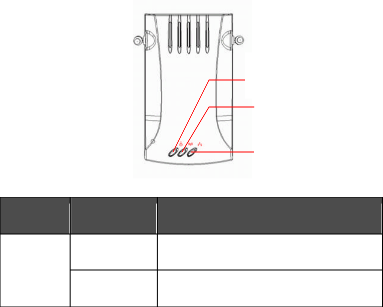
2.2 LEDs
The 802.11b WLAN Access Point includes three types of LED indicators. Please check the
following picture – the front view of the Access Point and table to obtain the information on the
LED indicators on your Access Point.
LED Status Function
On Power on.
Power
Off No power.
Wired
Wireless LAN
Power

11
LED Status Function
Wireless LAN
Blinking
On
Off
Blinking: Wireless LAN is transmitting.
On: Wireless LAN connection is active.
Off: Wireless LAN connection is not active.
Wired Blinking
On
Off
Blinking: Wired LAN is transmitting.
On: Wired LAN is active.
Off: Wired LAN is not active.
2.3 Installation
Preparation for Installation
Before you actually install your 802.11b WLAN Access Point, please ensure that all the items
listed in “1.4 System Requirements” are prepared, and then choose the place with the
consideration of power outlet and network connection to install the Access Point.
To avoid causing any damage to the Access Point hardware device, please do not power up
the device before you start to connect it to the port on your PC.
Also notice that a full installation of your Access Point includes not only the hardware
installation but also the network configuration on your PC. Check the following section
-“Hardware Installation” and the next chapter - “Configuring Windows for IP Networking” to
obtain complete details.
Hardware Installation
Follow the procedures below to fully install your Access Point hardware device:
1. Select a suitable place on the network to install the Access Point. Ensure the Access
Point and the DSL/cable modem are powered off. For best wireless reception and
performance, the Access Point should be positioned in a central location with minimum
obstructions between the Access Point and the PCs.
2. Connect one end of Ethernet cable to Access Point and the other to switch or hub, and
then the Access Point will be connected to the 10/100 Network.
12
3. Connect the power adapter to the power socket on your Access Point.
4. Last but not the least, check the LEDs on the Access Point to confirm if the status is okay.
5. Now the hardware installation is complete, and you may proceed to the next
chapter –“ Configuring Windows for IP Networking” for instruction on setting up network
configurations.
Configuring Windows for IP Networking
To establish a communication between your PCs and the 802.11b WLAN Access Point, you
will need an IP address for your computer first. This section helps you configure the network
settings for your operating system. Please follow the procedures below to complete the
settings:
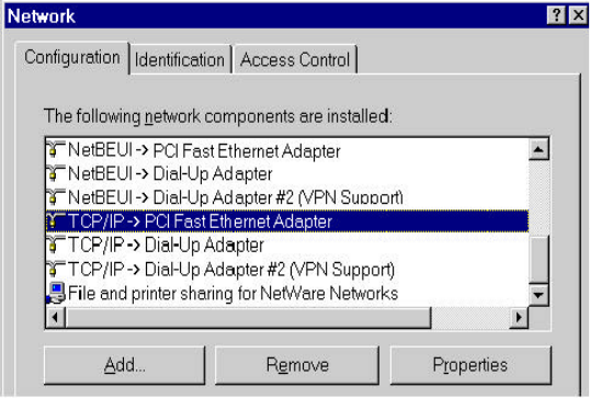
If you are using Windows 98/Me:
1. Click Start on the taskbar and choose Control Panel from the submenu of Settings.
2. Select Network to open the Network dialog box, and then under the Configuration tab,
select the TCP/IP protocol for your network card.
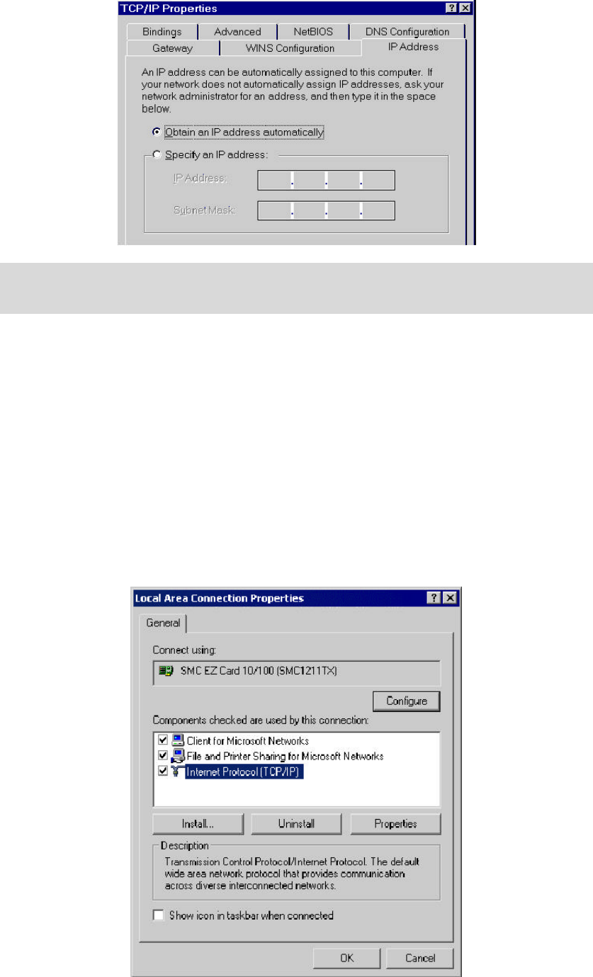
3. Click Properties to open the TCP/IP Properties dialog box.
4. Click the IP Address tab and choose Specify an IP address. Type 192.168.1.200 in the
IP Address area and 255.255.255.0 in the Subnet Mask area. To ensure the system is
now using the IP address you specify, restart your computer to check later.
13
Note: The IP address must be 192.168.1.x. The value of X should be ranged from 1 to 254
and is never used by other PCs.
5. Click OK, and then restart the system.
If you are using Windows 2000:
1. Click Start on the taskbar and choose Network and Dial-up Connection from the
submenu of Settings.
2. Double-click the Local Area Connection open the Local Area Connection Properties
box.
14
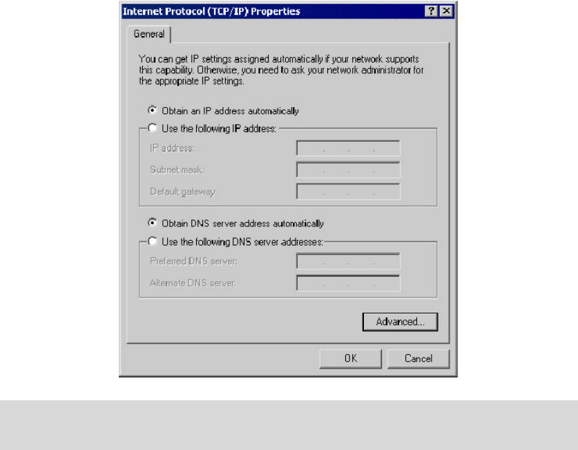
3. Select the Internet Protocol (TCP/IP) for your network card, and then click Properties
to open the Internet Protocol (TCP/IP) Properties dialog box.
4. Under the General tab, choose Use the following IP address, and then enter
192.168.1.200 in the IP Address area and 255.255.255.0 in the Subnet Mask area.
Note: The IP address must be 192.168.1.x. The value of X should be ranged from 1 to 254
and is never used by other PCs.
5. Click OK, and then restart the system.
If you are using Windows XP:
1. Click Start on the taskbar and choose Network from the submenu of Control Panel.
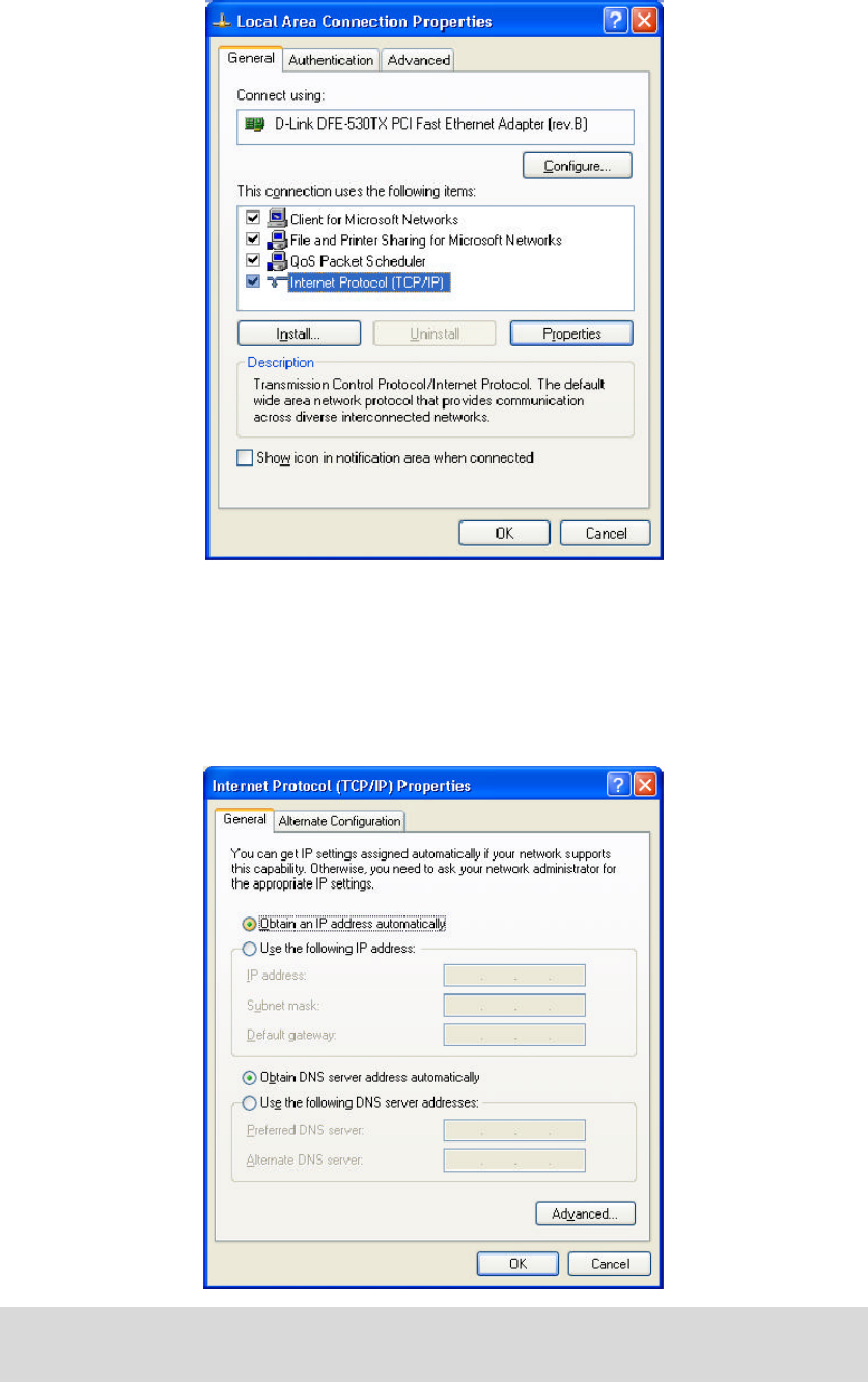
2. Right-click the Local Area Connection icon and then choose Properties from the menu.
You should see the Local Area Connection Properties dialog box shown below.
15
3. Select the Internet Protocol (TCP/IP) for your network card, and then click Properties.
4. In the opened dialog box, choose Use the following IP address under the General tab,
enter 192.168.1.200 in the IP Address area and 255.255.255.0 in the Subnet Mask
area.
Note: The IP address must be 192.168.1.x. The value of X should be ranged from 1 to 254
and is never used by other PCs.
5. Click OK, and then restart the system.
16
Utilizing the WLAN Access Point
Overview of the Interface
The 802.11b Access Point’s Web-based Configuration utility presents a user-friendly interface,
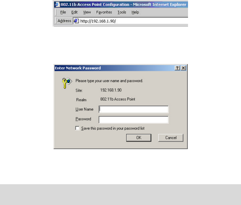
so that you can easily execute the program by following the on-screen explanations. Type
HTTP://192.168.1.90 in the Address box after opening your Web browser.
Then press Enter on your keyboard, you will see the Enter Network Password dialog box
appear like the picture below shows.
The default User Name and Password is nil. Leave User Name and Password field blank
and then click OK.
Note: You may set a new password by clicking the Admin tab after you enter the 802.11b
Access Point Configuration Web page.
Later, you will see eight tabs in the main interface of Access Point Configuration, including
Info, Assoc, Configuration, MAC Filter, Advanced, Encryption, Admin, and Help, and
each of them provides different settings. Check the section below for more information on
them.
17
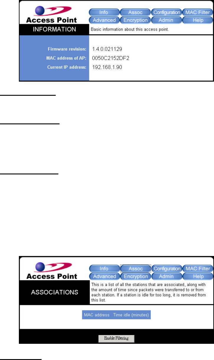
The Info Tab
Click this tab to display simple information on the selected Access Point, including Firmware
revision, Mac address of AP, and Current IP address.
Firmware revision
Here displays the present version of the Access Point’s firmware.
MAC address of AP
The MAC (Media Access Control) address of AP is the number of your computer's unique
hardware - your NIC (Network interface card). It is consisted of 12-digit hexadecimal
numbers (48 bits in length) to identify your computer's physical address on the LAN.
Current IP address
In this field, enter the IP address to assign to the access point. Notice that the address
should be on the same subnet as the device to which you connect the access point.
The Assoc Tab
On the Associations tab, all the wireless clients currently associating with your AP are listed
here
MAC address
18
Here displays the MAC addresses of all the associated wireless clients.
Time idle
When any client is idle, this field will display the idle time of it.
Enable Filtering
Click to activate the function of filtering.
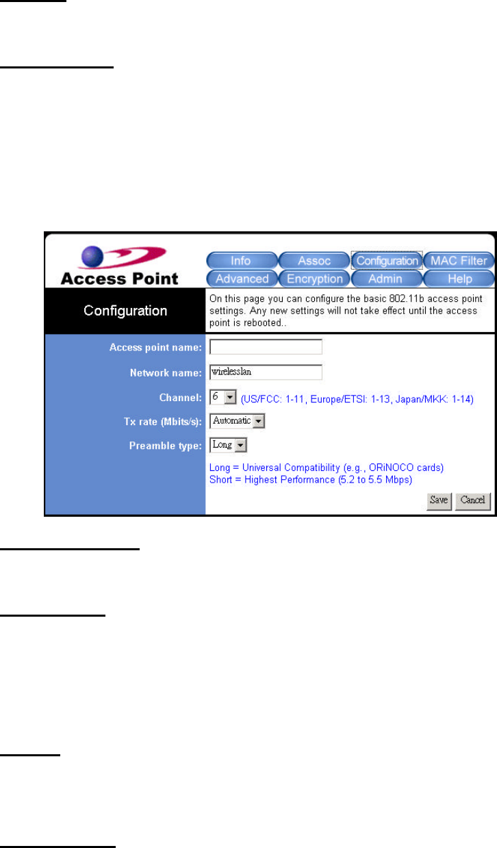
The Configuration Tab
This tab offers basics settings of your wireless network. When you are done, click Save and
then Reboot to activate the new configurations.
Access Point Name
Set your Access Point alias name in this box.
Network Name
Decide what your network name will be named here, therefore, the client stations can freely
roam over the Access Point as long as they know the Network Name, the identifier of your
WLAN. Network Name is also known as SSID, which stands for Service Set Identifier. Any
client has to indicate the SSID of the intended Access Point to start accessing.
Channel
Set the channel number to be used from the list provided. Note that the available channels
differ from country to country.
Tx rate (Mbits/s)
This option indicates the transmission rate at which clients of the AP transfer the data packet.
19
Specify the rate according to the speed of your wireless network from the list.
Preamble type
Define the Preamble type as Long or Short. The Short preamble option presents a better
throughput performance; however, this depends upon the supportiveness of your wireless
LAN card.
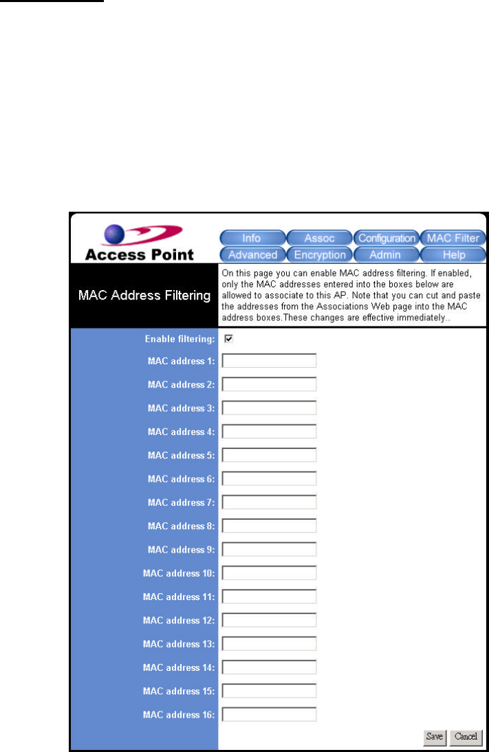
The MAC Filter Tab
This tab helps you to allow or oppose the access of certain computers by recognizing their
MAC Addresses.
In the MAC Address Filtering area, tick on the Enable filtering option to filter the access.
Then edit the list below in the MAC address 1-16 fields by entering the MAC Addresses that
you consent the access. When done, click the Save button and then the Reboot button to
complete the settings.
20
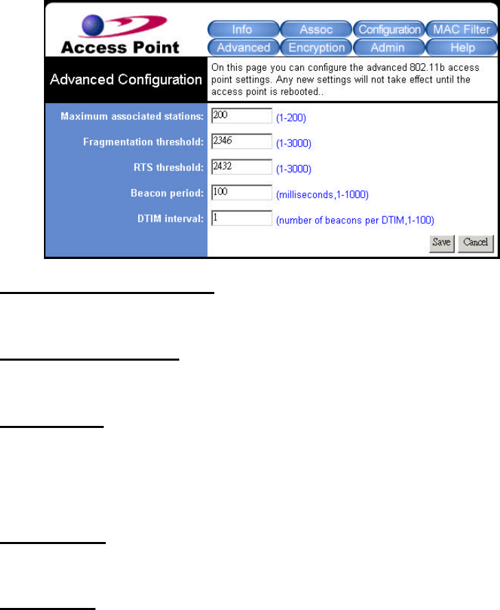
The Advanced Tab
To specify more advanced settings for your WLAN network, click this tab to open the
Advanced Configuration page. However, before you start making any new configuration here,
please check your other systems, since any changes to these settings may influence the
effectiveness of some relative network performance. Therefore, leave these settings as default
status unless there’s any special demand.
Maximum associated stations
Define the maximum number of the associated stations regarding the load balance.
Fragmentation threshold
Specify the size at which data packets will be fragmented.
RTS threshold
Set the minimum packet size that requires a RTS (Request to Send) to be transmitted. In
other words, packets that are smaller than this threshold could be transfer directly to the
WLAN.
Beacon period
Set a value here to define the duration between beacon packets.
DTIM interval
Set a value in the DTIM (Delivery Traffic Indication Message) interval box to define how
often the beacon contains a delivery traffic indication message.
When done, click Save and Reboot to complete.
21
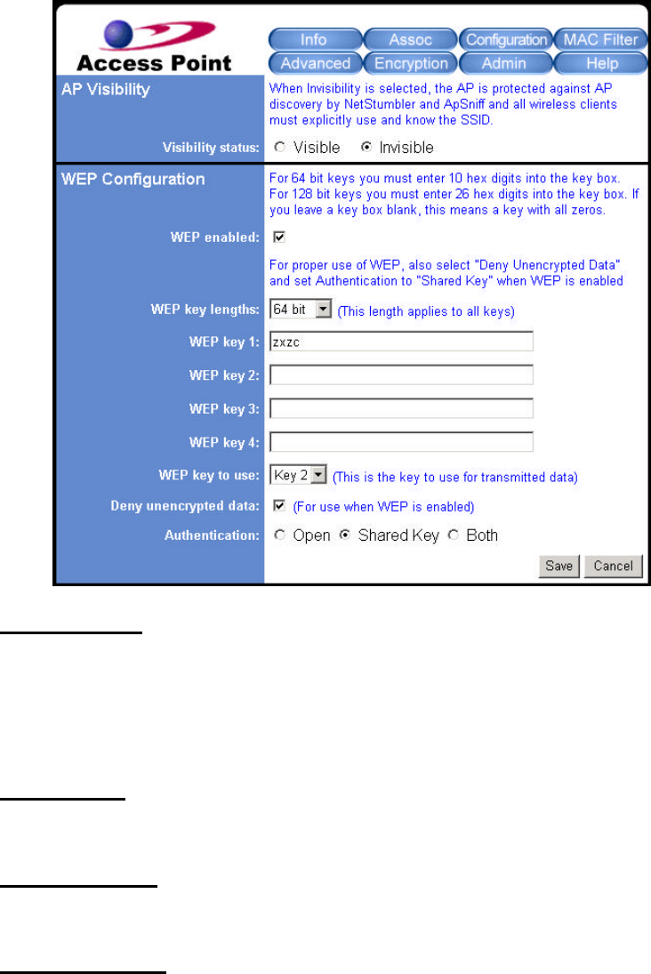
The Encryption Tab
The Encryption tab offers you various options to maintain the secure management in a
wireless LAN environment. See the explanations below for more details, and before making an
activation of any new settings, click Save and then Reboot.
Visibility status
This option determines your AP Visibility to be Visible or Invisible.
In the WEP (Wired Equivalent Privacy) Configuration area, you are allowed to put more
advanced settings to establish a data privacy mechanism.
WEP enabled
Tick on the box to enable all the WEP configurations below.
WEP key lengths
Two key lengths are offered: 64 bits and 128 bits in the pull-down list.
WEP Key 1, 2, 3, 4
Edit the texts in the blank fields as the encryption codes, and these codes/keys shall be
identical between the stations and the Access Point only.
22
WEP key to use
Indicate which WEP key you intend to apply to activate the WEP encryption. Make sure that
each point on the wireless network shares the same keys.
Deny unencrypted data
Enable this function to deny any request that is not encrypted.
Authentication
Three Authentication types are provided: Open, Shared Key, and Both. The Open option
allows any station in the WLAN to associate with the Access Point and receive and transmit
data. The Shared Key allows only the stations that use identified keys to associate with the
Access Point. While choosing Both, any station can associate with the Access Point either
with or without encryption keys.
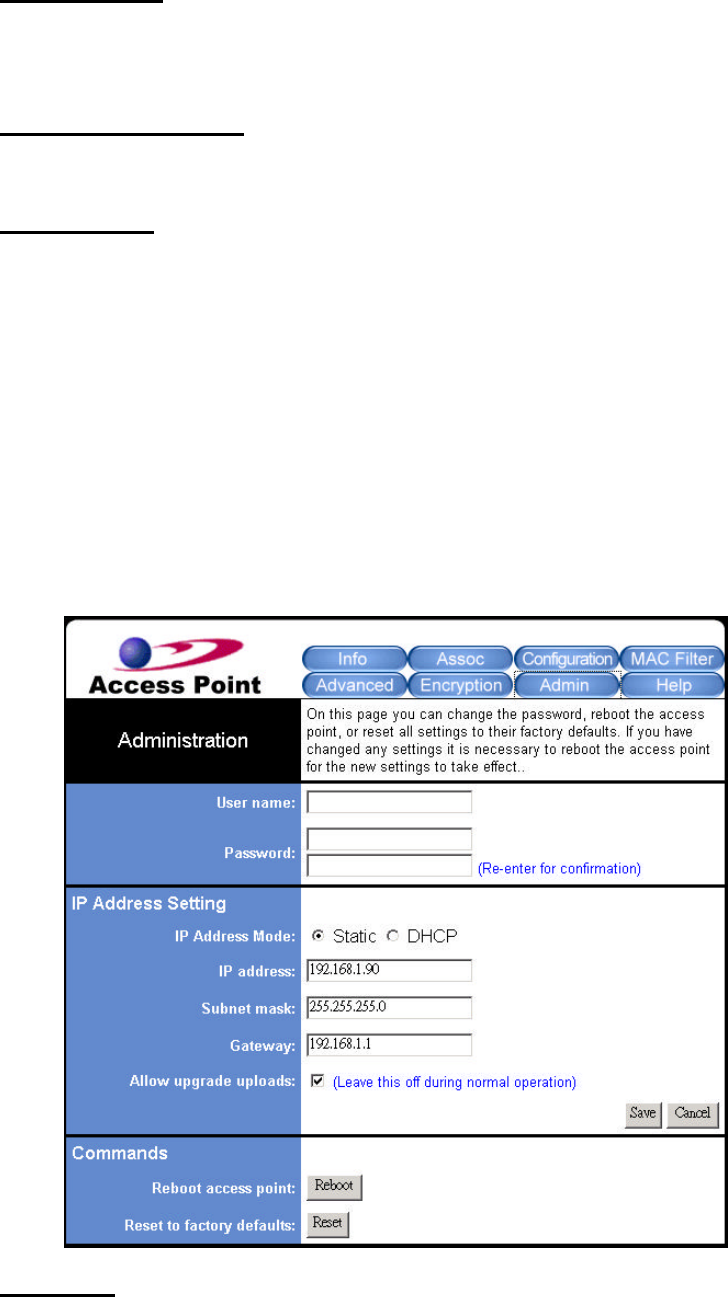
The Admin Tab
Once you click on the Administration tab, you may assign a new name, password, TCP/IP
network settings, etc. for your Access Point.
User Name
Enter any name you want to use in the blank field.

23
Password
Enter the new password in the upper blank field. And re-enter it again in the blank field
below to make a confirmation.
In the IP Address Setting area, you can verify the current IP settings. Remember to click
Save and Reboot after you finish off.
IP Address Mode
Define your IP Address Mode as Static or DHCP.
IP address
Verify your IP address here if there’s a need.
Subnet mask
Specify the subnet mask you want to assign for the AP here.
Gateway
Enter the gateway IP you want to assign for the AP here if it is required.
Allow upgrade uploads
Enable this option to allow the upgrading of firmware.
The Commands area offers two options for you to change the device’s system settings.
Reboot access point
Click Reboot to let the AP be rebooted immediately and confirm all the changes.
Reset to factory defaults
Click Reset to remove all the current settings and go back to the factory defaults.
The Help Tab
Click to look for more details regarding this program.