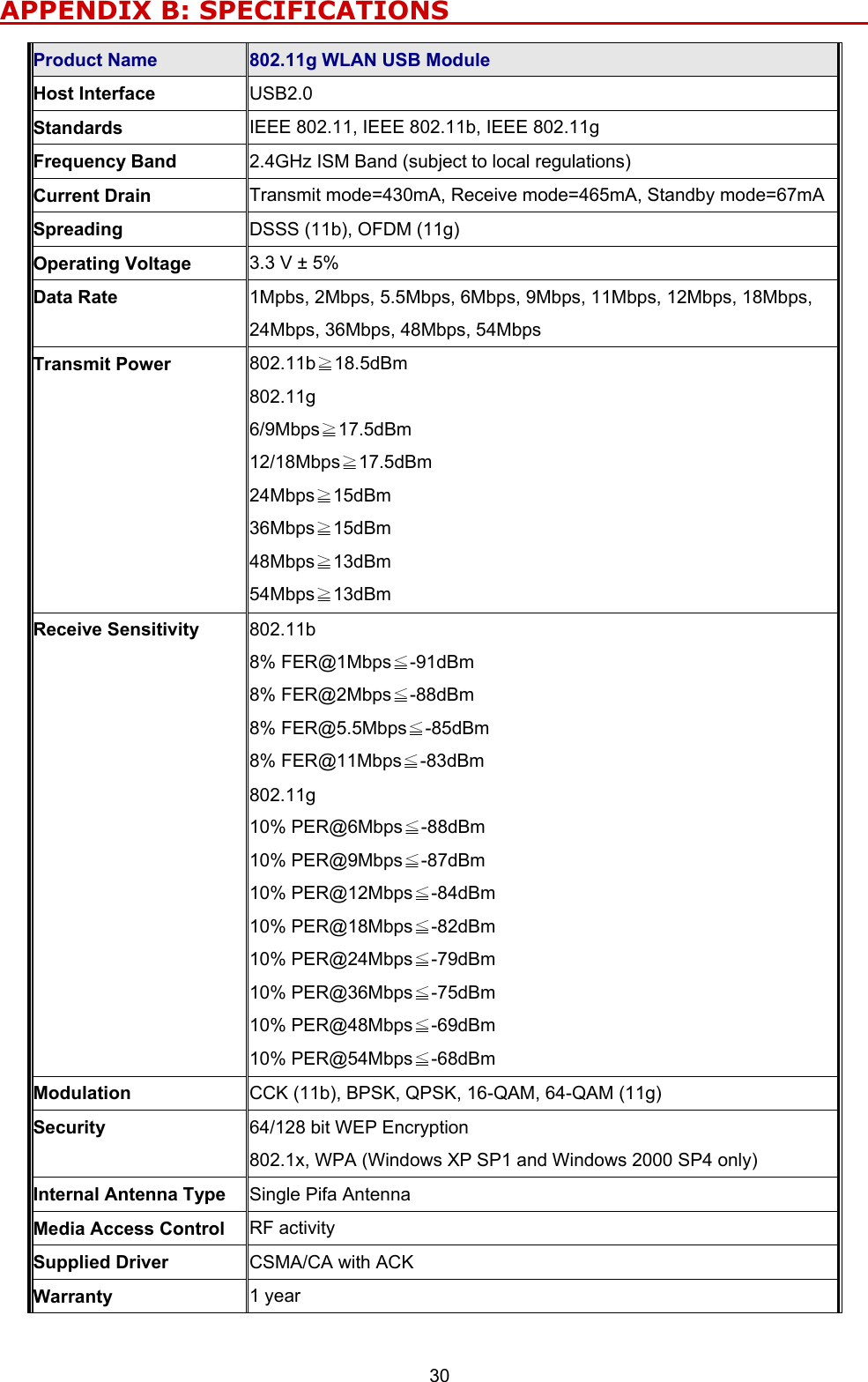
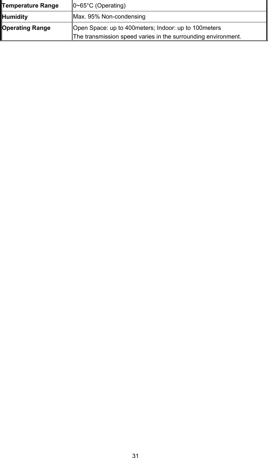
AirVast Technology WM168GC 802.11g WLAN USB Module User Manual

AirVast Technology Inc. 802.11g WLAN USB Module

Contents

User manual

           880022..1111gg  WWLLAANN  UUSSBB  MMoodduullee               WM-168gc OEM Reference Installation Guide Version 1.2
 1
 2 No part of this documentation may be reproduced in any form or by any means or used to make any derivative work (such as translation, transformation, or adaptation) without written permission from the copyright owner. All the other trademarks and registered trademarks are the property of their respective owners. Statement of Conditions We may make improvements or changes in the product described in this documentation at any time. The information regarding to the product in this manual are subject to change without notice. We assume no responsibility for errors contained herein or for direct, indirect, special, incidental, or consequential damages with the furnishing, performance, or use of this manual or equipment supplied with it, even if the suppliers have been advised of the possibility of such damages. Electronic Emission Notices This device complies with Part 15 of the FCC Rules. Operation is subject to the following two conditions: (1) This device may not cause harmful interference. (2) This device must accept any interference received, including interference that may cause undesired operation. FCC INFORMATION The Federal Communication Commission Radio Frequency Interference Statement includes the following paragraph: The equipment has been tested and found to comply with the limits for a Class B Digital Device, pursuant to part 15 of the FCC Rules. These limits are designed to provide reasonable protection against harmful interference in a residential installation. This equipment generates, uses and can radiate radio frequency energy and, if not installed and used in accordance with the instruction, may cause harmful interference to radio communication. However, there is no guarantee that interference will not occur in a particular installation. If this equipment does cause harmful interference to radio or television reception, which can be determined by turning the equipment off and on, the user is encouraged to try to overcome the interference by one or more of the following measures: --Reorient or relocate the receiving antenna. --Increase the separation between the equipment and receiver. --Connect the equipment into an outlet on a circuit different from that to which the receiver is connected. --Consult the dealer or an experienced radio/TV technician for help. The equipment is for home or office use. IMPORTANT NOTE FCC RF Radiation Exposure Statement: This equipment complies with FCC RF radiation exposure limits set forth for an uncontrolled environment. This equipment should be installed and operated with a minimum distance of 20cm between the antenna and your body and must not be co-located or operating in conjunction with any other antenna or transmitter.  Caution: Changes or modifications not expressly approved by the party responsible for compliance could void the user's authority to operate the equipment.
 3 R&TTE Compliance Statement This equipment complies with all the requirements of the Directive 1999/5/EC of the European Parliament and the Council of 9 March 1999 on radio equipment and telecommunication terminal equipment (R&TTE)and the mutual recognition of their conformity. The R&TTE Directive repeals and replaces in the directive 98/13/EEC. As of April 8, 2000. European Union CE Marking and Compliance Notices Products intended for sale within the European Union are marked, which indicates compliance with the applicable directives identified below. This equipment also carries the Class 2 identifier. with the Conformité Européene (CE) and European standards and amendments. We declares that the equipment described in this document is in conformance with the essential requirements of the European Council Directives, standards, and other normative documents listed below: 73/23/EEC Safety of the User (article 3.1.a) 89/336/EEC Electromagnetic Compatibility (article 3.1.b) 1999/5/EC (R&TTE) Radio and Telecommunications Terminal Equipment Directive.  EN 60950 2000 Safety of Information Technology Equipment, Including Electrical Business Equipment.  EN 300 328 V1.2.1(2001) Electromagnetic compatibility and Radio spectrum Matters (ERM); Wideband Transmission systems;Data transmission equipment operatingin the 2,4 GHz ISM band and using spread spectrum modulation techniques;Harmonized EN covering essential requirements under article 3.2 of the R&TTE Directive.  EN 301 489-1, V1.2.1(2002); EN 301489-17, V1.2.1(2002) – Electromagnetic compatibility and radio spectrum matters (ERM); electromagnetic compatibility (EMC) standard for radio equipment and services: Part 1: Common technical requirements; Part 17: Part 17: Specific conditions for 2,4 GHz wideband transmission systems and5 GHz high performance RLAN equipment  Warning: According to ERC/REC 70-30 appendix 3 National Restrictions, annex 3 Band A “RLANs and HIPERLANs.” See list of 802.11b/g restrictions for specific countries under the heading “European Economic Area Restrictions” as below.  English This product follows the provisions of the European Directive 1999/5/EC. Danish Dette produkt er i overensstemmelse med det europæiske direktiv 1999/5/EF Dutch Dit product is in navolging van de bepalingen van Europees Directief 1999/5/EC. Finnish Tämä tuote noudattaa EU-direktiivin 1999/5/EY määräyksiä. French Ce produit est conforme aux exigences de la Directive Européenne 1999/5/CE. German Dieses Produkt entspricht den Bestimmungen der Europäischen Richtlinie 1999/5/EG. Greek  Icelandic Þessi vara stenst reglugerð Evrópska Efnahags Bandalagsins númer 1999/5/EC. EK.
 4 Italian Questo prodotto è conforme alla Direttiva Europea 1999/5/EC. Norwegian Dette produktet er i henhold til bestemmelsene i det europeiske direktivet 1999/5/CE. Portuguese Este produto cumpre com as normas da Diretiva Européia 1999/5/CE. Spanish Este producto cumple con las normas del Directivo Europeo 1999/5/CE. Swedish Denna produkt har tillverkats i enlighet med EG-direktiv 1999/ 5/EG.   European Economic Area Restrictions  LOCAL RESTRICTION OF 802.11B/G RADIO USAGE We follow and are acknowledged of relevant ECC/ERC decisions, recommendations, and ETSI standards as below: ERC/DEC(01)07 Radio-Lan Short Range Devices in 2400-2483.5MHz.  802.11B/G RESTRICTIONS European standards dictate maximum radiated transmit power of 100mW EIRP and frequency range 2.400 – 2.4835 GHz.   France Outdoor use limited to 10 mW e.i.r.p. within the band 2454-2483.5 MHz Romania  On a secondary basis. Individual license required. T/R 22-06 not implemented
 5 TTaabbllee  ooff  CCoonntteennttss  INTRODUCTION ...........................................................................................................................................1 1.1 Features.................................................................................................................................. 1 1.2 Package Contents .................................................................................................................. 1 1.3 System Requirements ............................................................................................................ 1 INSTALLATION OF WIRELESS 802.11G/B USB MODULE ..................................................................3 2.1 Installation Procedures ........................................................................................................... 3 Confirm the Existence of the Module........................................................................................................3 Installation Procedures.............................................................................................................................3 2.2 Installation Notes - Windows XP.............................................................................................6 2.3 Verifying a Successful Installation .......................................................................................... 8 WLAN-54G USB CONFIGURATION TOOL BASICS ............................................................................10 3.1 Tray Icon ............................................................................................................................... 10 3.2 Right-Click Menu of the Tray Icon......................................................................................... 10 Wireless Radio On .................................................................................................................................. 11 Wireless Radio Off .................................................................................................................................. 11 Remove Status Icon................................................................................................................................. 11 Wireless Network Status.......................................................................................................................... 11 Advanced Configuration......................................................................................................................... 11 WEP Encryption ..................................................................................................................................... 11 IBSS Channel..........................................................................................................................................11 Country/Domain .................................................................................................錯誤! 尚未定義書籤。 Version Information ................................................................................................................................ 11 3.3 Configuration Tool Basics ..................................................................................................... 12 The Status Tab.........................................................................................................................................12 State....................................................................................................................................................13 Current Tx Rate ..................................................................................................................................14 Current Channel .................................................................................................................................14 Throughput (bytes/sec).......................................................................................................................14 Link Quality .......................................................................................................................................14 Signal Strength ...................................................................................................................................14 The Configuration Tab............................................................................................................................14 Profile Name ......................................................................................................................................15 Network Name ...................................................................................................................................15 Network Type .....................................................................................................................................15 Peer-to-Peer Channel..........................................................................................................................16 Transmit Rate .....................................................................................................................................16 The Encryption Tab.................................................................................................................................16
 6 Encryption (WEP security).................................................................................................................17 Create Keys Manually........................................................................................................................17 Use WEP Key.....................................................................................................................................17 Create Keys with Passphrase..............................................................................................................18 The Site Survey Tab.................................................................................................................................18 The IBSS Tab...........................................................................................................................................18 The About Tab.........................................................................................................................................19 Network Driver ..................................................................................................................................19 Configuration Utility ..........................................................................................................................19 NIC Firmware ....................................................................................................................................20 3.4 The Advanced Properties Tab............................................................................................... 20 Authentication TYPE .........................................................................................................................21 Configuration Profile..........................................................................................................................21 Nitro Mode .........................................................................................................................................22 Power Save Mode...............................................................................................................................22 WINDOWS XP WIRELESS ZERO CONFIGURATION TOOL ............................................................23 4.1 To Connect an Available Network via Wireless Zero Configuration ...................................... 23 4.2 To Configure the Wireless Networks Properties ................................................................... 23 4.3 To Access to Certain Wireless Network Type ....................................................................... 26 APPENDIX A: TROUBLESHOOTING .....................................................................................................28 The Wireless 802.11g/b USB Module Does Not Work Properly ................................................. 28 Disable the Wireless 802.11g/b USB Module ............................................................................. 28 Uninstall WLAN-54G USB Configuration Tool and the Module’s Driver ..................................... 28 APPENDIX B: SPECIFICATIONS.............................................................................................................30
LLiisstt  ooff  FFiigguurreess  FIGURE 2.1-1: THE DEVICE MANAGER SCREEN BEFORE INSTALLATION ........................................................3 FIGURE 2.1-2: THE FOUND NEW HARDWARE WIZARD DIALOG BOX.............................................................4 FIGURE 2.1-3: THE START-UP SCREEN...............................................................................................................4 FIGURE 2.1-4: THE WELCOME TO THE INSTALLSHIELD WIZARD WINDOW..................................................5 FIGURE 2.1-5: THE WINDOWS XP SYSTEM COMPATIBILITY TESTING WARNING MESSAGE .............................5 FIGURE 2.1-6: THE INSTALL FINISHED SCREEN ...............................................................................................6 FIGURE 2.1-7: THE MESSAGE BOX OF INSERT DISK IN WINDOWS 98 SYSTEM................................................6 FIGURE 2.2-1: THE WLAN-54G USB CONFIGURATION TOOL TRAY ICON ...................................................7 FIGURE 2.2-2: THE WIRELESS SETTINGS DIALOG BOX...................................................................................7 FIGURE 2.2-3: THE WIRELESS NETWORK CONNECTION STAT U S DIALOG BOX ............................................7 FIGURE 2.2-4: THE WIRELESS NETWORK CONNECTION PROPERTIES DIALOG BOX....................................8 FIGURE 2.3-1: THE DEVICE MANAGER DIALOG BOX ......................................................................................9 FIGURE 3.2-1: RIGHT-CLICK MENU OF THE TRAY ICON ..................................................................................10 FIGURE 3.3-1: THE WIRELESS SETTINGS CONFIGURATION INTERFACE ........................................................12 FIGURE 3.3-2: THE STATUS TAB ......................................................................................................................13 FIGURE 3.3-3: THE CONFIGURATION TAB......................................................................................................15 FIGURE 3.3-4: THE ENCRYPTION TAB ............................................................................................................17 FIGURE 3.3-5: THE SITE SURVEY TAB ............................................................................................................18 FIGURE 3.3-6: THE IBSS TAB..........................................................................................................................19 FIGURE 3.3-7: THE ABOUT TAB ......................................................................................................................19 FIGURE 3.4-1: THE DEVICE MANAGER DIALOG BOX ....................................................................................20 FIGURE 3.4-2: THE ADVANCED TAB................................................................................................................21 FIGURE 4-1: THE WIRELESS NETWORK CONNECTION ICON........................................................................23 FIGURE 4.1-1: THE CONNECT TO WIRELESS NETWORK DIALOG BOX ........................................................23 FIGURE 4.2-1: THE CONNECT TO WIRELESS NETWORK DIALOG BOX ........................................................24 FIGURE 4.2-2: THE WIRELESS NETWORK CONNECTION PROPERTIES DIALOG BOX..................................24 FIGURE 4.2-3: THE WIRELESS NETWORK PROPERTIES DIALOG BOX .........................................................25 FIGURE 4.2-4: WEP SETTINGS ........................................................................................................................26 FIGURE 4.2-5: SETTING UP WIRELESS NETWORK CONFIGURATION................................................................26 FIGURE 4.3-1 THE ADVANCED DIALOG BOX: .................................................................................................27 FIGURE 5-1: THE WLAN-54G USB CONFIGURATION TOOL UNINSTALL COMMAND .................................29 FIGURE 5-2 THE WLAN-54G USB CONFIGURATION TOOL REMOVAL WARNING MESSAGE ......................29 FIGURE 5-3 THE UNINSTALL FINISHED SCREEN ............................................................................................29
 1 INTRODUCTION                                                      Being five times faster than the speed of IEEE802.11b compliant devices, the innovative 802.11g standard lets the wireless network become incredibly easier and faster (up to 54Mbps) than ever. Your Wireless 802.11g/b USB Module will bring you into such a high-speed network sphere. This document describes how to install your Wireless 802.11g/b USB Module, which aims to let your computer communicate with 802.11 networks quickly and seamlessly. Wireless LAN is the local area networking without wires, which utilize the radio frequency technology to transmit and receive data between PCs or other networked devices. Wireless LAN is able to configure either peer-to-peer network, which is also known as Ad-hoc mode or IBSS (Independent Basic Service Set), or infrastructure network. The former is suitable for small or temporary peer-to-peer configurations, and the later is offering fully distributed data connectivity via AP (Access Point), which allows users to roaming around.   To obtain most benefits your Wireless 802.11g/b USB Module provides, please read this manual carefully before using it. 1.1 Features With the Wireless 802.11g/b USB Module, you can   establish a wireless connection without the hassles and cost of cabling   configure and access Ad-Hoc or Infrastructure mode networks   utilize up to 128-bit WEP encryption   enjoy high-speed data transfer rate up to 54 Mbps   employ automatic data rate switching which optimized the reliability, throughput and connectivity quality   possess the network’s range up to 100 meters indoor and 400 meters outdoor     monitor and configure the network via freely supplied friendly-interfaced utility – WLAN-54G USB Configuration Tool 1.2 Package Contents Before starting the installation, please make sure the package you purchased includes the following items: *  One Wireless 802.11g/b USB Module *  One Setup Wizard CD with User Manual *  One Quick Installation Guide If any items listed above is missing or damaged, please contact your distributor.   1.3 System Requirements To ensure your Wireless 802.11g/b USB Module to properly work on your computer, your system has to meet following requirements:
 2 *  32 MB RAM or above *  One CD-ROM drive *  300 MHz processor or higher *  Microsoft Windows 98/98se, ME, 2000 or XP operating system *  One built-in USB 2.0 port
 3 INSTALLATION OF WIRELESS 802.11g/b USB MODULE              It’s free and easy for you to install your Wireless 802.11g/b USB Module and the attached software – WLAN-54G USB Configuration Tool. Simply with a few clicks of the mouse, you will succeed the installation. 2.1 Installation Procedures To have the Wireless 802.11g/b USB Module operated appropriately, please read and go along with the step-by-step instructions below carefully. Here we take the installation on Windows XP operating system as the standard flow. The flow might be slightly different while installing it on different version of Windows, and all differences have been highlighted under the specified steps.    Confirm the Existence of the Module a) Right-click My Computer desktop icon and choose Properties from the opened menu. b) In the System Properties dialog box, select the Hardware Device tab, and then click the Device Manager button. c)  In the opened window, expand the Other devices item, if there is an unknown USB Device displayed, the hardware has been built inside your computer system and you may go along with the steps below now. If the device has not been displayed, please contact your distributor.    Figure 2.1-1: The Device Manager Screen Before Installation  Installation Procedures a)  Once your system detects the device, the Found New Hardware Wizard dialog box
 4 shall appear. Choose Cancel to proceed.  Figure 2.1-2: The Found New Hardware Wizard Dialog Box b)  Insert the supplied Setup CD to your CD-ROM drive, and the Setup Wizard will run automatically. If it does not, please manually execute Autorun.exe  in the CD’s directory.  c)  From the prompted start-up screen, choose Install Driver to begin the installation.  Figure 2.1-3: The Start-up Screen d) Click Next in the Welcome to the InstallShield Wizard window to proceed. The system will start to copy the drivers found.
 5  Figure 2.1-4: The Welcome to the InstallShield Wizard Window e)  Windows will notify you with message box below that the driver has not passed the Windows Logo testing. Because the USB Module has been tested to work with Windows XP, please choose Continue Anyway to ignore it.    Figure 2.1-5: The Windows XP System Compatibility Testing Warning Message f) On the Install Finished screen, click Finish  to complete the installation. Note that when you are running Win98/98SE/ME, the computer will restart automatically after you click the Finish button.   Note: It is necessary for Win98/98se/ME users to restart your computer to complete the installation.
 6  Figure 2.1-6: The Install Finished Screen  Note: For Win 98 users, the system may ask for Windows 98 CD-ROM after rebooting. Please replace the supplied CD with the required one and click OK to proceed. Then you can follow the on-screen instructions to complete the installation.       Figure 2.1-7: The Message Box of Insert Disk in Windows 98 System  Now you shall find the WLAN-54G USB Configuration Tool tray icon, , appeared in the system tray. The installation is entirely finished at the moment.   Double-click the icon is able to launch the application and open the Wireless Settings dialog box, in which you may freely arrange your network connection afterwards. For more details about WLAN-54G USB Configuration Tool, please refer to WLAN-54G USB Configuration Tool Basics in this manual.  2.2 Installation Notes - Windows XP If your system is running Windows XP, you shall find four tabs displayed in the Wireless Settings configuration interface after you’ve followed the instructions above and successfully installed the drivers and utility. However, normally, the dialog box should be consisted of seven tabs. This is because Windows XP has its built-in configuration tools – Wireless Zero Configuration to assist
 7 you in wireless networking activities. It is recommended to utilize the attached WLAN-54G USB Configuration Tool to enjoy more benefits it will bring.   Thus, to employ your WLAN-54G USB Configuration Tool under Windows XP, please proceed to the following procedures to switch the default settings of Wireless Zero Configuration to WLAN-54G USB Configuration Tool.  Figure 2.2-1: The WLAN-54G USB Configuration Tool Tray Icon  Figure 2.2-2: The Wireless Settings Dialog Box a) Double-click the Network Connections icon at the task bar to open the Wireless Network Connection Status dialog box, and then select Properties.  Figure 2.2-3: The Wireless Network Connection Status Dialog Box b) Open the Wireless Networks menu, and remove the tick from the Use Windows to configure my wireless network settings checkbox.
 8  Figure 2.2-4: The Wireless Network Connection Properties Dialog Box c) Click OK. Now, you have successfully disabled the Wireless Zero Configuration.  To monitor and configure the network via WLAN-54G USB Configuration Tool, double-click its tray icon, and you shall find seven tabs contained in the popped up configuration interface this time. For more information on WLAN-54G USB Configuration Tool, please refer to the chapter: WLAN-54G USB Configuration Tool Basics below. Note: If you wish to configure networks through Windows XP’s built-in configuration tools – Wireless Zero Configuration, please refer to the Windows XP Wireless Zero Configuration Tool chapter.  2.3 Verifying a Successful Installation To confirm that the Wireless 802.11g/b USB Module is properly installed, please follow the procedures below:   1. Right-click My Computer desktop icon and choose Properties from the opened menu. 2. In the System Properties dialog box, select the Hardware Device tab, and then click the Device Manager button.   3.  In the opened window, expand Network adapters to find the USB Module – WLAN IEEE802.11g/b Wireless LAN USB Adapter. Right-click over the item and choose Properties. 4. Select the General tab from opened dialog box, find the descriptions under the Device Status pane to check if the USB Module is working properly. However, if there’s an error message such as a red or yellow icon attached aside, please uninstall the module, restart your system and go through the installation procedures again. (About uninstalling
 9 the module, please refer to the Appendix A of this manual) The following picture indicates a successful installation of Wireless 802.11g/b USB Module.    Figure 2.3-1: The Device Manager Dialog Box
 10 WLAN-54G USB CONFIGURATION TOOL BASICS                      After successfully installing the drivers and utility for your Wireless 802.11g/b USB Module on your computer, you may see the WLAN-54G USB Configuration Tool icon, , displayed in the system tray. To configure your USB Module, double-click the icon to open the Wireless Settings dialog box, in which seven tabs are contained. Each of them proffers different functions.    In this chapter, four topics are offered: Tray Icon,  Right-Click Menu of the Tray Icon, Configuration Tool Basics, and The Advanced Properties Tab. Please refer to the preferred topic to obtain more information and enjoy vast advantages WLAN-54G USB Configuration Tool brings. 3.1 Tray Icon As long as you finish installing WLAN-54G USB Configuration Tool on your computer, you shall see its icon, , shown at the right bottom corner of the screen. When you move the cursor over it, the information on the current link quality is provided in the tips.  Furthermore, the color of the icon varies with the current state of your network connection. Check the list below to learn the definition of each color.   Icon  Definition   Excellent Link Quality  Data Frame Errors – Check WEP Settings   Fair Link Quality  Poor Link Quality or Not Linked  Radio Off   Note: The blue icon indicates that you might have entered incorrect WEP keys. To solve the problems, choose the Configuration tab in the Wireless Settings dialog box to correct the keys for encryption.  3.2 Right-Click Menu of the Tray Icon Right-clicking the WLAN-54G USB Configuration Tool icon in the system tray will open a menu as the following picture:    Figure 3.2-1: Right-Click Menu of the Tray Icon
 11 Check the descriptions below to obtain detailed information about each command in this menu. Wireless Radio On Choose Wireless Radio On command to receive the radio frequency signals.   Wireless Radio Off Choosing Wireless Radio Off command will stop receiving the radio frequency signals. Remove Status Icon If you do not wish to have the WLAN-54G USB Configuration Tool icon displayed in the system tray, please choose this command. Therefore, once the computer is rebooted, the icon will reappear. Clicking Start on the taskbar, choose Program from the menu, and then point to WLAN-54G USB Configuration Tool in the submenu of WLAN-G TOOLS can also launch the utility anytime.   Wireless Network Status Choose this command to launch the Status tab of the Wireless Settings dialog box. For more details about this tab, please refer to The Status Tab in the Configuration Tool Basics section below. Advanced Configuration Choose this command to launch the Configuration tab of the Wireless Settings dialog box. Please refer to The Configuration Tab in the Configuration Tool Basics section below to gain more information about this tab. WEP Encryption Choose this command to launch the Encryption tab of Wireless Settings dialog box. This tab offers you a number of options to maintain the secure management in a wireless LAN environment. See the explanations in The Encryption Tab under the Configuration Tool Basics section below for more details. IBSS Channel Choosing this command will launch the IBSS tab of the Wireless Settings dialog box. To obtain more information about this tab, please refer to The IBSS Tab in the Configuration Tool Basics section below. Version Information Choosing this command will launch the About tab of the Wireless Settings dialog box. The About tab reveals general information on your Wireless 802.11g/b USB Module, including the release version of driver, the WLAN-54G USB Configuration Tool and the USB network adapter’s MAC Address.
 12 3.3 Configuration Tool Basics When you double-click the WLAN-54G USB Configuration Tool tray icon, the Wireless Settings dialog box will be prompted as the picture shows below. You may also launch this dialog box via clicking Start on the taskbar, choosing Program from the menu, and then pointing to WLAN-54G USB Configuration Tool from the submenu of WLAN-G TOOLS. The application is a Windows-based program, which is consisted of seven tabs, including Status, Configuration,  Encryption,  Site Survey,  IBSS,  Domain, and About. The following figure displays the Wireless Settings dialog box.  Figure 3.3-1: The Wireless Settings Configuration Interface Check the desired items below to obtain more details about these tabs. The Status Tab In the Wireless Settings dialog box, click the Status tab to appear the following display. Here presents the status of your current connection. To close the window, click OK.  Note: Choosing the Wireless Network Status command from the right-click menu of WLAN-54G USB Configuration Tool tray icon will launch this tab too.
 13  Figure 3.3-2: The Status Tab Note:  The texts before ”Wireless Settings” in the caption bar of the dialog box is the profile name of current connection. Thus, the caption contexts vary according to the connectivity at the given time. From the above picture, the associated profile is named “Default”. For more information about profiles, please refer to the “The Configuration Tab” section in this manual. The general information on the status of currently connected entry is presented. You may want to click the Rescan  button to reinitiate the scanning process and update the status. Later the information displayed in the dialog box will be renewed. If you wish to stop the networking connection, click the Disable Radio button to stop scanning. Meanwhile, the State field will indicate that the radio has been stopped and the remaining areas under this tab display either a zero or Not Applicable. However, if you are already in the disabled radio mode, you will find the Enable Radio button here instead. Click Enable Radio to regain the link then. State Here displays the MAC Address of the current associated entry, which could be a connected access point in the Infrastructure mode or computers joining in the Peer-to-Peer network.  AdHoc The WLAN USB module is operating in Peer-to-Peer mode. The virtual MAC address used by computers participating in the specified Ad-Hoc network will also be displayed at the same time. Associated The WLAN USB module is operating in Infrastructure mode. This field also shows the MAC address of the Access Point with which you are communicating. Listening Indicates that the adapter is listening on all allowed channels, but has not yet found a Peer-to-Peer or Infrastructure network with which is able to associate.Stopped  Radio has been stopped by clicking Disable Radio button   Scanning  The WLAN USB module is scanning for transmissions by other wireless adapters on all channels. Associating  The WLAN USB module is in the process of associating with a network.
 14 Not Associated  The WLAN USB module has not found any network with which is able to associate.    Current Tx Rate This feature indicates the transmission rate of the current connection. Current Channel Here reveals the current channel operated in the wireless network. Note that the channel number differs as the radio scans any available channels in the Infrastructure mode. Throughput (bytes/sec) This feature indicates the rates of transmitting (Tx) and receiving (Rx) data of your Wireless 802.11g/b USB Module within a short period of time; thus, the values vary on a time basis. Link Quality Link Quality is based on the percentage of successfully transmitted or received signals of the associated access point beacon within a limited period. The higher the percentage, the better the link quality. The bar graph aside also provides a visual interpretation of the current link quality. It is noted that the Link Quality and Signal Strength features only apply to the Infrastructure mode. They are inapplicable in the Ad-Hoc mode since data will be transferred from many different computers. Signal Strength You may learn the received signal strength measurement of the baseband processor of the Beacon signal from the Signal Strength bar aside, and it’s also presented in terms of percentage. As the signal gets stronger, the signal percentage rate gets higher. It is noted that the Signal Strength and Link Quality features only apply to the Infrastructure mode. They are inapplicable in the Ad-Hoc mode since data will be transferred from many different computers. The Configuration Tab Click this tab to edit different profiles for different network configurations. When finish changing the settings, please click Apply to perform the new configuration at last. Please note that you can always regain the default settings of each field by clicking the Defaults button.   Note: Choosing the Advanced Configuration command from the right-click menu of WLAN-54G USB Configuration Tool tray icon will launch this tab too.
 15  Figure 3.3-3: The Configuration Tab Profile Name   A profile is a named set of operating parameters for your Wireless 802.11g/b USB Module. By clicking the down arrow at the right of this field, you can display all available profiles and you may modify the values on the chosen pre-defined profile. When you finish setting up with new parameters, choose Apply to save the re-defined profile.  To identify a new profile, configure necessary settings in all tabs and then enter texts in the Profile Name field under Configuration tab. After clicking the Apply button, the new profile will be established with the parameters defined earlier. To switch between existing profiles, click the arrow button at the right of the Profile Name field to open the pull-down menu and then select an intended one from it. Note: You will have at least one profile named Default. When selecting any link from the list under the Site Survey tab, you have already automatically established a new profile for it under the Configuration tab. Network Name Network Name, also known as SSID (Service Set Identifier), must be unique to distinguish itself as a particular wireless network, while all wireless points in this network area share the same SSID. Type the identical SSID in the Network Name field to associate with access points or stations within the specified wireless LAN. To change the Network Name, highlight the texts in the box, edit a new SSID, and then click Apply to save the changes. Network Type Two network types are offered here: Access Point and Peer-to-Peer. Choose an intended type from the two options. The Access Point standing for the Infrastructure mode, allows you to communicate your computer with a wireless or wired networking devices via an access point. If you attempt to operate this mode, you must indicate the identical Network Name to make a communication with the intended access point. On the other hand, the Peer-to-Peer mode provides you with the so-called Ad-Hoc communication, which means each wireless-equipped
 16 computers within a group is able to connect with each other as an independent wireless LAN without the use of an access point. Each station within this Ad-Hoc network has to possess the same Network Name. Peer-to-Peer Channel This command is only available while you are operating the Peer-to-Peer network type. Specify the operating radio frequency channel from the pull-down menu if you are intending to create a wireless network. If you are the client, just configure the SSID and click Apply. Note that the available channels differ from country to country, and the channel number must be the same between the entries/stations within the range, so that they can communicate with each other. While in the Access Point mode, the channel number would be the same as the associated access point. Thus, there’s no need to manually set up the value. Transmit Rate This command allows you to indicate the rate of transferring data packets from the associated access point or any nodes within the range. There are four options for you: Auto 1 or 2 Mb, 5.5 Mb,  11 Mb, and Fully Automatic. Specify the rate from provided options according to the speed of your wireless network, or you may simply choose Fully Automatic to set the best available rate according to the received signal quality and the capabilities of the associated access point or station. The Encryption Tab Click the Encryption tab to define the encryption settings for a specific profile. It offers you various options concerning the so-called WEP (Wired Equivalent Privacy) to maintain the security requirement in a wireless LAN environment. See the explanations below for more details, and click Apply to activate the new settings. To leave the window, click OK. To undo the new settings, select the Cancel button. Note: Choosing the WEP Encryption command from the right-click menu of WLAN-54G USB Configuration Tool tray icon will launch this tab too.
 17  Figure 3.3-4: The Encryption Tab Encryption (WEP security) If you choose Disabled from the pull-down list, you will have the WLAN USB module communicated with all stations within the same networking community without any data encryption. Otherwise, two encryption methods are offered: 64 bit and 128 bit which you may select one which should be same as the AP or station you intend to connect with. Then, you can define the identical WEP keys to make a communication with the chosen access point or station.  Create Keys Manually Once you set the Encryption type as 64 bit or 128 bit, you may choose to edit WEP keys manually or create them via the passphrase of your wireless network. If you choose the Create Keys Manually option, you may directly enter up to 4 WEP keys for use in WEP encryption. To generate the WEP keys, please define the key entry method as Alphanumeric or Hexadecimal (for hexadecimal characters, only digits 0-9 and letters A-F are valid) in advance. Then edit the texts in the blank fields below, from Key 1 to Key 4, as the encryption codes. Note that these codes/keys shall be identical between the wireless nodes within same range and same access point. Check the table below to find valid key length of each encryption type:  64 bit  128 bit Alphanumeric 5 characters 13 characters Hexadecimal 10 digits 26 digits Use WEP Key Indicate which WEP key you intend to apply to activate the WEP encryption from the pull-down menu. Make sure that the intended access point on the wireless network shares the same keys. By default, Key 1 will be used.
 18 Create Keys with Passphrase Choose this command when the associated wireless network uses a passphrase to create WEP keys. Enter the passphrase string in the Passphrase filed to generate four encryption keys in the Key fields above. Note that only letters A-F are valid for the Passphrase feature.   Note: When entering the passphrase here, ensure that you have specified an accurate type of the Encryption (WEP security) above according to the associated agent’s configuration. Otherwise, the inaccuracy will cause failure of performance. After finish configuring the Encryption features, remember to click Apply to initiate the new settings. The Site Survey Tab First of all, while entering this tab, please do choose the Rescan button to reinitiate the scanning process and update the list. Later the result of scanning will be renewed and displayed. From the offered information, you may learn the general information on the status of current scan lines, including BSSID, SSID, signal strength, the channel number, WEP type, and network type. In addition, to directly make an association with any site on the list, double-click the BSSID field of the intended entry, and you will be led to the Status tab then.  Figure 3.3-5: The Site Survey Tab The IBSS Tab If you are communicating with other stations via the IBSS (802.11 Ad-hoc mode) to form peer-to-peer networks, click the IBSS (Independent Basic Service Set) tab to specify an operating radio frequency channel from the pull-down list under the IBSS Channel Selection field.   Note: Choosing the IBSS Channel command from the right-click menu of WLAN-54G USB Configuration Tool tray icon will launch this tab too. Note that the available channels differ from country to country, and the channel number must be the same between the entries/stations within the range, so that they can communicate with each other. Or you may simply click Defaults to automatically determine it with proper channel number.
 19 When done, click Apply to activate the new configuration. On the other hand, while in the Access Point mode, you will find the channel number is the same as the associated access point. Thus, there’s no need to modify the value.  Figure 3.3-6: The IBSS Tab The About Tab This tab reveals general information on your WLAN USB module, including the following items. Note: Choosing the Version Information command from the right-click menu of WLAN-54G USB Configuration Tool tray icon will launch this tab too.  Figure 3.3-7: The About Tab Network Driver Displays the current version and released date of the Wireless 802.11g/b USB Module’s driver. Configuration Utility Displays the current version and released date of WLAN-54G USB Configuration Tool.
 20 NIC Firmware Displays the current version of the NIC firmware and the MAC (Media Access Control) address of your WLAN USB Module. It is consisted of 12-digit hexadecimal numbers (48 bits in length) to identify your computer's physical address on the local area network. 3.4 The Advanced Properties Tab The  Advanced Properties tab provides access to configure the operating parameters for the network adapter, which are not controlled by but somehow effective to the configuration utility. These properties are accessed through the Windows’ hardware device manager. The following steps describe how to access these properties under Windows XP. For Windows 2000, the details may differ slightly; consult your operating system documentation or your system administrator for details. Also, the properties that appear in the list displayed by the device manager may differ depending on the adapter installed in your computer.    To display these properties, complete the following steps: 1. Right-click My Computer desktop icon and choose Properties from the opened menu. 2. Choose the Hardware tab in the System Properties dialog box, and click Device Manager. 3.  In the opened window, expand Network adapters to find the USB Module – WLAN IEEE802.11g/b Wireless LAN USB Adapter. Right-click over the item and choose Properties from the opened menu.  Figure 3.4-1: The Device Manager Dialog Box 4.  When you click on the Advanced tab in the opened dialog box, a display similar to the
 21 following figure appears.  Figure 3.4-2: The Advanced Tab You shall see the value for any of these properties by clicking over an item displayed in the Property field. If a value has been set for the property, it appears in the Value field on the right of the list. You may click to specify the Value settings from the offered drop-down list. Choosing Not Present under the Value field will disable the value options of specified property.    The following texts explain the four properties in the Property list displayed by this tab, which are important and effective when operating the module. Authentication TYPE Specify a pre-defined profile with standard parameters from here. The provided profiles include:   Based on WEP setting (Auto switching) – switch automatically between Must use Shared with WEP (Share key) and WECA Compliant (Open key) for better security without missing any possibility of networking connections.     Must use Shared with WEP (Share key) – limit the connection permission only when the devices communicate with same WEP keys. This provides a higher security.   WECA Compliant (Open key) – open for all connective networks to access. This is an option of less security.   Configuration Profile Specify a pre-defined profile with standard parameters from here. The provided profiles include:   B only – for operation in 802.11b environments only   B WIFI – for operation in 802.11b environments conforming to WiFi specifications
 22   G only – for operation in 802.11g environments only   Mixed – for operation in either 802.11b or 802.11g environments   Mixed Long – for long-range operation in either 802.11b or 802.11g environments   Test – for operation under the widest variety of 802.11 conditions Nitro Mode This feature may increase data throughput over the WLAN and is particularly effective in mixed 802.11 g/b environments. This property determines whether Nitro mode is enabled in your WLAN USB Module.   Power Save Mode This property turns the Station Power Save feature on, off, or sets it to Auto. When in Auto mode, the station enters Power Save based on the battery condition (Supported by XP only) on the host. Power Save Mode decreases the amount of power consumed by the adapter by powering off the radio for short periods. Enabling Power Save Mode trades off performance for battery life.   Auto Dynamic – specifies Disable mode when on AC power and Dynamic mode when on battery   Auto Maximum – specifies Disable mode when on AC power and Maximum mode when on battery Note: Auto Dynamic and Auto Maximum require NDIS 5.1 or later, typically available only on Windows XP.   Disabled – specifies continuous access mode and is the default   Dynamic – specifies a fast power saving mode that provides the best combination of performance and power usage   Maximum – specifies the greatest power saving mode   As to the values of Compression, Concatenation, Direct Link and PiggyBack properties, they only apply to the engineering testing requirements. It’s strongly recommended that you should leave these properties as default.
 23 WINDOWS XP WIRELESS ZERO CONFIGURATION TOOL          As you have already known, Windows XP has its built-in configuration tools – Windows XP Wireless Zero Configuration, to assist you in some basic configurations of wireless network connection. The service starts right after the completion of the installation of Wireless 802.11g/b USB Module, and you will find the icon automatically appears in your system tray like the following picture shows.  Figure 4-1: The Wireless Network Connection Icon Please refer to the desired topics below for more details about utilizing your Wireless 802.11g/b USB Module via Wireless Zero Configuration. 4.1 To Connect an Available Network via Wireless Zero Configuration 1. Double-click the Wireless Network Connection icon. 2.  In the opened Connect to Wireless Network dialog box, the currently available networks are listed in the Available networks field. From the list, choose an item that you intend to associate with. 3.  If the chosen entry requires a WEP encryption key and also automatically provides it, leave the Network Key field blank and then choose the Connect button to build the connection. Otherwise, you will need to manually enter the identical key in the Network Key field before clicking Connect.  Figure 4.1-1: The Connect to Wireless Network Dialog Box 4.  If the connection is established, there will be a pop-up message shown beside the Wireless Network Connection icon on the system tray. You could obtain the information on the status of connection from the message. 4.2 To Configure the Wireless Networks Properties If you cannot establish a connection with the chosen entry or you wish to configure further wireless network connection settings, choose the Advanced button in the Connect to Wireless Network
 24 dialogue box.  Figure 4.2-1: The Connect to Wireless Network Dialog Box After clicking Advanced, you will enter into the Wireless Networks tab of the Wireless Network Connection Properties dialog box, in which three other tabs are found, including General, Authentication, and Advanced. The Wireless Networks tab includes almost the main settings for the networking connection. Thus, please check the descriptions below to learn more about the tab.  Figure 4.2-2: The Wireless Network Connection Properties Dialog Box Note: For more detailed information about each tab, please refer to the Windows XP Online-Help. The  Wireless Networks tab is chiefly consisted of two sections: Available networks and Preferred networks.   Under the Available networks area, all the available access points or Wireless LAN PC Card equipped computers are displayed. You may wish to click Refresh to update the list. If you choose any listed item in the field and then click Configure, the Wireless Network Properties dialog box will appear as Figure 3.2-3 shows. Check the descriptions below the
 25 figure to obtain more information about the dialog box.   In the Preferred networks area, you could add any displayed networks to the list by clicking over the intended item from Available networks and then selecting the Add button. After clicking  Add, the Wireless Network Properties dialog box will appear as Figure 3.2-3 displays. Note that to delete any item under the Preferred networks area, simply click on it and then select the Remove button. Additionally, you may adjust the items in the list by clicking the desired item and then choosing the Move up or Move down button. It is, however, important to realize that Windows XP will always choose the first one in the list to establish the networking connection.      Figure 4.2-3: The Wireless Network Properties Dialog Box Note: Once you choose an item from the Preferred networks list and then click Properties, the Wireless Network Properties dialog box will also be provoked.   In the opened Wireless Network Properties dialog box, edit texts in the Network Name (SSID) field to identify the chosen network entry in the wireless LAN.   If there’s a need, go to the Wireless network key (WEP) area to set the keys as the associated access point or Wireless LAN PC Card equipped computer requests. To set WEP, select  Data encryption (WEP enabled) and Network Authentication. Then enter the encryption key for the network you intend to connect in the Network key filed. Prior to typing texts as the network key, you may wish to define the Key format and Key length. Click OK when you are finished, and you will return to the Wireless Network Connection Properties dialog box.
 26  Figure 4.2-4: WEP Settings Note: For more details of this tab, you may click the link: setting up wireless network configuration at the bottom of the Wireless networks tab to launch the Windows XP Online-Help. Online message  Figure 4.2-5: Setting up Wireless Network Configuration 4.3 To Access to Certain Wireless Network Type The default network type of Windows XP Zero Configuration is any available access points (Access Point mode) or WLAN Card equipped computers (Ad-Hoc mode) within the range at the given time. However, you may wish to connect to a certain network type sometimes. To change the default settings, click the Advanced button in the Wireless Network Connection Properties dialog box.
 27            Figure 4.3-1 The Advanced Dialog Box: The  Advanced dialog box provides three options, Any available network,  Access point networks only, and Computer-to-computer networks only. Choose one of them according to your need and click Close to finish. Then you will find under the Available networks area in the Wireless Network Connection Properties dialog box, only the specified networks are displayed.  Note: If you wish to use the attached application – WLAN-54G USB Configuration Tool of the Wireless 802.11g/b USB Module instead of Windows XP’s Wireless Zero Configuration, please refer to 2.2 Installation Notes –Windows XP in this manual to change the settings.
 28 APPENDIX A: TROUBLESHOOTING                                  This section provides solutions to problems that you might encounter during the installation and operation of your Wireless 802.11g/b USB Module. Please refer to the desired topics below and read the description to solve your problems.   The Wireless 802.11g/b USB Module Does Not Work Properly If this happens, follow the guidelines below.   1. Right-click My Computer desktop icon and choose Properties to open the System Properties dialog box. 2. Click the Hardware tab and then select the Device Manager button. 3.  In the opened window, find your USB Module to see if the installation is successful. If you see a yellow exclamation mark beside the item, please heading to following steps to reinstall the drivers. 4.  Uninstall the software and hardware drivers from your PC. (Please refer to the Uninstall WLAN-54G USB Configuration Tool and the Module’s Driver section for details) 5.  Restart your computer and repeat the installation procedures as indicated from page 4 of this manual. 6.  When finished, open the Device Manager window again to verify if the installation is approved. The yellow exclamation mark shall be removed this time.    Disable the Wireless 802.11g/b USB Module Supposed you do not need the 802.11g/b USB module to establish the wireless connectivity for any reason, click Disable Radio on the Status tab of the Wireless Settings dialog box. Thus, be sure that you have closed all network applications before disable the device.    Uninstall WLAN-54G USB Configuration Tool and the Module’s Driver Prior to starting uninstalling, please make sure that the utility is closed. To remove the WLAN-54G USB Configuration Tool and the module’s driver, please check the following introductions for detailed procedures.  1.  Execute the uninstall command by selecting WLAN-54G USB Uninstall from the submenu of WLAN-G TOOLS in the Program menu provoked by clicking Start button on the task bar.
 29  Figure 5-1: The WLAN-54G USB Configuration Tool Uninstall Command 2. Choose OK when the following message box appears to proceed.    Figure 5-2 The WLAN-54G USB Configuration Tool Removal Warning Message 3. Click Finish in the Uninstall Finished dialog box to complete the removal. Note that when you are running Win98/98SE/ME, the computer will restart automatically after you click the Finish button.  Figure 5-3 The Uninstall Finished Screen
 30 APPENDIX B: SPECIFICATIONS                                     Product Name  802.11g WLAN USB Module Host Interface  USB2.0 Standards  IEEE 802.11, IEEE 802.11b, IEEE 802.11g Frequency Band    2.4GHz ISM Band (subject to local regulations) Current Drain  Transmit mode=430mA, Receive mode=465mA, Standby mode=67mASpreading  DSSS (11b), OFDM (11g) Operating Voltage  3.3 V ± 5% Data Rate  1Mpbs, 2Mbps, 5.5Mbps, 6Mbps, 9Mbps, 11Mbps, 12Mbps, 18Mbps, 24Mbps, 36Mbps, 48Mbps, 54Mbps Transmit Power  802.11b≧18.5dBm 802.11g 6/9Mbps≧17.5dBm 12/18Mbps≧17.5dBm 24Mbps≧15dBm 36Mbps≧15dBm 48Mbps≧13dBm 54Mbps≧13dBm Receive Sensitivity    802.11b 8% FER@1Mbps≦-91dBm 8% FER@2Mbps≦-88dBm 8% FER@5.5Mbps≦-85dBm 8% FER@11Mbps≦-83dBm 802.11g 10% PER@6Mbps≦-88dBm 10% PER@9Mbps≦-87dBm 10% PER@12Mbps≦-84dBm 10% PER@18Mbps≦-82dBm 10% PER@24Mbps≦-79dBm 10% PER@36Mbps≦-75dBm 10% PER@48Mbps≦-69dBm 10% PER@54Mbps≦-68dBm Modulation   CCK (11b), BPSK, QPSK, 16-QAM, 64-QAM (11g) Security   64/128 bit WEP Encryption 802.1x, WPA (Windows XP SP1 and Windows 2000 SP4 only) Internal Antenna Type  Single Pifa Antenna Media Access Control  RF activity Supplied Driver  CSMA/CA with ACK Warranty  1 year
 31 Temperature Range  0~65°C (Operating) Humidity  Max. 95% Non-condensing Operating Range  Open Space: up to 400meters; Indoor: up to 100meters The transmission speed varies in the surrounding environment.

Navigation menu