AirVast Technology WN113SH18 802.11b WLAN PCMCIA Card W/Detachable Antenna User Manual
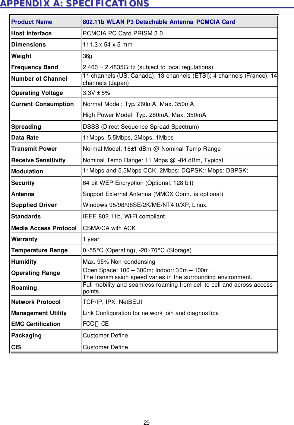
AirVast Technology Inc. 802.11b WLAN PCMCIA Card W/Detachable Antenna
UserManual.wiki
>
AirVast Technology
>
WN113SH18 User Manual
>
User Manual
Contents
1.
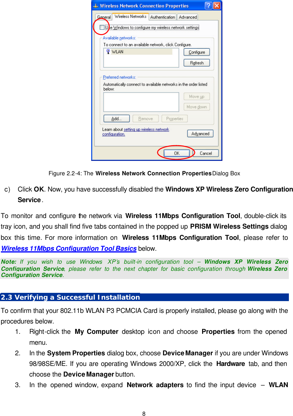
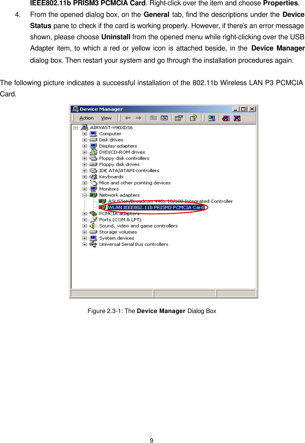
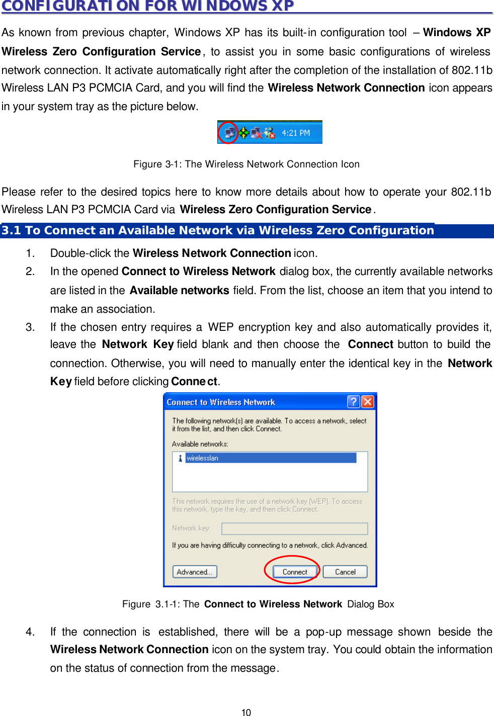
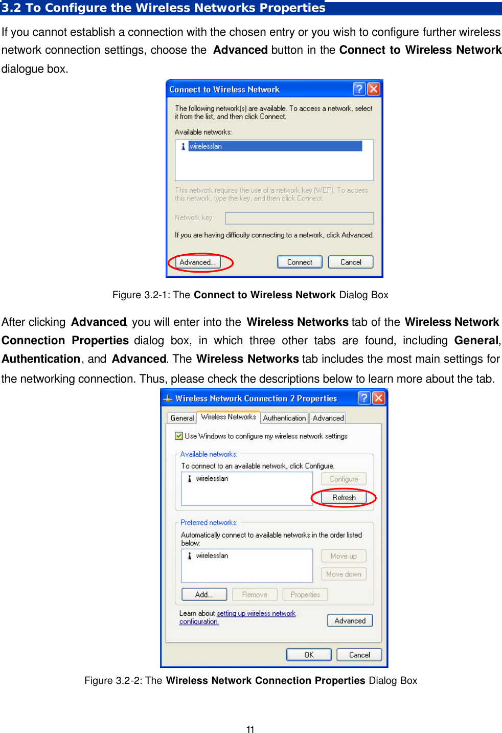
User Manual
2.
OEM installation guide
User Manual
Navigation menu
Upload a User Manual
Namespaces
Wiki Guide
HTML
PDF
Info
Views
User Manual
Discussion / Help
Navigation