AirVast Technology WN360G 802.11g WLAN Mini PCI Card User Manual
AirVast Technology Inc. 802.11g WLAN Mini PCI Card
UserManual.wiki
>
AirVast Technology
>
WN360G User Manual
User Manual
Navigation menu
Upload a User Manual
Namespaces
Wiki Guide
HTML
PDF
Info
Views
User Manual
Discussion / Help
Navigation
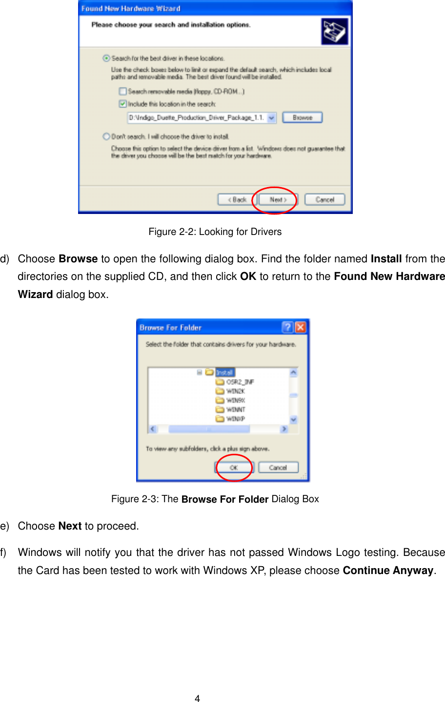
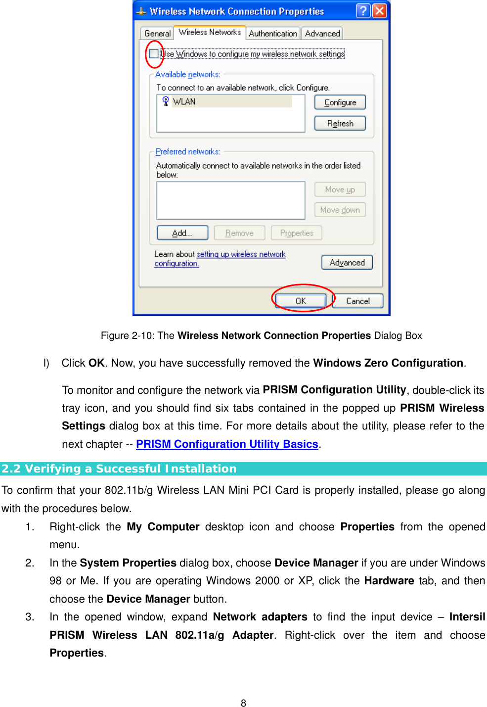
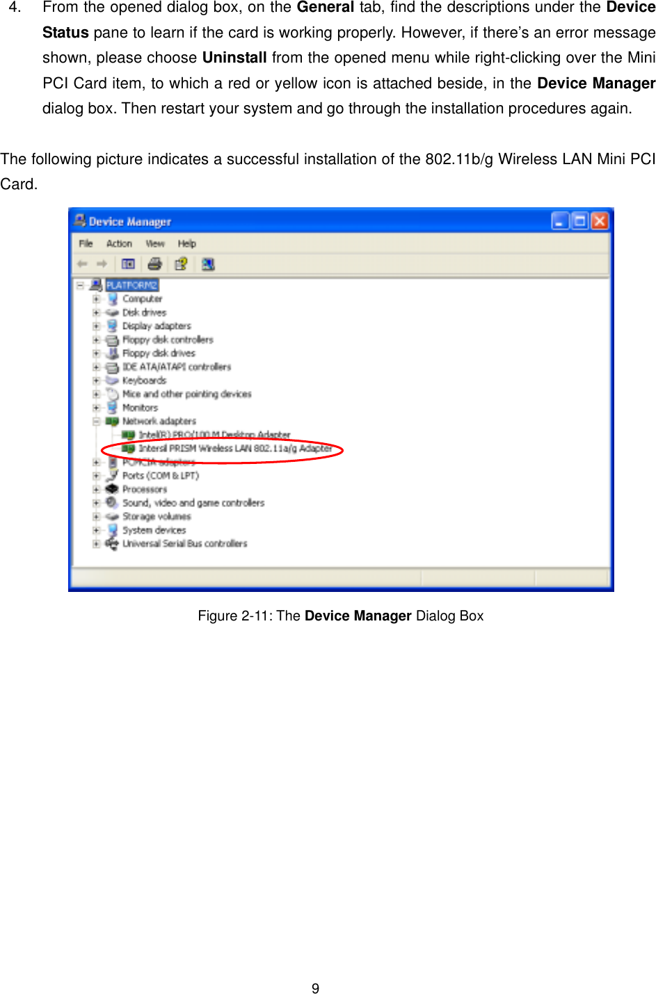
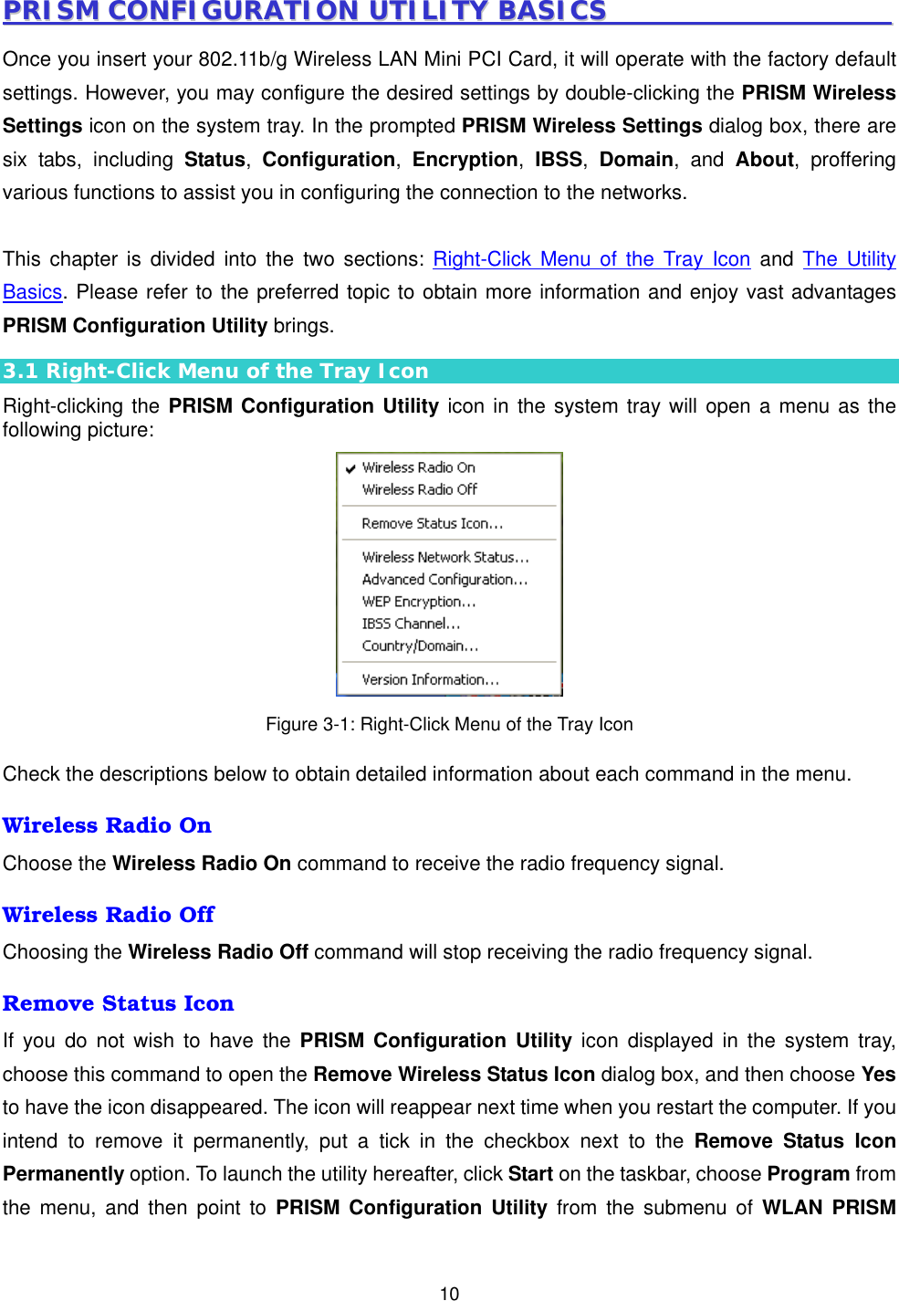
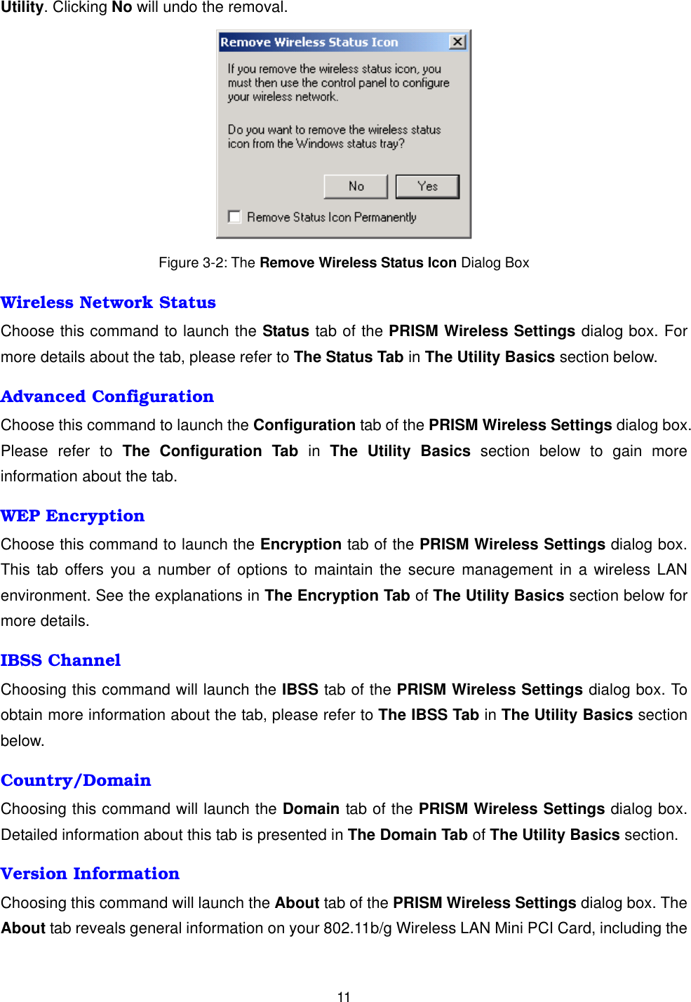
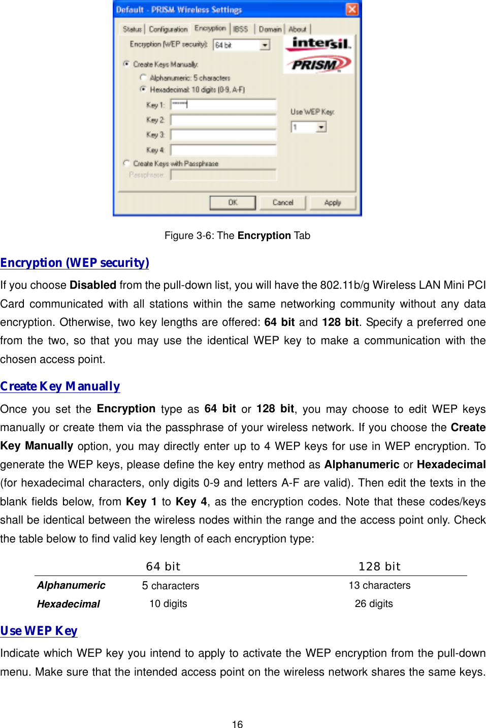
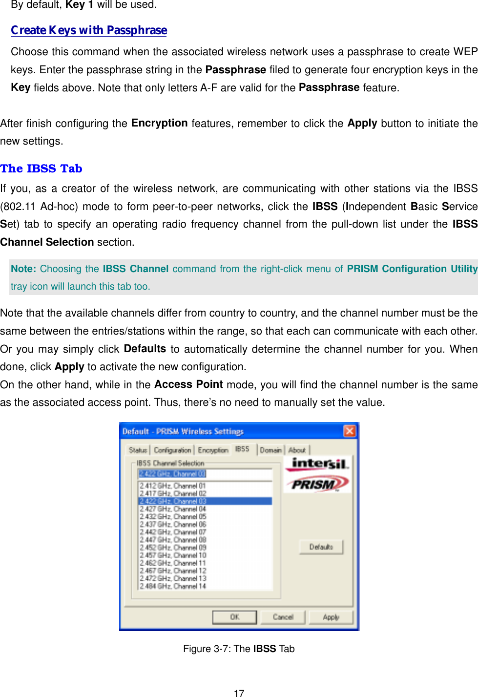
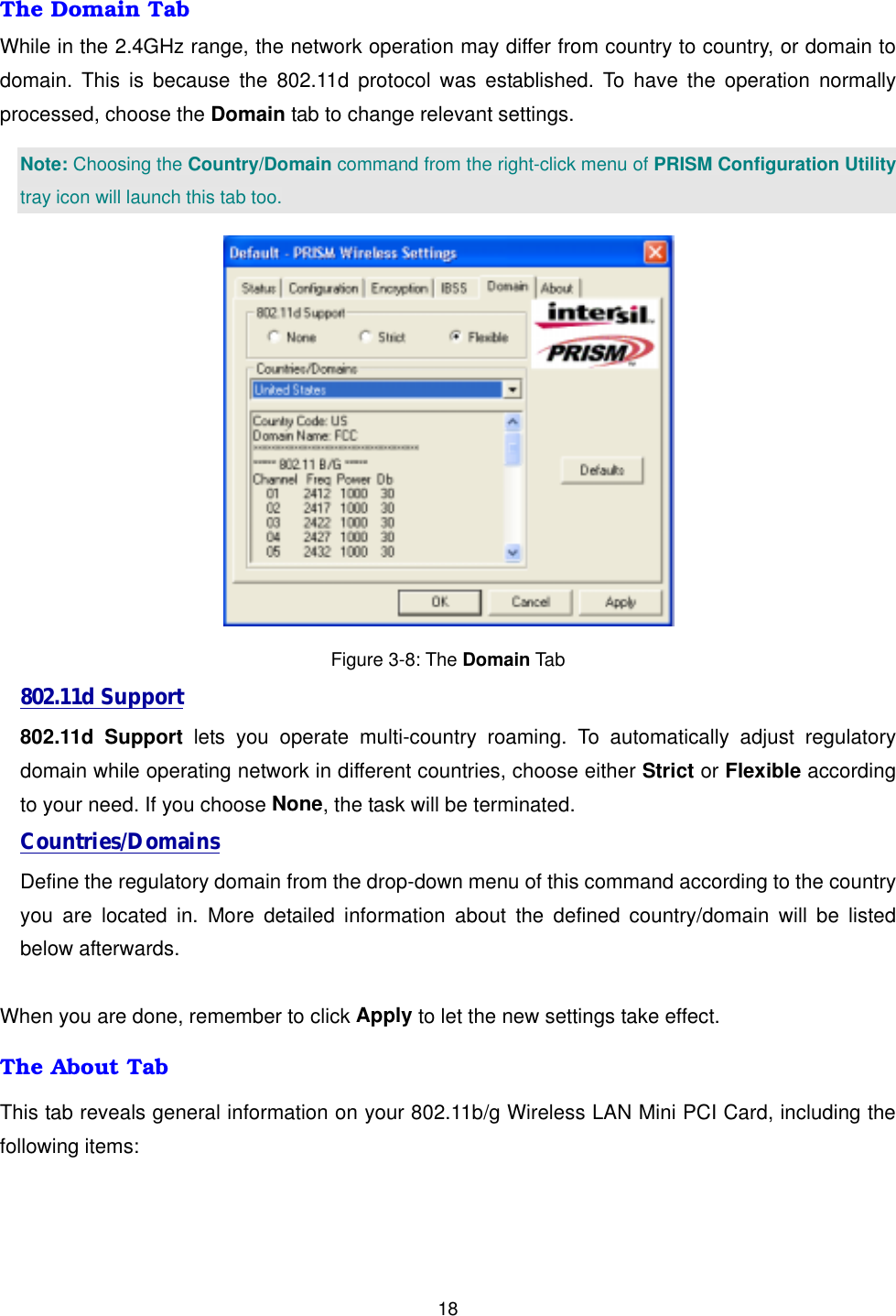
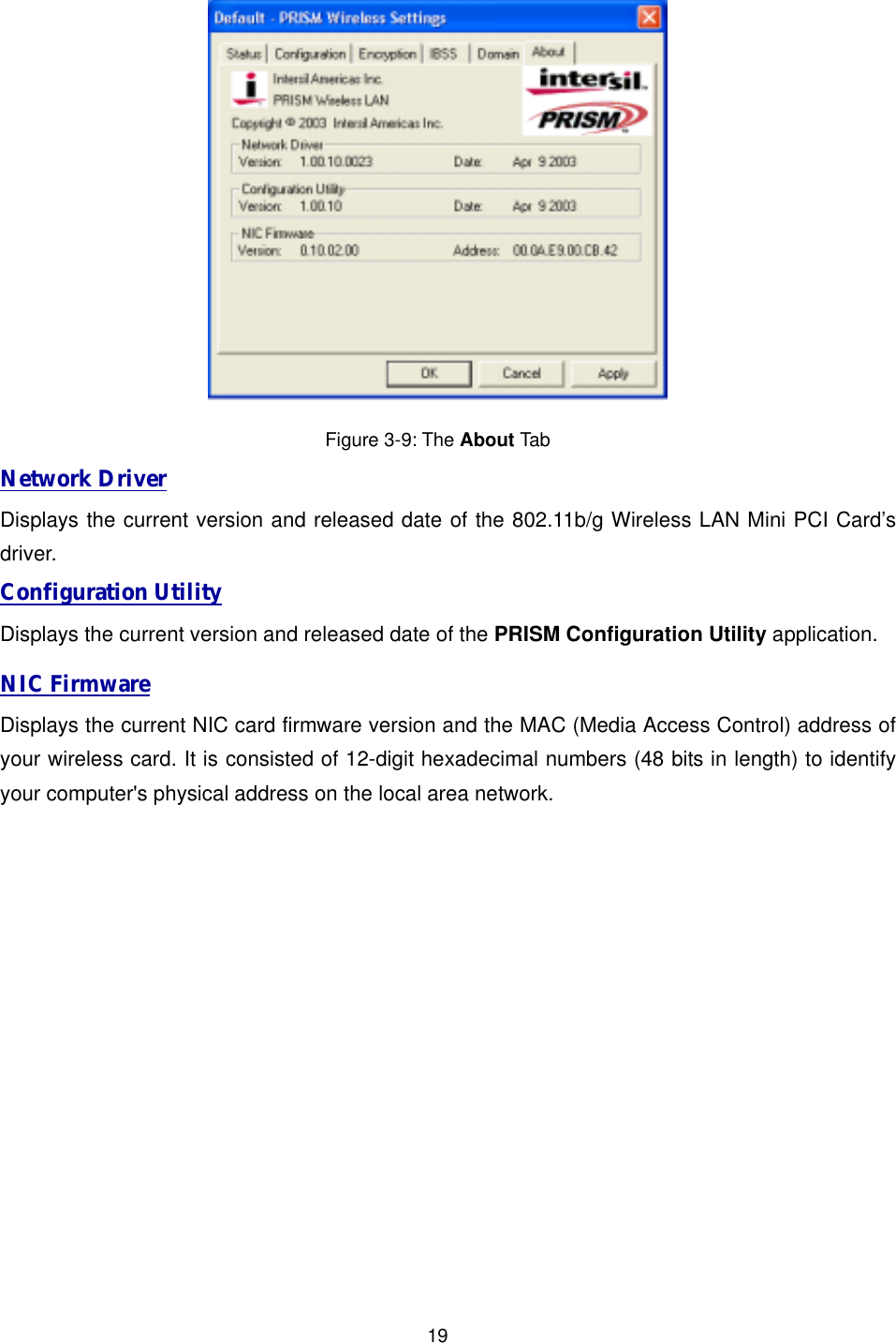
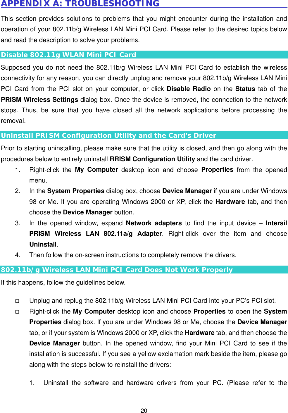
![3IINNSSTTAALLLLAATTIIOONN It’s free and easy for you to install your 802.11b/g Wireless LAN Mini PCI Card and the attached software - PRISM Configuration Utility. Simply with a few clicks of the mouse, you will succeed the completion of installation. To have the 802.11b/g Wireless LAN Mini PCI Card operated appropriately, please read and go along with the instructions below carefully. Here, we will illustrate the installation instructions based on Windows XP operating system. 2.1 Installation Procedures a) Insert the 802.11b/g Wireless LAN Mini PCI Card into your PC’s PCI slot. The Found New Hardware Wizard dialog box will appear because the system has detected the insertion of the Card. b) In the Found New Hardware Wizard dialog box, choose Install from a list or specific location [Advanced] and then click Next. Figure 2-1: The Found New Hardware Wizard Dialog Box c) When you see the following dialog box shown, choose Includes this location in the search under Search for the best driver in these locations.](https://usermanual.wiki/AirVast-Technology/WN360G/User-Guide-344041-Page-8.png)