AirWalk Communications AWEPPRO EdgePoint PRO User Manual Installation Guide
AirWalk Communications, Inc. EdgePoint PRO Installation Guide
Contents
- 1. Installation Guide
- 2. Reference Guide
Installation Guide

EdgePoint PRO Installation Guide
Version 1.0
February 2011
Prepared By
AirWalk Communications, Inc.
1830 North Greenville Ave
Richardson, TX, 75081
Phone: (972) 638-9400
Fax: (972) 638-9401
www.airwalkcom.com
FOR USE BY TRAINED TECHNICIANS ONLY

EdgePoint PRO Installation Guide
______________________________________________________________________________
AirWalk Proprietary and Confidential Page 2 of 19
Revision History
Version Date Person Description
0.1 01/04/2011 R MacLennan Initial Draft Document
0.2 02/04/2011 R Campman Added Plug and Play section
0.3 02/10/2011 A Sridhar Added Cluster info, LED deciphering section
1.0 Review changes

EdgePoint PRO Installation Guide
______________________________________________________________________________
AirWalk Proprietary and Confidential Page 3 of 19
Contents
1Introduction ..................................................................................................... 4
1.1Proprietary Information Notice ....................................................................... 4
1.2Purpose ...................................................................................................... 4
1.3Scope ......................................................................................................... 4
2Acronyms ......................................................................................................... 5
3eFemto Safety and Compliance Information .......................................................... 6
3.1Statement of Intent...................................................................................... 6
3.2Safety Precautions ....................................................................................... 6
3.3Regulatory Compliance Information ................................................................ 6
3.3.1Radio Interference (FCC 15.19 Statement) ................................................ 7
3.3.2Unauthorized Modifications (FCC 15.21 Statement) ..................................... 7
3.3.3Digital Device Interference (FCC 15.105 Statement) ................................... 7
4eFemto Device Installation .................................................................................. 8
4.1Overview .................................................................................................... 8
4.2eFemto Network Diagram .............................................................................. 9
4.2.1Network Requirements ......................................................................... 10
4.3Hardware Configuration .............................................................................. 11
5Installation Steps ............................................................................................ 13
5.1Contents within the Installation Kit ............................................................... 13
5.2eFemto Location for Installation ................................................................... 14
5.3Mount Bracket to Wall ................................................................................ 15
5.4Position Power Supply, Cables and Antennas .................................................. 15
5.5Secure eFemto to Bracket and Connect Cables ............................................... 16
5.6Powering Up the eFemto ............................................................................. 17
5.7eFemto Plug and Play Feature ...................................................................... 17
5.8Deciphering eFemto LEDs ............................................................................ 18

EdgePoint PRO Installation Guide
______________________________________________________________________________
AirWalk Proprietary and Confidential Page 4 of 19
1 Introduction
1.1 Proprietary Information Notice
THIS DOCUMENT IS THE PROPERTY OF AIRWALK COMMUNICATIONS, INC. THE
RECIPIENT MAY USE IT ONLY FOR THE PURPOSE FOR WHICH IT WAS
TRANSMITTED AND WILL BE RETURNED UPON REQUEST OR WHEN NO LONGER
NEEDED BY RECIPIENT. IT MAY NOT BE COPIED OR COMMUNICATED WITHOUT
THE WRITTEN CONSENT OF AIRWALK COMMUNICATIONS, INC.
1.2 Purpose
The AirWalk EdgePoint Pro Femto Cells, called eFemto throughout this document, are small,
easily installable miniature base stations designed to provide improved and enhanced
coverage inside buildings. Typically the eFemto cells are connected to the public Internet
and the operator’s network via Cable, DSL, on-premise fiber optic link, or a similar IP
backhaul technology. The eFemto cell offers benefits for both the subscribers as well the
operators. The subscribers get better voice service coverage and higher data throughput
while the operators are able to provide better coverage in spotty coverage areas and are
able to off-load traffic from the macro cellular network. In addition, indoor coverage
problems may be resolved by using the eFemto cell.
1.3 Scope
This document describes the installation procedure for the eFemto cell. The scope of this
document covers the description, environmental specifications, equipment location, cabling,
and installation followed by trouble shooting steps if required during the installation of the
eFemto device.

EdgePoint PRO Installation Guide
______________________________________________________________________________
AirWalk Proprietary and Confidential Page 5 of 19
2 Acronyms
1xEVDO 1x Evolution Data Optimized
1xRTT 1x Real Time Transmission
AAA Authentication, Authorization and Accounting
AN Access Network
BSC Base Station Controller
BTS Base Station Transceiver Subsystem
DHCP Dynamic Host Control Protocol
DNS Domain Name Server
DSCP Differentiated Services Code Point
FCC Federal Communications Commission
FSM Femto cell Station Manager
FQDN Fully Qualified Domain Name
GPS Global Positioning System
IKEv2 Internet Key Exchange version 2
IMS IP Multimedia Subsystem
IOS Interoperability Specification
ISAKMP Internet Security Association and Key Management Protocol
IPSec IP Security
LAN Local Area Network
LED Light Emitting Diode
MGW Media Gateway
O&M Operation and Maintenance
PCF Packet Control Function
RF Radio Frequency
RN Radio Network
RNC Radio Network Controller
RTP Real Time Protocol
SeGW Security Gateway
SIP Session Initiation Protocol
UDP User Datagram Protocol
VPN Virtual Private Network
WAN Wide Area Network
EdgePoint PRO Installation Guide
______________________________________________________________________________
AirWalk Proprietary and Confidential Page 6 of 19
3 eFemto Safety and Compliance Information
3.1 Statement of Intent
The AirWalk EdgePoint PRO Femto Cell is intended for use in a CDMA cellular infrastructure
radio access network. The responsible body shall be made aware that, if the equipment is
used in a manner not specified by the manufacturer, the protection provided by the
equipment may be impaired.
3.2 Safety Precautions
Power Sources
Use only power sources that are within the specified limits as designated on the equipment
labels. Use of power sources outside the specified limits is hazardous and may cause
personal injury or property damage.
Equipment Location
Equipment is meant for indoor use only and should be located inside the building. Use of
unprotected equipment outdoors is hazardous and may cause personal injury or property
damage.
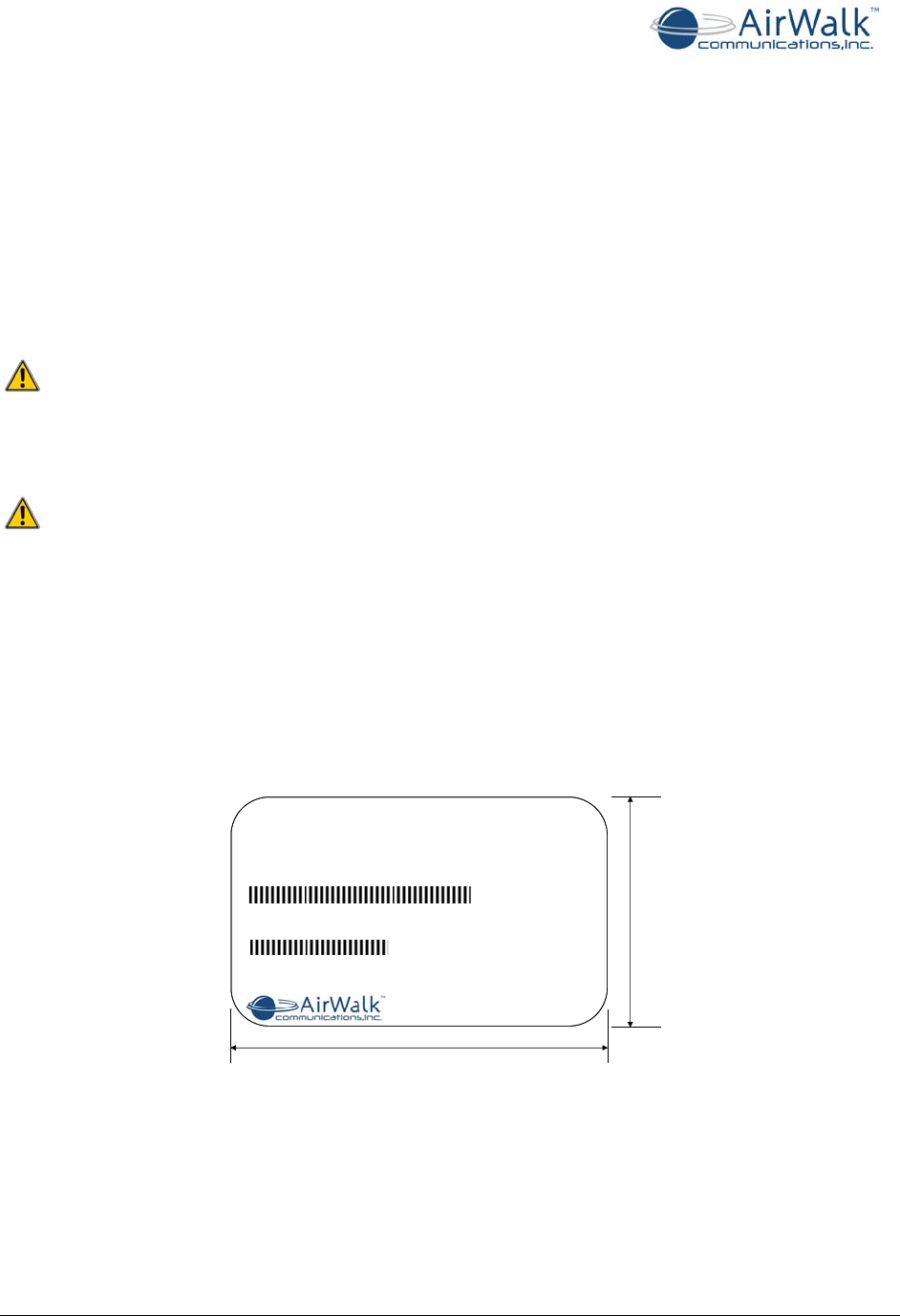
3.3 Regulatory Compliance Information
The FCC regulatory compliance information provided in this section is applicable only to
models equipped with an FCC Identification Number (FCC ID).
Enterprise Femtocell
MODEL: AWFExxxxxxx
FCC ID: R4HAWEPPRO
MAC ID:
76.0 mm
50.0 mm
DC IN: 12 VDC / 8A
AirWalk Communications., Inc Contact: +1-972-638-9400
0009D200000
Made In U.S.A.
SERIAL #:
AA00000A
Figure 1 - AirWalk eFemto FCC Label (SAMPLE)

EdgePoint PRO Installation Guide
______________________________________________________________________________
AirWalk Proprietary and Confidential Page 7 of 19
3.3.1 FCC Radiation Exposure Statement
This device complies with FCC’s RF radiation exposure limits set forth for an uncontrolled
environment under the following conditions:
• This device should be installed and operated such that a minimum separation
distance of 8 inches (20 cm) is maintained between the radiator (antenna) and the
user’s or nearby person’s body at all times.
3.3.2 Radio Interference (FCC 15.19 Statement)
This device complies with part 15 of the FCC Rules. Operation is subject to the following two
conditions: (1) This device may not cause harmful interference, and (2) This device must
accept any interference received, including interference that may cause undesired operation.
3.3.3 Unauthorized Modifications (FCC 15.21 Statement)
Persons or parties responsible for operation of this equipment are cautioned that any
changes or modifications not expressly approved by AirWalk Communications Incorporated
could void the user’s authority to operate this equipment.
3.3.4 Digital Device Interference (FCC 15.105 Statement)
This equipment has been tested and found to comply with the limits for a Class A digital
device, pursuant to part 15 of the FCC Rules. These limits are designed to provide
reasonable protection against harmful interference when the equipment is operated in a
commercial environment. This equipment generates, uses, and can radiate radio frequency
energy and, if not installed and used in accordance with the instruction manual, may cause
harmful interference to radio communications. Operation of this equipment in a residential
area is likely to cause harmful interference in which case the user will be required to correct
the interference at their expense.

EdgePoint PRO Installation Guide
______________________________________________________________________________
AirWalk Proprietary and Confidential Page 8 of 19
4 eFemto Device Installation
4.1 Overview
The eFemto is a compact cellular access point, supporting both cdma2000 1xRTT and
1xEVDO Rev0/Rev A subsystems. The combined functionalities of BTS, BSC, and PCF are
supported within the cdma2000 1xRTT sub system. Further, the eFemto contains the
capability for interworking standard IOS protocols to SIP messages on the back haul
network for cdma2000 1xRTT handsets. For the 1xEVDO sub system, the eFemto supports
the combined AN and PCF functionalities. The entire communication with the Operator’s
network goes through a secure IPSec tunnel. This tunnel originates from the eFemto and
terminates at the SeGW. The eFemto expands 3G cellular services inside buildings so mobile
users can experience full voice and data service in areas that have inconsistent or no
cellular signal. Typical installations include office buildings, warehouses, high rises,
convention centers and other in-building hot spots.
eFemto Advantages:
• Security: Secure and reliable connection into the operator’s network. The
eFemto uses a secure VPN tunnel to access an operator’s internal network. The
eFemto provides self as well as subscriber authentication to protect against fraud
and illegal usage of the device.
• Scalability: Scalable to any number of Femto cells within an operator’s network
with minimal impact to the existing infrastructure. Each eFemto is easily
configurable remotely from the operator’s network using FSM.
• Minimizing Interference: The eFemto comes equipped with internal hardware
and algorithms to minimize and mitigate RF interference towards existing
networks.
• Seamless Services Support: The eFemto services are compatible with any
standard-issue CDMA cellular phone or AirCard. The eFemto supports E911
emergency calls. Further it supports feature transparency with the CDMA Macro
network.
• Single Cell or Cluster Configuration Support with Mobility: The eFemto can
be deployed as a single RF cell or as a cluster of Femto cells. Peer-to-Peer soft
handoff is supported within the clusters. Support for user mobility with soft
handoff as well as hard handout from the Femto cell to the Macro.
• Long Term Performance: Once the device is installed, there is typically no
reason to move, or update the eFemto. This unit is also maintenance free and
requires no regular maintenance.
EdgePoint PRO Installation Guide
______________________________________________________________________________
AirWalk Proprietary and Confidential Page 9 of 19
4.1.1
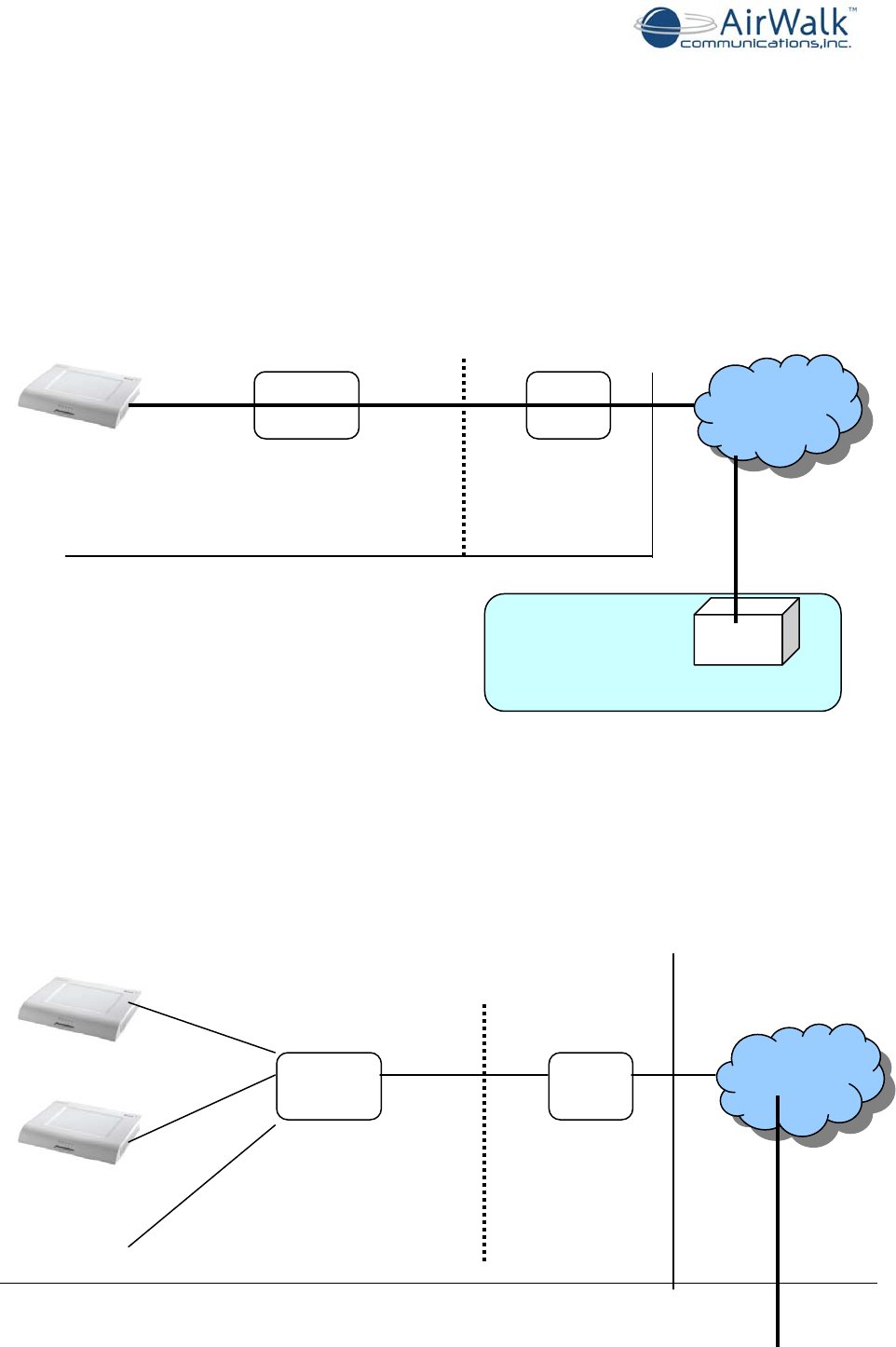
4.2 eFemto Network Diagram
The eFemto may be deployed as a single cell or multiple eFemtos may be deployed as a
cluster configuration. The device is IP-based and plugs in directly into an existing IP network
within the customer’s premises. The following diagram is a typical network diagram for a
standalone eFemto device within a customer’s premise.
Figure 2 - Single eFemto deployment network diagram
The following is a typical network diagram for multiple eFemto devices within a cluster
configuration in a customer’s site. In a cluster configuration, it should be ensured that all
the eFemtos within the cluster are reachable across the LAN. One way to do this is to
connect all the devices with the same IP subnet. If different IP subnets are used for a
cluster, then the routers must be updated accordingly for all subnets to be reachable.
LAN
Ethernet WAN
Router
Customer Premise
eFemto
Public
Internet
Operator’s Network SeGW
IPSec Tunnel
LAN
Ethernet WAN
Router
Public
Internet
EdgePoint PRO Installation Guide
______________________________________________________________________________
AirWalk Proprietary and Confidential Page 10 of 19
Figure 3 - Multiple eFemto deployed within a Cluster Configuration
4.2.1 Network Requirements
To get the eFemto device operating in optimal conditions, a customer’s IP network needs to
meet the following bandwidth and capacity requirements:
Service Usage
Type Bandwidth
Requirements Capacity Description
Maximum
Capacity 5 Mbps 29 voice calls and 32 active data users,
simultaneous
Idle 20 Kbps No active users
Voice Traffic Only
60 Kbps per call Maximum of 29 concurrent calls
Data Traffic Only
3 Mbps per device
(maximum) Maximum of 32 simultaneous data sessions
If multiple devices are installed throughout a campus there will be an increase of IP
traffic on the LAN
LAN Installation Considerations:
• The eFemto device supports standard RJ 45 LAN connection (100BASE-TX Ethernet
Switch/Router is recommended).
• The eFemto device supports DHCP as well as static IP addressing. The device is
shipped from the factory with the DHCP IP addressing scheme.
• The LAN needs to be able to access the customer’s WAN network to allow the eFemto
to connect to the operator’s network across the Internet.
• Signaling and traffic for Soft Handoff between cluster members goes across the LAN
network.
WAN Installation Considerations:
• Must Open UDP Ports 500 and 4500 for ISAKMP signaling between the eFemto and
the Security Gateway. Support for IPSec NAT-Traversal.
• Intrusion Prevention Systems should be properly configured for the device and
Security Gateway communication if required.
• Support for DSCP marked IP packets if possible on the customer’s IP network.
Operator’s Network SeGW
Customer Premise
IPSec Tunnel for
each device

EdgePoint PRO Installation Guide
______________________________________________________________________________
AirWalk Proprietary and Confidential Page 11 of 19
• For optimal performance of the device, a back haul bandwidth of 5 Mbits should be
reserved for each device.
• For cluster configuration, each device within the cluster needs its own linear back
haul bandwidth. All the devices within a cluster require the same back haul network
for optimal performance.
Static IP Addressing Scheme
The eFemto supports static IP addressing for the device. The device is shipped from the
factory using DHCP IP addressing scheme. The USB cable provided should be used to set
static IP address for the device (see EdgePoint PRO - USB Console User Guide for more
information).
When using static IP address for the device, along with the IP address, the Subnet Mask,
default Gateway and DNS server information should also be provided to the device using the
USB connection.
4.3 Hardware Configuration
The eFemto offers a unique combination of 1xRTT and EV-DO radio and controller in one
physical platform that is differentiated from other systems. The eFemto comes equipped
with a Network Listener module which aids the device in sniffing its RF environment to
reduce interference to existing Macro networks. The device also has an in-built GPS receiver
which is used to validate the position of the device once it becomes operational.
The following table lists the eFemto device specifications:
EdgePoint PRO Specifications
RADIO
Technology CDMA 1xRTT and 1xEV-DO Rev. A
Frequency Bands 1900 MHz
Simultaneous Calls Up to 29 simultaneous voice calls
Up to 32 active data sessions
Transmit Power 200 mW
Configuration 1 carrier / omni
CONTROLLER Handoff Soft / hard
Integrated BTS, BSC, RN, RNC, PCF and O&M
INTERFACES
Core Network Interface SIP/IMS
RTP/MGW
PDSN IP-10/100 Base T Ethernet – (A10,
A11)
AAA+HA IP-10/100 Base T Ethernet – (A12)
SeGW IKEv2
POWER SUPPLY AC 15 amps maximum / 120V AC
ENVIRONMENTAL Temperature Operating 0°C to 50°C (32°F to
122°F)
Humidity 0 to 95% non-condensing
HARDWARE Installation Wall mount
Dimensions (HxWxD) 12” x 14.6” x 2”

EdgePoint PRO Installation Guide
______________________________________________________________________________
AirWalk Proprietary and Confidential Page 12 of 19
Weight 6.5 lbs
(9 lbs with bracket)
Cooling Forced air
Type Indoor
EdgePoint PRO Installation Guide
______________________________________________________________________________
AirWalk Proprietary and Confidential Page 13 of 19
5 Installation Steps
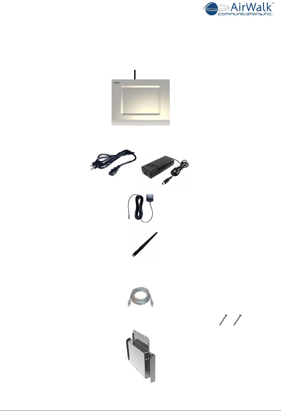
5.1 Contents within the Installation Kit
The contents of the installation kit are listed below:
1. EdgePoint PRO Femto Cell (1 unit)
2. Power Converter and Cable (1 unit each, 5 ft (1.5 m) cable)
3. GPS Antenna (1 unit)
4. RF Antenna (1 unit)
5. Ethernet Cable (1 unit, 16.4 ft (5 m) cable)
6. Mounting Bracket and Screws (1 unit, and 2 screws)
EdgePoint PRO Installation Guide
______________________________________________________________________________
AirWalk Proprietary and Confidential Page 14 of 19
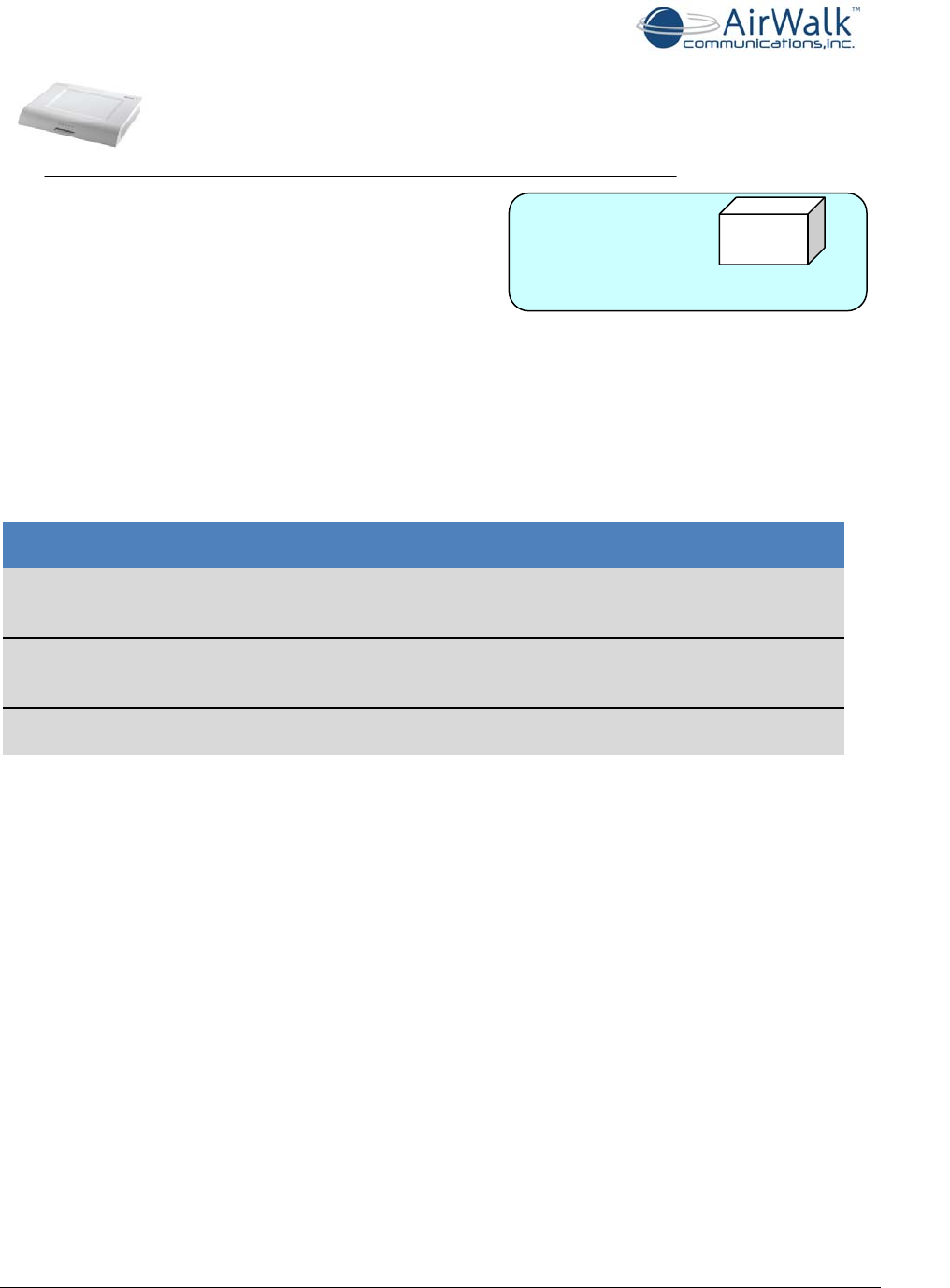
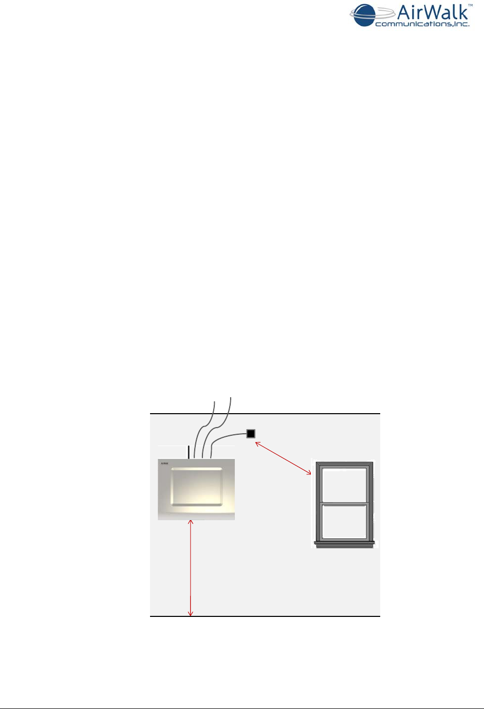
5.2 eFemto Location for Installation
The following list defines the eFemto location requirements for deployment inside the
building:
• Flat 24”x24” wall space so a physical clearance of 5” on all sides of the device is
observed to ensure efficient operation of the cooling fans and antennas
• A building support beam for mounting support (recommended)
• Access to a AC power source and breakers to accommodate up to 15 amps / 120
VAC (ceiling access is recommended)
• Access to an Ethernet port to connect the enterprise LAN line to the internet
backbone (ceiling access is recommended)
• Must be within 15 ft (5m) from a window that has no metal sheeting with a clear
view of the sky
• Moderate temperature between 32°F and 122°F
• Dry environment with relative humidity between 0 to 95% non-condensing
Equipment needed for installation:
• Drill or screwdriver with medium Phillips head
• Step ladder to install and connect the cables
• 3 screws size #10 pan head x 2” with washer to install mounting plate
• 3 wall anchors optional (if required for wall mounting)
>6ft(2m)
<15ft(5m)
GPSAntenna
Ethernet
connection
Power
connection
Figure 4 - Possible Mounting Location for an eFemto device
EdgePoint PRO Installation Guide
______________________________________________________________________________
AirWalk Proprietary and Confidential Page 15 of 19
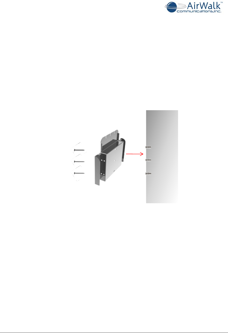
5.3 Mount Bracket to Wall
Once the location has been selected, mount the bracket to the wall.
1. Mount eFemto at least 6ft (2m) from floor
¾ Do not mount above ceiling or on ceiling
2. Use mounting bracket as a template to determine hole positioning and level the
bracket
3. Drill 3 wall anchors into the wall, if necessary. If mounting to a beam, no wall
anchors will be necessary.
4. Position the bracket lined up with the holes
5. Drive screws through the bracket to firmly secure it to the wall
Figure 5 - Mounting Bracket Installation
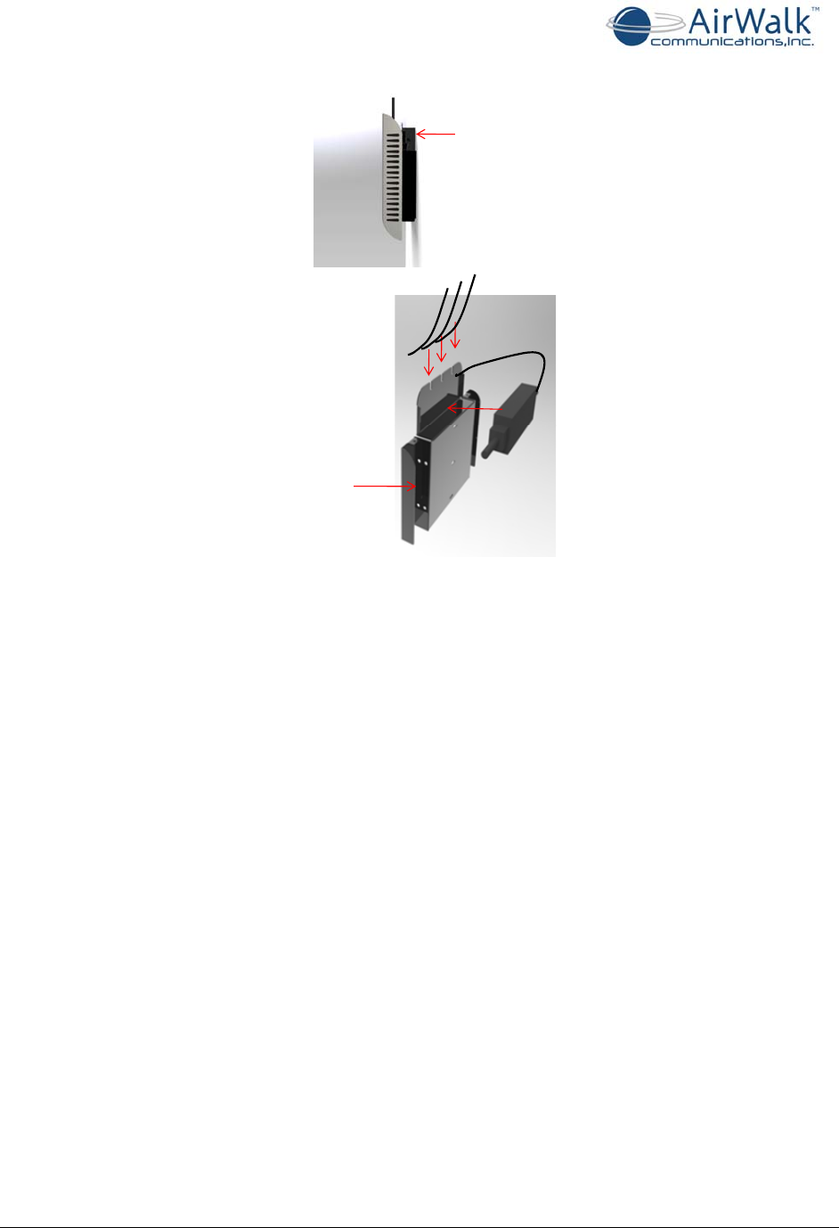
5.4 Position Power Supply, Cables and Antennas
Use the mounted bracket as a base support to:
1. Place power supply into designated location at top of bracket
2. Use side areas of bracket to roll excess cable slack and tie wrap access cable into
position
3. In the right cable guide space, pull power cable through to secure to device with
approximately 2” of clearance
4. In middle space, place Ethernet cable through the cable guide with approximately
2”of clearance
5. In the left space, place GPS antenna cable through the cable guide with
approximately 2”of clearance
6. Install the GPS antenna within 15 ft (5m) of a window with no metal sheeting and
with an open view of the sky
EdgePoint PRO Installation Guide
______________________________________________________________________________
AirWalk Proprietary and Confidential Page 16 of 19
Insertpower
supplyatthetop
ofthebracket
Drawcables
throughthe
cableguides
Rollexcess
cableslack
Figure 6 – Position Power Supply, Cables, and Antennas
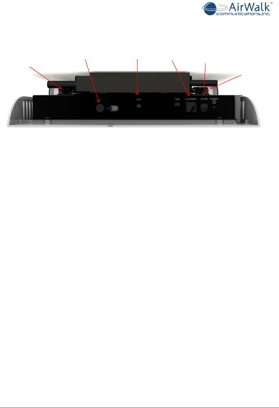
5.5 Secure eFemto to Bracket and Connect Cables
Follow the steps below to secure the eFemto cables:
1. Position the device onto the mounting bracket in line with 4 pegs. Lock the device
securely into the keyholes by sliding the device down.
2. Secure the cables from the cable guides on the mounting bracket and plug into the
device
¾ Connect RF antenna
¾ Connect GPS antenna
¾ Connect power
¾ Connect Ethernet
3. Secure 2 lock bracket screws to top on either side to mount device to bracket
**Note: The USB port will remain vacant
EdgePoint PRO Installation Guide
______________________________________________________________________________
AirWalk Proprietary and Confidential Page 17 of 19
Fastenlock
bracketscrews Fastenlock
bracketscrews
Connect
RFantenna
Connect
GPSantenna
Connect
Ethernet
cable
Connect
Power
cable
Figure 7 – Top view of eFemto displaying Cable Connection Points
5.6 Powering Up the eFemto
Once the eFemto has been wall mounted and all the cables have been connected, press the
power button on the top right side of the device. The device will take between 30 to 45
minutes to get ready for service when installed for the first time.
5.7 eFemto Plug and Play Feature
The eFemto works as a plug and play device when installed. The eFemto is shipped from the
factory with a factory image as well as factory configuration parameters stored within its
non-volatile memory location. The eFemto will automatically communicate with the
operator’s network to download a service image as well as perform various self
authentication and self configuration steps before turning its RF on to service the mobiles.
When the eFemto is powered on for the first time, it will follow the following steps:
• get an IP address assignment from LAN
• Initiate an IPSec tunnel establishment with the SeGW for communication with an
operator’s network
• Start the communication with the FSM to receive the service image from it
• Once a new service image has been downloaded from FSM, the eFemto will save this
image to its non-volatile memory area and will perform a self reboot
• After the reboot, the eFemto will setup the IPSec tunnel again with the SeGW, start
communication with the FSM and start acquiring a GPS lock
• It may take any time between 30 to 45 minutes for the eFemto to become
operational the first time that it is installed

EdgePoint PRO Installation Guide
______________________________________________________________________________
AirWalk Proprietary and Confidential Page 18 of 19
5.8 Deciphering eFemto LEDs
The eFemto device has five LEDs that indicate various operational status of the device.
These five LEDs are as follows from left to right on the device:
PWR: Indicates Power status of the device
LNK: Indicates the Ethernet access for the device
NET: Indicates the IP addressing as well as IPSec tunnel status
GPS: Indicates the GPS status of the device
SYS: System status
After power up, if all the five LEDs turn “Blue”, this is an indication that the device has been
configured by the FSM, all systems are ready and the RF on the device has been turned on
for services.
The following section describes what steps may be taken if any of these LEDs turn “Red”
during the power up of the device:
PWR: This LED is always “Blue” indicating that the device is receiving power. If this LED is
not illuminated, check the following:
• Ensure that the power cable is plugged into a working wall socket
• Ensure that the power cable is plugged into the eFemto
• Check the power switch on top right corner of the eFemto
• If other LEDs are blinking, then it is possible that this LED is broken
LNK: This LED defines the device status regarding Ethernet connectivity to the customer’s
LAN network. If the Ethernet cable has been connected to the device and the device is able
to access the LAN, then this LED will turn “Blue” and blink to indicate network activity.
This LED will turn “Red” if Ethernet cable is removed or not connected properly on the
device.
If this LED is blinking or solid “Red”, check the following:
• Ensure that the Ethernet cable is good
• Ensure that the LAN Ethernet Switch/Router is working
• Get help from customer’s IT to resolve any LAN issues
NET: This LED defines the IP address and IPSec tunnel status of the device. On power up,
this LED will be blinking “Red” until an IP address is obtained from the DHCP Server. The
LED will be blinking “Blue” while IPSec tunnel is being established and will turn “Red” during
the wait time due to a failure in establishing IPSec tunnel with the SeGW.
If this LED is blinking “Red”, check the following:
• The DHCP server is accessible to the device on the LAN
• Get help from the customer’s IT to resolve any DHCP server issues providing an IP
address to the device on the LAN

EdgePoint PRO Installation Guide
______________________________________________________________________________
AirWalk Proprietary and Confidential Page 19 of 19
If this LED turns “Red”, check the following:
• The device is able to send and receive signaling messages with the SeGW using the
WAN
• The SeGW has been configured with the valid information for this device
• Ensure that the DNS server information provided by the DHCP server is valid and the
DNS server is able to resolve the SeGW FQDN
GPS: This LED defines the GPS lock status of the device. This LED will turn “Red” if there
are not enough tracking satellites visible to the device. It will blink “Blue” when trying to fix
a GPS lock and will turn “Blue” when GPS lock has been achieved on the device.
If this LED turns “Red”, check the following:
• Ensure that the GPS cabling is connected on the device
• Reposition the GPS antenna
SYS: This LED defines different states of the device. This LED will blink “Blue” when the
device is trying to register with the IMS Core. This LED will blink “Red” if the back haul
bandwidth is not enough for calls.
ACTIVITY POW LNK SYS NET GPS
Power on
Blue Off Blue
Flashing Off Off
IP information
Complete Blue Blue Blue
Flashing Off Off
[LINK] Blue if physically connected. Additionally, it will blink per network activity.
IP Sec Tunnel
Connected Blue Blue Blue
Flashing Blue Off
[NET] Red flashing until the eFemto gets the DHCP IP address. Blue flashing while IPSec tunnel is
being established, Red if waiting due to earlier failure in making the tunnel establishment
GPS Lock
Established Blue Blue Blue
Flashing Blue Blue
[GPS] Red if there are not enough tracking satellites, Blue blinking with satellites but not yet locked,
and Blue if locked
System
Reboot Blue Off Off Off Off
IMS/SIP
Registration &
Calibration Blue Blue Blue
Flashing Blue Blue
[SYS] Blue flashing until SIP is registered for 1x and/or PDSN keep alive for DO, Red blinking if the
bandwidth is not enough for a call
Frequency Lock &
System Ready Blue Blue Blue Blue Blue