Airespace AMAP1200AB 802.11 Dual Band Access Point User Manual Airespace Product Guide
Airespace 802.11 Dual Band Access Point Airespace Product Guide
Users Manual
10/10/03 © 2003 Airespace, Inc. All Rights Reserved.
90-100584-004
Welcome to the Airespace Product Guide!Airespace Product Guide
Airespace System 1.2: Last Updated October 10, 2003
Refer to the OVERVIEWS section to see a big picture view of Airespace products and
features.
See the SOLUTIONS section to look through real-world network and application-
specific solutions to real-world problems.
Go to the TASKS section to find detailed instructions on how to install, configure, use,
and troubleshoot Airespace products and supported 802.11 networks.
Visit the REFERENCES section to see technical information, such as the Access Point
Site Survey Guide, Quick Installation Guides, Web Browser Online Help files, and
Release Notes.
FCC Statements for Airespace Switches and Appliances
FCC Statements for Airespace APs
Legal Information
Airespace Technical Support
Airespace System Release Notes


10/10/03 Legal Information
90-100584-004 Airespace Product Guide iii
Limited Product WarrantyLimited Pr oduct Warranty
The following describes the Airespace, Inc. standard Product Warranty for End Customers.
ProductsProducts
•Airespace Wireless Switch (40XX) Family
•Airespace WLAN Appliance (41XX) Family
•Airespace Access Point (1200) Family
Limited WarrantyLimited Warranty
Airespace warrants that:
•For a period of one (1) year from the date of installation of the Product at the End Customer’s
site but not to exceed twenty-four (24) months after date of shipment by Airespace, the
Hardware shall free from defects in materials and workmanship.
•For a period of three (3) months from the date of installation of the Product but not to exceed
fifteen (15) months after date of shipment by Airespace, the Software shall substantially
conform to the applicable specifications in Airespace’s then-current published documentation.
The date of shipment by Airespace is set forth on the packaging material in which the Product is
shipped. This limited warranty extends only to you the original purchaser of the Product.
Exclusive RemedyExclusive Remedy
Your sole remedy under the limited warranty described above is, at Airespace’s sole option and
expense, the repair or replacement of the non-conforming Product or refund of the purchase price of
the non-conforming Products. Airespace’s obligation under this limited warranty is subject to compli-
ance with Airespace’s then-current Return Material Authorization (“RMA”) procedures. All replaced
Products will become the property of Airespace. Exchange Products not returned to Airespace will be
invoiced at full Product list prices. Replacement Products may be new, reconditioned or contain refur-
bished materials. In connection with any warranty services hereunder, Airespace may in its sole
discretion modify the Product at no cost to you to improve its reliability or performance.
Warranty Claim ProceduresWarranty Claim Procedures
Should a Product fail to conform to the limited warranty during the applicable warranty period as
described above, Airespace must be notified during the applicable warranty period in order to have any
obligation under the limited warranty.
The End Customer or their designated reseller must obtain a Return Material Authorization number
(RMA number) from Airespace for the non-conforming Product and the non-conforming Product must
be returned to Airespace according to the then-current RMA procedures. The End Customer or their
designated reseller is responsible to ensure that the shipments are insured, with the transportation
charges prepaid and that the RMA number is clearly marked on the outside of the package. Airespace
will not accept collect shipments or those returned without an RMA number clearly visible on the
outside of the package.
Exclusions and RestrictionsExclusions and Restriction s
Airespace shall not be responsible for any software, firmware, information or memory data contained
in, stored on or integrated with any Product returned to Airespace pursuant to any warranty or repair.
Upon return of repaired or replaced Products by Airespace, the warranty with respect to such Products
will continue for the remaining unexpired warranty or sixty (60) days, whichever is longer. Airespace
may provide out-of-warranty repair for the Products at its then-prevailing repair rates.

10/10/03 Legal Information
90-100584-004 Airespace Product Guide iv
The limited warranty for the Product does not apply if, in the judgment of Airespace, the Product fails
due to damage from shipment, handling, storage, accident, abuse or misuse, or it has been used or
maintained in a manner not conforming to Product manual instructions, has been modified in any way,
or has had any Serial Number removed or defaced. Repair by anyone other than Airespace or an
approved agent will void this warranty.
EXCEPT FOR ANY EXPRESS LIMITED WARRANTIES FROM AIRESPACE SET FORTH ABOVE, THE
PRODUCT IS PROVIDED “AS IS”, AND AIRESPACE AND ITS SUPPLIERS MAKE NO WARRANTY,
EXPRESS, IMPLIED, STATUTORY OR OTHERWISE, WITH RESPECT TO PRODUCT OR ANY PART
THEREOF, INCLUDING WITHOUT LIMITATION ANY IMPLIED WARRANTY OF TITLE, MERCHANTABILITY,
FITNESS FOR A PARTICULAR PURPOSE, NON-INFRINGEMENT, OR THOSE ARISING FROM COURSE OF
PERFORMANCE, DEALING, USAGE OR TRADE. AIRESPACE’S SUPPLIERS MAKE NO DIRECT WARRANTY
OF ANY KIND TO END CUSTOMER FOR THE LICENSED MATERIALS. NEITHER AIRESPACE NOR ANY OF
ITS SUPPLIERS WARRANT THAT THE LICENSED MATERIALS OR ANY PART THEREOF WILL MEET END
CUSTOMER'S REQUIREMENTS OR BE UNINTERRUPTED, OR ERROR-FREE, OR THAT ANY ERRORS IN
THE PRODUCT WILL BE CORRECTED. SOME STATES/JURISDICTIONS DO NOT ALLOW THE EXCLUSION
OF IMPLIED WARRANTIES SO THE ABOVE EXCLUSIONS MAY NOT APPLY TO END CUSTOMER. THIS
LIMITED WARRANTY GIVES END CUSTOMER SPECIFIC LEGAL RIGHTS. END CUSTOMER MAY ALSO
HAVE OTHER RIGHTS, WHICH VARY FROM STATE/JURISDICTION TO STATE/JURISDICTION.
TO THE MAXIMUM EXTENT PERMITTED BY APPLICABLE LAW, IN NO EVENT SHALL AIRESPACE OR ITS
SUPPLIERS BE LIABLE FOR THE COST OF PROCUREMENT OF SUBSTITUTE GOODS OR SERVICES, LOSS
OF PROFITS, OR FOR ANY SPECIAL, CONSEQUENTIAL, INCIDENTAL, PUNITIVE OR INDIRECT DAMAGES
(OR DIRECT DAMAGES IN THE CASE OF AIRESPACE’S SUPPLIERS) ON ANY THEORY OF LIABILITY,
WHETHER IN CONTRACT, TORT (INCLUDING WITHOUT LIMITATION NEGLIGENCE), STRICT LIABILITY
OR OTHERWISE ARISING OUT OF OR RELATED TO THE PRODUCT OR ANY USE OR INABILITY TO USE
THE PRODUCT. AIRESPACE’S TOTAL LIABILITY ARISING OUT OF OR RELATED TO THE PRODUCT, OR
USE OR INABILITY TO USE THE PRODUCT, WHETHER IN CONTRACT, TORT (INCLUDING WITHOUT
LIMITATION NEGLIGENCE), STRICT LIABILITY OR OTHERWISE, SHALL NOT EXCEED THE PRICE PAID
FOR THE PRODUCT. THE LIMITATIONS SET FORTH IN THIS SECTION SHALL APPLY EVEN IF AIRESPACE
AND/OR ITS SUPPLIERS ARE ADVISED OF THE POSSIBILITY OF SUCH DAMAGE, AND NOTWITH-
STANDING THE FAILURE OF ESSENTIAL PURPOSE OF ANY LIMITED REMEDY. AIRESPACE NEITHER
ASSUMES NOR AUTHORIZES ANY OTHER PERSON TO ASSUME FOR IT ANY OTHER LIABILITY IN
CONNECTION WITH THE SALE, INSTALLATION, MAINTENANCE OR USE OF ITS PRODUCTS.

10/10/03 Legal Information
90-100584-004 Airespace Product Guide v
Software License AgreementSoftware License Agreement
PLEASE READ THIS SOFTWARE LICENSE AGREEMENT (“AGREEMENT”) CAREFULLY BEFORE USING THE SOFTWARE AND ASSOCIATED
DOCUMENTATION THAT IS PROVIDED WITH THIS AGREEMENT (“SOFTWARE,” “DOCUMENTATION,” AND COLLECTIVELY, “LICENSED
MATERIALS”).
BY USING ANY LICENSED MATERIALS, YOU ACKNOWLEDGE THAT YOU HAVE READ AND UNDERSTOOD ALL THE TERMS AND CONDI-
TIONS OF THIS AGREEMENT AND YOU WILL BE CONSENTING TO BE BOUND BY THEM. IF YOU DO NOT ACCEPT THESE TERMS AND
CONDITIONS, DO NOT USE THE LICENSED MATERIALS AND RETURN THE LICENSED MATERIALS AND ANY EQUIPMENT PROVIDED BY
AIRESPACE IN CONNECTION THEREWITH (“EQUIPMENT”) UNUSED IN THE ORIGINAL SHIPPING CONTAINER TO THE PLACE OF PUR-
CHASE FOR A FULL REFUND.
Software may be provided by Airespace on a standalone basis (“Standalone Software”) or it may be provided embedded in Equipment
(“Embedded Software”).
1. License.
(a) Subject to the terms and conditions of this Agreement, Airespace, Inc. (“Airespace”), grants to you (“Licensee”) a limited,
non-exclusive, non-transferable license, without the right to sublicense: (i) to install and use the Standalone Software, in object code
format only, on computer hardware for which all corresponding license fees have been paid; (ii) use one (1) copy of the Embedded
Software, in object code format only, solely as embedded in Equipment, each solely in accordance with the Documentation for Licens-
ee’s internal business purposes.
(b) The license set forth above does not include any rights to and Licensee shall not (i) reproduce (except as set forth in Section
1(c)), modify, translate or create any derivative work of all or any portion of the Licensed Materials or Equipment, (ii) sell, rent, lease,
loan, provide, distribute or otherwise transfer all or any portion of the Licensed Materials (except as set forth in Section 1(f)), (iii)
reverse engineer, reverse assemble or otherwise attempt to gain access to the source code of all or any portion of the Licensed Ma-
terials or Equipment, (iv) use the Licensed Materials for third-party training, commercial time-sharing or service bureau use, (v) re-
move, alter, cover or obfuscate any copyright notices, trademark notices or other proprietary rights notices placed or embedded on
or in the Licensed Materials or Equipment, (vi) use any component of the Software or Equipment other than solely in conjunction with
operation of the Software and as applicable, Equipment, (vii) unbundle any component of the Software or Equipment, (viii) use any
component of the Software for the development of or in conjunction with any software application intended for resale that employs
any such component, (ix) use the Licensed Materials or Equipment in life support systems, human implantation, nuclear facilities or
systems or any other application where failure could lead to a loss of life or catastrophic property damage, or (x) cause or permit any
third party to do any of the foregoing.
If Licensee is a European Union resident, Licensee acknowledges that information necessary to achieve interoperability of the Software
with other programs is available upon request.
(c) Licensee may make a single copy of the Standalone Software and Documentation solely for its back-up purposes; provided
that any such copy is the exclusive property of Airespace and its suppliers and includes all copyright and other intellectual property
right notices that appear on the original.
(d) Airespace may provide updates, corrections, enhancements, modifications or bug fixes for the Licensed Materials (“Up-
dates”) to Licensee. Any such Update shall be deemed part of the Licensed Materials and subject to the license and all other terms
and conditions hereunder.
(e) Airespace shall have the right to inspect and audit Licensee’s use, deployment, and exploitation of the Licensed Materials
for compliance with the terms and conditions of this Agreement.
(f) Licensee shall have the right to transfer the Embedded Software as embedded in Equipment in connection with a transfer
of all of Licensee’s right, title and interest in such Equipment to a third party; provided, that, Licensee transfers the Embedded Software
and any copies thereof subject to the terms and conditions of this Agreement and such third party agrees in writing to be bound by
all the terms and conditions of this Agreement.
(g) Notwithstanding anything to the contrary herein, certain portions of the Software are licensed under and Licensee's use of
such portions are only subject to the GNU General Public License version 2. If Licensee or any third party sends a request in writing
to Airespace at 110 Nortech Parkway, San Jose CA 95134, ATTN: Contracts Administration, Airespace will provide a complete ma-
chine-readable copy of the source code of such portions for a nominal cost to cover Airespace's cost in physically providing such code.
2. Ownership. Airespace or its suppliers own and shall retain all right, title and interest (including without limitation all intellectual
property rights), in and to the Licensed Materials and any Update, whether or not made by Airespace. Licensee acknowledges that the
licenses granted under this Agreement do not provide Licensee with title to or ownership of the Licensed Materials, but only a right of
limited use under the terms and conditions of this Agreement. Except as expressly set forth in Section 1, Airespace reserves all rights
and grants Licensee no licenses of any kind hereunder. All information or feedback provided by Licensee to Airespace with respect to
the Software or Equipment shall be Airespace’s property and deemed confidential information of Airespace.
3. Confidentiality. Licensee agrees that the Licensed Materials contain confidential information, including trade secrets, know-how,
and information pertaining to the technical structure or performance of the Software, that is the exclusive property of Airespace as
between Licensee and Airespace. In addition, Airespace’s confidential information includes any confidential or trade secret information
related to the Licensed Materials. During the period this Agreement is in effect and at all times thereafter, Licensee shall maintain
Airespace’s confidential information in confidence and use the same degree of care, but in no event less than reasonable care, to avoid
disclosure of Airespace’s confidential information as it uses with respect to its own confidential and proprietary information of similar
type and importance. Licensee agrees to only disclose Airespace’s confidential information to its directors, officers and employees who
have a bona fide need to know solely to exercise Licensee’s rights under this Agreement and to only use Airespace’s confidential in-
formation incidentally in the customary operation of the Software and Equipment. Licensee shall not sell, license, sublicense, publish,
display, distribute, disclose or otherwise make available Airespace’s confidential information to any third party nor use such informa-
tion except as authorized by this Agreement. Licensee agrees to immediately notify Airespace of the unauthorized disclosure or use
of the Licensed Materials and to assist Airespace in remedying such unauthorized use or disclosure. It is further understood and agreed
that any breach of this Section 3 or Section 1(b) is a material breach of this Agreement and any such breach would cause irreparable
harm to Airespace and its suppliers, entitling Airespace or its suppliers to injunctive relief in addition to all other remedies available at
law.
4. Limited Warranty & Disclaimer. Any limited warranty for the Licensed Materials and Airespace’s sole and exclusivity liability
thereunder is as set forth in Airespace’s standard warranty documentation. In addition, any limited warranty for the Software does
not apply to any component of the Software but only to the Software as a whole. EXCEPT FOR ANY EXPRESS LIMITED WARRANTIES
FROM AIRESPACE IN SUCH DOCUMENTATION, THE LICENSED MATERIALS ARE PROVIDED “AS IS”, AND AIRESPACE AND ITS SUPPLI-
ERS MAKE NO WARRANTY, EXPRESS, IMPLIED, STATUTORY OR OTHERWISE, WITH RESPECT TO LICENSED MATERIALS OR ANY PART

10/10/03 Legal Information
90-100584-004 Airespace Product Guide vi
THEREOF, INCLUDING WITHOUT LIMITATION ANY IMPLIED WARRANTY OF TITLE, MERCHANTABILITY, FITNESS FOR A PARTICULAR
PURPOSE, NONINFRINGEMENT, OR THOSE ARISING FROM COURSE OF PERFORMANCE, DEALING, USAGE OR TRADE. AIRESPACE’S
SUPPLIERS MAKE NO DIRECT WARRANTY OF ANY KIND TO LICENSEE FOR THE LICENSED MATERIALS. NEITHER AIRESPACE NOR ANY
OF ITS SUPPLIERS WARRANT THAT THE LICENSED MATERIALS OR ANY PART THEREOF WILL MEET LICENSEE’S REQUIREMENTS OR
BE UNINTERRUPTED, OR ERROR-FREE, OR THAT ANY ERRORS IN THE LICENSED MATERIALS WILL BE CORRECTED. SOME STATES/
JURISDICTIONS DO NOT ALLOW THE EXCLUSION OF IMPLIED WARRANTIES SO THE ABOVE EXCLUSIONS MAY NOT APPLY TO LIC-
ENSEE. THIS LIMITED WARRANTY GIVES LICENSEE SPECIFIC LEGAL RIGHTS. LICENSEE MAY ALSO HAVE OTHER RIGHTS, WHICH
VARY FROM STATE/JURISDICTION TO STATE/JURISDICTION.
5. Term and Termination. This Agreement is effective until terminated. License may terminate this Agreement at any time by de-
stroying all copies of the Software. This Agreement and all licenses granted hereunder will terminate immediately without notice from
Airespace if Licensee fails to comply with any provision of this Agreement. Upon any termination, Licensee must destroy all copies of
the Licensed Materials. Sections 1(b), 2, 3, 4(b), 5, 6, 7, 8, 9 and 10 shall survive any termination of this Agreement.
6. Export. The Software is specifically subject to U.S. Export Administration Regulations. Licensee agrees to strictly comply with
all export, re-export and import restrictions and regulations of the Department of Commerce or other agency or authority of the United
States or other applicable countries, and not to transfer, or authorize the transfer of, directly or indirectly, the Software or any direct
product thereof to a prohibited country or otherwise in violation of any such restrictions or regulations. Licensee’s failure to comply
with this Section is a material breach of this Agreement. Licensee acknowledges that Licensee is not a national of Cuba, Iran, Iraq,
Libya, North Korea, Sudan or Syria or a party listed in the U.S. Table of Denial Orders or U.S. Treasury Department List of Specially
Designated Nationals.
7. Government Restricted Rights. As defined in FAR section 2.101, DFAR section 252.227-7014(a)(1) and DFAR section
252.227-7014(a)(5) or otherwise, the Software provided in connection with this Agreement are “commercial items,” “commercial com-
puter software” and/or “commercial computer software documentation.” Consistent with DFAR section 227.7202, FAR section 12.212
and other sections, any use, modification, reproduction, release, performance, display, disclosure or distribution thereof by or for the
U.S. Government shall be governed solely by the terms of this Agreement and shall be prohibited except to the extent expressly per-
mitted by the terms of this Agreement. Any technical data provided that is not covered by the above provisions shall be deemed “tech-
nical data-commercial items” pursuant to DFAR section 227.7015(a). Any use, modification, reproduction, release, performance,
display or disclosure of such technical data shall be governed by the terms of DFAR section 227.7015(b).
8. Limitation of Liability. TO THE MAXIMUM EXTENT PERMITTED BY APPLICABLE LAW, IN NO EVENT SHALL AIRESPACE OR ITS
SUPPLIERS BE LIABLE FOR THE COST OF PROCUREMENT OF SUBSTITUTE GOODS OR SERVICES, LOSS OF PROFITS, OR FOR ANY
SPECIAL, CONSEQUENTIAL, INCIDENTAL, PUNITIVE OR INDIRECT DAMAGES (OR DIRECT DAMAGES IN THE CASE OF AIRESPACE’S
SUPPLIERS) ON ANY THEORY OF LIABILITY, WHETHER IN CONTRACT, TORT (INCLUDING WITHOUT LIMITATION NEGLIGENCE),
STRICT LIABILITY OR OTHERWISE ARISING OUT OF OR UNDER THIS AGREEMENT OR ANY USE OR INABILITY TO USE THE LICENSED
MATERIALS OR EQUIPMENT, OR FOR BREACH OF THIS AGREEMENT. AIRESPACE’S TOTAL LIABILITY ARISING OUT OF OR UNDER THIS
AGREEMENT, OR USE OR INABILITY TO USE THE LICENSED MATERIALS OR EQUIPMENT, OR FOR BREACH OF THIS AGREEMENT,
WHETHER IN CONTRACT, TORT (INCLUDING WITHOUT LIMITATION NEGLIGENCE), STRICT LIABILITY OR OTHERWISE, SHALL NOT
EXCEED THE PRICE PAID FOR THE SOFTWARE (FOR THE STANDALONE SOFTWARE) AND THE PRICE PAID FOR THE EQUIPMENT (FOR
THE EMBEDDED SOFTWARE AND EQUIPMENT). THE LIMITATIONS SET FORTH IN THIS SECTION SHALL APPLY EVEN IF AIRESPACE
AND/OR ITS SUPPLIERS ARE ADVISED OF THE POSSIBILITY OF SUCH DAMAGE, AND NOTWITHSTANDING THE FAILURE OF ESSEN-
TIAL PURPOSE OF ANY LIMITED REMEDY.
9. Third Party Beneficiaries. Airespace’s suppliers are intended third party beneficiaries of this Agreement. The terms and condi-
tions herein are made expressly for the benefit of and are enforceable by Airespace’s suppliers; provided, however, that Airespace’s
suppliers are not in any contractual relationship with Licensee. Airespace’s suppliers include without limitation: (a) Hifn, Inc., a Dela-
ware corporation with principal offices at 750 University Avenue, Los Gatos, California; and (b) Wind River Systems, Inc. and its sup-
pliers.
10. General. This Agreement is governed and interpreted in accordance with the laws of the State of California, U.S.A. without
reference to conflicts of laws principles and excluding the United Nations Convention on Contracts for the Sale of Goods. The parties
consent to the exclusive jurisdiction of, and venue in, Santa Clara County, California, U.S.A. Licensee shall not transfer, assign or
delegate this Agreement or any rights or obligations hereunder, whether voluntarily, by operation of law or otherwise, without the
prior written consent of Airespace (except as expressly set forth in Section 1(f)). Subject to the foregoing, the terms and conditions
of this Agreement shall be binding upon and inure to the benefit of the parties to it and their respective heirs, successors, assigns and
legal representatives. This Agreement constitutes the entire agreement between Airespace and Licensee with respect to the subject
matter hereof, and merges all prior negotiations and drafts of the parties with regard thereto. No modification of or amendment to
this Agreement, nor any waiver of any rights under this Agreement, by Airespace shall be effective unless in writing. If any of the
provisions of this Agreement is held by a court of competent jurisdiction to be invalid or unenforceable under any applicable statute
or rule of law, such provision shall, to that extent, be deemed omitted.

10/10/03 Legal Information
90-100584-004 Airespace Product Guide vii
SSH Source Code StatementSSH Source Code Statement
Copyright (c) 1983, 1990, 1992, 1993, 1995 The Regents of the University of California. All rights reserved.
THIS SOFTWARE IS PROVIDED BY THE REGENTS AND CONTRIBUTORS ``AS IS'' AND ANY EXPRESS OR IMPLIED WARRANTIES, IN-
CLUDING, BUT NOT LIMITED TO, THE IMPLIED WARRANTIES OF MERCHANTABILITY AND FITNESS FOR A PARTICULAR PURPOSE ARE
DISCLAIMED. IN NO EVENT SHALL THE REGENTS OR CONTRIBUTORS BE LIABLE FOR ANY DIRECT, INDIRECT, INCIDENTAL, SPECIAL,
EXEMPLARY, OR CONSEQUENTIAL DAMAGES (INCLUDING, BUT NOT LIMITED TO, PROCUREMENT OF SUBSTITUTE GOODS OR SER-
VICES; LOSS OF USE, DATA, OR PROFITS; OR BUSINESS INTERRUPTION) HOWEVER CAUSED AND ON ANY THEORY OF LIABILITY,
WHETHER IN CONTRACT, STRICT LIABILITY, OR TORT (INCLUDING NEGLIGENCE OR OTHERWISE) ARISING IN ANY WAY OUT OF THE
USE OF THIS SOFTWARE, EVEN IF ADVISED OF THE POSSIBILITY OF SUCH DAMAGE.
Components of the software are provided under a standard 2-term BSD licence with the following names as copyright holders:
o Markus Friedl
o Theo de Raadt
o Niels Provos
o Dug Song
o Aaron Campbell
o Damien Miller
o Kevin Steves
o Daniel Kouril
o Per Allansson
THIS SOFTWARE IS PROVIDED BY THE AUTHOR ``AS IS'' AND ANY EXPRESS OR IMPLIED WARRANTIES, INCLUDING, BUT NOT LIM-
ITED TO, THE IMPLIED WARRANTIES OF MERCHANTABILITY AND FITNESS FOR A PARTICULAR PURPOSE ARE DISCLAIMED. IN NO
EVENT SHALL THE AUTHOR BE LIABLE FOR ANY DIRECT, INDIRECT, INCIDENTAL, SPECIAL, EXEMPLARY, OR CONSEQUENTIAL DAM-
AGES (INCLUDING, BUT NOT LIMITED TO, PROCUREMENT OF SUBSTITUTE GOODS OR SERVICES; LOSS OF USE, DATA, OR PROFITS;
OR BUSINESS INTERRUPTION) HOWEVER CAUSED AND ON ANY THEORY OF LIABILITY, WHETHER IN CONTRACT, STRICT LIABILITY,
OR TORT (INCLUDING NEGLIGENCE OR OTHERWISE) ARISING IN ANY WAY OUT OF THE USE OF THIS SOFTWARE, EVEN IF ADVISED
OF THE POSSIBILITY OF SUCH DAMAGE.
OpenSSL Project License StatementsOpenSSL Project License Statements
Copyright (c) 1998-2002 The OpenSSL Project. All rights reserved.
THIS SOFTWARE IS PROVIDED BY THE OpenSSL PROJECT ``AS IS'' AND ANY EXPRESSED OR IMPLIED WARRANTIES, INCLUDING,
BUT NOT LIMITED TO, THE IMPLIED WARRANTIES OF MERCHANTABILITY AND FITNESS FOR A PARTICULAR PURPOSE ARE DIS-
CLAIMED. IN NO EVENT SHALL THE OpenSSL PROJECT OR ITS CONTRIBUTORS BE LIABLE FOR ANY DIRECT, INDIRECT, INCIDENTAL,
SPECIAL, EXEMPLARY, OR CONSEQUENTIAL DAMAGES (INCLUDING, BUT NOT LIMITED TO, PROCUREMENT OF SUBSTITUTE GOODS
OR SERVICES; LOSS OF USE, DATA, OR PROFITS; OR BUSINESS INTERRUPTION) HOWEVER CAUSED AND ON ANY THEORY OF LIA-
BILITY, WHETHER IN CONTRACT, STRICT LIABILITY, OR TORT (INCLUDING NEGLIGENCE OR OTHERWISE) ARISING IN ANY WAY OUT
OF THE USE OF THIS SOFTWARE, EVEN IF ADVISED OF THE POSSIBILITY OF SUCH DAMAGE.
Copyright (C) 1995-1998 Eric Young (eay@cryptsoft.com). All rights reserved.
THIS SOFTWARE IS PROVIDED BY ERIC YOUNG ``AS IS'' AND ANY EXPRESS OR IMPLIED WARRANTIES, INCLUDING, BUT NOT LIM-
ITED TO, THE IMPLIED WARRANTIES OF MERCHANTABILITY AND FITNESS FOR A PARTICULAR PURPOSE ARE DISCLAIMED. IN NO
EVENT SHALL THE AUTHOR OR CONTRIBUTORS BE LIABLE FOR ANY DIRECT, INDIRECT, INCIDENTAL, SPECIAL, EXEMPLARY, OR
CONSEQUENTIAL DAMAGES (INCLUDING, BUT NOT LIMITED TO, PROCUREMENT OF SUBSTITUTE GOODS OR SERVICES; LOSS OF
USE, DATA, OR PROFITS; OR BUSINESS INTERRUPTION) HOWEVER CAUSED AND ON ANY THEORY OF LIABILITY, WHETHER IN CON-
TRACT, STRICT LIABILITY, OR TORT (INCLUDING NEGLIGENCE OR OTHERWISE) ARISING IN ANY WAY OUT OF THE USE OF THIS
SOFTWARE, EVEN IF ADVISED OF THE POSSIBILITY OF SUCH DAMAGE.

10/10/03 Legal Information
90-100584-004 Airespace Product Guide viii
Trademarks and Service MarksTrademarks and Service Marks
Airespace™, AireOS™ and AireWave Director Software™ are trademarks of Airespace, Inc. All other
trademarks, service marks, and product names used in this document are the property of their respec-
tive owners.

10/10/03 Airespace Technical Support
90-100584-004 Airespace Product Guide ix
Contacting Airespace Technical SupportAir espace Techni cal Support
Contact Airespace Technical Support 24 hours a day at 1-866-546-2100 (U.S.A. only) or
1-408-635-2000 for assistance.
Airespace Technical Support can provide end users and channel partners the following services:
•Telephone support
•Troubleshooting
•Escalating issues, as required
Please have the following available when making a call:
•Equipment model number(s)
•Airespace Wireless Switch and WLAN Appliance AireOS software revision level (AS_1_2_x_x)
•Airespace Control System Software revision level (1.2.x.xx)
•Symptom(s)
•Network configuration
You can find Airespace Technical Support information at http://www.airespace.com/.

10/10/03 FCC Statements for Airespace APs
90-100584-004 Airespace Product Guide x
FCC Statements for Airespace APsFCC St atements for Airespace APs
This section includes the following FCC statements for the Airespace AP:
•Class A Statement
•RF Radiation Hazard Warning
•Non-Modification Statement
•Deployment Statement
Class A StatementClass A Statement
This equipment has been tested and found to comply with the limits for a Class A digital device,
pursuant to Part 15 of the FCC Rules. These limits are designed to provide reasonable protection
against harmful interference when the equipment is operated in a commercial environment. This
equipment generates, uses, and can radiate radio frequency energy and, if not installed and used in
accordance with the instruction manual, may cause harmful interference to radio communications.
Operation of this equipment in a residential area is likely to cause harmful interference in which case
the user will be required to correct the interference at his own expense.
RF Radiation Hazard WarningRF Radiation Hazard Warning
To ensure compliance with FCC RF exposure requirements, this device must be installed in a location
such that the antenna of the device will be greater than 20 cm (8 in.) from all persons. Using higher
gain antennas and types of antennas not covered under the FCC certification of this product is not
allowed.
Installers of the radio and end users of the Airespace Wireless Enterprise Platform must adhere to the
installation instructions provided in this manual.
Non-Modification StatementNon-Modification Statement
Use only the supplied internal antenna, or external antennas supplied by the manufacturer. Unautho-
rized antennas, modifications, or attachments could damage the badge and could violate FCC
regulations and void the user’s authority to operate the equipment.
Note: Refer to the Airespace System Release Notes for 802.11a external antenna information.
Contact Airespace, Inc. for a list of FCC-approved 802.11a and 802.11b/g external antennas.
Deployment StatementDeployment Statement
This product is certified for indoor deployment only. Do not install or use this product outdoors.

10/10/03 FCC Statements for Airespace Switches and Appliances
90-100584-004 Airespace Product Guide xi
FCC Statements for Airespace Switches and AppliancesFCC Statements for Airespace Switches and Appliances
This equipment has been tested and found to comply with the limits for a Class A digital device,
pursuant to Part 15 of the FCC Rules. These limits are designed to provide reasonable protection
against harmful interference when the equipment is operated in a commercial environment. This
equipment generates, uses, and can radiate radio frequency energy and, if not installed and used in
accordance with the instruction manual, may cause harmful interference to radio communications.
Operation of this equipment in a residential area is likely to cause harmful interference in which case
the user will be required to correct the interference at his own expense.

10/10/03 Notes
90-100584-004 Airespace Product Guide xii
Notes:Notes

10/10/03 Table of Contents
90-100584-004 Airespace Product Guide xiii
Table of ContentsTable of Contents
Welcome to the Airespace Product Guide!
Legal Information
Limited Product Warranty iii
Products iii
Limited Warranty iii
Exclusive Remedy iii
Warranty Claim Procedures iii
Exclusions and Restrictions iii
Software License Agreement v
SSH Source Code Statement vii
OpenSSL Project License Statements vii
Trademarks and Service Marks viii
Contacting Airespace Technical Support
FCC Statements for Airespace APs
Class A Statement x
RF Radiation Hazard Warning x
Non-Modification Statement x
Deployment Statement x
FCC Statements for Airespace Switches and Appliances
Table of Contents
OVERVIEWS
About the Airespace System
About the AireOS 4
Single-Airespace Switch or Appliance Deployments 5
Multiple-Airespace Switch and Appliance Deployments 8
About AireOS Security 9
About Airespace Wired Security 10
About AireWave Director Software 11
About the Master Airespace Switch or Appliance 13
About the Primary Airespace Switch or Appliance 14
About Client Roaming 15
Same-Airespace Switch or Appliance (Layer 2) Roaming 15
Inter-Airespace Switch and Appliance (Layer 2) Roaming 15
Inter-Subnet (Layer 3) Roaming 15
Special Case: Voice Over IP Telephone Roaming 15
About External DHCP Servers 16
Per-WLAN Assignment 16
Security Considerations 16
About Airespace Mobility Groups 17
About Airespace Wired Connections 19
Between Airespace Wireless Switches and APs 19
Between Airespace Switches and Appliances and Other Network Devices 21
About Airespace WLANs 22
About File Transfers 23
About Power Over Ethernet 24
About Airespace Switches and Appliances
4012 and 4024 Airespace Wireless Switch Models 26
4101 and 4102 Airespace WLAN Appliance Models 27

10/10/03 Table of Contents
90-100584-004 Airespace Product Guide xiv
Airespace Switch and Appliance Features 28
Airespace Switch and Appliance Model Numbers 30
Airespace Wireless Switch Direct Connect Mode 31
Airespace Switches and Appliances in Appliance Mode 32
Airespace Wireless Switch Hybrid Mode 33
About the Distribution System Port 34
About the Service (Management) Port 35
About the Startup Wizard 36
About Airespace Switch and Appliance Memory 37
Airespace Switch and Appliance Failover Protection 38
Switched Network Connection to the Airespace Switch or Appliance 39
Model 4012 and 4024 Airespace Wireless Switches 39
Model 4101 and 4102 Airespace WLAN Appliances 40
Enhanced Security Module 41
About Airespace Access Points
About Airespace AP Models 44
About Airespace AP External and Internal Antennas 45
External Antenna Connectors 45
Antenna Sectorization 45
802.11a Internal Antenna Patterns 45
802.11b/g Internal Antenna Patterns 48
802.11a/b/g Internal Antenna Patterns 50
About Airespace AP LEDs 51
About Airespace AP Connectors 52
About Airespace AP Power Requirements 54
About Airespace AP External Power Converter 55
About Airespace AP Mounting Options 56
About Airespace AP Physical Security 57
About Airespace AP Monitor Mode 58
About Third-Party Access Points
About Rogue Access Points
Rogue AP Tagging and Containment 61
About the Airespace Control System Software
About ACS Airespace Switch and Appliance Autodiscovery 63
About the Airespace Web Browser Interface
About the Airespace Command Line Interface
SOLUTIONS
AireOS Security
Overview 69
Layer 1 Solutions 70
Layer 2 Solutions 71
Layer 3 Solutions 72
Single Point of Configuration Policy Manager Solutions 73
Rogue AP Solutions 74
Rogue AP Challenges 74
Tagging and Containing Rogue APs 74
Integrated Security Solutions 75
Simple, Cost-Effective Solutions 76
Configuring a Firewall for ACS Software Server

10/10/03 Table of Contents
90-100584-004 Airespace Product Guide xv
Configuring AireOS for SpectraLink NetLink Telephones
Using the Airespace Command Line Interface 79
Using the Airespace Web Browser Interface 80
Using the Airespace Control System Software 81
Using Management over Wireless
Using the Airespace Command Line Interface 82
Using the Airespace Web Browser Interface 82
Configuring a WLAN for a DHCP Server
Using the Airespace Command Line Interface 83
Using the Airespace Web Browser Interface 83
Customizing the Web Auth Login Screen
Default Web Auth Operation 85
Customizing Web Auth Operation 88
Changing the Web Title 88
Changing the Web Message 88
Changing the Logo 88
Creating a Custom URL Redirect 90
Verifying your Web Auth Changes 90
Sample Customized Web Auth Login Page 91
TASKS
Using the Airespace CLI
Logging Into the CLI 95
Using a Local Serial Connection 95
Using a Remote Ethernet Connection 96
Logging Out of the CLI 98
CLI Tree Structure 99
Navigating the CLI 100
Viewing Network Status 101
Configuring the Airespace Switch or Appliance
Collecting Airespace Switch or Appliance Parameters 103
Configuring System Parameters 104
Time and Date 104
Country 104
Supported 802.11a and 802.11b/g Protocols 105
Users and Passwords 105
Configuring the Distribution System Port 106
Configuring Distribution System IP Settings 106
Assigning the Distribution System to a Physical Port 106
Assigning the Distribution System Port to a VLAN 107
Enabling Web and Secure Web Modes 107
Configuring Spanning Tree Protocol 107
Configuring WLANs 109
WLANs 109
VLANs 110
Layer 2 Security 111
Layer 3 Security 112
Local Netuser 115
Quality of Service 115
Activating WLANs 116
Configuring Mobility Groups 117
Configuring RADIUS 118

10/10/03 Table of Contents
90-100584-004 Airespace Product Guide xvi
Configuring SNMP 119
Configuring Other Ports and Parameters 120
Service (Management) Port 120
AireOS AireWave Director Software 120
Serial (CLI Console) Port 120
802.3x Flow Control 120
System Logging 120
Transferring Files To and From an Airespace Switch or Appliance 121
Updating the AireOS Software 122
Using the Startup Wizard 124
Adding SSL to the Web Browser Interface 125
Locally-Generated Certificate 125
Externally-Generated Certificate 126
Adding SSL to the 802.11 Interface 128
Locally-Generated Certificate 128
Externally-Generated Certificate 128
Saving Configurations 131
Clearing Configurations 132
Erasing the Airespace Switch or Appliance Configuration 133
Resetting the Airespace Switch or Appliance 134
Using the Airespace Control System Software
Starting and Stopping ACS Software 136
Starting an ACS Software Server as an Application 136
Starting the ACS Software Server as a Service 136
Stopping the ACS Software Server Application 138
Stopping the ACS Software Service 138
Checking the ACS Software Service Status 138
Starting an ACS Software Client 139
Stopping an ACS Software Client 142
Configuring ACS Software 143
Adding Devices to the ACS Software Database 144
Adding Airespace Switches and Appliances to ACS 145
Manually Adding an Airespace Switch or Appliance to ACS 145
Using ACS Airespace Switch and Appliance Autodiscovery 149
Adding a Single Campus Map to the ACS Software Database 153
Adding Multiple Campus Maps to the ACS Software Database 155
Adding a Building to an AP Area or Campus 158
Adding Floorplans to a Building 160
Arranging Airespace APs on Floorplan Maps 164
Troubleshooting with ACS Software 168
Detecting and Monitoring Rogue Access Points 168
Acknowledging Rogue APs 171
Finding Coverage Holes 172
Pinging Other Devices from an Airespace Switch or Appliance 172
Viewing System Status 174
Viewing Current Airespace Switch or Appliance Status and Configurations 174
Viewing Airespace Wireless Switch 10/100Base-T Port States 175
Updating Airespace Switch or Appliance Configurations 176
Managing ACS Software and Database 177
Installing ACS Software Server and ACS Software Client 177
Installing ACS Software Client 177
Configuring an ACS Software Client 178
Updating ACS Software Server and ACS Software Client 180
Updating ACS Software Client 182

10/10/03 Table of Contents
90-100584-004 Airespace Product Guide xvii
Reinitializing the ACS Software Database 182
Administering ACS Users and Passwords 183
Using the Airespace Web Browser Interface
Adding Airespace APs to an Airespace Switch or Appliance 187
Adding CA Certificates to an Airespace Switch or Appliance 188
Adding ID Certificates and Keys to an Airespace Switch or Appliance 189
Troubleshooting
Using Error Messages 191
Using Reason and Status Codes in the Trap Log 195
Client Reason Codes 195
Client Status Codes 196
REFERENCES
Glossary
Airespace System Supported Regulatory Domains
Airespace CLI Reference
? command 219
Help Command 220
Viewing Configurations
show 802.11a 223
show 802.11b 224
show advanced 802.11a channel 225
show advanced 802.11a group 226
show advanced 802.11a logging 227
show advanced 802.11a monitor 228
show advanced 802.11a power 229
show advanced 802.11a profile 230
show advanced 802.11a summary 231
show advanced 802.11b channel 232
show advanced 802.11b group 233
show advanced 802.11b logging 234
show advanced 802.11b monitor 235
show advanced 802.11b txpower 236
show advanced 802.11b profile 237
show advanced 802.11b summary 238
show advanced timers 239
show ap auto-rf 240
show ap config 242
show ap stats 246
show ap summary 247
show arp switch 248
show blacklist 249
show certificate compatibility 250
show certificate summary 251
show client ap 252
show client detail 253
show client summary 254
show country 255
show debug 256
show eventlog 257

10/10/03 Table of Contents
90-100584-004 Airespace Product Guide xviii
show inventory 258
show load-balancing 259
show loginsession 260
show macfilter 261
show mgmtuser 262
show mobility summary 263
show msglog 264
show netuser 265
show network 266
show port 267
show radius acct statistics 268
show radius auth statistics 269
show radius summary 270
show rogue-ap detailed 271
show rogue-ap summary 272
show route all 273
show serial 274
show seviceport 275
show sessions 276
show snmpcommunity 277
show snmptrap 278
show snmpv3user 279
show snmpversion 280
show spanningtree port 281
show spanningtree switch 282
show stats port 283
show stats switch 285
show switchconfig 287
show sysinfo 288
show syslog 289
show time 290
show trapflags 291
show traplog 292
show virtual-address 293
show wlan 294
show wlan summary 296
Setting Configurations
config 802.11a antM ode 303
config 802.11a beaconperiod 304
config 802.11a channel 305
config 802.11a disable 306
config 802.11a diversity 307
config 802.11a dtim 308
config 802.11a enable 309
config 802.11a rate 310
config 802.11a txPower 311
config 802.11b antenna 312
config 802.11b beaconperiod 313
config 802.11b channel 314
config 802.11b disable 315
config 802.11b diversity 316

10/10/03 Table of Contents
90-100584-004 Airespace Product Guide xix
config 802.11b dtim 317
config 802.11b enable 318
config 802.11b rate 319
config 802.11b txPower 320
config advanced 802.11a channel foreign 321
config advanced 802.11a channel load 322
config advanced 802.11a channel noise 323
config advanced 802.11a channel update 324
config advanced 802.11a factory 325
config advanced 802.11a group-mode 326
config advanced 802.11a logging channel 327
config advanced 802.11a logging coverage 328
config advanced 802.11a logging foreign 329
config advanced 802.11a logging load 330
config advanced 802.11a logging noise 331
config advanced 802.11a logging performance 332
config advanced 802.11a logging power 333
config advanced 802.11a monitor coverage 334
config advanced 802.11a monitor load 335
config advanced 802.11a monitor noise 336
config advanced 802.11a monitor signal 337
config advanced 802.11a power-update 338
config advanced 802.11a profile clients 339
config advanced 802.11a profile coverage 340
config advanced 802.11a profile customize 341
config advanced 802.11a profile exception 342
config advanced 802.11a profile foreign 343
config advanced 802.11a profile level 344
config advanced 802.11a profile noise 345
config advanced 802.11a profile throughput 346
config advanced 802.11a profile utilization 347
config advanced 802.11b channel foreign 348
config advanced 802.11b channel load 349
config advanced 802.11b channel noise 350
config advanced 802.11b channel update 351
config advanced 802.11b factory 352
config advanced 802.11b group-mode 353
config advanced 802.11b logging channel 354
config advanced 802.11b logging coverage 355
config advanced 802.11b logging foreign 356
config advanced 802.11b logging load 357
config advanced 802.11b logging noise 358
config advanced 802.11b logging performance 359
config advanced 802.11b logging power 360
config advanced 802.11b monitor coverage 361
config advanced 802.11b monitor load 362
config advanced 802.11b monitor noise 363
config advanced 802.11b monitor signal 364
config advanced 802.11b power-update 365
config advanced 802.11b profile clients 366
config advanced 802.11b profile coverage 367

10/10/03 Table of Contents
90-100584-004 Airespace Product Guide xx
config advanced 802.11b profile customize 368
config advanced 802.11b profile exception 369
config advanced 802.11b profile foreign 370
config advanced 802.11b profile level 371
config advanced 802.11b profile noise 372
config advanced 802.11b profile throughput 373
config advanced 802.11b profile utilization 374
config advanced timers auth-timeout 375
config advanced timers rogue-ap 376
config ap add 377
config ap delete 378
config ap disable 379
config ap enable 380
config ap location 381
config ap name 382
config ap port 383
config ap primary-base 384
config ap reset 385
config ap stats-timer 386
config client deauthenticate 387
config country 388
config custom-web redirect-url 389
config custom-web webmessage 390
config custom-web webtitle 391
config load-balancing 392
config loginsession close 393
config macfilter add 394
config macfilter delete 395
config macfilter mac-delimiter 396
config macfilter wlan-id 397
config mgmtuser add 398
config mgmtuser delete 399
config mgmtuser password 400
config mobility group discovery 401
config mobility group member 402
config netuser add 403
config netuser delete 404
config netuser password 405
config netuser wlan-id 406
config network arptimeout 407
config network bcast-ssid 408
config network dsport 409
config network master-base 410
config network mgmt-via-wireless 411
config network params 412
config network rf-mobility-domain 413
config network secureweb 414
config network secweb-passwd 415
config network ssh 416
config network telnet 417
config network usertimeout 418

10/10/03 Table of Contents
90-100584-004 Airespace Product Guide xxi
config network vlan 419
config network webmode 420
config port adminmode 421
config port autoneg 422
config port lacpmode 423
config port linktrap 424
config port physicalmode 425
config port power 426
config prompt 427
config radius acct add 428
config radius acct delete 429
config radius acct disable 430
config radius acct enable 431
config radius auth add 432
config radius auth delete 433
config radius auth disable 434
config radius auth enable 435
config rogue-ap 436
config route add 437
config route delete 438
config serial baudrate 439
config serial timeout 440
config serviceport params 441
config serviceport protocol 442
config sessions maxsessions 443
config sessions timeout 444
config snmp community accessmode 445
config snmp community create 446
config snmp community delete 447
config snmp community ipaddr 448
config snmp community mode 449
config snmp syscontact 450
config snmp syslocation 451
config snmp trapreceiver create 452
config snmp trapreceiver delete 453
config snmp trapreceiver mode 454
config snmp v3user create 455
config snmp v3user delete 456
config snmp version 457
config spanningtree port mode 458
config spanningtree port pathcost 459
config spanningtree port priority 460
config spanningtree switch bridgepriority 461
config spanningtree switch forwarddelay 462
config spanningtree switch hellotime 463
config spanningtree switch maxage 464
config spanningtree switch mode 465
config switchconfig flowcontrol 466
config syslog 467
config sysname 468
config time 469

10/10/03 Table of Contents
90-100584-004 Airespace Product Guide xxii
config trapflags aaa 470
config trapflags ap 471
config trapflags authentication 472
config trapflags client 473
config trapflags configsave 474
config trapflags ipsec 475
config trapflags linkmode 476
config trapflags multiusers 477
config trapflags rogueap 478
config trapflags rrm-params 479
config trapflags rrm-profile 480
config trapflags stpmode 481
config virtual-address 482
config wlan blacklist 483
config wlan create 484
config wlan delete 485
config wlan dhcp_server 486
config wlan disable 487
config wlan enable 488
config wlan mac-filtering 489
config wlan qos 490
config wlan radio 491
config wlan security 802.1X 492
config wlan security 802.1X encryption 493
config wlan security cranite 494
config wlan security ipsec 495
config wlan security ipsec authentication 496
config wlan security ipsec encryption 497
config wlan security ipsec ike authentication 498
config wlan security ipsec ike dh-group 499
config wlan security ipsec ike lifetime 500
config wlan security ipsec ike phase1 501
config wlan security passthru 502
config wlan security static-wep-key 503
config wlan security static-wep-key encryption 504
config wlan security web 505
config wlan security web passthru 506
config wlan security wpa 507
config wlan security wpa encryption 508
config wlan timeout 509
config wlan vlan 510
Saving Configurations
save config 512
Clearing Configurations, Logfiles, and Actions
clear ap-config 514
clear config 515
clear redirect-url 516
clear stats port 517
clear stats switch 518
clear transfer 519
clear traplog 520

10/10/03 Table of Contents
90-100584-004 Airespace Product Guide xxiii
clear webimage 521
clear webmessage 522
clear webtitle 523
Uploading and Downloading Files and Configurations
transfer download certpassword 525
transfer download datatype 526
transfer download filename 527
transfer download mode 528
transfer download path 529
transfer download serverip 530
transfer download start 531
transfer upload datatype 532
transfer upload filename 533
transfer upload mode 534
transfer upload path 535
transfer upload serverip 536
transfer upload start 537
Troubleshooting
debug aaa 539
debug airewave-director 540
debug arp 541
debug bcast 542
debug crypto 543
debug dhcp 544
debug disable-all 545
debug dot11-events 546
debug dot11-frames 547
debug l2age 548
debug lwapp 549
debug mac 550
debug mobility 551
debug pem 552
debug pm 553
debug poe 554
debug transfer 555
Airespace Access Point Deployment Guide
Deployment Overview 2
Step 1: Determining Deployment Requirements 3
Assumptions 3
Protocol Requirements 4
Coverage Area Requirements 4
Building Type 5
Building Homogeneity 5
Average Client Throughput 6
Voice over IP Requirements 10
Step 2: Determining Deployment Strategy 11
Professional Site Survey 11
RF Prediction with Optional Site Survey 12
Basic Guidelines with Optional Site Survey 12
Sample Basic Guidelines Process 13
Step A: Determine Radius and Z Factor 13

10/10/03 Table of Contents
90-100584-004 Airespace Product Guide xxiv
Step B. Determine How Many APs are Needed 16
Step C. Optional Minimal Site Survey 16
Step D. Place Access Points 17
Step 3: Optional Minimal Site Survey 18
Collecting Tools and Materials 18
Selecting Airespace AP Locations 18
Enabling Site Survey Mode 19
Preparing Optional Airespace AP Tripod Test Assemblies 22
Positioning an Airespace AP at Each Planned Location 23
Verifying Airespace AP Coverage Using the Site Survey Tool 23
Step 4. Airespace AP Placement Guidelines 24
Collecting Maps or Building Floorplans 24
Noting Any Deployment Constraints 25
Access Point Placement Guidelines 25
Airespace AP Placement 25
Step 5: Where to Go from Here 29
Airespace Access Point Quick Installation Guide
ATTENTION! 1
Overview 2
Step 1: Collecting Required Tools and Supplies 3
Step 2: Preparing Mounting Locations 4
Step 3: Mounting the Airespace APs 6
Ceiling Mount 7
Projection Wall Mount 9
Flush Wall Mount 11
Step 4: Returning MAC Information 13
Planning Notes 14
About Cables 14
About External Antennas 14
About Mounting Options 15
About Physical Security 16
Airespace Switch and Appliance Quick Installation Guide
Overview 2
Step 1: Collecting Required Tools and Information 6
Hardware Installation 6
CLI Console 6
Local TFTP Server 6
Initial System Configuration Information 6
Step 2: Determining a Location 8
Step 3: Installing the Chassis 9
Step 4: Connecting and Using the CLI Console 10
Step 5: Performing Power On Self Test 11
Step 6: Using the Startup Wizard 13
Step 7: Logging In 14
Step 8: Connecting the Switched Network (Distribution System) 15
Step 9: Connecting the AireOS Management Interfaces 17
Step 10: Connecting Access Points 18
Step 11: Where to Go from Here 19
Airespace Control System Software Quick Installation Guide
Overview 2
Step 1: Verifying the Platform Configuration 3
Step 2: Installing Client and Server Software 4

10/10/03 Table of Contents
90-100584-004 Airespace Product Guide xxv
Step 3: Installing Client Software 6
Step 4: Starting and Stopping the ACS Software Server 7
Starting the ACS Software Server as an Application 7
Starting the ACS Software Server as a Service 7
Stopping the ACS Software Server Application 9
Stopping the ACS Software Service 9
Step 5: Configuring an ACS Software Client 10
ACS Software Server on the Same Platform 10
ACS Software Server on a Remote Platform 11
Step 6: Starting and Stopping an ACS Software Client 12
Starting an ACS Software Client 12
Stopping an ACS Software Client 12
Step 7: Where to Go From Here 14
Airespace Web Browser Interface Online Help
Using the Web Browser Interface
Menu Bar 2
Selector Area 3
Main Data Page 3
Administrative Tools 3
Button Area 3
Applying Parameters 4
Refreshing the Screen 4
Troubleshooting 4
Monitor Menu Bar Selection
Summary 6
Switch Statistics 7
Ports 9
Ports > Statistics 11
Rogue APs 16
Rogue Radio Detail 17
802.11a Airespace Radios 19
Airespace APs > Statistics 20
802.11b/g Airespace Radios 24
Clients 25
Clients > Detail 26
RADIUS Servers 29
RADIUS Servers > Authentication Stats 30
RADIUS Servers > Accounting Stats 32
WLANs Menu Bar Selection
WLANs 35
WLANs > New 36
WLANs > Edit 37
Switch Menu Bar Selection
General 42
Static Mobility Group Members 43
Mobility Group Member > New 44
Mobility Group Member > Edit All 45
Mobility Statistics 46
Switch Spanning Tree Configuration 49
Ports 51

10/10/03 Table of Contents
90-100584-004 Airespace Product Guide xxvi
Ports > Configure 52
Port > Configure 53
Master Switch Configuration 56
Wireless Menu Bar Selection
Airespace APs 58
Airespace APs > Details 59
802.11a Airespace Radios 61
802.11a Airespace APs > Configure 62
802.11 AP Interfaces > Performance Profile 64
802.11 AP Interfaces > Details 65
802.11b/g Airespace Radios 71
802.11b/g Airespace APs > Configure 72
Third Party APs 74
Third Party APs > New 75
802.11a Global Parameters 76
802.11a Global Parameters > Auto RF 77
802.11b/g Global Parameters 80
802.11b/g Global Parameters > Auto RF 81
Country 84
Timers 85
Security Menu Bar Selection
RADIUS Authentication Servers 87
RADIUS Authentication Servers > New 88
RADIUS Authentication Servers > Edit 89
RADIUS Accounting Servers 90
RADIUS Accounting Servers > New 91
RADIUS Accounting Servers > Edit 92
Local Net Users 93
Local Net Users > New 94
MAC Filters 95
MAC Filters > New 96
Black List Clients 97
Black List Client > New 98
Black List Clients > Edit 99
CA Certification 100
ID Certificate 101
ID Certificate > New 102
Web Authentication Certificate 103
Management Menu Bar Selection
Summary 105
Inventory 106
Addresses 107
Network Routes 109
Network Routes > New 110
SNMP System Summary 111
SNMP V3 Users 112
SNMP V3 Users > New 113
SNMP v1/v2c Community 114
SNMP v1/v2c Community > New 115
SNMP v1/v2c Community > Edit 116

10/10/03 Table of Contents
90-100584-004 Airespace Product Guide xxvii
SNMP Trap Receiver 117
SNMP Trap Receiver > New 118
SNMP Trap Receiver > Edit 119
SNMP Trap Controls 120
Trap Logs 123
HTTP Configuration 125
Telnet-SSH Configuration 126
Serial Port Configuration 127
Local Management Users 128
Local Management Users > New 129
CLI Sessions 130
Syslog Configuration 131
Mgmt Via Wireless 132
Commands Menu Bar Selection
Upload File 134
Download File 135
System Reboot 136
System Reboot > Save? 137
System Reboot > Confirm 138
Reset to Factory Default 139
Set Time 140
Airespace System Release Notes 1.2.80.0
Airespace Wireless Enterprise Platform Components 2
Requirements for Airespace System Components 3
Airespace Wireless Switch and WLAN Appliance 1.2.80.0 4
New Features Available in this Release 4
Features Not Available in this Release 5
Technical Notes 5
Open Issues in AireOS Software 7
Airespace Control System Software 1.2.115.0 10
Technical Notes 10
Open Issues in the Airespace Control System Software 11

10/10/03 Notes
90-100584-004 Airespace Product Guide xxviii
Notes:Notes

10/10/03 © 2003 Airespace, Inc. All Rights Reserved.
90-100584-004
OVERVIEWSOVERVIEWS
Refer to the following for information about the Airespace Wireless Enterprise Platform (Airespace
System) and other high-level subjects:
•About the Airespace System
-AireOS
-Single-Airespace Switch or Appliance Deployments
-Multiple-Airespace Switch and Appliance Deployments
-AireOS Security
-Airespace Wired Security
-AireWave Director Software
-Client Roaming
-External DHCP Servers
-Airespace Mobility Group
-Airespace Wired Connections
-Airespace WLANs
-Transferring Files
-Power Over Ethernet
•Airespace Switches and Appliances
•Airespace Access Points
•Third-Party Access Points
•Rogue Access Points
•Airespace Control System Software
•Airespace Web Browser Interface
•Airespace Command Line Interface
10/10/03 About the Airespace System
90-100584-004 Airespace Product Guide 2
About the Airespace SystemAbout the Airespace System
The Airespace Wireless Enterprise Platform (Airespace System) is designed to provide 802.11 wireless
networking solutions for enterprises and service providers. The Airespace System simplifies deploying
and managing large scale wireless LAN networks and enables a unique best-in-class security infrastruc-
ture. The AireOS, or Airespace Operating System, manages all subscriber, communications, and system
administration functions, performs AireWave Director Software functions, manages system-wide
mobility policies using the AireOS Security solution, and coordinates all security functions using the
AireOS Security framework.
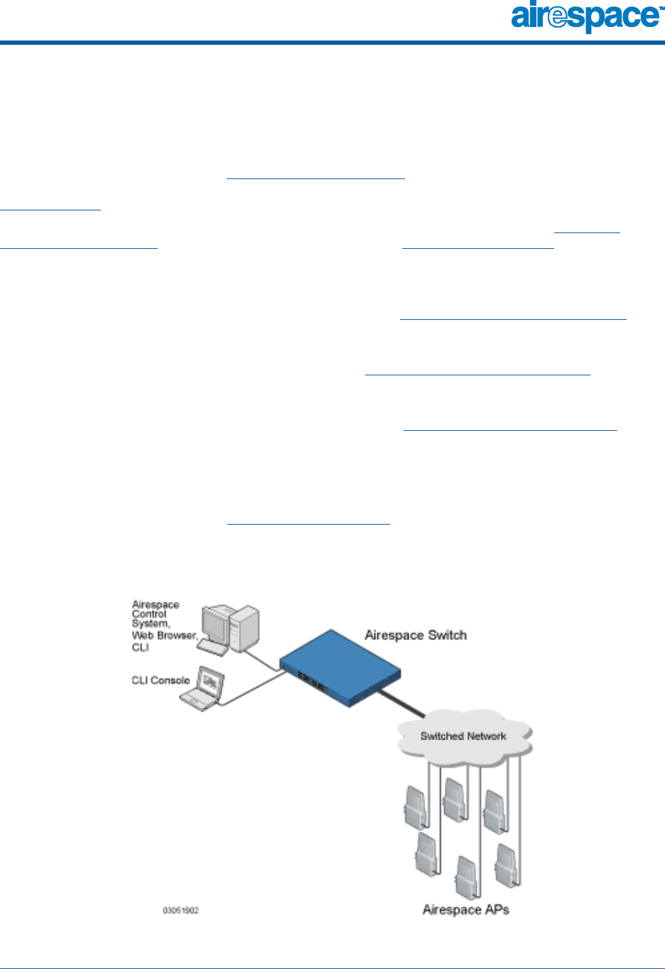
The Airespace System consists of Airespace Wireless Switches and WLAN Appliances (Airespace
Switches and Appliances) and their associated Airespace APs (Airespace Access Points) controlled by
the AireOS, all managed by any or all of the AireOS management interfaces.
•The Airespace Control System Software (ACS Software Server) interface is used to configure
and monitor one or more Airespace Switches and Appliances and associated APs, and has tools
to facilitate large-system monitoring and control. The Airespace Control System Software runs
on any Windows 2000 or XP platform.
•A full-featured CLI (command line interface) can be used to configure and monitor individual
Airespace Switches and Appliances. Refer to the Airespace Command Line Interface section.
•A full-featured Web Browser (HTTP) interface hosted by Airespace Switches and Appliances
running on any platform with a supported Web browser can be used to configure and monitor
individual Airespace Switches and Appliances. See the Airespace Web Browser Interface
section.
•An industry-standard SNMP V1, V2c, and V3 interface can be used with any SNMP-compliant
third-party network management system.
The Airespace solution also allows service providers to incorporate their existing Cisco 1200, Cisco 350
and ORiNOCO 2000 Access Points (Third-Party Access Points) into an expanding Airespace network.
The following figure shows the Airespace System components.
Figure - Airespace System Components in Appliance Mode

10/10/03 About the Airespace System
90-100584-004 Airespace Product Guide 3
Refer to the following for more information:
•AireOS
•Single-Airespace Switch or Appliance Deployments
•Multiple-Airespace Switch and Appliance Deployments
•AireOS Security
•Airespace Wired Security
•AireWave Director Software

10/10/03 Single-Airespace Switch or Appliance Deployments
90-100584-004 Airespace Product Guide 5
Single-Airespace Switch or Appliance DeploymentsSingle-Airespace S witch or Appliance Deploy ments
As described in About the Airespace System, a standalone Airespace Wireless Switch or WLAN
Appliance can support Airespace Access Points (Airespace APs) and third-party APs across multiple
floors and buildings simultaneously, and supports the following features:
•Autodetecting and autoconfiguring Airespace APs as they are added to the network, as
described in AireWave Director Software.
•Full control of Airespace Access Points.
•Full control of associated Third-Party Access Points through the native third-party AP interface,
and real-time control of system-wide WLAN 802.1x security policies.
•Full control of up to 16 Airespace AP and one third-party AP WLAN policy engines, as described
in the Airespace Switch and Appliance Quick Installation Guide.
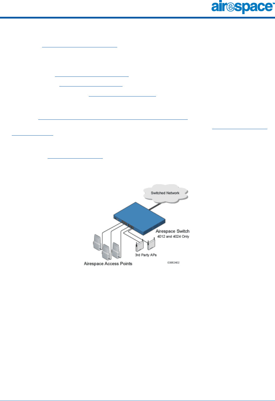
The following figures show typical single Airespace Wireless Switch deployed in Direct Connect Mode
and Appliance Mode.
•In Direct Connect Mode, Airespace APs and third-party APs connect directly to the Model 4012
or 4024 Airespace Wireless Switch front panel, with or without the Airespace Wireless Switch
providing Power Over Ethernet to the APs.
Figure - Typical Single 4012 or 4024 Airespace Wireless Switch Deployed in Direct Connect Mode

10/10/03 Single-Airespace Switch or Appliance Deployments
90-100584-004 Airespace Product Guide 6
•In Appliance Mode, Airespace APs connect to the Model 4012 or 4024 Airespace Wireless Switch
or 4101 or 4102 Airespace WLAN Appliances through the switched network. The switched
network equipment may or may not provide Power Over Ethernet to the Airespace APs.
Note that the 4102 Airespace WLAN Appliance uses two redundant GigE connections to bypass
single network failures. At any given time one of the 4102 Airespace WLAN Appliance GigE
connections is active and the other is passive. Upon a switched network failure, the active
connection becomes passive, and the passive connection becomes active.
Figure - Typical Airespace Wireless Switches and WLAN Appliances Deployed in Appliance Mode
10/10/03 Single-Airespace Switch or Appliance Deployments
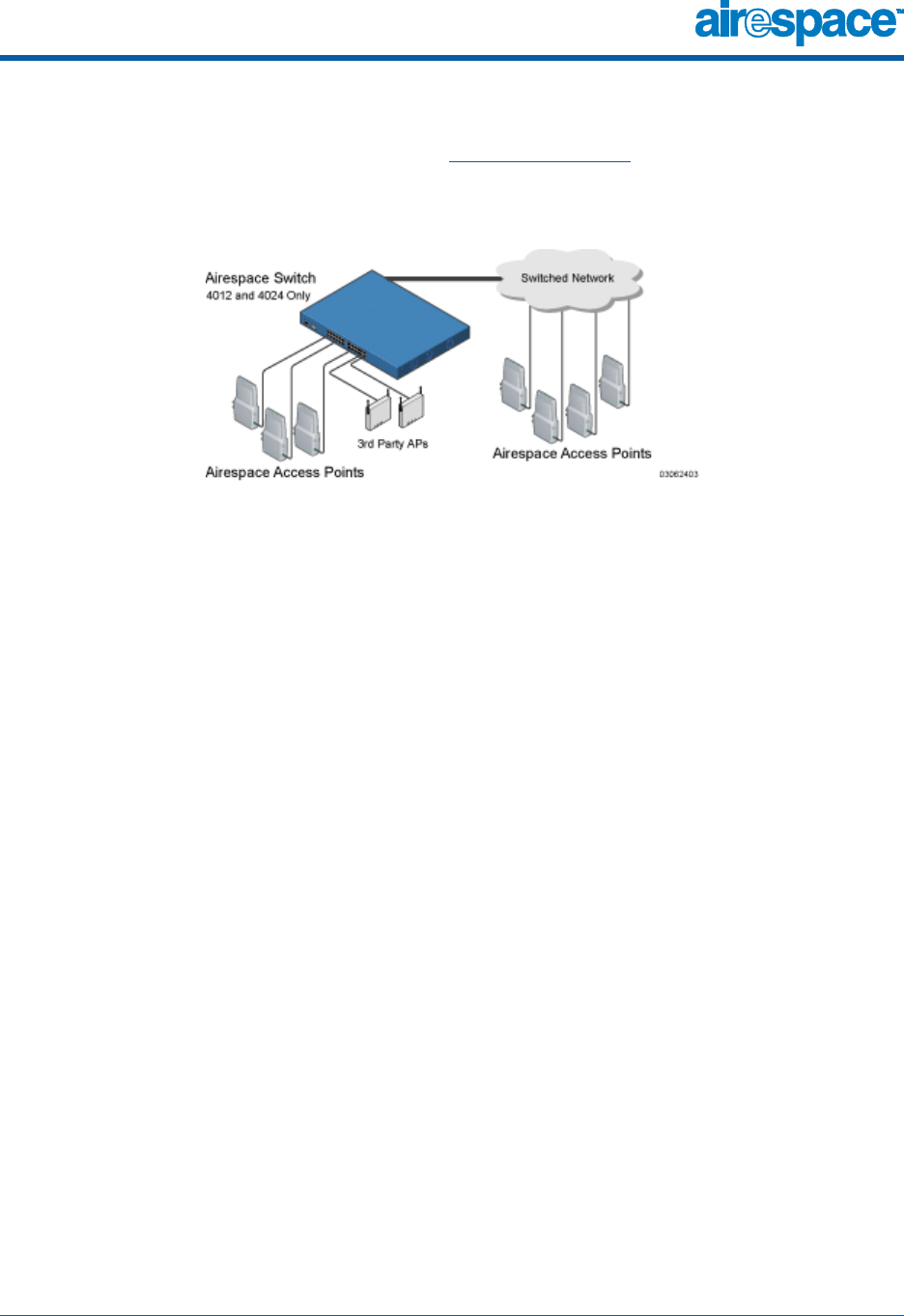
90-100584-004 Airespace Product Guide 7
•In Hybrid Mode, the APs simultaneously connect to the Model 4012 or 4024 Airespace Wireless
Switch in Direct Connect and Appliance Mode, with or without the Airespace Wireless Switch or
the switched network equipment providing Power Over Ethernet to the Airespace APs.
Figure - Typical 4012 or 4024 Single Airespace Wireless Switch Deployed in Hybrid Mode
10/10/03 Multiple-Airespace Switch and Appliance Deployments
90-100584-004 Airespace Product Guide 8
Multiple-Airespace Switch and Appliance DeploymentsMultiple-Airespace S witch and Appliance Deploy ments
Each Airespace Wireless Switch can support Airespace APs and third-party APs across multiple floors
and buildings simultaneously. Similarly, each Airespace WLAN Appliance can support Airespace APs
across multiple floors and buildings simultaneously. However, the Airespace System’s full functionality
is realized when it includes multiple Airespace Switches and Appliances. That is, a multiple-Airespace
Switch and Appliance system has the following additional features over a single-Airespace Switch or
Appliance deployment:
•Autodetecting and autoconfiguring Airespace Switch or Appliance RF parameters as the
Airespace Switches and Appliances are added to the network, as described in AireWave Director
Software.
•Same-Airespace Switch or Appliance (Layer 2) Roaming and Inter-Subnet (Layer 3) Roaming.
•Automatic Airespace Switch and Appliance Failover Protection to any redundant Airespace
Switch or Appliance with unused ports.
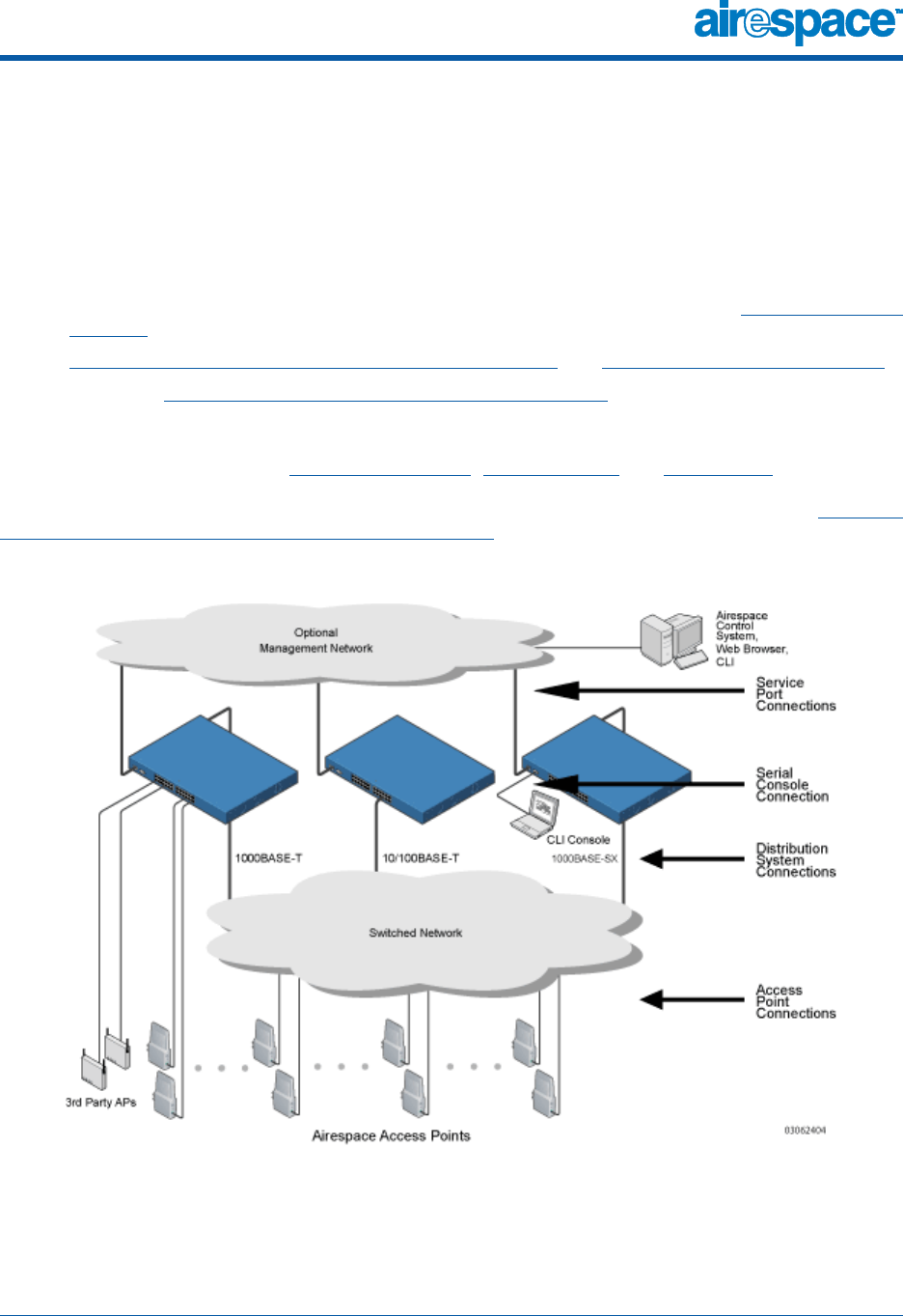
The following figure shows a typical multiple-Airespace Switch and Appliance deployment, with the
Airespace Switch or Appliance in Direct Connect Mode, Appliance Mode and Hybrid Mode. The figure
also shows an optional dedicated Management Network and the three physical connection types
between the switched network and the Airespace Switch or Appliance, as further described in Switched
Network Connection to an Airespace Switch or Appliance.
Figure - Typical Multiple-Airespace Wireless Switch and WLAN Appliance Deployment

10/10/03 AireOS Security
90-100584-004 Airespace Product Guide 9
About AireOS SecurityAireOS Security
AireOS Security bundles Layer 1, Layer 2 and Layer 3 802.11 Access Point security components into a
simple, system-wide policy manager that creates independent security policies for each of up to 16
Airespace WLANs and one third-party WLAN. (Refer to Airespace WLANs.)
One of the barriers that made enterprises avoid deploying 802.11 networks was the inherent weakness
of WEP (Wired Equivalent Privacy) encryption. Because WEP is so insecure, enterprises have been
looking for more secure solutions for business-critical traffic.
The Layer 2 WEP weakness problem can be overcome using more-robust industry-standard security
solutions, such as:
•802.1X dynamic keys with EAP (extended authorization protocol), or
•WPA (Wi-Fi protected access) dynamic keys. The Airespace WPA implementation includes:
-AES (advanced encryption standard),
-TKIP + Michael (temporal key integrity protocol + message integrity code checksum)
dynamic keys, or
-WEP (Wired Equivalent Privacy) keys.
The WEP problem can be further solved using industry-standard Layer 3 security solutions, such as:
•Terminated and pass-through VPNs (virtual private networks), and
•Terminated and pass-through IPSec (IP security) protocols. The terminated Airespace IPSec
implementation includes:
-IKE (internet key exchange),
-DH (Diffie-Hellman) groups, and
-Three optional levels of encryption: DES (ANSI X.3.92 data encryption standard), 3DES
(ANSI X9.52-1998 data encryption standard), or AES/CBC (advanced encryption stan-
dard/cipher block chaining).
The Airespace IPSec implementation also includes industry-standard authentication using:
-MD5 (message digest algorithm), or
-SHA-1 (secure hash algorithm-1).
•The Airespace System supports local and RADIUS MAC (media access control) filtering.
•The Airespace System supports local and RADIUS user/password authentication.
•The Airespace System also uses manual and automated Blacklisting to block access to network
services. In manual Blacklisting, the operator blocks access using client MAC addresses. In
automated Blacklisting, which is always active, the AireOS software automatically blocks access
to network services for an operator-defined period of time when a client fails to authenticate for
a fixed number of consecutive attempts. This can be used to deter brute-force login attacks.
These and other AireOS Security features use industry-standard authorization and authentication
methods to ensure the highest possible security for your business-critical wireless LAN traffic.
For information about Airespace wired security, refer to Airespace Wired Security.

10/10/03 Airespace Wired Security
90-100584-004 Airespace Product Guide 10
About Airespace Wired SecurityAirespace Wired Security
Many traditional Access Point vendors concentrate on security for the Wireless interface similar to that
described in the AireOS Security section. However, for secure Airespace Switch and Appli-
ance-to-Management Interfaces (Airespace Control System Software, Airespace Web Browser
Interface, and Airespace Command Line Interface), Airespace Switch and Appliance-to-AP, and
inter-Airespace Switch and Appliance communications during device management and Client Roaming,
the AireOS includes built-in security.
The AireOS automatically loads signed X.509 certificates into each Airespace Switch and Appliance and
Airespace AP to authenticate IPSec tunnels between devices. These IPSec tunnels ensure secure
communications for mobility and management.
Airespace Switches and Appliances and Airespace APs also use the signed certificates to verify down-
loaded code before it is loaded, ensuring that hackers do not download malicious code into any
Airespace Wireless Switch, Airespace WLAN Appliance or Airespace AP.
For information about Airespace wireless security, refer to AireOS Security.

10/10/03 AireWave Director Software
90-100584-004 Airespace Product Guide 11
About AireWave Director SoftwareAire Wave Director Software
Airespace, Inc. is the only company to offer the powerful, comprehensive, and dynamic AireWave
Director Software solution to the 802.11 market. The AireWave Director Software allows Airespace
Switches and Appliances to continually monitor their associated Airespace APs for the following
information:
•Traffic Load -- How much total bandwidth is used for transmitting and receiving traffic. This
allows WLAN managers to track network growth and plan network growth ahead of client
demand.
•Interference -- How much traffic is coming from other 802.11 sources.
•Noise -- How much non-802.11 noise is interfering with the currently-assigned channel.
•Coverage -- Received Signal Strength (RSSI) and Signal to Noise Ratio (SNR) for all clients.
•Nearby APs.
Using the collected information, the AireWave Director Software can periodically reconfigure the 802.11
RF network within operator-defined limits for best efficiency. To do this, AireWave Director Software:
•Dynamically reassign channels to increase capacity and performance, both within the same
Airespace Switch or Appliance and across multiple Airespace Switches and Appliances.
•Adjust the transmit power to balance coverage and capacity, both within the same Airespace
Switch or Appliance and across multiple Airespace Switches and Appliances.
•Allows the operator to assign nearby Airespace APs into groups to streamline AireWave Director
Software algorithm processing.
•As new clients associate, they are load balanced across grouped Airespace APs reporting to
each Airespace Switch or Appliance. This is particularly important when many clients converge
in one spot (such as a conference room or auditorium), because AireWave Director Software
can automatically force some subscribers to associate with nearby APs, allowing higher
throughput for all clients.
•Automatically detect and configure new Airespace APs as they are added to the network. The
AireWave Director Software automatically adjusts nearby Airespace APs to accommodate the
increased coverage and capacity.
•Automatically detect and configure new Airespace Switches and Appliances as they are added
to the network. The AireWave Director Software automatically distributes associated Airespace
APs to maximize coverage and capacity.
•Detect and report coverage holes, where clients consistently connect to an Airespace AP at a
very low signal strength.
•Automatically define Airespace Switch and Appliance Groups within operator-defined Mobility
Groups.
The AireWave Director Software solution thus allows the operator to avoid the costs of laborious histor-
ical data interpretation and individual Access Point reconfiguration. The power control features of
AireWave Director Software ensure client satisfaction, and the coverage hole detection feature can alert
the operator to the need for an additional (or relocated) Airespace AP.
Note that the AireWave Director Software uses separate monitoring and control for each of the
deployed networks: 802.11a and 802.11b/802.11g. Also note that the AireWave Director Software is
automatically enabled, but can be customized or disabled for individual Airespace APs.
Finally, for operators requiring easy manual configuration, the AireOS can recommend the best radio
settings, and then assign them on operator command.

10/10/03 AireWave Director Software
90-100584-004 Airespace Product Guide 12
The AireWave Director Software controls produce a network that has optimal capacity, performance,
and reliability. The AireWave Director Software functions also free the operator from having to continu-
ally monitor the network for noise and interference problems, which can be transient and difficult to
troubleshoot. Finally, the AireWave Director Software controls ensure that clients enjoy a seamless,
trouble-free connection through the Airespace 802.11 network.

10/10/03 Master Airespace Switch or Appliance
90-100584-004 Airespace Product Guide 13
About the Master Airespace Switch or ApplianceMaster A irespace Switch or Applia nce
When you are adding Airespace APs to a Multiple-Airespace Switch and Appliance Deployments network
configured in Appliance Mode, it is convenient to have all of the Airespace APs associate with one
Master Airespace Wireless Switch or WLAN Appliance on the same subnet. That way, the operator does
not have to log into multiple Airespace Switches and Appliances to find out which Airespace Switch or
Appliance newly-added Airespace APs associated with.
One Airespace Switch or Appliance in each subnet can be assigned as the Master Airespace Switch or
Appliance while adding Airespace APs. As long as a Master Airespace Switch or Appliance is active on
the same subnet, all new Airespace APs without a Primary Airespace Switch or Appliance assigned auto-
matically attempt to associate with the Master Airespace Switch or Appliance. This process is described
in Airespace Switch and Appliance Failover Protection.
The operator can monitor the Master Airespace Switch or Appliance using the Airespace Web Browser
Interface or the Airespace Control System Software GUI, and watch as Airespace APs associate with the
Master Airespace Switch or Appliance. The operator can then verify Airespace AP configuration and
assign a Primary Airespace Switch or Appliance to the Airespace AP, and reboot the Airespace AP so it
reassociates with its Primary Airespace Switch or Appliance.
Note: Airespace APs without a Primary Airespace Switch or Appliance assigned always search
for a Master Airespace Switch or Appliance first upon reboot. After adding Airespace APs
through the Master Airespace Switch or Appliance, assign a Primary Airespace Switch or
Appliance to each Airespace AP.
Airespace recommends that you disable the Master Airespace Switch or Appliance setting on
all Airespace Switches and Appliances after initial configuration.

10/10/03 Primary Airespace Switch or Appliance
90-100584-004 Airespace Product Guide 14
About the Primary Airespace Switch or AppliancePrimary Airespace Switch or Appliance
In Multiple-Airespace Switch and Appliance Deployments networks, Airespace APs can associate with
any Airespace Wireless Switch or WLAN Appliance in Appliance Mode on the same subnet. To ensure
that each Airespace AP associates with a particular Airespace Switch or Appliance, the operator can
assign a Primary Airespace Switch or Appliance to the Airespace AP.
When an Airespace AP is added to a switched network, it looks for its Primary Airespace Switch or
Appliance first, then a Master Airespace Switch or Appliance, then the least-loaded Airespace Switch or
Appliance with available primary and secondary ports. Refer to Airespace Switch and Appliance Failover
Protection for more information.

10/10/03 Client Roaming
90-100584-004 Airespace Product Guide 15
About Client RoamingClient Roaming
The Airespace System supports seamless client roaming across APs managed by the same Airespace
Wireless Switch or WLAN Appliance, between Airespace Switches and Appliances on the same subnet,
and across Airespace Switches and Appliances on different subnets. The following chapters describes
the three modes of roaming supported by the Airespace System.
Same-Airespace Switch or Appliance (Layer 2) RoamingSame-Airespace Switch or Appliance (L ayer 2) Roaming
Each Airespace Switch and Appliance supports same-Airespace Switch or Appliance client roaming
across Airespace APs and third-party APs managed by the same Airespace Switch or Appliance, whether
in Direct Connect Mode, Appliance Mode or Hybrid Mode. This roaming is transparent to the client, as
the session is sustained and the client continues using the same DHCP-assigned or client-assigned IP
address. Same-Airespace Switch or Appliance roaming is supported in Single-Airespace Switch or
Appliance Deployments and Multiple-Airespace Switch and Appliance Deployments.
Inter-Airespace Switch and Appliance (Layer 2) RoamingInter-Airespace Switch and Appliance (Layer 2) Roaming
Similarly, in Multiple-Airespace Switch and Appliance Deployments, the Airespace System supports
client roaming across Airespace APs and third-party APs managed by Airespace Switches and Appli-
ances on the same subnet. This roaming is also transparent to the client, as the session is sustained
and a tunnel between Airespace Switches and Appliances allows the client to continue using the same
DHCP-assigned or client-assigned IP address as long as the session remains active. Note that the
tunnel is torn down when the client sends a DHCP Discover with a 0.0.0.0 client IP address or a
169.254.*.* client auto-IP address, or when the operator-set session timeout is exceeded.
Inter-Subnet (Layer 3) RoamingInter-Subnet (Layer 3) Roaming
Similarly, in Multiple-Airespace Switch and Appliance Deployments, the Airespace System supports
client roaming across Airespace APs and third-party APs managed by Airespace Switch and Appliance
on different subnets. This roaming is transparent to the client, because the session is sustained and a
tunnel between the Airespace Switches and Appliances allows the client to continue using the same
DHCP-assigned or client-assigned IP address as long as the session remains active. Note that the
tunnel is torn down when the client sends a DHCP Discover with a 0.0.0.0 client IP address or a
169.254.*.* client auto-IP address, or when the operator-set session timeout is exceeded.
Special Case: Voice Over IP Telephone RoamingSpecial Case: Voice Over IP Telephone Roam ing
802.11 VoIP telephones actively seek out associations with the strongest RF signal to ensure best
Quality of Service (QoS) and maximum throughput. The minimum VoIP telephone requirement of
20 millisecond or shorter latency time for the roaming handover is easily met by the Airespace System,
which has an average handover latency of nine or fewer milliseconds.
This short latency period is controlled by Airespace Switches and Appliances, rather than allowing inde-
pendent APs to negotiate roaming handovers.
The Airespace System supports 802.11 VoIP telephone roaming across Airespace APs and third-party
APs managed by Airespace Switches and Appliances on different subnets. This roaming is transparent
to the VoIP telephone, because the session is sustained and a tunnel between Airespace Switches and
Appliances allows the VoIP telephone to continue using the same DHCP-assigned IP address as long as
the session remains active. Note that the tunnel is torn down when the VoIP telephone sends a DHCP
Discover with a 0.0.0.0 VoIP telephone IP address or a 169.254.*.* VoIP telephone auto-IP address, or
when the operator-set session timeout is exceeded.

10/10/03 External DHCP Servers
90-100584-004 Airespace Product Guide 16
About External DHCP ServersExtern al DHCP Se rvers
The AireOS is designed to operate as a ‘DHCP Proxy’ with industry-standard external DHCP Servers that
support DHCP Relay. This means that each Airespace Wireless Switch or WLAN Appliance appears as a
DHCP Relay agent to the DHCP Server. This also means that the Airespace Switch or Appliance appears
as a DHCP Server to wireless clients at the virtual IP address.
Because the Airespace Switch or Appliance controls the client IP address obtained from a DHCP Server,
it maintains the same IP address for that client during same-Airespace Switch or Appliance,
inter-Airespace Switch and Appliance, and inter-subnet Client Roaming.
Per-WLAN AssignmentPer-WLAN Assignment
All Airespace WLANs can be configured to use the same or different DHCP Servers, or no DHCP Server.
This allows operators considerable flexibility in configuring their Wireless LANs, as further described in
the Airespace WLANs section.
Note that Airespace WLANs that support Management over Wireless must allow the management
clients to obtain an IP address from a DHCP Server.
Security ConsiderationsSecurity Considera tions
For enhanced security, it is recommended that operators require all clients to obtain their IP addresses
from a DHCP server. To enforce this requirement, all Airespace WLANs can be configured with a ‘DHCP
Required’ setting and a valid DHCP Server IP address, which disallows client static IP addresses. If a
client associating with a WLAN with ‘DHCP Required’ set does not obtain its IP address from the desig-
nated DHCP Server, it is not allowed access to any network services.
If slightly less security is tolerable, operators can create Airespace WLANs with ‘DHCP Required’
disabled and a valid DHCP Server IP address. Clients then have the option of using a static IP address
or obtaining an IP address from the designated DHCP Server.
Operators are also allowed to create separate Airespace WLANs with ‘DHCP Required’ disabled and a
DHCP Server IP address of 0.0.0.0. These WLANs drop all DHCP requests and force clients to use a
static IP address. Note that these WLANs do not support Management over Wireless.
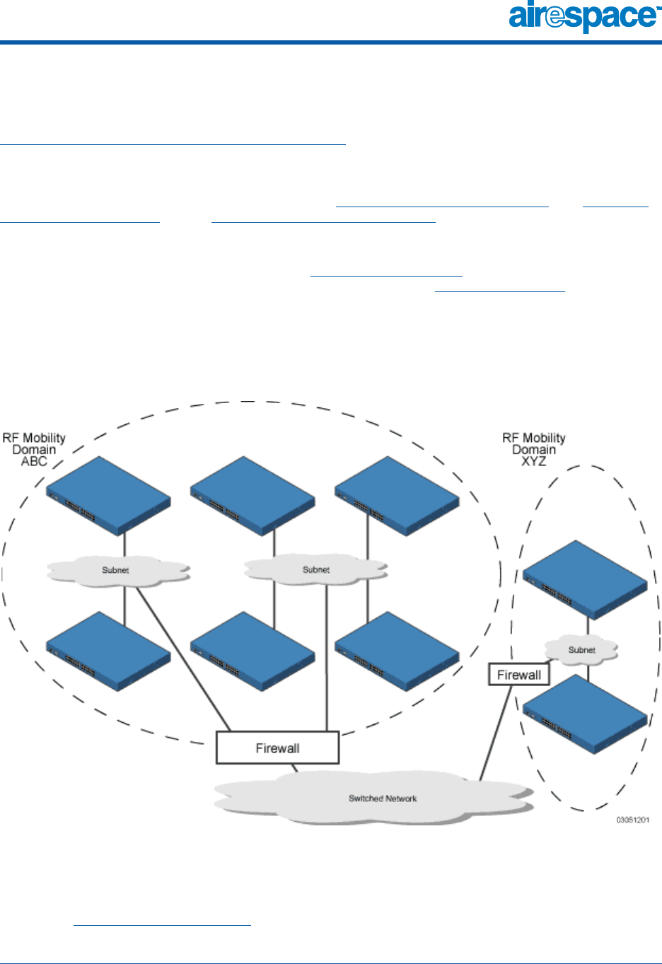
10/10/03 Airespace Mobility Group
90-100584-004 Airespace Product Guide 17
About Airespace Mobility GroupsAirespace M obility Group
Airespace System operators can define Mobility Groups to allow client roaming across groups of
Airespace Wireless Switches and WLAN Appliances. Because the Airespace Switches and Appliances in
Multiple-Airespace Switch and Appliance Deployments can detect each other across the switched
network and over the air, it is important that each enterprise, institution, and wireless internet service
provider isolate their Airespace Switches and Appliances. The AireOS makes it easy for operators to
create this isolation by allowing them to assign a Mobility Group Name to their Airespace Switches and
Appliances. This assignment can be made using the Airespace Web Browser Interface, the Airespace
Control System Software, or the Airespace Command Line Interface.
The following figure shows the results of creating Mobility Group Names for two groups of Airespace
Switches and Appliances. The Airespace Switches and Appliances in the ABC Mobility Group recognize
and communicate with each other through their Airespace Access Points and through their shared
subnets, but the ABC Mobility Group tags the XYZ Airespace APs as Rogue Access Points. Likewise, the
Airespace Switches and Appliances in the XYZ Mobility Group do not recognize or communicate with the
Airespace Switches and Appliances in the ABC Mobility Group. This feature ensures Mobility Group
isolation across the switched network.
Figure - Typical Airespace Mobility Group Name Application
The Airespace Mobility Group feature can also be used to limit roaming between different floors, build-
ings, or campuses in the same enterprise by assigning different Mobility Group names to different
Airespace Switches and Appliances within the same wireless network.
If enabled, AireWave Director Software operation is constrained within each Airespace Mobility Group.

10/10/03 Airespace Mobility Group
90-100584-004 Airespace Product Guide 18
Note: Because the Airespace Switches and Appliances talk to each other when they are in the
same mobility group, Airespace recommends that operators do not add physically-separated
Airespace Switches and Appliances to the same static mobility group to avoid unnecessary
traffic on the switched network.
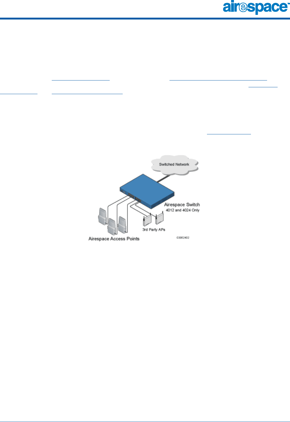
10/10/03 Airespace Wired Connections
90-100584-004 Airespace Product Guide 19
About Airespace Wired ConnectionsAirespace Wired Connections
The Airespace System components communicate with each other using industry-standard Ethernet
cables and connectors. The following sections contain details of the Airespace wired connections.
Between Airespace Wireless Switches and APsBetween Airespace Wireless Switches and APs
When operated in Direct Connect Mode, the 4012 and 4024 Airespace Switches and Appliances uses
standard 802.3 CAT-5 (Category 5) or higher twisted-pair Ethernet cables to connect to Airespace
Access Points and Third-Party Access Points. The CAT-5 cable is rated to carry 100 Mbps (recom-
mended for 802.11a, 802.11a/b, 802.11a/g or 802.11a/b/g installations) or 10 Mbps (only
recommended for low-bandwidth applications and 802.11b-only installations).
The 4012 and 4024 Airespace Wireless Switches connect to the switched network using a copper 10/
100Base-T cable or a copper or fiber-optic GigE cable.
Note that the 4101 and 4102 Airespace WLAN Appliances operate only in Appliance Mode, and do not
connect directly to any Access Points.
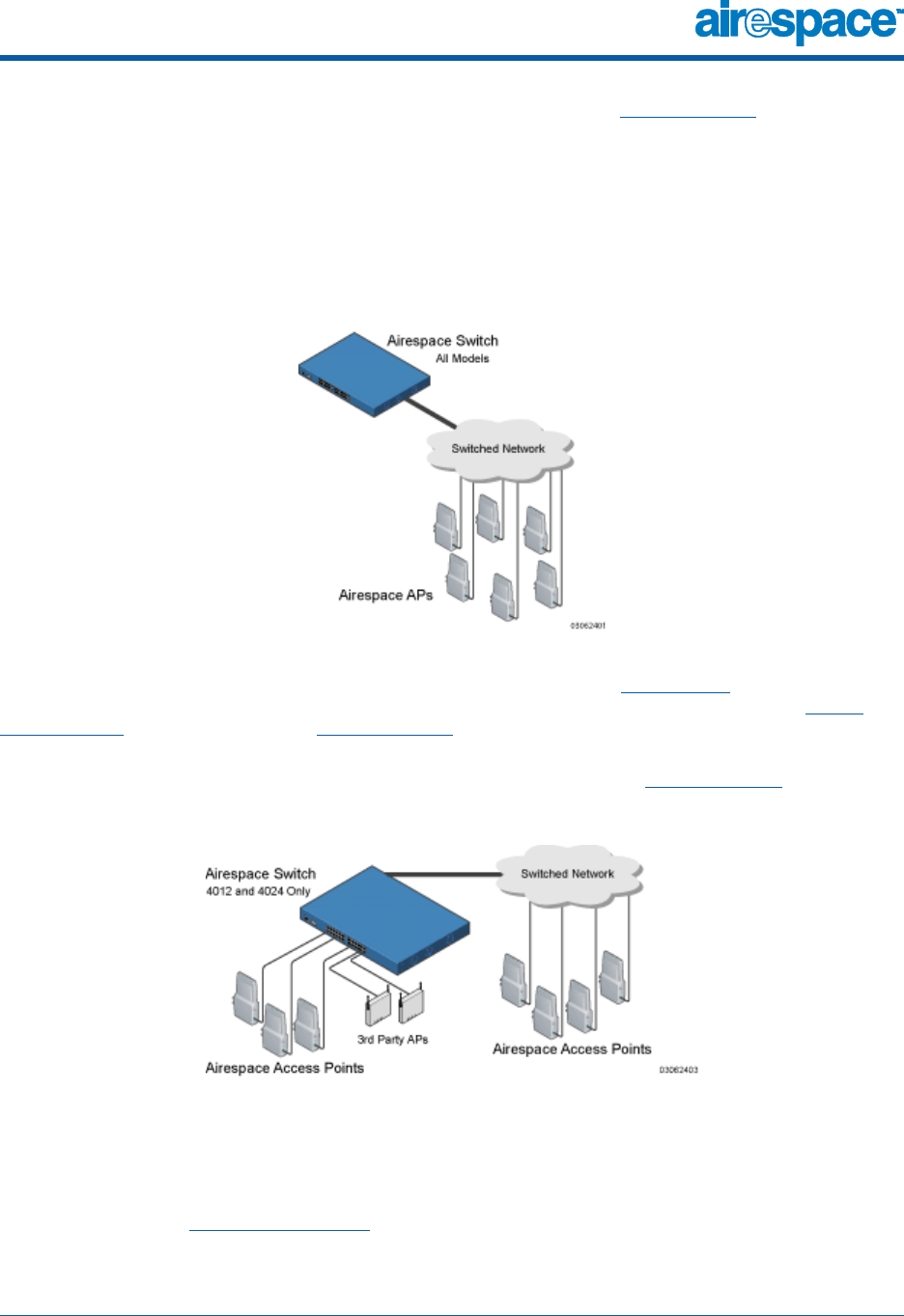
10/10/03 Airespace Wired Connections
90-100584-004 Airespace Product Guide 20
When the Airespace Wireless Switch or WLAN Appliance is operated in Appliance Mode, the Airespace
APs communicate with the Airespace Switch or Appliance through the switched network. The 4012 and
4024 Airespace Wireless Switches connect to the switched network using a copper 10/100Base-T cable
or a copper or fiber-optic GigE cable.
The 4101 Airespace WLAN Appliance connects to the switched network using a fiber-optic GigE cable.
The 4102 Airespace WLAN Appliance connects to the switched network using two fiber-optic GigE
cables: two redundant GigE connections to bypass single network failures. At any given time one of the
4102 Airespace WLAN Appliance GigE connections is active and the other is passive. Upon a switched
network failure, the active connection becomes passive, and the passive connection becomes active.
When the 4012 and 4024 Airespace Wireless Switches are operated in Hybrid Mode, some Airespace
APs and third-party APs use the CAT-5 cable to connect to the Airespace Wireless Switch in Direct
Connect Mode and some connect in Appliance Mode. The Airespace Wireless Switch connects to the
switched network using a copper 10/100Base-T cable or a copper or fiber-optic GigE cable.
Note that the 4101 and 4102 Airespace WLAN Appliances only operate in Appliance Mode, and do not
connect directly to any Access Points.
Standard CAT-5 cable supports a 100 m (328 ft.) run between the Airespace APs and the Airespace
Wireless Switch. This allows a single Airespace Wireless Switch to serve Airespace APs in multiple
buildings and/or floors in a single building.
The standard CAT-5 cable can also be used to conduct power for the Airespace APs from a network
device equipped with Power Over Ethernet (PoE) capability. This power distribution plan can be used to
reduce the cost of individual AP power supplies and related cabling.

10/10/03 Airespace Wired Connections
90-100584-004 Airespace Product Guide 21
Between Airespace Switches and Appliances and Other Network DevicesBetween Airespace Switches and Appliances and Other Network Devices
The 4012 and 4024 Airespace Wireless Switches communicate with other Airespace Wireless Switches
and WLAN Appliances or network devices through standard CAT-5 cable connected to front-panel
Port 1, which supports up to 100 Mbps, or through Gigabit Ethernet (or GigE) cabling, which supports
up to 1 Gbps (1,000 Mbps).
The 4101 Airespace WLAN Appliance connects to the switched network using a fiber-optic GigE cable.
The 4102 Airespace WLAN Appliance connects to the switched network using two fiber-optic GigE
cables: two redundant GigE connections to bypass single network failures. At any given time one of the
4102 Airespace WLAN Appliance GigE connections is active and the other is passive. Upon a switched
network failure, the active connection becomes passive, and the passive connection becomes active.

10/10/03 Airespace WLANs
90-100584-004 Airespace Product Guide 22
About Airespace WLANsAires pace WLANs
The Airespace System can control up to 16 Wireless LANs for Airespace Access Points plus one WLAN
for Third-Party Access Points. Each WLAN has a separate WLAN ID (1 through 17), a separate WLAN
SSID (WLAN Name), and can be assigned unique security policies. A separate WLAN 17 can be created
for Third-Party Access Points connected to a Model 4012 or 4024 Airespace Wireless Switch front panel
in Direct Connect Mode.
The Airespace APs broadcast all active WLAN SSIDs and enforce the policies defined for each WLAN,
while the operator-managed third-party APs broadcast the third-party AP SSID and enforce the oper-
ator-defined policies.
Note that many enterprises use different WLANs to separate traffic for different sections or
departments.
If Mgmt Via Wireless is enabled on a non-IPSec WLAN, the Airespace System operator can manage the
System across the enabled WLAN using CLI and Telnet (Airespace Command Line Interface), http/https
(Airespace Web Browser Interface), and SNMP (Airespace Control System Software).
To configure the Airespace WLANs, refer to Configuring WLANs.

10/10/03 Transferring Files
90-100584-004 Airespace Product Guide 23
About File TransfersTran sferring Files
The Airespace System operator can upload and download code, configuration, and certificate files to
and from an Airespace Wireless Switch or WLAN Appliance using Airespace CLI commands, Airespace
Web Browser Interface commands, or Airespace Control System Software (ACS Software) commands.
•To use CLI commands, refer to Transferring Files To and From an Airespace Switch or Appliance
•To use the Web Browser Interface, go to Using the Airespace Web Browser Interface
•To use ACS Software Server commands, continue with Using the Airespace Control System
Software
10/10/03 Power Over Ethernet
90-100584-004 Airespace Product Guide 24
About Power Over EthernetPower Over Ethernet
Airespace Wireless Switches and WLAN Appliances and Airespace APs supports 802.3af-compliant
Power over Ethernet (PoE), which can reduce the cost of discrete power supplies, additional wiring,
conduits, outlets, and installer time. PoE also frees installers from having to mount Airespace Access
Points or other powered equipment near AC outlets, providing greater flexibility in positioning Airespace
APs for maximum coverage.
When you are using PoE, the installer runs a single CAT-5 cable from each Airespace AP to the
PoE-equipped Airespace Switches and Appliances or other network element, or to a PoE power hub.
When the PoE equipment determines that the Airespace AP is PoE-enabled, it sends 48 VDC over the
unused pairs in the Ethernet cable to power the Airespace AP.
Note: Airespace APs can receive power from the Airespace Wireless Switch or any other
network device conforming to the IEEE 802.3af standard.
Note: Each Airespace AP can also receive power from an Airespace AP External Power
Converter.
The Airespace Wireless Switch can be ordered with or without PoE, as required. It can be ordered with
internal PoE or an external third-party PoE hub. Contact Airespace for recommended external PoE hubs.

10/10/03 Airespace Switches and Appliances
90-100584-004 Airespace Product Guide 25
About Airespace Switches and AppliancesAirespace Switches and Appliances
The Airespace Wireless Switch and WLAN Appliance are enterprise-class high-performance wireless
switching platforms that support 802.11a and 802.11b/802.11g (802.11b/g) protocols. They operate
under control of the AireOS, and includes wire-speed Layer 2 switching designed to support the
Airespace Switched Architecture, which results in an Airespace System that can automatically adjust to
real-time changes in the 802.11 RF environment. The Airespace Switches and Appliances are built
around high-performance network and security hardware, resulting in highly reliable 802.11 enterprise
networks with unparalleled security.
This section includes the following:
•4012 and 4024 Airespace Wireless Switch Models
•4101 and 4102 Airespace WLAN Appliance Models
•Airespace Switch and Appliance Features
•Airespace Switch and Appliance Model Numbers
•Direct Connect Mode
•Appliance Mode
•Hybrid Mode
•Distribution System Port
•Service (Management) Port
•Airespace Switch and Appliance Memory
•Startup Wizard
•Airespace Switch and Appliance Failover Protection
•Switched Network Connection to an Airespace Switch or Appliance
•Enhanced Security Module
•Airespace Wired Connections
•Airespace WLANs
•Transferring Files
•Configuring the Airespace Switch or Appliance
•Transferring Files To and From an Airespace Switch or Appliance
•Updating the AireOS Software
•Clearing Configurations
•Resetting the Airespace Switch or Appliance
•Airespace Switch and Appliance Quick Installation Guide
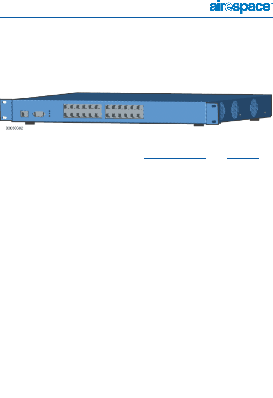
10/10/03 4012 and 4024 Airespace Wireless Switch Models
90-100584-004 Airespace Product Guide 26
4012 and 4024 Airespace Wireless Switch Models4012 and 4024 Airespace Wireless Switch Models
About the Airespace System gives a comprehensive overview of the Airespace System and the place of
the Airespace Wireless Switches and WLAN Appliances in that system. The following figure shows the
4024 Airespace Wireless Switch. The 4012 Airespace Wireless Switch is similar to the 4024, but has 12
front-panel RJ-45 jacks instead of 24.
Figure - 4024 Airespace Wireless Switch
The 4012 and 4024 Airespace Wireless Switches are one-unit high 802.11 Wireless Switches that
communicate directly (Direct Connect Mode), indirectly (Appliance Mode), or both (Hybrid Mode) with
up to 24 (Model 4024) or 12 (Model 4012) associated Airespace Access Points and/or Third-Party
Access Points. The 4012 and 4024 Airespace Wireless Switches can be factory- or field-equipped with
an Enhanced Security Module (Crypto Card) to support VPN, IPSec and other processor-intensive tasks,
and with one 1000Base-T (copper) or 1000Base-SX (fiber-optic) Network Adaptor Module to allow the
Airespace Wireless Switch to communicate with the switched network at GigE (Gigabit Ethernet)
speeds.
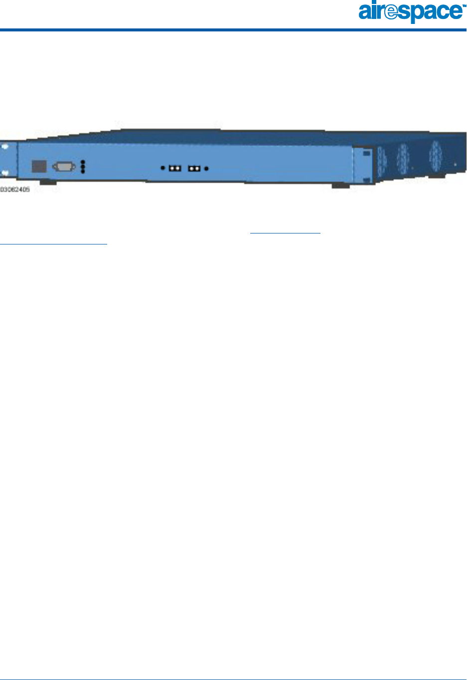
10/10/03 4101 and 4102 Airespace WLAN Appliance Models
90-100584-004 Airespace Product Guide 27
4101 and 4102 Airespace WLAN Appliance Models4101 and 4102 Airespace WLAN Applianc e Models
The following figure shows the 4102 Airespace WLAN Appliance. The 4101 Airespace WLAN Appliance is
similar to the 4102, but has one front-panel SX/LC jack instead of two.
Figure - 4102 Airespace WLAN Appliance
The 4101 and 4102 Airespace WLAN Appliances are one-unit high 802.11 Wireless Appliances that
communicate indirectly through the switched network (Appliance Mode) with up to 36 associated
Airespace Access Points. The 4101 and 4102 Airespace WLAN Appliances can be factory-ordered with
an Enhanced Security Module (Crypto Card) to support VPN, IPSec and other processor-intensive tasks,
and with one (4101) or two (4102) 1000Base-SX network connectors to allow the Airespace WLAN
Appliance to communicate with the switched network at GigE (Gigabit Ethernet) speeds.
The two redundant GigE connections on the 4102 allow the Airespace WLAN Appliance to bypass single
network failures. At any given time one of the 4102 Airespace WLAN Appliance GigE connections is
active and the other is passive. Upon a switched network failure, the active connection becomes
passive, and the passive connection becomes active.

10/10/03 Airespace Switch and Appliance Features
90-100584-004 Airespace Product Guide 28
Airespace Switch and Appliance FeaturesAirespace Swi tch and Appliance Features
Because Airespace Wireless Switches and WLAN Appliances perform most of the processes normally
performed by SOHO Access Points, it can reduce the amount of inter-AP traffic on the wired backbone
network when used in Direct Connect Mode. When operated in Appliance Mode, Airespace Switches and
Appliances connect to the associated Airespace APs through the switched network. When deployed in
Hybrid Mode, Airespace Wireless Switches simultaneously communicate with their associated APs
through their front-panel ports as well as through the switched network.
Note that the 4101 and 4102 Airespace WLAN Appliances are designed to operate exclusively in
Appliance Mode. As such, they are limited to controlling Airespace Access Points. However the operator
can use Airespace Control System Software as a gateway to independently detect and manage
Third-Party Access Points.
After each Airespace Switch or Appliance is installed and configured, the AireOS AireWave Director
Software is activated, and the AireOS manages and controls associated Airespace APs and/or
third-party APs (Direct Connect Mode only), with information about their relative positions, IP
Addresses, and MAC addresses. This information allows all Airespace Switches and Appliances within
each Airespace Mobility Group to constantly monitor and dynamically adjust the RF environment, maxi-
mizing performance, minimizing interference, and distributing the client load.
When operated in Direct Connect Mode, the 4012 or 4024 Airespace Wireless Switches communicate
directly with Airespace APs and third-party APs via 10/100Base-T Ethernet cables.
When operated in Appliance Mode, the 4012 and 4024 Airespace Wireless Switches communicate with
Airespace APs via 10/100Base-T Ethernet or 1000Base-T or 1000Base-SX cables through the switched
network.
When operated in Appliance Mode, the 4101 and 4102 Airespace WLAN Appliances communicate with
Airespace APs via 1000Base-SX cables through the switched network. Note that the 4102 Airespace
WLAN Appliance uses two redundant GigE connections to bypass single network failures. At any given
time one of the 4102 Airespace WLAN Appliance GigE connections is active and the other is passive.
Upon a switched network failure, the active connection becomes passive, and the passive connection
becomes active.
The 4012 or 4024 Airespace Wireless Switches communicate with switched network via front-panel 10/
100Base-T Ethernet Port 1, or via a 1000Base-T or 1000Base-SX Network Port. The 4101 or 4102
Airespace WLAN Appliances communicate with switched network via one (4101) or two (4102)
1000Base-SX Network Ports: the 4102 Airespace WLAN Appliance uses two redundant GigE connec-
tions to bypass single network failures.
Regardless of operating mode, the network operator can control the Airespace Switches and Appliances
with the following AireOS management interfaces:
•With optional Airespace Control System Software (ACS Software Server) inband or out-of-band
via an 10/100Base-T Service/Management Port (recommended), or via the switched network.
•With the built-in Airespace Command Line Interface via a serial RS232-C Console Port (direct
connection), or via the switched network (Telnet connection).
•With the built-in Airespace Web Browser Interface via a dedicated 10/100Base-T Service/
Management Port (recommended), or via the switched network, using either http or https (http
+ SSL).
Refer to the following for more information about the Airespace Switches and Appliances:
•Airespace Switch and Appliance Model Numbers
•Direct Connect Mode
•Appliance Mode
•Hybrid Mode
10/10/03 Airespace Switch and Appliance Features
90-100584-004 Airespace Product Guide 29
•Distribution System Port
•Service (Management) Port
•Airespace Switch and Appliance Memory
•Startup Wizard
•Airespace Switch and Appliance Failover Protection
•Switched Network Connection to an Airespace Switch or Appliance
•Enhanced Security Module
•Airespace Access Points
•Airespace WLANs
•Transferring Files
•Configuring the Airespace Switch or Appliance
•Transferring Files To and From an Airespace Switch or Appliance
•Updating the AireOS Software
•Clearing Configurations
•Resetting the Airespace Switch or Appliance
•Airespace Switch and Appliance Quick Installation Guide

10/10/03 Airespace Switch and Appliance Model Numbers
90-100584-004 Airespace Product Guide 30
Airespace Switch and Appliance Model NumbersAirespac e Switch and Appliance M odel Numbers
The Airespace Wireless Switch and WLAN Appliance models are as follows:
•AS-4012 - Twelve-Port Airespace Wireless Switch with an optional 1000Base-T or
1000Base-SX/LC Network Adapter, used in Direct Connect Mode, Appliance Mode, and Hybrid
Mode.
•AS-4024 - 24-Port Airespace Wireless Switch with an optional 1000Base-T or 1000Base-SX/LC
Network Adapter, used in Direct Connect Mode, Appliance Mode, and Hybrid Mode.
•AS-4012-POE - Twelve-Port Airespace Wireless Switch with built-in PoE Hub and an optional
1000Base-T or 1000Base-SX/LP Network Adapter, used in Direct Connect Mode, Appliance
Mode, and Hybrid Mode.
•AS-4012-POE - 24-Port Airespace Wireless Switch with built-in PoE Hub and an optional
1000Base-T or 1000Base-SX/LC Network Adapter, used in Direct Connect Mode, Appliance
Mode, and Hybrid Mode.
•AS-4101 - 36-Port Airespace WLAN Appliance with one 1000Base-SX/LC Network Adapter, used
only in Appliance Mode.
•AS-4102 - 36-Port Airespace WLAN Appliance with one 1000Base-SX/LC Network Adapter, used
only in Appliance Mode. The 4102 Airespace WLAN Appliance uses two redundant GigE connec-
tions to bypass single network failures. That is, at any given time one of the 4102 Airespace
WLAN Appliance GigE connections is active and the other is passive. Upon a switched network
failure, the active connection becomes passive, and the passive connection becomes active.
Note that all Airespace Switch and Appliance models come from the factory with 19-inch EIA equipment
rack flush-mount ears and tabletop mounting feet.
The following upgrade modules are also available:
•AS-Switch-ESM - Enhanced Security Module: Supports VPN, IPSec and other
processor-intensive security options. This is a factory-orderable option for all Airespace
Switches and Appliances, and is a field-installable option for the 4012 and 4024 Airespace
Wireless Switches.
•AS-Switch-GT - 1000Base-T Network Adapter Module: Supports 1000Base-T connections to the
switched network. This is a factory-orderable and field-installable option for 4012 and 4024
Airespace Wireless Switches.
•AS-Switch-GSX - 1000Base-SX Network Adapter Module: Supports 1000Base-SX connections
to the switched network. This is a factory-orderable and field-installable option for 4012 and
4024 Airespace Wireless Switches, and is factory-installed in 4101 and 4102 Airespace WLAN
Appliances.
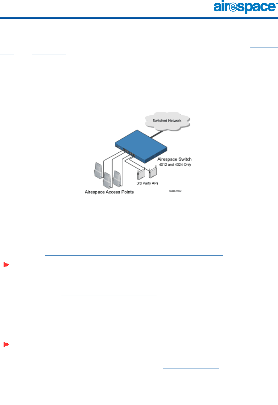
10/10/03 Direct Connect Mode
90-100584-004 Airespace Product Guide 31
Airespace Wireless Switch Direct Connect ModeDir ect Conn ect Mod e
The 4012 and 4024 Airespace Wireless Switches can be operated in Direct Connect Mode, in Appliance
Mode, or in Hybrid Mode. In Direct Connect Mode, the Airespace Wireless Switches are directly
connected to up to 24 (Model 4024) or up to 12 (Model 4012) Airespace APs and/or third-party APs
over CAT-5 or higher Ethernet cabling. The benefit of this mode is that the Airespace Wireless Switches
can provide Power Over Ethernet.
The following figure shows an Airespace Wireless Switch in the Direct Connect Mode, and the rest of the
section describes the 4012 and 4024 Airespace Wireless Switch connections to the switched network.
Figure - Airespace Wireless Switch Direct Connect Mode
The Airespace Wireless Switch filters packets and forwards them between LAN segments. When the
Airespace Wireless Switch is operated in Direct Connect Mode, it transmits data between all connected
Airespace APs and third-party APs, which results in fewer packets being placed on the backbone
network.
The 4012 and 4024 Airespace Wireless Switches communicate with the backbone network via a
1000Base-T or 1000Base-SX Network Port, or via front-panel 10/100Base-T Ethernet Port 1 as
described in the Switched Network Connection to an Airespace Switch or Appliance section.
Note: When you use front-panel 10/100Base-T Ethernet Port 1 to communicate with the
switched network, you can no longer use that port to communicate with an Airespace AP or
third-party AP.
The Airespace Wireless Switch or WLAN Appliance uses industry-standard SNMP traps and flags to
communicate with the Airespace Control System Software, and communicates with AireOS manage-
ment interfaces as follows:
•With an optional ACS Software Server or other AireOS management interface, either directly
connected or through an out-of-band AireOS Management Network, or via a dedicated 10/
100Base-T Service (Management) Port.
•With an optional VT-100 CLI console via a serial RS232-C Console Port.
Note: Airespace recommends that you not use the switched network for your AireOS manage-
ment, because a service outage on your switched network means that you have no dedicated
path to the Airespace Wireless Switch.
The Airespace Wireless Switch can be equipped with built-in Power Over Ethernet circuitry or an
external PoE hub, which allows associated Airespace APs and/or third-party APs to receive power over
the CAT-5 Ethernet cabling.
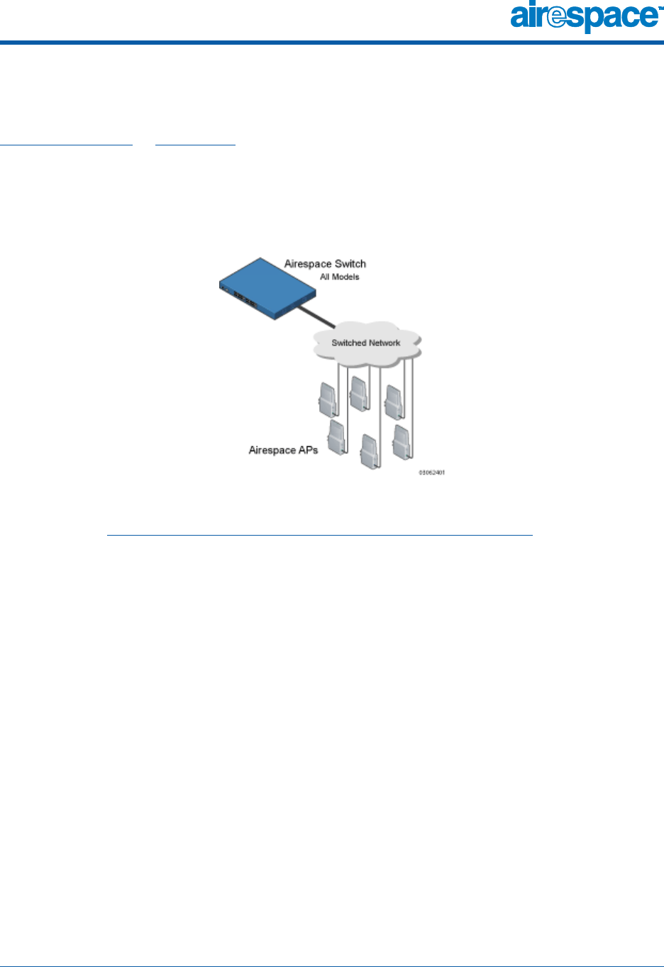
10/10/03 Appliance Mode
90-100584-004 Airespace Product Guide 32
Airespace Switches and Appliances in Appliance ModeAppliance Mode
All 4012 and 4024 Airespace Wireless Switches and 4101 and 4102 Airespace WLAN Appliances can be
operated in Appliance Mode. (The 4012 and 4024 Airespace Wireless Switches can also be operated in
Direct Connect Mode or Hybrid Mode.) In Appliance Mode, the Airespace Switch or Appliance communi-
cates indirectly with up to 36 (Models 4101 and 4102), up to 24 (Model 4024) or up to 12 (Model 4012)
associated Airespace APs (and/or third-party APs for 4012 or 4024 Airespace Wireless Switches)
through the switched network. The following figure shows an Airespace Switch or Appliance in
Appliance Mode.
Figure - Airespace Wireless Switch or WLAN Appliance Deployed in Appliance Mode
The Airespace Switch or Appliance communicates with the switched network using one of the interfaces
described in the Switched Network Connection to an Airespace Switch or Appliance section.
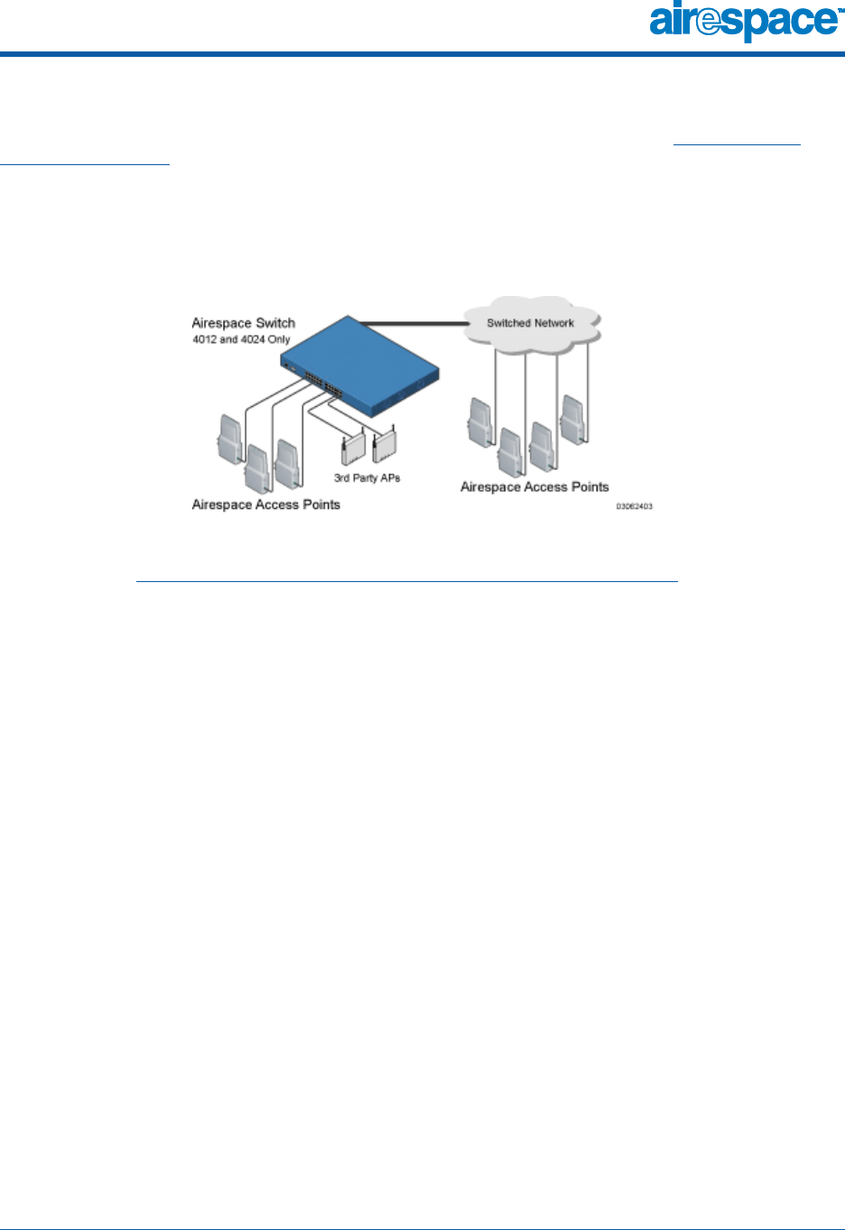
10/10/03 Hybrid Mode
90-100584-004 Airespace Product Guide 33
Airespace Wireless Switch Hybrid ModeHybrid Mode
The 4012 and 4024 Airespace Wireless Switches can be operated in Hybrid Mode, Appliance Mode or
Direct Connect Mode. In Hybrid Mode, the Airespace Wireless Switch communicates directly and indi-
rectly with up to 24 (Model 4024) or up to 12 (Model 4012) associated Airespace APs and/or third-party
APs over Ethernet cabling, and with associated Airespace APs through the switched network. The
following figure shows an Airespace Wireless Switch in Hybrid Mode.
Figure - Airespace Wireless Switch Deployed in Hybrid Mode
The Airespace Wireless Switch communicates with the switched network using one of the interfaces
described in the Switched Network Connection to an Airespace Switch or Appliance section.

10/10/03 Distribution System Port
90-100584-004 Airespace Product Guide 34
About the Distribution System PortD istribution System Port
As described in Switched Network Connection to an Airespace Switch or Appliance, the 4012 and 4024
Airespace Wireless Switch and 4101 Airespace WLAN Appliance logical Distribution System port can be
assigned to only one physical port (Airespace Wired Connections), and can communicate with the
switched network through one physical port. The 4102 Airespace WLAN Appliance uses two redundant
physical ports to ensure continued communications through the switched network in case part of the
switched network fails.
Note: The Distribution System Port cannot be assigned to the dedicated Airespace Switch or
Appliance front-panel Service (Management) Port.
The Distribution System port provides an uplink to the switched network. As such, it:
•Sends messages through the switched network to autodiscover and communicate with other
Airespace Switches and Appliances.
•Listens across the switched network for Airespace AP polling messages to autodiscover,
associate with, and communicate with as many Airespace APs as it is configured to allow.
Note: Should another Airespace WLAN Appliance or Airespace Wireless Switch in Appliance
Mode fail, its dropped Airespace APs poll the switched network for another Airespace Switch or
Appliance. When an online Airespace Switch or Appliance has any remaining primary or
emergency Ethernet ports, it listens to the switched network for Airespace AP polling
messages to autodiscover, associate with, and communicate with as many Airespace APs as it
is configured to allow. Refer to the Airespace Switch and Appliance Failover Protection section
for more information.
The Distribution System port is the logical port through which the Airespace Switch or Appliance talks to
the switched network, and must be configured for the following:
•Airespace Switch or Appliance statically set IP address, IP netmask, and default router.
•Physical port assignment.
•If required, VLAN assignment.
•Web and Secure Web modes.
•Spanning Tree Protocol, if required.
Refer to the Configuring the Airespace Switch or Appliance section for configuration instructions.

10/10/03 Service (Management) Port
90-100584-004 Airespace Product Guide 35
About the Service (Management) PortService (Management) Port
The Service Port on the Airespace Wireless Switch or WLAN Appliance front panel is a 10/100Base-T
Ethernet port dedicated to AireOS management. The Service Port is configured with an IP address,
subnet mask, and IP assignment protocol separate from the Distribution System Port. This allows the
operator to manage the Airespace Switch or Appliance directly or through a dedicated AireOS manage-
ment network, such as 10.1.2.x, which can ensure AireOS management access during switched
network downtime.
Airespace created the Service (Management) port to remove the Airespace System management from
the switched network data stream to improve security and to provide a faster management connection.
Note that you cannot assign a Gateway to the Service (Management) Port, and so the Port is not
routable, unlike the other front-panel 10/100Base-T ports.
Also note that the Service Port is not auto-sensing, unlike the other front-panel 10/100Base-T ports:
you must use the correct straight-through or crossover Ethernet cable to communicate with the Service
(Management) Port.
Refer to the Configuring Other Ports and Parameters for information on how to configure the Service
Port.

10/10/03 Startup Wizard
90-100584-004 Airespace Product Guide 36
About the Startup WizardStartup Wizard
When an Airespace Wireless Switch or WLAN Appliance is powered up with a new factory AireOS
software load or after being reset to factory defaults, the bootup script runs the Startup Wizard, which
prompts the installer for initial configuration. The Startup Wizard:
•Ensures that the Airespace Switch or Appliance has a System Name, up to 32 characters.
•Adds an Administrative User Name and Password, each up to 24 characters.
•Ensures that the Airespace Switch or Appliance can communicate with the CLI, ACS Software,
or Web Browser AireOS management interfaces (either directly or indirectly) through the
Service (Management) Port by accepting a valid IP configuration protocol (none or DHCP), and
if ‘none’, IP address and netmask. If you do not want to use the Service (Management) Port,
enter 0.0.0.0 for the IP address and netmask; this disables the Service Port.
Note: Airespace recommends that you not use the switched network for your AireOS manage-
ment, because a service outage on your switched network means that you have no dedicated
path to the Airespace Wireless Switch.
•Ensures that the Airespace Switch or Appliance can communicate with the switched network
(802.11 Distribution System) through the Distribution System Port by collecting a valid static IP
configuration protocol (none), IP address, netmask, default router, and physical port
assignment.
•Collects the WLAN 1 802.11 SSID, or Network Name.
•Enables and/or disables the 802.11b/g and 802.11a Airespace AP networks.
•Enables or disables AireWave Director Software.
To use the Startup Wizard, refer to Using the Startup Wizard.

10/10/03 Airespace Switch and Appliance Memory
90-100584-004 Airespace Product Guide 37
About Airespace Switch and Appliance MemoryAirespace Switch and Appliance Memory
The Airespace Wireless Switches and WLAN Appliances contain two kinds of memory: volatile RAM,
which holds the current, active Airespace Switch or Appliance configuration, and NVRAM (non-volatile
RAM), which holds the reboot configuration. When you are configuring the AireOS in an Airespace
Switch or Appliance, you are modifying volatile RAM; you must save the configuration from the volatile
RAM to the NVRAM to ensure that the Airespace Switch or Appliance reboots in the current
configuration.
Knowing which memory you are modifying is important when you are:
•Using the Startup Wizard
•Clearing Configurations
•Saving Configurations
•Resetting the Airespace Switch or Appliance
•Logging Out of the CLI

10/10/03 Airespace Switch and Appliance Failover Protection
90-100584-004 Airespace Product Guide 38
Airespace Switch and Appliance Failover ProtectionAirespace Switch and Appliance Failover Protection
Each Airespace Wireless Switch and WLAN Appliance with front-panel 10/100Base-T ports can normally
associate with as many primary Airespace APs as it has physical ports. Thus, a 12-port 4012 Airespace
Wireless Switch can associate with 12 primary Airespace APs, and a 24-port 4024 Airespace Wireless
Switch can associate with 24 primary Airespace APs.
However, each 4012 and 4024 Airespace Wireless Switch can also associate with as many secondary
Airespace APs as it has physical ports. Thus, a 12-port 4012 Airespace Wireless Switch can associate
with 24 Airespace APs (12 primary and 12 secondary), and a 24-port 4024 Airespace Wireless Switch
can associate with 48 Airespace APs (24 primary and 24 secondary).
Model 4101 and 4102 Airespace WLAN Appliances can associate with up to 36 Airespace APs, and have
no front-panel 10/100Base-T ports. Note that the 4101 and 4102 Airespace WLAN Appliances associate
with 36 primary Airespace APs and no secondary Airespace APs.
In a multiple-Airespace Switch and Appliance system (refer to Multiple-Airespace Switch and Appliance
Deployments), this means that if one Airespace Switch or Appliance fails, its dropped Airespace APs
immediately do the following under direction of the AireWave Director Software:
•If the Airespace AP has a Primary Airespace Switch or Appliance assigned, it attempts to
associate with that Airespace Switch or Appliance.
•If the Airespace AP has no Primary Airespace Switch or Appliance assigned or if its Primary
Airespace Switch or Appliance is unavailable, it attempts to associate with a Master Airespace
Switch or Appliance on the same subnet.
•If the Airespace AP has no Primary Airespace Switch or Appliance assigned and there is no
Master Airespace Switch or Appliance active, it attempts to associate with the least-loaded
Airespace Switch or Appliance on the same subnet to respond with unused primary or
secondary ports.
This means that when sufficient Airespace Switches and Appliances are deployed in Appliance Mode,
should one Airespace Switch or Appliance fail, active Airespace AP client sessions are momentarily
dropped while the dropped Airespace AP associates with an unused port on another Airespace Switch or
Appliance, allowing the client device to immediately reassociate and reauthenticate.
Because the Airespace APs and/or third-party APs plug into the front of the Airespace Wireless Switch
when it is deployed in Direct Connect Mode, Airespace Switch and Appliance failover protection is not
supported for Airespace APs in Direct Connect Mode.
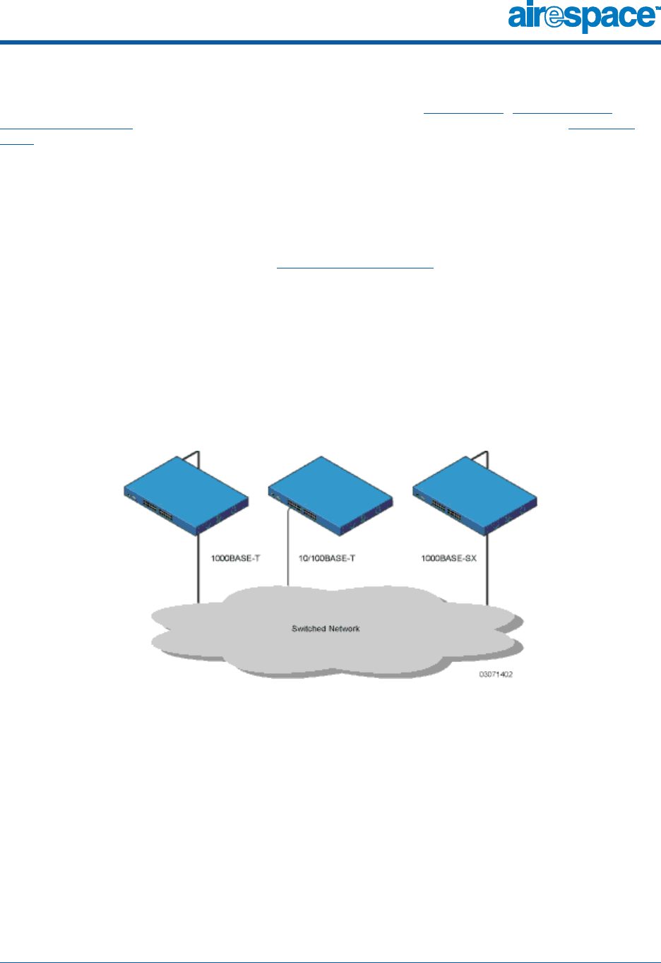
10/10/03 Switched Network Connection to an Airespace Switch or Appliance
90-100584-004 Airespace Product Guide 39
Switched Network Connection to the Airespace Switch or ApplianceSwitched Network Conn ection to an Airespace Switch or Appliance
The 4012 and 4024 Airespace Wireless Switch can be operated in Hybrid Mode, Appliance Mode or
Direct Connect Mode. The 4101 and 4102 Airespace WLAN Appliance can be operated in Appliance
Mode. Regardless of operating mode, the Airespace Switches and Appliances use the switched network
as an 802.11 Distribution System.
Regardless of the Ethernet port type or speed, each Airespace Switch and Appliance monitors and
communicates with its related Airespace Switches and Appliances across the switched network.
Model 4012 and 4024 Airespace Wireless SwitchesModel 4012 and 4024 Airespace Wireless Switches
The 4012 and 4024 Airespace Wireless Switch can communicate with the switched network through one
of three physical interfaces, but the logical Distribution System Port can be assigned to only one
physical port. The three physical interfaces are:
•A GigE 1000Base-SX fiber-optic cable can plug into the optional LC connector (AS-Switch-GSX)
Network Adapter Module on the rear of the Airespace Wireless Switch.
•Alternatively, a GigE 1000Base-T copper cable can plug into the optional RJ-45 (AS-Switch-GT)
Network Adapter Module connector on the rear of the Airespace Wireless Switch.
•Alternatively, one Ethernet 10/100Base-T cable can plug into Port 1 of the RJ-45 10/100Base-T
connectors on the front of the Airespace Wireless Switch.
Figure - Physical Switched Network Connections to the 4012 and 4024 Airespace Wireless Switch
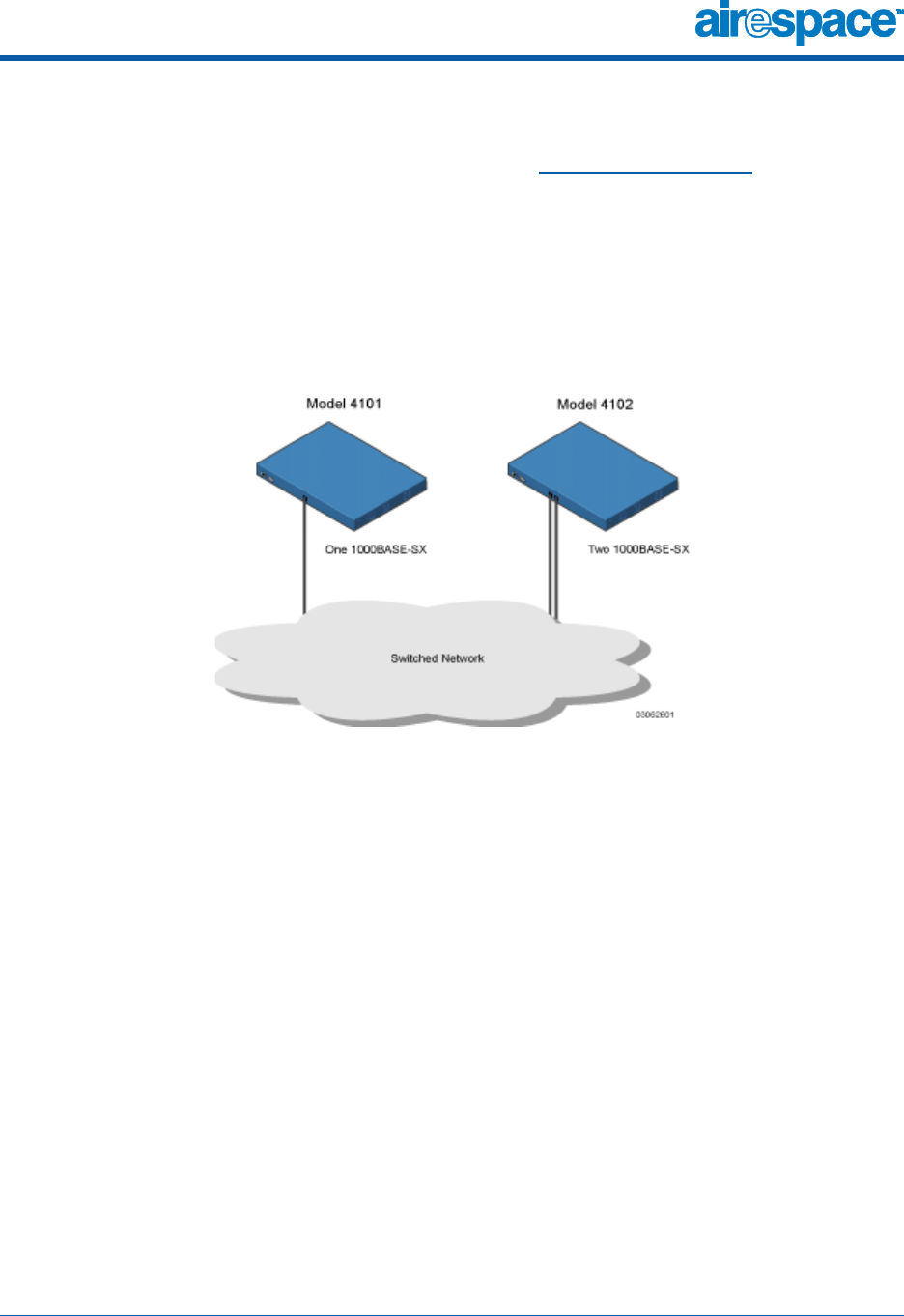
10/10/03 Switched Network Connection to an Airespace Switch or Appliance
90-100584-004 Airespace Product Guide 40
Model 4101 and 4102 Airespace WLAN AppliancesModel 4101 and 4102 Airespace WLAN Appliances
The 4101 and 4102 Airespace WLAN Appliances can communicate with the switched network through
one (4101) or two (4102) physical interfaces, and the logical Distribution System Port can be assigned
to the one or two physical ports. The physical interfaces areas follows:
•A GigE 1000Base-SX fiber-optic cable can plug into the LC connector on the front of the 4101
Airespace WLAN Appliance.
•Two GigE 1000Base-SX fiber-optic cables can plug into the LC connectors on the front of the
4102 Airespace WLAN Appliance. Note that the two GigE ports are redundant--the first port that
becomes active is the master, and the second port becomes the backup port.
Figure - Physical Switched Network Connections to the 4101 and 4102 Airespace WLAN Appliance
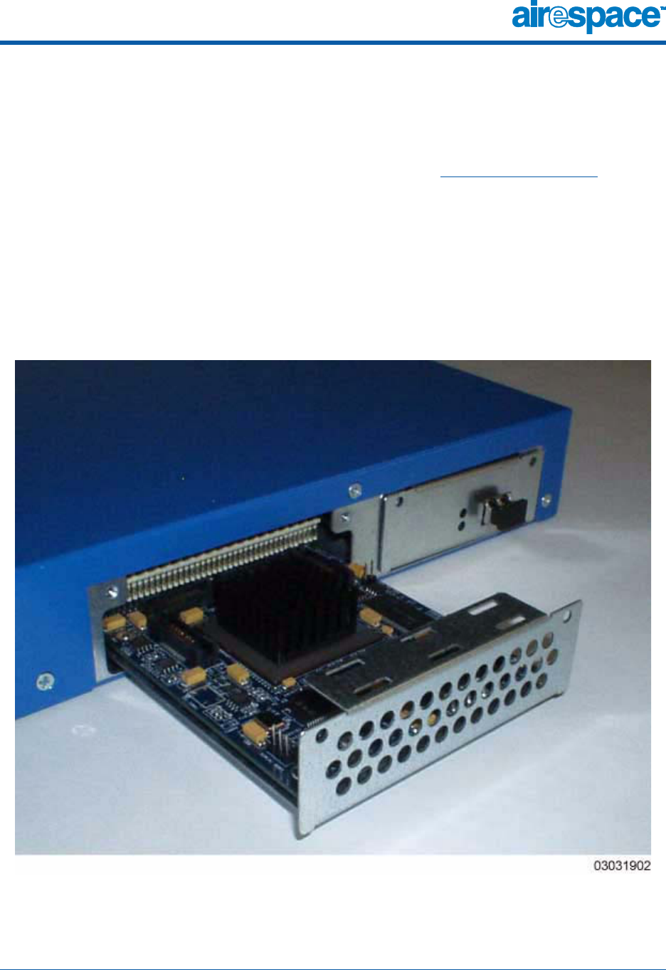
10/10/03 Enhanced Security Module
90-100584-004 Airespace Product Guide 41
Enhanced Security ModuleEnhanced Security M odule
The 4012 and 4024 Airespace Wireless Switches can be equipped with an optional Enhanced Security
Module (AS-Switch-ESM), which slides into the rear panel of the Airespace Wireless Switches, and
which is factory-installed inside the chassis in the 4101 and 4102 Airespace WLAN Appliances. The
Enhanced Security Module adds significant hardware encryption acceleration to the Airespace Wireless
Switch or WLAN Appliance, which enables the following through the Distribution System Port:
•Sustain up to 1 Gbps throughput with Layer 2 and Layer 3 encryption enabled.
•Provide a built-in VPN server for mission-critical traffic.
•Support high-speed, processor-intensive encryption, such as IPSec and 3DES.
•Provides sufficient processor power to have six or more WLANs active at any given time.
The following figure shows the Enhanced Security Module sliding into the rear of a 4012 or 4024
Airespace Wireless Switch.
Figure - 4012 and 4024 Airespace Wireless Switch Enhanced Security Module Location
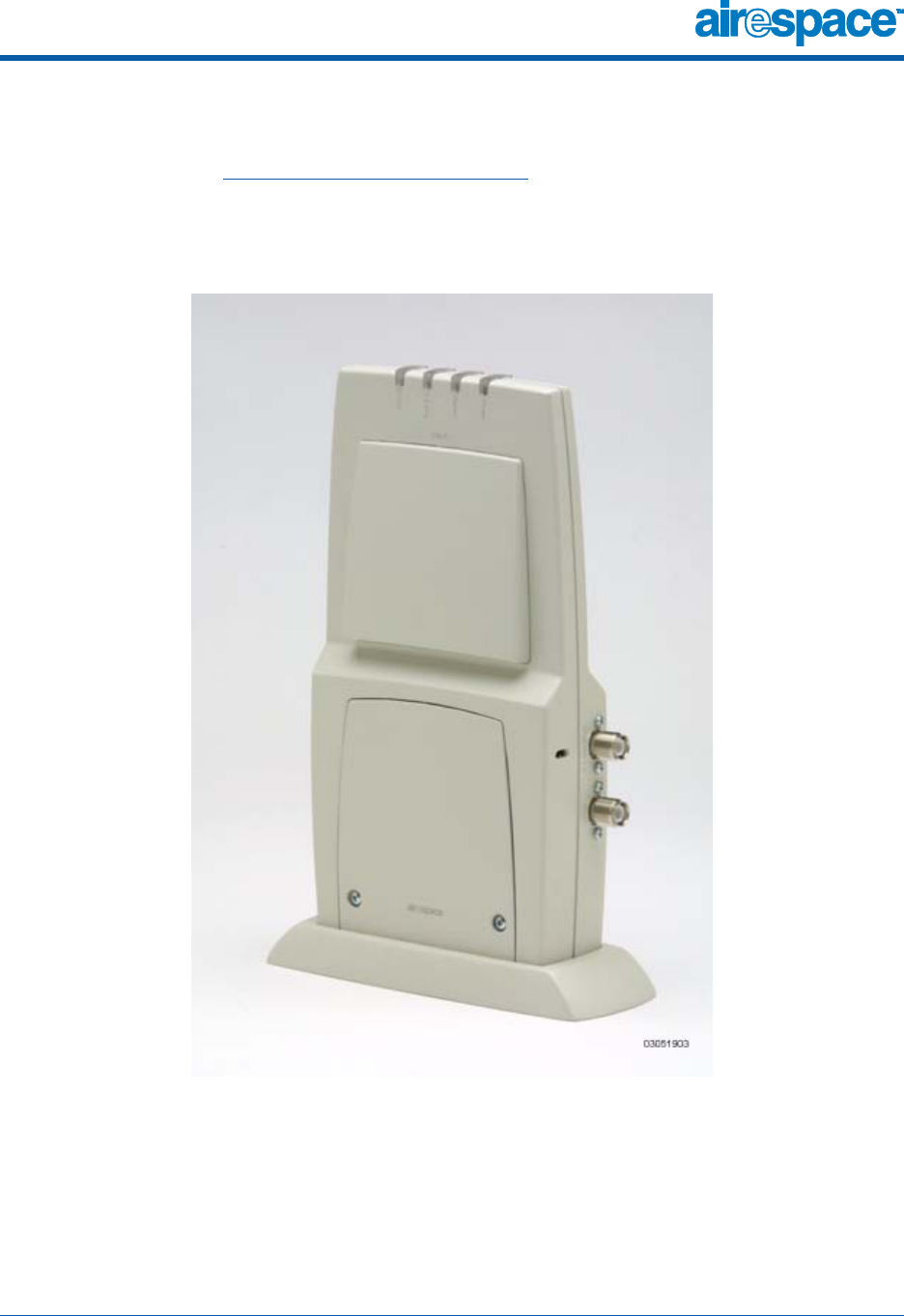
10/10/03 Airespace Access Points
90-100584-004 Airespace Product Guide 42
About Airespace Access PointsAiresp ace Access Point s
The Airespace AP is a part of the innovative Airespace Wireless Enterprise Platform (Airespace System).
When associated with an Airespace Switches and Appliances as described below, the Airespace AP
provides advanced 802.11a and/or 802.11b/g Access Point functions in a single aesthetically pleasing
enclosure. The following figure shows the Airespace Access Point.
Figure - Airespace Access Point with Ceiling-Mount Base
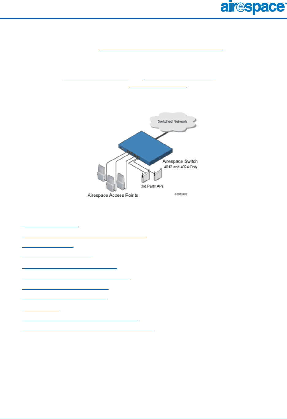
10/10/03 Airespace Access Points
90-100584-004 Airespace Product Guide 43
Note that the Airespace AP is manufactured in a neutral color so it blends into most environments (but
can be painted), contains pairs of high-gain internal antennas for unidirectional (180-degree) or omni-
directional (360-degree) coverage (Airespace AP External and Internal Antennas), and is plenum-rated
for installations in hanging ceiling spaces.
In the Airespace System, most of the processing responsibility is removed from traditional SOHO (small
office, home office) APs and resides in the Airespace Wireless Switches and WLAN Appliances. The
following figure shows Airespace Access Points and Third-Party Access Points connected to the 4012 or
4024 Airespace Wireless Switch front panel in Direct Connect Mode.
Figure - 4012 and 4024 Airespace Wireless Switch and Access Points
Refer to the following for more information on Airespace APs:
•Airespace AP Models
•Airespace AP External and Internal Antennas
•Airespace AP LEDs
•Airespace AP Connectors
•Airespace AP Power Requirements
•Airespace AP External Power Converter
•Airespace AP Mounting Options
•Airespace AP Physical Security
•Monitor Mode
•Airespace Access Point Deployment Guide
•Airespace Access Point Quick Installation Guide
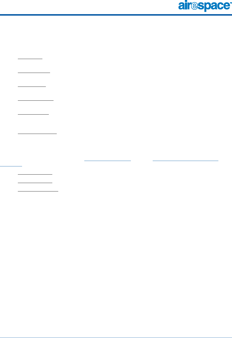
10/10/03 Airespace AP Models
90-100584-004 Airespace Product Guide 44
About Airespace AP ModelsAir espa ce AP Mo dels
The Airespace AP includes one 802.11a radio (AS-1200-A), one 802.11b/802.11g radio (AS-1200-BG),
or one 802.11a and one 802.11b/g radio (AS-1200-ABG). The Airespace AP is available in the following
configurations:
•AS-1200-A - Airespace AP with one 802.11a radio, two high-gain internal antennas, and one
5 GHz external antenna adapter
•AS-1200-A-int - Airespace AP with one 802.11a radio, two high-gain internal antennas, and no
external antenna adapters
•AS-1200-BG - Airespace AP with one 802.11b/g radio and four high-gain internal antennas, one
5 GHz external antenna adapter, and two 2.4 GHz external antenna adapters
•AS-1200-BG-int - Airespace AP with one 802.11b/g radio, four high-gain internal antennas, and
no external antenna adapters
•AS-1200-ABG - Airespace AP with one 802.11a and one 802.11b/g radio and four high-gain
internal antennas, one 5 GHz external antenna adapter, and two 2.4 GHz external antenna
adapters
•AS-1200-ABG-int - Airespace AP with one 802.11a and one 802.11b/g radio, four high-gain
internal antennas, and no external antenna adapters
The Airespace AP is shipped with a color-coordinated ceiling mount base, and projection and flush wall
mount brackets. These brackets and base allow quick mounting to ceiling or wall.
The Airespace AP can be powered by Power Over Ethernet or by an Airespace AP External Power
Converter. The two power converter models are:
•AS-AP-PWR110 - External 110 VAC-to-48 VDC Power Converter for any Airespace AP
•AS-AP-PWR220 - External 220 VAC-to-48 VDC Power Converter for any Airespace AP
•AS-AP-PWR_UNIV - External 110-220 VAC-to-48 VDC Power Converter for any Airespace AP
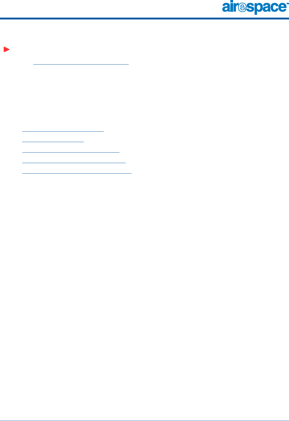
10/10/03 Airespace AP External and Internal Antennas
90-100584-004 Airespace Product Guide 45
About Airespace AP External and Internal AntennasAirespace AP External and Internal Antennas
Note: Airespace APs must use the factory-supplied internal or external antennas to avoid
violating FCC requirements and voiding the user’s authority to operate the equipment. Refer
to FCC Statements for Airespace APs for detailed information.
The 1200 Airespace AP enclosure contains one 802.11a and/or one 802.11b/g radio and four (two
802.11a and two 802.11b/g) high-gain antennas, which can be independently enabled or disabled to
produce a 360-degree omnidirectional coverage area.
Also note that the wireless LAN operator can disable either one of each pair of the Airespace AP internal
antennas to produce a 180-degree sectorized coverage area. This feature can be useful, for instance,
for outside-wall mounting locations where coverage is only desired inside the building.
The following sections contain more information about Airespace AP internal and external antennas:
•External Antenna Connectors
•Antenna Sectorization
•802.11a Internal Antenna Patterns
•802.11b/g Internal Antenna Patterns
•802.11a/b/g Internal Antenna Patterns
External Antenna ConnectorsExternal Antenna Connectors
The AS-1200-A, AS-1200-BG, and AS-1200-ABG Airespace APs have male reverse-polarity TNC jacks
for installations requiring factory-supplied external directional or high-gain antennas. The external
antenna option can create more flexibility in Airespace AP and antenna placement.
Note that the 802.11b/g 2.4 GHz Left external antenna connector is associated with the internal Side A
antenna, and that the 2.4 GHz Right external antenna connector is associated with the internal Side B
antenna. When you have 802.11b/g diversity enabled, the Left external or Side A internal antennas are
diverse from the Right external or Side B internal antennas.
Also note that the 802.11a 5 GHz Left external antenna connector is separate from the internal
antennas, and adds diversity to the 802.11a transmit and receive path.
Finally, note that the AS-1200-A-int, AS-1200-BG-int, and AS-1200-ABG-int Airespace APs are not
equipped with external antenna jacks, and are used for installations requiring only internal Airespace
AP antennas.
Antenna SectorizationAntenna Sectoriz ation
Note that the Airespace System supports Antenna Sectorization, which can be used to increase the
number of clients and/or client throughput in a given air space. Installers can mount two Airespace APs
back-to-back and the Airespace System operator can disable the second antenna in both Airespace APs
to create a 360-degree coverage area with two sectors.
802.11a Internal Antenna Patterns802.11a Internal Antenna Patterns
The 1200 Airespace AP can contain one 802.11a radio which drives two fully-enclosed high-gain
antennas which can provide a large 360-degree coverage area. The two internal antennas can be used
at the same time to provide a 360-degree (Omnidirectional) coverage area, or either antenna can be
disabled to provide a 180-degree (Sectorized) coverage area.
When equipped with an optional factory-supplied external antenna, the 802.11a radio supports receive
and transmit diversity between the internal antenna and the external antenna. The diversity function
provided by Airespace radios can result in lower multipath fading, fewer packet retransmissions, and
higher client throughput.
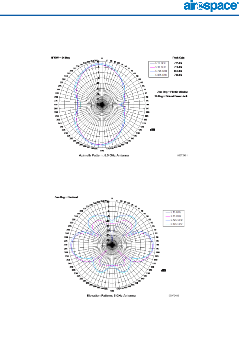
10/10/03 Airespace AP External and Internal Antennas
90-100584-004 Airespace Product Guide 46
Figure - 1200 Airespace AP 802.11a OMNI (Dual Internal) Azimuth Antenna Gain Pattern
Figure - 1200 Airespace AP 802.11a OMNI (Dual Internal) Elevation Antenna Gain Pattern
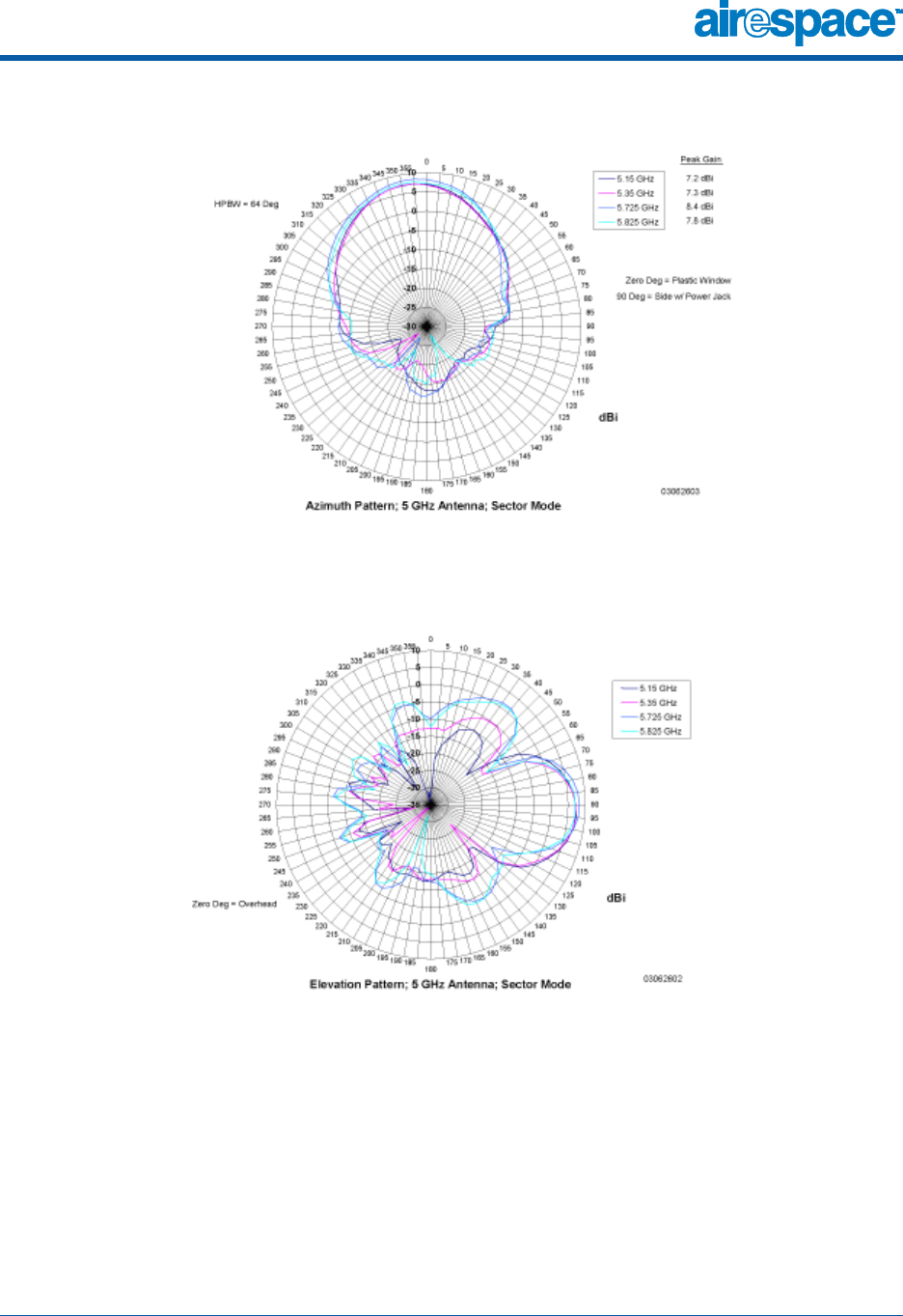
10/10/03 Airespace AP External and Internal Antennas
90-100584-004 Airespace Product Guide 47
Figure - 1200 Airespace AP 802.11a Sectorized (Single Internal) Azimuth Antenna Gain Pattern
Figure - 1200 Airespace AP 802.11a Sectorized (Single Internal) Elevation Antenna Gain Pattern
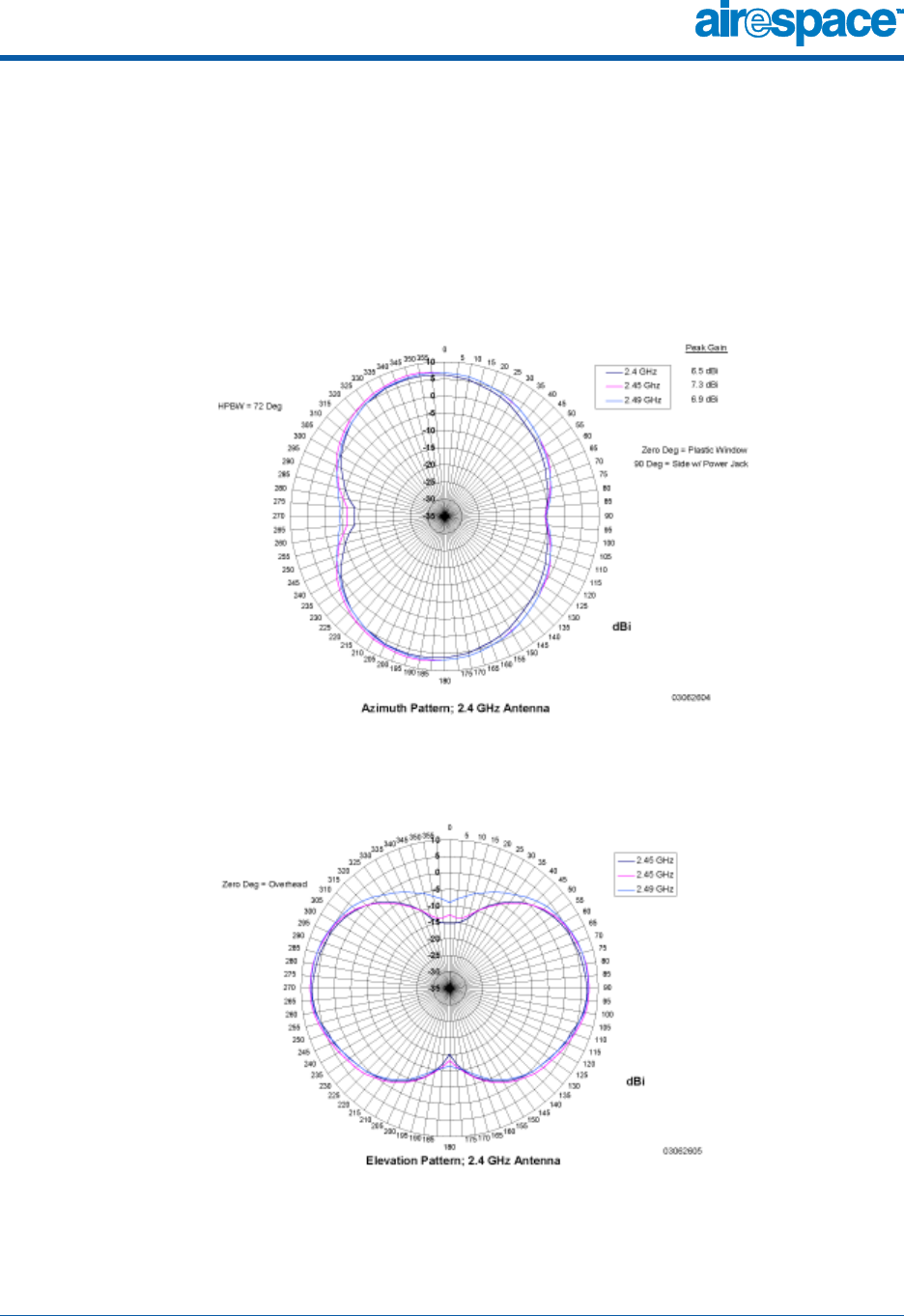
10/10/03 Airespace AP External and Internal Antennas
90-100584-004 Airespace Product Guide 48
802.11b/g Internal Antenna Patterns802.11b/g Internal Antenna Patterns
The 1200 Airespace AP enclosure can contain one 802.11b/g radio which drives two fully-enclosed
high-gain antennas which can provide a large 360-degree coverage area. The two internal antennas
can be used at the same time to provide a 360-degree (Omnidirectional) coverage area, or either
antenna can be disabled to provide a 180-degree (Sectorized) coverage area.
The 802.11b/g radio supports receive and transmit diversity between the internal antennas and/or
optional factory-supplied external antennas.
Figure - 1200 Airespace AP 802.11b/g OMNI (Dual Internal) Azimuth Antenna Gain Pattern
Figure - 1200 Airespace AP 802.11b/g OMNI (Dual Internal) Elevation Antenna Gain Pattern
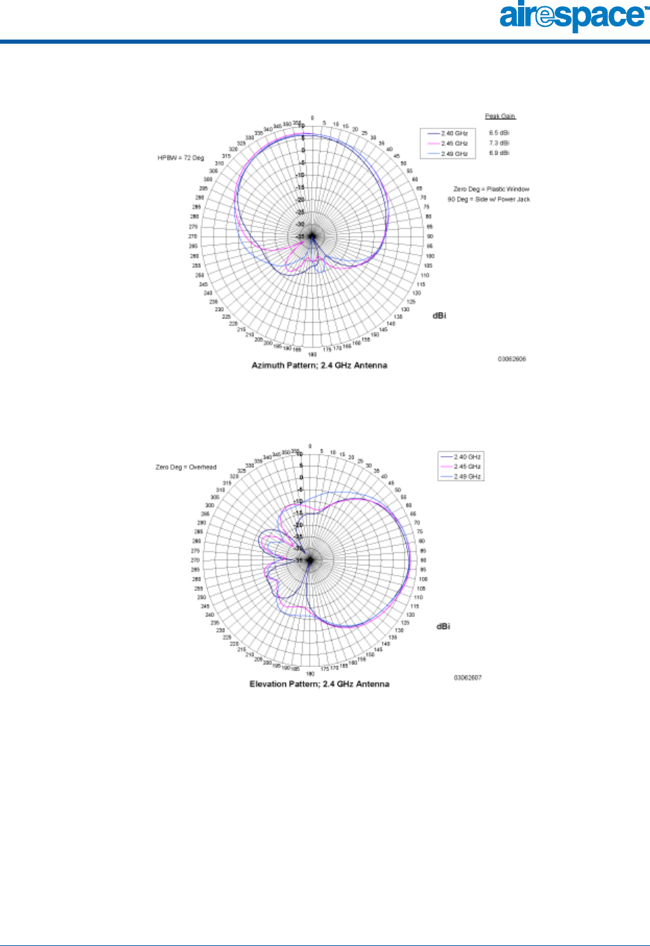
10/10/03 Airespace AP External and Internal Antennas
90-100584-004 Airespace Product Guide 49
Figure - 1200 Airespace AP 802.11b/g Sectorized (Single Internal) Azimuth Antenna Gain Pattern
Figure - 1200 Airespace AP 802.11b/g Sectorized (Single Internal) Elevation Antenna Gain Pattern

10/10/03 Airespace AP External and Internal Antennas
90-100584-004 Airespace Product Guide 50
802.11a/b/g Internal Antenna Patterns802.11a/b/g Internal Antenna Patte rns
The AS-1200-ABG Airespace AP enclosure contains one 802.11a and one 802.11b/g radio and four
fully-enclosed high-gain antennas which provide large 360-degree 802.11a and 802.11b/g coverage
areas, a shown in the 802.11a Internal Antenna Patterns and 802.11b/g Internal Antenna Patterns
sections.
Note that the 802.11b/g radio supports receive and transmit diversity between the internal antennas,
while the 802.11a radio only supports diversity between the internal antennas and an optional
factory-supplied external antenna.

10/10/03 Airespace AP LEDs
90-100584-004 Airespace Product Guide 51
About Airespace AP LEDsAi respa ce AP LED s
Each Airespace AP is equipped with four LEDs across the top of the case. They can be viewed from
nearly any angle. The LEDs indicate power and fault status, 2.4 GHz (802.11b/g) radio activity, and
5 GHz (802.11a) radio activity.
This LED display allows the wireless LAN manager to quickly monitor the Airespace AP status. For more
detailed troubleshooting instructions, refer to the Troubleshooting section.

10/10/03 Airespace AP Connectors
90-100584-004 Airespace Product Guide 52
About Airespace AP ConnectorsAirespace AP Connectors
The Airespace AP has the following external connectors:
•One RJ-45 Ethernet jack, used for connecting the Airespace AP to the 4012 or 4024 Airespace
Wireless Switch or to the switched network.
•One 48 VDC power input jack, used to plug in an optional factory-supplied external power
adapter.
•Three male reverse-polarity TNC antenna jacks, used to plug optional external antennas into
the Airespace AP: two for an 802.11b/g radio, and one for an 802.11a radio.
Figure - Airespace AP External Connectors
The Airespace AP communicates with an Airespace Wireless Switch or WLAN Appliance using standard
CAT-5 (Category 5) or higher 10/100 Mbps twisted pair cable with RJ-45 connectors. Plug the CAT-5
cable into the RJ-45 jack on the side of the Airespace AP.
Note that the Airespace AP can receive power over the CAT-5 cable from the Airespace Wireless Switch
or switched network equipment. Refer to Power Over Ethernet for more information about this option.

10/10/03 Airespace AP Connectors
90-100584-004 Airespace Product Guide 53
The Airespace AP can be powered from an optional factory-supplied external AC-to-48 VDC power
adapter. If you are powering the Airespace AP using an external adapter, plug the adapter into the
48 VDC power jack on the side of the Airespace AP.
The Airespace AP includes two 802.11a and two 802.11b/g high-gain internal antennas, which provide
omnidirectional coverage. However, some Airespace AP models can also use optional factory-supplied
external high-gain and/or directional antennas, as described in Airespace AP External and Internal
Antennas. When you are using external antennas, plug them into the male reverse-polarity TNC jacks
on the side of the Airespace AP as described in the Airespace Access Point Quick Installation Guide.
Note: The Airespace APs must use the factory-supplied internal or external antennas to avoid
violating FCC regulations and voiding the user’s authority to operate the equipment, as
described in FCC Statements for Airespace APs.
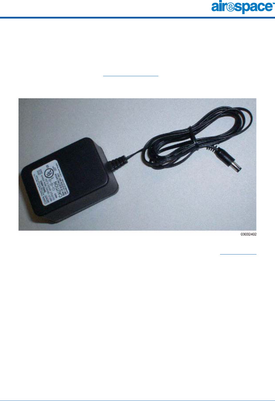
10/10/03 Airespace AP Power Requirements
90-100584-004 Airespace Product Guide 54
About Airespace AP Power RequirementsAirespace AP Power Requirements
The Airespace AP requires a 48 VDC nominal (between 38 and 57 VDC) power source capable of
providing 7 Watts. The polarity of the DC source does not matter because the Airespace AP can use
either a +48 VDC or a -48 VDC nominal source.
Airespace APs can receive power from an external power converter (see figure below) plugged into the
side of the Airespace AP case, or from Power Over Ethernet.
Figure - Typical Airespace AP External Power Converter
For more information about the Airespace AP specifications and capacities, refer to Specifications, to be
determined.

10/10/03 Airespace AP External Power Converter
90-100584-004 Airespace Product Guide 55
About Airespace AP External Power ConverterAirespac e AP External Power Converter
The Airespace AP can receive power from an external 115 VAC-to-48 VDC power converter or from
Power Over Ethernet equipment.
The external power converter plugs into a secure 115 VAC convenience outlet (to avoid having cleaning
personnel unplug the converter when they use power cleaning equipment). The converter produces the
required 48 VDC output (Airespace AP Power Requirements) for the Airespace AP. The converter output
feeds into the side of the Airespace AP through a 48 VDC jack (Airespace AP Connectors).

10/10/03 Airespace AP Mounting Options
90-100584-004 Airespace Product Guide 56
About Airespace AP Mounting OptionsAirespace AP Mounting Options
Refer to the Airespace Access Point Quick Installation Guide for the Airespace AP mounting options.

10/10/03 Airespace AP Physical Security
90-100584-004 Airespace Product Guide 57
About Airespace AP Physical SecurityAirespace AP Physical Security
The side of the Airespace AP housing includes a slot for a Kensington MicroSaver Security Cable. You
can use any MicroSaver Security Cable to ensure that your Airespace AP stays where you mounted it!
Refer to the Kensington website for more information about their security products, or to the Airespace
Access Point Quick Installation Guide for installation instructions.

10/10/03 Monitor Mode
90-100584-004 Airespace Product Guide 58
About Airespace AP Monitor ModeMonitor Mode
The Airespace APs, Airespace Wireless Switches, and Airespace WLAN Appliances are capable of
performing rogue detection and containment while providing regular service. However, if the adminis-
trator would prefer to dedicate specific Airespace APs to rogue detection and containment, or if a
network that provides IDS only functions is desired, the Monitor mode should be enabled.
The Monitor function is set for all 802.11 radios on a per-Access Point basis in the Airespace APs >
Details section in the Using the Web Browser Interface.

10/10/03 Third-Party Access Points
90-100584-004 Airespace Product Guide 59
About Third-Party Access PointsTh ird-Party Access Points
The Airespace System can control all parameters for existing Cisco 1200, Cisco 350 and ORiNOCO 2000
Access Points using the third-party user interface from within the Airespace Control System Software
application. In addition, the Airespace System can be used to enforce real-time control of system-wide
802.1x security policies for third-party AP WLANs as described in AireOS Security.
Note: Third-party APs must be connected directly to the front panel of 4012 and 4024
Airespace Wireless Switches for the AireOS to control them using the third-party AP WLAN 17.
Because the 4101 and 4102 Airespace WLAN Appliances do not have front-panel AP ports,
WLAN 17 is not supported on the 4101 or 4102 Airespace WLAN Appliances.

10/10/03 Rogue Access Points
90-100584-004 Airespace Product Guide 60
About Rogue Access PointsRogue Access Point s
Because they are inexpensive an readily available, clients are plugging unauthorized rogue access
points (rogue APs) into existing LANs and building ad hoc wireless networks without IT department
knowledge or consent.
These rogues can be a serious breach of network security, because they can be plugged into a network
port behind the corporate firewall. Because clients generally do not enable any security settings on the
rogues, it is easy for unauthorized clients to use the access point to intercept network traffic and hijack
client sessions. Even more alarming, wireless clients and war chalkers frequently publish unsecure
access point locations, increasing the odds of having the enterprise security breached.
Rather than using a person with a scanner to manually detect rogue APs, the Airespace System auto-
matically collects information on rogue access points detected by its managed Airespace Access Points
and Third-Party Access Points, by MAC and IP address, and allows the system operator to tag and
monitor them as described in the Detecting and Monitoring Rogue Access Points section. Finally, the
AireOS can be used to discourage rogue AP clients by sending them deauthenticate and disassociate
messages from one to four Airespace APs. Because this real-time detection is automated, it saves labor
costs used for detecting and monitoring rogue APs while improving LAN security.
See also Rogue AP Tagging and Containment.

10/10/03 Rogue AP Tagging and Containment
90-100584-004 Airespace Product Guide 61
Rogue AP Tagging and ContainmentRogue AP Tagging and Containment
This built-in detection, tagging, monitoring and containment capability allows system administrators to
take required actions:
•Receive new rogue notifications, eliminating hallway scans.
•Monitor unknown rogues until they are eliminated or acknowledged.
•Determine the closest authorized Airespace Access Points and Third-Party Access Points,
making directed scans faster and more effective.
•Contain rogue APs by sending their clients deauthenticate and disassociate messages from one
to four Airespace APs.
•Tag rogue APs:
-Acknowledge rogue APs when they are outside of the LAN and do not compromise the
LAN or WLAN security.
-Accept rogue APs when they do not compromise the LAN or WLAN security.
-Tag rogue APs as unknown until they are eliminated or acknowledged.
-Tag rogue APs as contained and continue discouraging rogue AP clients from associat-
ing with the rogue AP, by having between one and four Airespace APs transmit deauth-
enticate and disassociate messages to the rogue AP clients. This function can contain
one or more channels on the same rogue AP.
To facilitate automated rogue detection in a crowded RF space, Airespace APs can be configured to
operate in Monitor Mode, allowing monitoring without creating unnecessary interference.

10/10/03 Airespace Control System Software
90-100584-004 Airespace Product Guide 62
About the Airespace Control System SoftwareAirespace Control System Software
The Airespace Control System Software (ACS Software Server) is an AireOS management tool that
extends the capabilities of the Airespace Web Browser Interface and the Airespace Command Line
Interface from an individual Airespace Wireless Switch or WLAN Appliance to a network of Airespace
Switches and Appliances.
The ACS Software Server includes the same configuration, performance monitoring, security, fault
management, and accounting options used at the Airespace Switch and Appliance level, but adds a
graphical view of multiple Airespace Wireless Switches, Airespace WLAN Appliances and managed
Access Points.
ACS Software Server simplifies adding and configuring Airespace Switches and Appliances while
decreasing data entry errors with the ACS Airespace Switch and Appliance Autodiscovery algorithm.
The ACS Software Server also uses industry-standard SNMP traps and flags to communicate with the
Airespace Switches and Appliances.
The ACS Software Server can be run as a normal Windows application, or can be installed as a service,
which runs continuously and resumes running after a reboot.
The value added by ACS Software Server includes graphical views of the following:
•ACS Airespace Switch and Appliance Autodiscovery of each Airespace Switch and Appliance as it
appears on the switched network.
•Auto-discovery of Airespace Access Points as they associate with operating Airespace Switches
and Appliances.
•Auto-discovery of Rogue Access Points and manual association of Third-Party Access Points
with Airespace Wireless Switches.
•Map-based organization of Access Point areas, helpful when the enterprise spans more than
one geographical area. (Refer to Configuring ACS Software.)
•User-supplied Campus, Building and Floor graphics, which show the following:
-Locations and status of managed Access Points. (Refer to Adding Devices to the ACS
Software Database.)
-Approximate locations of rogue APs, based on signal strength received by nearest man-
aged Airespace APs. (Refer to Detecting and Monitoring Rogue Access Points.)
-Locations of coverage holes, based on received signal strength from clients. (Refer to
Finding Coverage Holes.)
•System-wide control:
-Network, Airespace Wireless Switch, Airespace WLAN Appliance and managed AP con-
figuration is streamlined using customer-defined templates.
-Network, Airespace Wireless Switch, Airespace WLAN Appliance and managed AP status
and alarm monitoring.
-Automated monitoring: rogue APs, coverage holes, security violations, Airespace
Switches and Appliances, and Airespace APs.
-Full event logs available for rogue APs, coverage holes, security violations, Airespace
Switches and Appliances, and Airespace APs.
-Native third-party AP control and monitoring from within ACS Software Server.
-User-controllable AireWave Director Software.
-User-defined automatic Airespace Switches and Appliances status audits, missed trap
polling, configuration backups, and policy cleanups.

10/10/03 ACS Airespace Switch and Appliance Autodiscovery
90-100584-004 Airespace Product Guide 63
About ACS Airespace Switch and Appliance AutodiscoveryACS Airespace Switch and Appliance Autodiscover y
Manually adding Airespace Switch and Appliance data to a management database can be time
consuming, and is susceptible to data entry errors. The Airespace Control System Software (ACS
Software Server) includes a built-in Airespace Wireless Switch and WLAN Appliance Autodiscovery
function that speeds up database creation while eliminating errors.
Airespace Switch and Appliance Autodiscovery is limited to the Airespace Mobility Group defined by the
Airespace System operator.
The Using ACS Software Airespace Switch and Appliance Autodiscovery task allows operators to search
for a single Airespace Switch or Appliance by IP address, and facilitates a multiple-Airespace Switch or
Appliance search across a range of IP addresses. In either case, the Autodiscovery function finds all
Airespace Switches and Appliances on the switched network within the specified IP address range, and
automatically enters discovered Airespace Switch and Appliance information into the ACS Software
Server database.
Note: Airespace Switch and Appliance Autodiscovery can take a long time on a Class C address
range. Because of the large number of addresses in a Class B or Class A range, Airespace
recommends that you do not attempt Autodiscovery across Class B or Class A ranges.
As Airespace Access Points associate with an Airespace Switch or Appliance, the Airespace Switch or
Appliance immediately transmits the Airespace AP information to the Airespace Control System
Software, which automatically adds the Airespace AP to the ACS Software Server database.
Once the Airespace AP information is in the ACS Software Server database, operators can add the
Airespace AP to the appropriate spot on an ACS Software Server map using Arranging Airespace APs on
Floorplan Maps, so the topological map of the air space remains current.

10/10/03 Airespace Web Browser Interface
90-100584-004 Airespace Product Guide 64
About the Airespace Web Browser InterfaceAire space Web Browser I nterface
The Airespace Web Browser Interface is built into each Airespace Switch and Appliance. The Web
Browser Interface allows up to five users to simultaneously browse into the built-in Airespace Wireless
Switch or WLAN Appliance http/https (http + SSL) Web server, configure parameters, and monitor
operational status for the Airespace Switch or Appliance and its associated Access Points.
Note: Airespace strongly recommends that you enable the https: and disable the http: inter-
faces to ensure more robust security for your Airespace System.
Because the CLI works with one Airespace Switch or Appliance at a time, the Airespace Web Browser
Interface is especially useful in Single-Airespace Switch or Appliance Deployments, or in
Multiple-Airespace Switch and Appliance Deployments when you wish to connect to a single Airespace
Switch or Appliance.
Note: Some popup window filters can be configured to block the Airespace Web Browser
Online Help windows. If your system cannot display the Online Help windows, disable or
reconfigure your browser popup filter software.
Refer to Using the Airespace Web Browser Interface for more information on the Airespace Web
Browser Interface.

10/10/03 Airespace Command Line Interface
90-100584-004 Airespace Product Guide 65
About the Airespace Command Line InterfaceAirespace Command Line Interface
The Airespace Command Line Interface (CLI) is built into the Airespace Wireless Switches and WLAN
Appliances, and is one of the AireOS management interfaces described in About the Airespace System.
The Airespace CLI allows operators to use a VT-100 emulator to locally or remotely configure, monitor
and control individual Airespace Switches and Appliances, and to access extensive debugging
capabilities.
Because the CLI works with one Airespace Switch or Appliance at a time, the Airespace Command Line
Interface is especially useful in Single-Airespace Switch or Appliance Deployments, or in
Multiple-Airespace Switch and Appliance Deployments when you wish to connect to a single Airespace
Switch or Appliance.
The Airespace Switch or Appliance and its associated Airespace APs can be configured and monitored
using the Command Line Interface (CLI), which consists of a simple text-based, tree-structured
interface that allows up to five users with Telnet-capable terminal emulators to simultaneously
configure and monitor all aspects of the Airespace Switch or Appliance and associated Airespace APs.
Refer to Using the Airespace CLI and the Airespace CLI Reference for more information.

10/10/03 Notes
90-100584-004 Airespace Product Guide 66
Notes:Notes

10/10/03 © 2003 Airespace, Inc. All Rights Reserved.
90-100584-003
SOLUTIONSSOLUTIONS
SOLUTIONS
•AireOS Security
•Configuring a Firewall for ACS Software Server
•Configuring AireOS for SpectraLink NetLink Telephones
•Management over Wireless
•Configuring a WLAN for a DHCP Server
•Customizing the Web Auth Login Screen

10/10/03 AireOS Security
90-100584-003 Airespace Product Guide 68
AireOS SecurityAireOS Security
AireOS Security includes the following sections:
•Overview
•Layer 1 Solutions
•Layer 2 Solutions
•Layer 3 Solutions
•Single Point of Configuration Policy Manager Solutions
•Rogue AP Solutions
•Integrated Security Solutions
•Simple, Cost-Effective Solutions

10/10/03 AireOS Security
90-100584-003 Airespace Product Guide 69
OverviewOverview
The industry-leading AireOS Security solution bundles potentially complicated Layer 1, Layer 2 and
Layer 3 802.11 Access Point security components into a simple policy manager that customizes
system-wide security policies on a per-WLAN basis (AireOS Security). Unlike SOHO (small office, home
office) 802.11 products, the AireOS Security solution included in the Airespace Wireless Enterprise
Platform (Airespace System) provides simpler, unified, and systematic security management tools.
One of the biggest hurdles to WLAN deployment in the enterprise is the WEP (Wired Equivalent Privacy)
encryption, which has proven to be a weak standalone encryption method. A newer problem is the
availability of low-cost APs, which can be connected to the enterprise switched network and used to
mount ‘man-in-the-middle’ and denial-of-service attacks. Also, the complexity of add-on security
solutions has prevented many IT managers from embracing the new 802.11 benefits. Finally, the
802.11 security configuration and management cost has been daunting for resource-bound IT
departments.

10/10/03 AireOS Security
90-100584-003 Airespace Product Guide 70
Layer 1 SolutionsLa yer 1 Solu tions
The AireOS Security solution ensures that all clients gain access within an operator-set number of
attempts. Should a client fail to gain access within that limit, it is automatically blacklisted (blocked
from access) until the operator-set timer expires.

10/10/03 AireOS Security
90-100584-003 Airespace Product Guide 71
Layer 2 SolutionsLa yer 2 Solu tions
If a higher level of security and encryption is required, the network administrator can also implement
industry-standard security solutions, such as: 802.1X dynamic keys with EAP (extended authorization
protocol), or WPA (Wi-Fi protected access) dynamic keys. The Airespace WPA implementation includes
AES (advanced encryption standard), TKIP + Michael (temporal key integrity protocol + message
integrity code checksum) dynamic keys, or WEP (Wired Equivalent Privacy) static keys. Blacklisting is
also used to automatically block Layer 2 access after an operator-set number of failed authentication
attempts.