Airespace WNAP1200A 802.11A Access Point User Manual Airespace AP Install Guide
Airespace 802.11A Access Point Airespace AP Install Guide
Users Manual Revised

4/21/03 © 2003 Airespace, Inc. All Rights Reserved.
90-100xxx-000
Airespace Access Point (AP) Installation Guide
Airespace Access Point (AP)
Installation Guide
Airespace System 1.1: Last Updated April 21, 2003
Airespace, Inc.
110 Nortech Parkway
San Jose, CA 95134
1-866-546-2100
1-408-635-2000
www.airespace.com

4/21/03 Trademarks and Service Marks
90-100xxx-000 Airespace AP Installation Guide ii
Trademarks and Service Marks
Trademarks and Service Marks
Airespace™ and Airespace AP™ are trademarks of Airespace, Inc. All other
trademarks, service marks, and product names used in this document are the
property of their respective owners.

4/21/03 FCC Statements for Airespace AP
90-100xxx-000 Airespace AP Installation Guide iii
FCC Statements for Airespace AP
FCC Statements for Airespace AP
Class A Statement
This equipment has been tested and found to comply with the limits for a
Class A digital device, pursuant to Part 15 of the FCC Rules. These limits are
designed to provide reasonable protection against harmful interference when
the equipment is operated in a commercial environment. This equipment
generates, uses, and can radiate radio frequency energy and, if not installed
and used in accordance with the instruction manual, may cause harmful
interference to radio communications. Operation of this equipment in a resi-
dential area is likely to cause harmful interference in which case the user will
be required to correct the interference at his own expense.
RF Radiation Hazard Warning
To ensure compliance with FCC RF exposure requirements, this device must
be installed in a location such that the antenna of the device will be greater
than 20cm (8 in.) from all persons. Using higher gain antennas and types of
antennas not covered under the FCC certification of this product is not
allowed.
Installers of the radio and end users of the system must adhere to the instal-
lation instructions provided in this manual.
Non-Modification Statement
Use only the supplied internal antenna, or external antennas supplied by the
manufacturer. Unauthorized antennas, modifications, or attachments could
damage the badge and could violate FCC regulations and void the user’s
authority to operate the equipment.
Note: No 802.11a external antennas are currently certified or available
in this release. Contact Airespace, Inc. for a list of FCC-approved
802.11b external antennas.
Deployment Statement
This product is certified for indoor deployment only. Do not install or use this
product outdoors.

4/21/03 Table of Contents
90-100xxx-000 Airespace AP Installation Guide iv
Table of Contents
Table of Contents
Trademarks and Service Marks
FCC Statements for Airespace AP
Class A Statement iii
RF Radiation Hazard Warning iii
Non-Modification Statement iii
Deployment Statement iii
Table of Contents iv
About this Guide
About the Airespace Access Point 2
About Airespace AP Models 5
About Airespace AP 802.11a Radio Cards 6
About Airespace AP External and Internal Antennas 7
About Airespace AP LEDs 8
About Airespace AP Connectors 9
About Airespace AP Power Requirements 11
About Airespace AP External Power Converter 12
About Power Over Ethernet 13
About Airespace AP Mounting Options 14
About Airespace AP Physical Security 15
Airespace Access Point Quick Installation Guide
Overview 1
Step 1: Collecting Required Tools and Supplies 3
Step 2: Preparing Mounting Locations 4
Step 3: Mounting the Airespace APs 6
Step 4: Returning MAC Information 13
Planning Notes 14

4/21/03 About this Guide
90-100xxx-000 Airespace AP Installation Guide 1
About this Guide
About this Guide
The Airespace Access Point (AP) Installation Guide allows installation
planners, network administrators, and installers to work together to install
Airespace APs in a target environment. Refer to the following sections for
more information about the Airespace AP.
4/21/03 Airespace Access Point
90-100xxx-000 Airespace AP Installation Guide 2
Airespace Access Point
About the Airespace Access Point
The Airespace AP is a part of the innovative Airespace Wireless Enterprise
Platform (Airespace System). When associated with an Airespace Wireless
Switch as described below, the Airespace AP provides advanced 802.11a and/
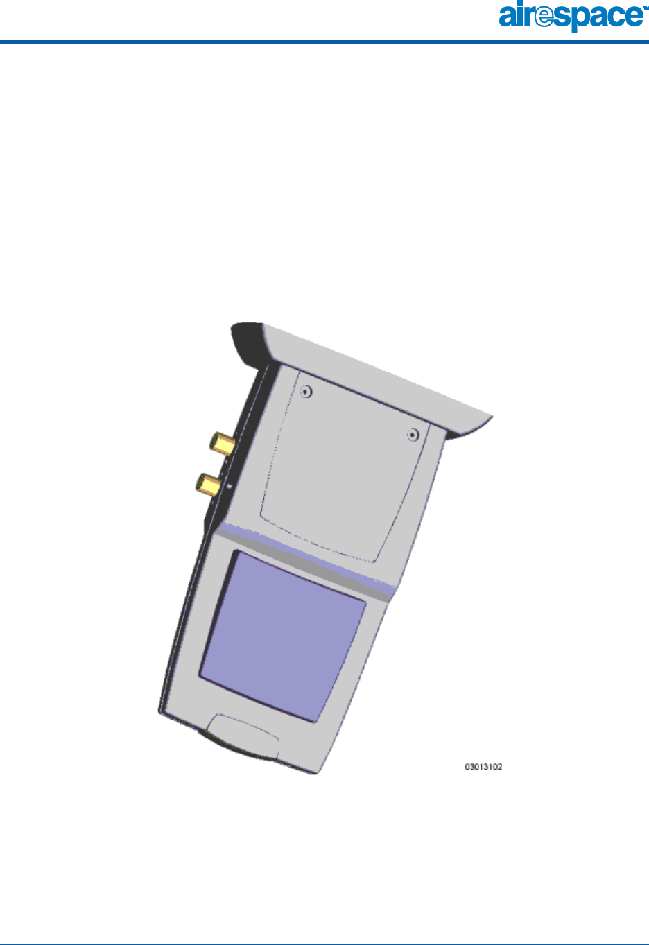
or 802.11b AP functions in a single aesthetically pleasing enclosure. The
following figure shows the Airespace Switch with its ceiling-mount base.
Figure - Airespace AP with Ceiling Mount Base
4/21/03 Airespace Access Point
90-100xxx-000 Airespace AP Installation Guide 3
Note that the Airespace AP is manufactured in a neutral color so it blends into
most environments (but can be painted), contains pairs of high-gain internal
antennas for unidirectional (180-degree) or omnidirectional (360-degree)
coverage (Airespace AP External and Internal Antennas), and is plenum-rated
for installations in hanging ceiling spaces.
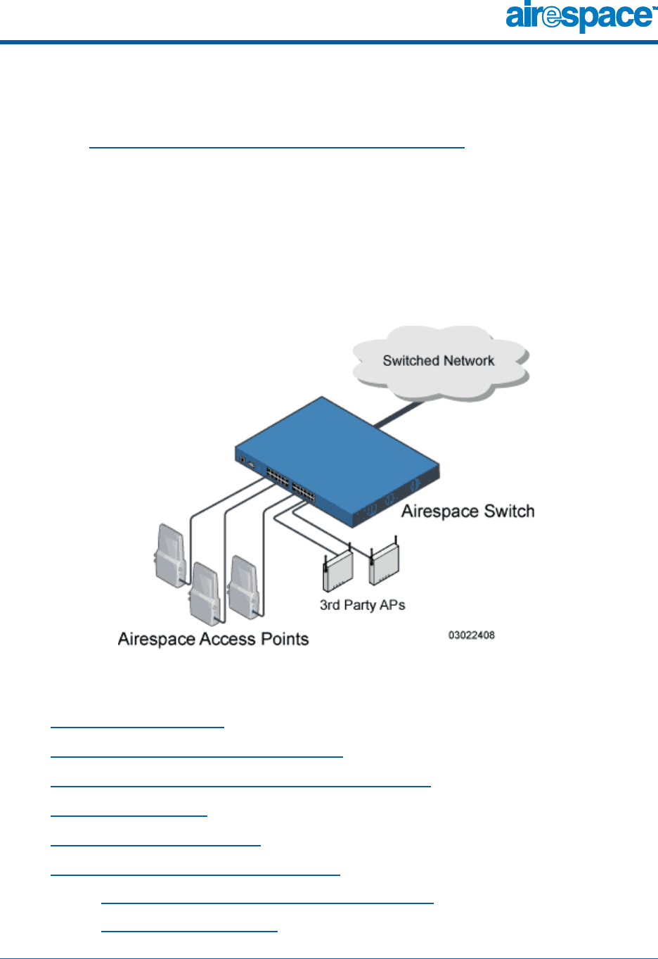
In the Airespace System, most of the processing responsibility is removed
from traditional SOHO (small office, home office) APs and resides in the
Airespace Switch. The following figure shows Airespace APs and Third Party
Access Points connected directly to the Airespace Wireless Switch front panel.
Figure - Airespace Switch and Access Points
Refer to the following for more information on Airespace APs:
•Airespace AP Models
•Airespace AP 802.11a Radio Cards
•Airespace AP External and Internal Antennas
•Airespace AP LEDs
•Airespace AP Connectors
•Airespace AP Power Requirements
-Airespace AP External Power Converter
-Power Over Ethernet


4/21/03 Airespace AP Models
90-100xxx-000 Airespace AP Installation Guide 5
Airespace AP Models
About Airespace AP Models
The Airespace AP includes one 802.11a radio (AS-1200-A), one 802.11b
radio (AS-1200-B), or one 802.11a and one 802.11b radio (AS-1200-AB). As
an added feature, the AS-1200-B Airespace AP can be updated by the
customer with an 802.11a radio, allowing for current 802.11b coverage and
future 802.11a coverage by the same Airespace AP.
The Airespace AP is available in the following configurations:
•AS-1200-A - Airespace AP with one 802.11a radio and two high-gain
internal antennas
•AS-1200-B - Airespace AP with one 802.11b radio and four high-gain
internal antennas; can be upgraded to an AS-1200-AB by adding an
802.11a Radio Card
•AS-1200-AB - Airespace AP with one 802.11a and one 802.11b radio
and four high-gain internal antennas
The following upgrade card is available:
•AS-AP-RC-A - 802.11a Radio Card: Certified professionals can add this
card to an AS-1200-B to create an AS-1200-AB Airespace AP
Refer to Airespace AP 802.11a Radio Cards for information on the
field-installable radio that adds 802.11a capability to an existing 802.11b
Airespace AP.
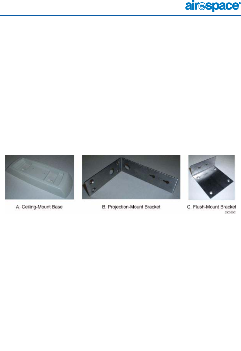
The Airespace AP is shipped with a color-coordinated ceiling mount base, and
projection and flush wall mount brackets. These brackets and base allow
quick mounting to ceiling or wall.
The Airespace can be powered by Power Over Ethernet or by an Airespace AP
External Power Converter. The two power converter models are:
•AS-AP-PWR110 - External 110 VAC-to-48 VDC Power Converter for any
Airespace AP.
•AS-AP-PWR220 - External 220 VAC-to-48 VDC Power Converter for any
Airespace AP.

4/21/03 Airespace AP 802.11a Radio Cards
90-100xxx-000 Airespace AP Installation Guide 6
Airespace AP 802.11a Radio Cards
About Airespace AP 802.11a Radio Cards
The AS-1200-B (802.11b) Airespace AP can be upgraded to an AS-1200-AB
(802.11a and 802.11b) Airespace AP by adding a professionally-installed
802.11a radio card.
The 802.11a radio supports diversity between the internal antennas and an
optional factory-supplied external antenna.
Refer to the Airespace AP 802.11a Radio Card Quick Installation Guide for
professional installer instructions.
Note: No 802.11a external antennas are currently certified or available
in this release. Contact Airespace, Inc. for a list of FCC-approved
802.11b external antennas.

4/21/03 Airespace AP External and Internal Antennas
90-100xxx-000 Airespace AP Installation Guide 7
Airespace AP External and Internal Antennas
About Airespace AP External and Internal Antennas
The AS-1200-A Airespace AP enclosure contains one 802.11a radio which
drives two fully-enclosed high-gain antennas which provide a large
360-degree coverage area. When equipped with an optional factory-supplied
external antenna, the 802.11a radio supports receive and transmit diversity
between the internal antenna and the external antenna.
The diversity function provided by Airespace radios can result in lower
multipath fading, fewer packet retransmissions, and higher client throughput.
Note: The Airespace APs must use the factory-supplied internal or
external antennas to avoid violating FCC requirements and voiding the
user’s authority to operate the equipment. Refer to FCC Statements
for Airespace AP for detailed FCC information.
The AS-1200-AB Airespace AP enclosure contains one 802.11a and one
802.11b radio and four fully-enclosed high-gain antennas which provide large
360-degree 802.11a and 802.11b coverage areas. Note that the 802.11b
radio supports receive and transmit diversity between the internal antennas,
while the 802.11a radio supports diversity between the internal antennas and
an optional factory-supplied external antenna.
The AS-1200-B Airespace AP enclosure contains one 802.11b radio and a slot
for an 802.11a radio card, and four high-gain antennas, which provide large
360-degree 802.11b (and future 802.11a) coverage areas. The 802.11b radio
supports receive and transmit diversity between the internal antennas. Note
that the 802.11a radio supports diversity between the internal antennas and
an optional factory-supplied external antenna.
The Airespace APs have reverse-polarity TNC jacks for installations requiring
factory-supplied external directional or high-gain antennas. The external
antenna option can create more flexibility in Airespace AP and antenna
placement.
Note that the Airespace System supports Antenna Sectorization, which can
be used to increase the number of clients and/or client throughput in a given
air space. Installers can mount two Airespace APs back-to-back and the
Airespace Switch operator can disable the second antenna in both Airespace
APs to create a 360-degree coverage area with two sectors.

4/21/03 Airespace AP LEDs
90-100xxx-000 Airespace AP Installation Guide 8
Airespace AP LEDs
About Airespace AP LEDs
Each Airespace AP is equipped with four LEDs across the top of the case.
They can be viewed from nearly any angle. The LEDs indicate power and fault
status, 2.4 GHz (802.11b) radio activity, and 5 GHz (802.11a) radio activity.
This LED display allows the wireless LAN manager to quickly monitor the
Airespace AP status. For more detailed troubleshooting instructions, refer to
the Troubleshooting the Airespace AP section (to be determined).
4/21/03 Airespace AP Connectors
90-100xxx-000 Airespace AP Installation Guide 9
Airespace AP Connectors
About Airespace AP Connectors
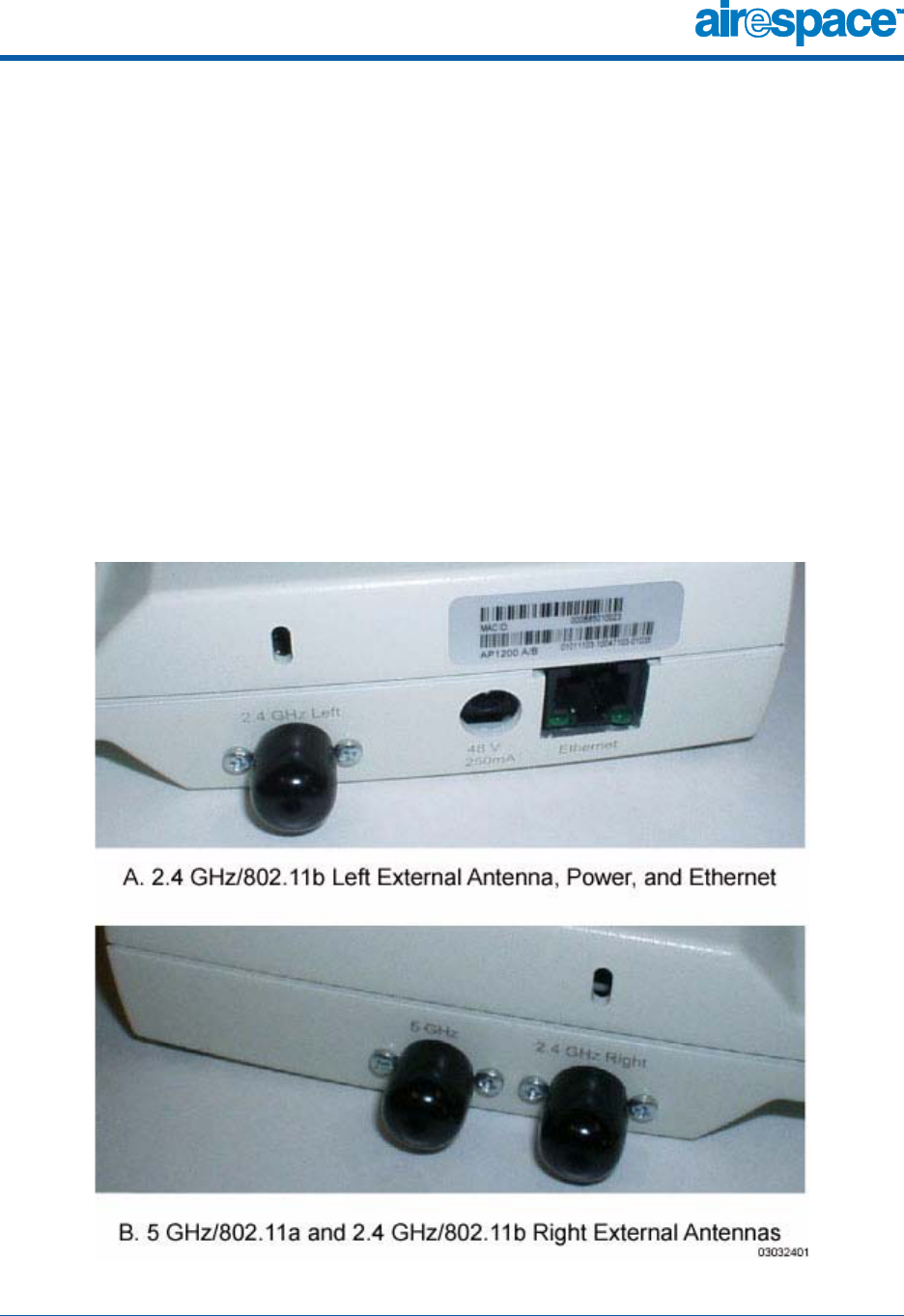
The Airespace AP has the following external connectors:
•One RJ-45 Ethernet jack, used for connecting the Airespace AP to the
Airespace Switch or to the switched network.
•One 48 VDC power input jack, used to plug in an optional
factory-supplied external power adapter.
•Three reverse-polarity TNC antenna jacks, used to plug optional
external antennas into the Airespace AP: two for an 802.11b radio, and
one for an 802.11a radio.
Figure - Airespace AP External Connectors

4/21/03 Airespace AP Connectors
90-100xxx-000 Airespace AP Installation Guide 10
The Airespace AP communicates with an Airespace Switch using standard
CAT-5 (Category 5) or higher 10/100 Mbps twisted pair cable with RJ-45
connectors. Plug the CAT-5 cable into the RJ-45 jack on the side of the
Airespace AP.
Note that the Airespace AP can receive power over the CAT-5 cable from the
Airespace Switch or switched network equipment. Refer to Power Over
Ethernet for more information about this option.
The Airespace AP can be powered from an optional factory-supplied external
AC-to-48 VDC power adapter. If you are powering the Airespace AP using an
external adapter, plug the adapter into the 48 VDC power jack on the side of
the Airespace AP.
The Airespace AP includes two 802.11a and two 802.11b high-gain internal
antennas, which provide omnidirectional coverage. However, the Airespace
AP can also use optional factory-supplied external high-gain and/or direc-
tional antennas, as described in Airespace AP External and Internal Antennas.
When you are using external antennas, plug them into the reverse-polarity
TNC jacks on the side of the Airespace AP as described in the Airespace
Access Point Quick Installation Guide.
Note: The Airespace APs must use the factory-supplied internal or
external antennas to avoid violating FCC regulations and voiding the
user’s authority to operate the equipment, as described in FCC State-
ments for Airespace AP.
4/21/03 Airespace AP Power Requirements
90-100xxx-000 Airespace AP Installation Guide 11
Airespace AP Power Requirements
About Airespace AP Power Requirements
The Airespace AP requires a 48 VDC nominal (between 38 and 57 VDC) power
source capable of providing 7 Watts. The polarity of the DC source does not
matter because the Airespace AP can use either a +48 VDC or a -48 VDC
nominal source.
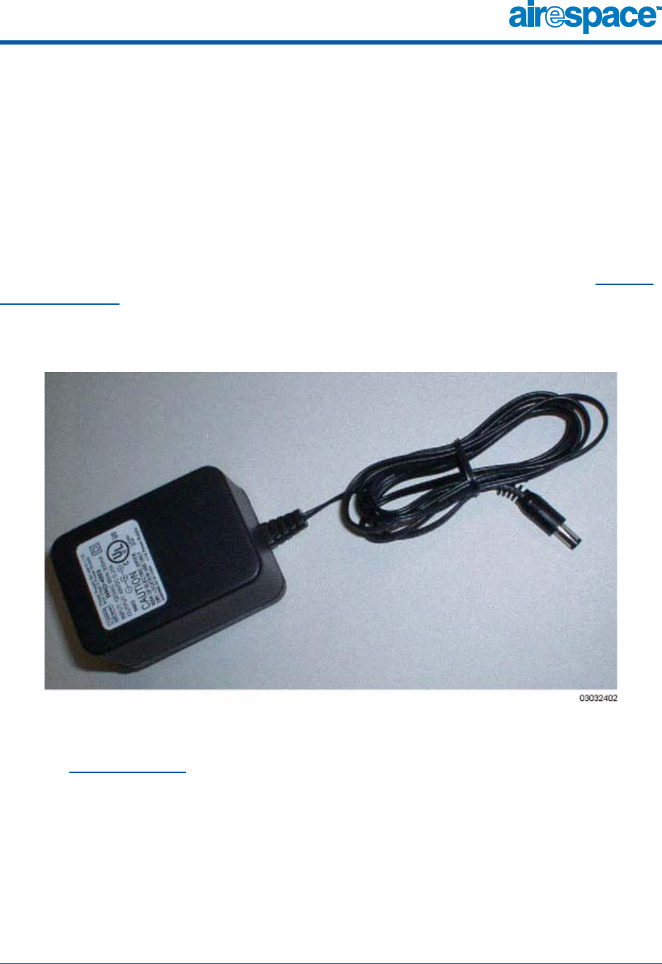
Airespace APs can receive power from an external power converter (see
figure below) plugged into the side of the Airespace AP case, or from Power
Over Ethernet.
Figure - Typical Airespace AP External Power Converter
For more information about the Airespace AP specifications and capacities,
refer to Specifications, to be determined.

4/21/03 Airespace AP External Power Converter
90-100xxx-000 Airespace AP Installation Guide 12
Airespace AP External Power Converter
About Airespace AP External Power Converter
The Airespace AP can receive power from an external 115 VAC-to-48 VDC
power converter or from Power Over Ethernet equipment.
The external power converter plugs into a secure 115 VAC convenience outlet
(to avoid having cleaning personnel unplug the converter when they use
power cleaning equipment). The converter produces the required 48 VDC
output (Airespace AP Power Requirements) for the Airespace AP. The
converter output feeds into the side of the Airespace AP through a 48 VDC
jack (Airespace AP Connectors).

4/21/03 Power Over Ethernet
90-100xxx-000 Airespace AP Installation Guide 13
Power Over Ethernet
About Power Over Ethernet
Airespace equipment supports 802.3af-compliant Power over Ethernet (PoE),
which can reduce the cost of discrete power supplies, additional wiring,
conduits, outlets, and installer time. PoE also frees installers from having to
mount an Airespace Access Point or other powered equipment near AC
outlets, providing greater flexibility in positioning APs for maximum coverage.
When you are using PoE, the installer runs a single CAT-5 cable from each
Airespace AP to the PoE-equipped Airespace Wireless Switch or other network
element, or to a PoE power hub. When the PoE equipment determines that
the Airespace AP is PoE-enabled, it sends 48 VDC over the unused pairs in
the Ethernet cable to power the Airespace AP.
Note: Airespace APs can receive power from the Airespace Switch, or
any other network device conforming to the IEEE 802.3af standard.
Note: Each Airespace AP can also receive power from an Airespace AP
External Power Converter.
The Airespace Switch can be ordered with or without PoE, as required. It can
be ordered with internal PoE or an external PoE hub. Contact Airespace for
recommended external PoE hubs.


4/21/03 Airespace AP Physical Security
90-100xxx-000 Airespace AP Installation Guide 15
Airespace AP Physical Security
About Airespace AP Physical Security
The side of the Airespace AP housing includes a slot for a Kensington Micro-
Saver Security Cable. You can use any MicroSaver Security Cable to ensure
that your Airespace AP stays where you mounted it!
Refer to the Kensington website for more information about their security
products, or to the Airespace Access Point Quick Installation Guide for instal-
lation instructions.

4/21/03 © 2003 Airespace, Inc. All Rights Reserved.
90-100xxx-000
Airespace Access Point Quick Installation Guide
Airespace Access Point Quick Installation Guide
System Release 1.1
Overview
This guide is designed to provide you with the information needed to mount
Airespace Access Points (APs). Airespace APs are part of the innovative
Airespace Wireless Enterprise Platform (Airespace System), and require no
configuration after they are mounted; the end user configures Airespace APs
through the Airespace Wireless Switch.
This document assumes that a site survey has been performed as described
in the Airespace Access Point Site Survey Guide section in the Airespace
Product Guide, that AP locations and mounting options have been selected,
and that you have one Airespace AP per indicated location.
After the site survey is done, you should have a map indicating the following:
•AP locations.
•AP mounting options: in the middle of a ceiling/hallway, in the ceiling
plenum, projecting away from the wall, or flat against the wall.
•AP power options: power supplied by the AC-to-DC power converter
orderable from the factory, or Power over Ethernet (PoE) from the
Airespace Wireless Switch, another switched network device, or a PoE
injector/hub (usually located in a wiring closet).
If you do not have a map, make one so you can return the MAC addresses
from each location to the person who is planning or managing this wireless
network.
Refer to the following sections to install the Airespace APs.
Note: When mounting Airespace APs, make sure to maintain a 20 cm
(8 in.) separation between the Airespace APs and bystanders to
comply with FCC RF exposure regulations. Refer to the FCC State-
ments section in the Airespace Product Guide for more FCC
information.


4/21/03 Step 1: Collecting Required Tools and Supplies
90-100xxx-000 Airespace Access Point Quick Installation Guide 3
Step 1: Collecting Required Tools and Supplies
Step 1: Collecting Required Tools and Supplies
•One Airespace AP per location.
•AP Mounting Kits, factory-supplied with each Airespace AP.
•Optional external AC-to-DC power converter, factory-orderable.
•Optional external 802.11b antennas.
Note: No 802.11a external antennas are currently certified or available
in this release. Contact Airespace, Inc. for a list of FCC-approved
802.11b external antennas.
•Map showing AP locations, and mounting and power options.
•Screwdrivers, drills, and ladder.
•An assortment of sheet metal and drywall screws and toggle bolts.
•CAT-5 (or higher) cables to connect the Airespace AP locations and the
Airespace Wireless Switch or switched network device.
•Optional Kensington MicroSaver Security Cable to secure each
Airespace AP.
Continue with Step 2: Preparing Mounting Locations.
4/21/03 Step 2: Preparing Mounting Locations
90-100xxx-000 Airespace Access Point Quick Installation Guide 4
Step 2: Preparing Mounting Locations
Step 2: Preparing Mounting Locations
On your map, you should have the AP locations, mounting options, and power
options.
•Find the required mounting locations.
•Use the appropriate mounting bases and/or brackets to mark the wall
or ceiling locations for sheet metal, drywall, or other screws. Make sure
you leave enough space around the APs and brackets to plug the CAT-5
cable, optional external antenna cable(s), optional power converter
cable, and optional Kensington MicroSaver Security Cable into the sides
of the APs.
Figure - Factory-Supplied Mounting Brackets
•If necessary, drill holes for the various cables where they can be mostly
hidden from casual view. When you are mounting the AP using a
projection-mount L-bracket (the one with two long legs) the cables can
be routed through the 5/8-inch (15.9 mm) holes in the bracket.
•Route the CAT-5, optional power converter, optional external antenna
cable(s), and optional Kensington MicroSaver Security cables to where
they can plug into the AP. Make sure to leave about 6 inches (15 cm) of
slack in the cables for future modifications.
•Attach the brackets to the wall or ceiling, or install screws for
ceiling-mount base:
-Where you are going to use the projection-mount or flush-mount
bracket, use customer-supplied sheet metal, drywall, or other
screws to attach the bracket to the ceiling or wall.

4/21/03 Step 2: Preparing Mounting Locations
90-100xxx-000 Airespace Access Point Quick Installation Guide 5
-Where you are going to use the ceiling-mount base, install cus-
tomer-supplied sheet metal, drywall, or other screws with 1/4
inch (6.35 mm) or smaller heads protruding from the ceiling
about 0.1 inch (2.5 mm).
You are now ready to install the Airespace APs. Continue with Step 3:
Mounting the Airespace APs.

4/21/03 Step 3: Mounting the Airespace APs
90-100xxx-000 Airespace Access Point Quick Installation Guide 6
Step 3: Mounting the Airespace APs
Step 3: Mounting the Airespace APs
Using the mounting kits supplied with each Airespace AP, mount each
Airespace AP in its indicated location, oriented as shown on the map. Note
that you can mount the Airespace APs in the ceiling plenum or below the
ceiling, but the APs perform best when mounted below the ceiling.
Note that the Airespace System supports Antenna Sectorization, which can
be used to increase the number of clients and/or client throughput in a given
air space. Installers can mount two Airespace APs back-to-back and the
Airespace Switch operator can disable the second antenna in both Airespace
APs to create a 360-degree coverage area with two sectors.
The Airespace APs can be mounted in one of three configurations:
•Ceiling Mount
•Projection Wall Mount
•Flush Wall Mount
4/21/03 Ceiling Mount
90-100xxx-000 Airespace Access Point Quick Installation Guide 7
Ceiling Mount
Ceiling Mount
When you are mounting the AP in the middle of a ceiling (flat sides toward
the room or hallway), use the ceiling-mount base to mount the AP as shown
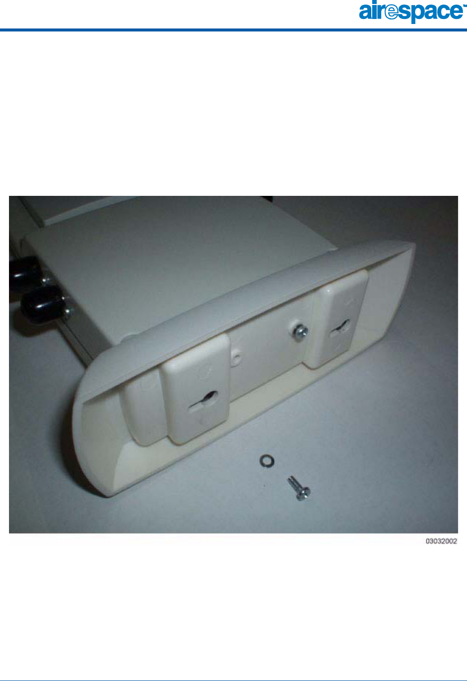
in the following figure and as described below:
Figure - Assembling the Airespace AP and Ceiling-Mount Base
•Copy the MAC address(es) from the label(s) on the AP onto the corre-
sponding location on the map. MAC addresses have the format
000B85xxxxxx.
•Attach the ceiling-mount base to the bottom of the AP using the
factory-supplied machine screws and washers.

4/21/03 Ceiling Mount
90-100xxx-000 Airespace Access Point Quick Installation Guide 8
•Position the ceiling-mount base so its keyhole slots are partly on the
drywall, sheet metal, or other screw heads installed in Step 2:
Preparing Mounting Locations.
Note: If the screws do not securely hold the ceiling-mount base,
remove the AP and adjust the screws until they hold the ceiling-mount
base securely.
•Attach the cables to the sides of the AP.
Note: When the AP is powered up and is associated with an Airespace
Wireless Switch (Green/Power and Yellow/802.11b and/or Yellow/
802.11a LEDs lit), the AP is broadcasting its beacon signal(s). When
this happens, complete the installation as quickly as possible to
remove yourself from within 8 inches (20 cm) of the AP to comply with
FCC RF radiation exposure guidelines.
•Slide the ceiling-mount base onto the drywall, sheet metal, or other
screw heads until it snugs into place.
You have installed the Airespace AP. Repeat Step 3: Mounting the Airespace
APs for each AP location, and then continue with Step 4: Returning MAC
Information.
4/21/03 Projection Wall Mount
90-100xxx-000 Airespace Access Point Quick Installation Guide 9
Projection Wall Mount
Projection Wall Mount
When you are mounting the AP out from a wall (flat sides along the wall or
hallway), use the projection-mount L-bracket.
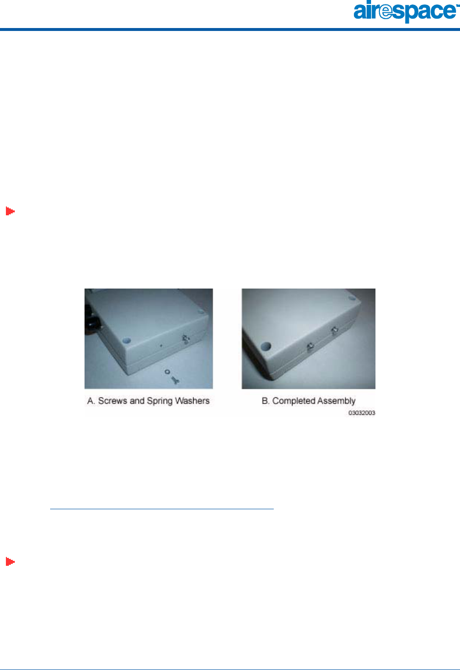
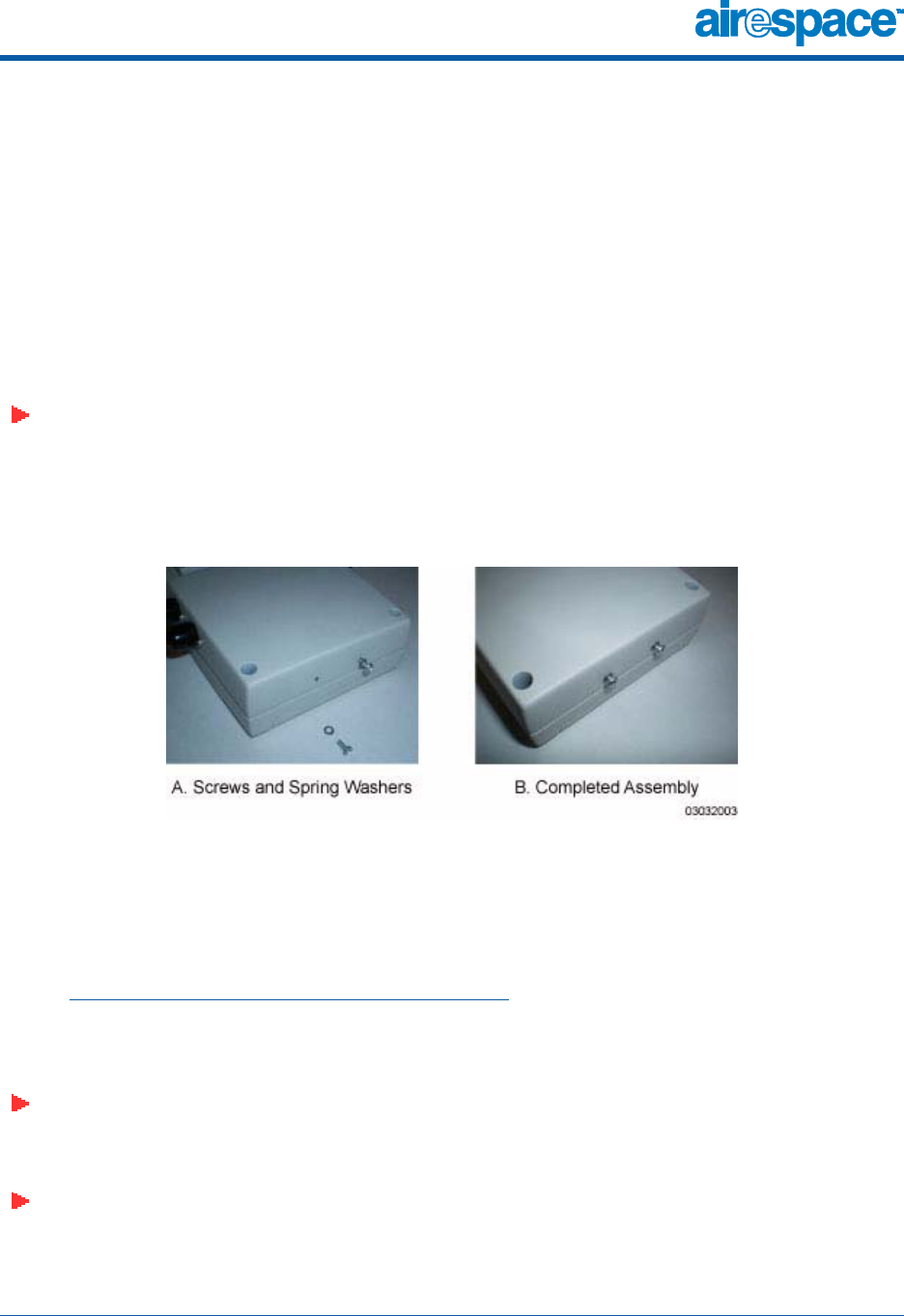
•Before proceeding, gently screw the two factory-supplied screws and
spring washers into the bottom of the Airespace AP. Make sure the
spring washers have their convex (high center sections) pointing
toward the screw heads.
Note: The Airspace AP threaded holes have precision-depth threads. Do
not overtighten the screws, or the bracket will not fit under the screw
heads.
Figure - Assembling the Mounting Screws and Spring Washers to the Airespace AP
•Copy the MAC address(es) from the label(s) on the AP onto the corre-
sponding location on the map. MAC addresses have the format
000B85xxxxxx.
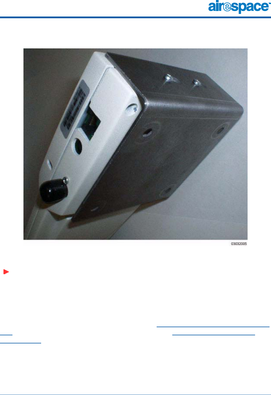
•You have already attached the projection-mount L-bracket to the wall
in Step 2: Preparing Mounting Locations.
Slide the screws into the keyhole slots on the mounting bracket as
shown in the following figure.
Note: If the screws do not securely hold the bracket, remove the AP
and adjust the screws until they securely hold the bracket.
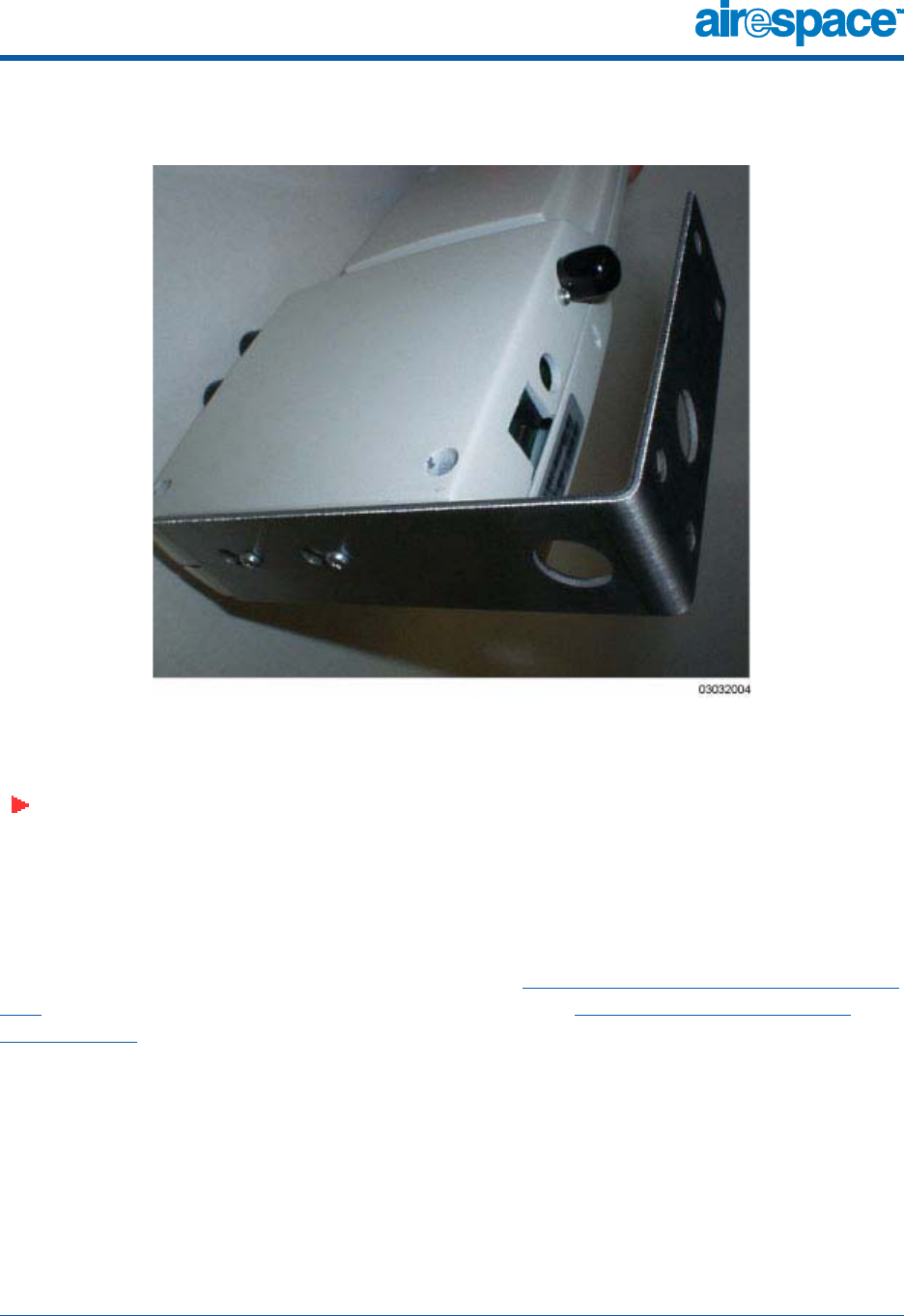
4/21/03 Projection Wall Mount
90-100xxx-000 Airespace Access Point Quick Installation Guide 10
Figure - Assembling the Airespace AP to the Projection-Mount Bracket
•Attach the cables to the sides of the AP.
Note: When the AP is powered up and is associated with an Airespace
Wireless Switch (Green/Power and Yellow/802.11b and/or Yellow/
802.11a LEDs lit), the AP begins broadcasting its beacon signal(s).
When this happens, complete the installation as quickly as possible to
remove yourself from within 8 inches (20 cm) of the AP to comply with
FCC RF radiation exposure guidelines.
You have installed the Airespace AP. Repeat Step 3: Mounting the Airespace
APs for each AP location, and then continue with Step 4: Returning MAC
Information.
4/21/03 Flush Wall Mount
90-100xxx-000 Airespace Access Point Quick Installation Guide 11
Flush Wall Mount
Flush Wall Mount
When you are mounting the AP against a wall (flat side toward the inside of
the building), use the flush-mount bracket.
•Before proceeding, gently screw the two factory-supplied screws and
spring washers into the bottom of the Airespace AP. Make sure the
spring washers have their convex (high center sections) pointing
toward the screw heads.
Note: The Airspace AP threaded holes have precision-depth threads. Do
not overtighten the screws, or the bracket will not fit under the screw
heads.
Figure - Assembling the Mounting Screws and Spring Washers to the Airespace AP
•Copy the MAC address(es) from the label(s) on the AP onto the corre-
sponding location on the map. MAC addresses have the format
000B85xxxxxx.
•You have already attached the flush-mount bracket to the wall in
Step 2: Preparing Mounting Locations.
Slide the screws into the keyhole slots on the mounting bracket as
shown in the following figure.
Note: Make sure the side of the AP with the door is facing away from
the wall. This ensures that the correct antenna is facing the building,
and makes future upgrades easier.
Note: If the screws do not securely hold the bracket, remove the AP
and adjust the screws until they securely hold the bracket.
4/21/03 Flush Wall Mount
90-100xxx-000 Airespace Access Point Quick Installation Guide 12
Figure - Assembling the Airespace AP to the Flush-Mount Bracket
•Attach the cables to the sides of the AP.
Note: When the AP is powered up and is associated with an Airespace
Wireless Switch (Green/Power and Yellow/802.11b and/or Yellow/
802.11a LEDs lit), the AP begins broadcasting its beacon signal(s).
When this happens, complete the installation as quickly as possible to
remove yourself from within 8 inches (20 cm) of the AP to comply with
FCC RF radiation exposure guidelines.
You have installed the Airespace AP. Repeat Step 3: Mounting the Airespace
APs for each AP location, and then continue with Step 4: Returning MAC
Information.

4/21/03 Step 4: Returning MAC Information
90-100xxx-000 Airespace Access Point Quick Installation Guide 13
Step 4: Returning MAC Information
Step 4: Returning MAC Information
When you have completed the installations as outlined in Step 3: Mounting
the Airespace APs, return the MAC addresses and their locations on the maps
or floorplans to the network planner or manager. The Airespace Control
System (ACS) software operators will use the MAC address and location infor-
mation to create maps for precise wireless LAN management.
Also return any unused mounting kit hardware and external power converters
to the network planner or manager for use in future deployments.
Note: Network Planner or Manager, now is a good time to register your
Airespace APs at www.airespace.com.

4/21/03 Planning Notes
90-100xxx-000 Airespace Access Point Quick Installation Guide 14
Planning Notes
Planning Notes
Note: This product is certified for indoor deployment only. Do not
install or use this product outdoors.
About Cables
•You will run one CAT-5 Ethernet cable from the AP to the Airespace
Switch, another switched network device, or a PoE injector/hub.
When the AP will be mounted below the ceiling using the ceiling mount
or wall mount brackets, you may have to drill a hole into the ceiling ple-
num to run the CAT-5 cable to the wiring closet. When the CAT-5 cable
cannot be run through the ceiling plenum, find another path to route
the cable from the AP to the wiring closet.
When the AP will be mounted above the ceiling using the ceiling mount
or wall mount brackets, run the CAT-5 cable to the wiring closet
through the ceiling plenum. When the CAT-5 cable cannot be run
through the ceiling plenum, find another path to route the cable from
the AP to the wiring closet.
•When you are powering the AP from AC power, route the power
converter cable from the AC convenience outlet to the AP. Make sure
you secure the AC power plug so it will be difficult for people to pull on
the power cord or unplug the power converter from the AC power
outlet.
•When you are powering the AP from a PoE source (Airespace Switch,
another switched network device, or a PoE injector/hub), you do not
need to route a separate power cable to the AP, because the AP will
receive its power across the CAT-5 Ethernet cable. Return the power
converter to the wireless network planner/manager.
About External Antennas
•Refer to the Airespace AP External and Internal Antennas section for an
overview of the external 802.11a and 802.11b external antennas
available for use with the Airespace APs.
Note: No 802.11a external antennas are currently certified or available
in this release. Contact Airespace, Inc. for a list of FCC-approved
802.11b external antennas.
4/21/03 Planning Notes
90-100xxx-000 Airespace Access Point Quick Installation Guide 15
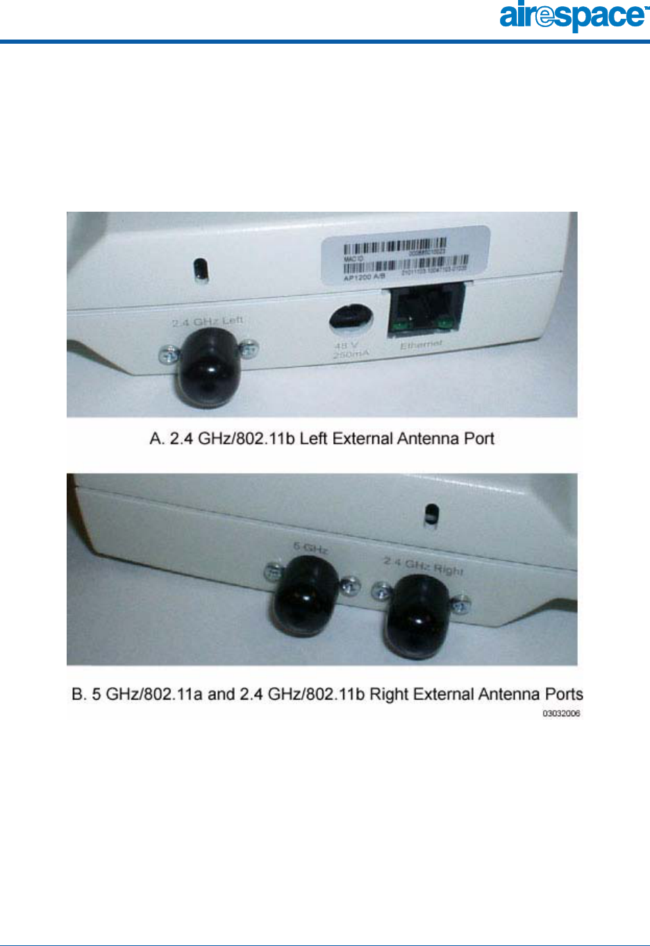
•When you are attaching external antennas to the Airespace AP, use
cables with reverse-TNC connectors to connect antennas to the ports
on the side of the Airespace AP. See the following figure for antenna
port markings.
Figure - Airespace AP External Antenna Port Markings

4/21/03 Planning Notes
90-100xxx-000 Airespace Access Point Quick Installation Guide 16
About Mounting Options
Note: Because the Airespace AP internal antennas have been designed
to reduce inter-floor interference, it is strongly recommended that you
mount the AP standing or hanging straight up or down.
Note: You can mount the Airespace APs in the ceiling plenum or below
the ceiling using the ceiling mount base or wall mount brackets, but
the APs perform best when mounted below the ceiling.
•When you are mounting the AP in the middle of a ceiling, hallway, or
ceiling plenum, you will typically use the color-coordinated
ceiling-mount base to stabilize the AP after it is mounted. Use the
mounting base to mark the sheet metal, drywall, or other screw
locations.
The mounting base attaches to the bottom of the AP with two supplied
screws, and then the assembly slides and locks onto two sheet metal,
drywall, or other screws.
•When you are mounting the AP out from a wall (flat sides along the
room or hallway), use the projection-mount L-bracket supplied with the
AP. Use the L-bracket to mark the sheet metal, drywall, or other screw
locations.
•When you are mounting the AP against a wall (flat side toward the
inside of the building), use the flush-mount bracket supplied with the
AP. The flush-mount L-bracket is the one with one long and one short
leg. Use the L-bracket to mark the sheet metal, drywall, or other screw
locations.
About Physical Security
Regardless of mounting, the Airespace AP can be secured with a Kensington
MicroSaver Security Cable. If required, use any MicroSaver Security Cable to
attach either side of your Airespace AP to a solid beam, pipe, or support.