Airgun Designs 68 Automag Users Manual D3MANUAL.P65
2015-09-01
: Airgun-Designs Airgun-Designs-68-Automag-Users-Manual-804345 airgun-designs-68-automag-users-manual-804345 airgun-designs pdf
Open the PDF directly: View PDF ![]() .
.
Page Count: 13

Instruction
Manual
Level 7

- 2 - - 3 -
AIRGUN DESIGNS, INC.
804 Seton Court
Wheeling, Illinois 60090
USA
Telephone: 847-520-7507
Tech Support: 847-520-7225
Fax: 847-520-7848
68AUTOMAG and MINIMAG are Registered Trademarks of Airgun Designs, Inc.
Micro C/A and 6-Pak+ are trademarks of Airgun Designs, Inc.
Several trademarks and Registered trademarks appear in this manual. The companies
listed below own the marks following their names:
CM Support: ViewLoader. Worr Game Products: Sniper
© Airgun Designs, Inc., 1998

- 4 - - 5 -
Table of Contents
Warranty..................................................................................... 6
Safety ......................................................................................... 8
Fast Start.................................................................................... 8
First Time Problems ................................................................... 9
History and Theory of Design ................................................... 10
Performance ............................................................................. 12
Lubrication ................................................................................ 12
Velocity Adjustment .................................................................. 12
Constant Air Tanks ................................................................... 13
Field Stripping........................................................................... 13
Cleaning and Maintenance ....................................................... 14
Paintballs .................................................................................. 14
Liquid in the Valve .................................................................... 15
Loader ...................................................................................... 15
Barrel........................................................................................ 16
O-Rings .................................................................................... 16
Nubbin ...................................................................................... 16
On/Off Valve ............................................................................. 16
Power Tube .............................................................................. 17
Diagram of Valve Internals ....................................................... 18
Regulator Valve ........................................................................ 19
Blow-Off Valve.......................................................................... 19
Re-Assembly of Valve .............................................................. 19
Re-Assembly of Body ............................................................... 20
Updates .................................................................................... 20
Accessories .............................................................................. 20
Troubleshooting ................................................................... 20-24
WARNING: This is not a toy. Misuse/careless use may
cause serious injury or death. Eye protection designed
specifically for paintball use must be worn by the user and
any person within 200yds(183m). Read Operation Manual
before using.

- 6 - - 7 -
Parts not manufactured by Airgun Designs
In evaluating in-house repairs, we have found that about 20% of the time we
are fixing problems caused by modifications and/or aftermarket accessory parts
installed in our markers. In most cases we must replace these aftermarket parts
with our own parts to make the marker work again. We are sure you can see
that this is very unfair to us and eventually to you in higher prices. We will no
longer fix markers for free either under the limited warranty or the punch
card warranty if the marker has an aftermarket part and/or accessory that
causes a problem. Some examples of modifications and/or parts that can
cause problems include: painted mainbodies, two finger triggers, wooden grips,
aftermarket o-rings, aftermarket seals, aftermarket bolts, aftermarket on/off
assemblies and aftermarket trigger frames.
In many cases, aftermarket accessories such as barrels, expansion chambers
and grip frames do not cause a problem and will not void the warranty. Many
aftermarket parts and accessories are available. We have no problem with
aftermarket parts being installed in our markers. However, please keep your
stock parts on hand and replace them first if you have problems with your
marker. If you are still having problems when all the original parts are installed,
then call us for assistance or to arrange for your marker to be sent to us for
repair. *****Return Authorization Required*****
We have always required that you call and get a return authorization number
before you send in your marker. This is for your safety and insures a speedy
repair. With an RA number we know your name and address, the problem, and
the date promised as soon as the marker arrives at our factory. If a marker
comes in without an RA number someone has to track down the owner, find out
what’s wrong, and then enter the information in the computer system. Therefore,
we will no longer accept repairs without an RA number. Packages without
RA numbers clearly marked on the outside of the package will be returned
to the sender! Technical Support
Our technical support hotline (847-520-7225) will not change. Technical
support is available by telephone any time from 9:00 a.m. until 11:30 a.m. and
1:00 p.m. until 4:30 p.m. (Central Time) on Mondays through Fridays. Please
note that our telephone lines are busiest on Mondays and Fridays. Please have
your serial number ready so that we can look up your file quickly. Send in your
warranty card so we will have you on file when you call.
Our Commitment
Here at Airgun Designs we want to continue our long history of producing
quality products and providing quality service. Airgun Designs is focusing on
giving you, the player, the best possible value for your money. We hope that this
new policy reflects our commitment to you, the player, now and into the future.
Tom Kaye
President
WARRANTY
Congratulations on the purchase of your new Airgun Designs marker! There
have been some important changes in the way Airgun Designs handles warranty
repair work, so please read this thoroughly.
In the past, Airgun Designs produced markers of the highest quality and
provided premium service by fixing most markers for free. We charged a
correspondingly high price for this combination of quality and service. In
reviewing our policies and realizing that the majority of players in today’s
paintball world are on a limited budget, we have changed both our pricing and
warranty policies. In the past, by charging a higher price and repairing markers
for free, we rewarded the people who did not take the time to fix or maintain the
markers while excluding the people on a more limited budget.
We are reducing the prices significantly on most of our product line to make
them more affordable to the majority of the paintball public in 1998. We don’t
have to tell you that when you reduce the selling price something else has to go
to reduce the cost. WE DID NOT REDUCE THE QUALITY OF OUR PRODUCT
IN ANY WAY in order to reduce the selling price to our customers. The marker
you purchased today is the same in every way as the markers we produced in
the past. The only thing that has changed is the warranty policy.
Our New Warranty Policy
We now offer a 90 day limited warranty from the date of original retail pur-
chase. This warranty covers parts, labor, manufacturing defects, and malfunc-
tions. It does not cover abuse such as wrapping the gun around a tree when you
lose a game nor does it cover damage that occurs as part of an accident such as
a house fire.
After the 90 day limited warranty ends we now have what we call the punch
card warranty program. There is no actual punch card, but there are one to four
stars laser engraved above the serial number on your marker’s valve assembly.
Each star entitles you to a free repair of your marker. When you send your
marker in for repair we will remove one star and so “punch” your card. After we
have punched a star there is a 30 day warranty to ensure we fixed your marker
properly. If the marker still has the same problem it was sent in for we will fix it
again without punching another star as long as the marker is returned to us
within 30 days.
Once the stars are used up we will still service your marker, but we will charge
you a standard rebuild fee which covers the replacement of soft parts and return
ground shipping. There will be additional charges for hard parts such as bolts or
sear assemblies. Just as there is a 30 day warranty of repairs done under the
punch card program, there is also a 30 day warranty on rebuild repair work. This
punch card warranty program is good for three years from the date of manufac-
ture. In this way you can save the punches for times when you really have a
problem and we will be happy to fix it for you.

- 8 - - 9 -
full lock. The regulator nut is on the back of the valve body and requires only one
turn to adjust from 200 to 300 fps. Air venting out of the back of the regulator
indicates that the internal blow-off valve is responding to over pressure in the
system and the velocity should be turned down.
Field stripping is accomplished by unscrewing the field strip screw underneath
the frame after removing the air supply. THE TRIGGER MUST BE PULLED TO
SLIDE THE VALVE BODY OUT. There is a locking pin for alignment in the
regulator body which allows the valve body to only come out part way before you
must twist the valve body clockwise to continue sliding out the back. Reinstall in
the same manner. Once removed, the entire valve and bolt assembly is available
for cleaning.
Maintenance on all active o-rings can be accomplished without tools. See
specific headings for valve body disassembly.
When adjusting the regulator nut, shoot several times before chronoing to allow
the regulator piston and spring to seat properly. Always start below your in-
tended velocity and work your way up. When firing the paintball marker, it’s
important to remain aware of how many balls are in your loader. If the quantity
runs too low the slight blowback past the bolt will bobble the balls in the feed
tube, thus preventing a positive ball feed. This increases the likelihood of ball
breakage.
Always use high quality, fresh paintballs. The blow forward action aggressively
pushes the ball into the barrel before firing and we have found that lower grades
of paint cannot withstand the acceleration.
A slide-on sight rail is available from your local dealer or Airgun Designs, Inc.
FIRST TIME PROBLEMS
There are several first time problems to watch out for. Many times the paintballs
will not feed because the recoilless design does not jiggle the loader. You must
remain aware enough to keep the balls feeding.
Next, the bolt can stick forward causing the trigger to lock due to either paint
chips wedging between the bolt and breech or, when degassing the paintball
marker, caused by turning off the tank and shooting those last few blooping
shots. When the bolt sticks forward the trigger will not come forward. Remove
the barrel and push the bolt back until the trigger clicks forward.
The paintball marker will give very little indication that it is running out of gas; by
the time you see the velocity drop you are 20-30 shots away from total shut-
down. Additionally, if you use a constant air tank with an on/off valve make sure
you open it all the way. The same is true for pin valves; you must rotate the tank
at least one full turn after initial gas up or the tank will not feed enough air.
DO NOT USE A SIPHON TANK. IT WILL NOT WORK AND WILL MOST LIKELY
DAMAGE THE PAINTBALL MARKER!!
SAFETY
THIS PAINTBALL MARKER IS NOT A TOY! This paintball marker should be
treated as a dangerous instrument and should always be treated with respect.
Never point a paintball marker at anyone not properly attired. If misused or
improperly maintained, this paintball marker can cause serious bodily injury,
including blindness, or even death. Please read all safety instructions and
directions in this manual
before
using this paintball marker.
Do not point or shoot this paintball marker at animals. Do not point or shoot this
paintball marker at any person unless you and your target are engaged in
paintball activities and are wearing proper safety gear including approved
paintball goggles, mask, and pads. Follow all maintenance instructions carefully.
If you are unsure about any aspect of the maintenance procedures, contact your
local dealer or the Airgun Designs, Inc. Tech Line at (847) 520-7225.
This paintball marker is always armed and cocked when an air supply is in-
stalled. Always use the safety located behind the trigger on the grip when an air
supply is attached or installed. Disengage the safety only when on a playing field
and the game has started. The safety is off and the paintball marker
will
fire
when the red ring of the safety pin is showing.
Always chronograph this paintball marker before using it. Never shoot this
paintball marker when the chronograph readings exceed 300 feet per second!
There is a blow-off valve incorporated into the valve mechanism that will release
air pressure if pressure exceeds a predetermined amount. This blow-off valve is
factory set and is not user adjustable.
Always remove the air supply from the paintball marker and dry fire in a safe
direction before disassembling. The velocity adjusting nut is on the back of the
regulator body. Do not disassemble the velocity adjusting nut while the paintball
marker is under pressure. If air is leaking out the back of the velocity regulator
nut the paintball marker is over-pressurized and will shoot at a higher than
intended velocity. Reduce the regulated pressure by backing off the velocity
regulator nut and re-chronograph the paintball marker. If problems persist call
your dealer or Airgun Designs, Inc. Do not put your fingers into the breech
area or down the ball feed tube while firing the paintball marker!
The pressure regulator allows gas under pressure to push the trigger forward
after shooting. An excessively hard trigger pull may indicate the system is
overpressurized. Do NOT fire a paintball marker that has excessively hard trigger
pull; call your local dealer or Airgun Designs, Inc. immediately.
FAST START
This is a quick overview of how to use the 68AUTOMAG/MINIMAG™ for the
experienced player. Introducing air pressure to the paintball marker will charge
and cock the system. The system is a blow forward from open bolt, similar in
concept to a cork in a champagne bottle.
The barrel utilizes a twist lock mount; a one-quarter twist is all that is required for

- 10 - - 11 -
This was a tough list but the team, undaunted, used the two years of accumu-
lated knowledge and evaluated sixteen different combinations of valves and
bolts and focused on what was soon to become P3. We knew that pressure in
the tank could vary as much as 100% and the only way to get everything
consistent was to incorporate a pressure regulator that would provide consistant
velocity and infinite velocity adjustment. Second, any air not coming out behind
the ball would be wasted and would be coming from a hole that would allow dirt
in. Third, a light weight bolt for good efficiency combined with a trigger mecha-
nism that did not try to stop the bolt while it was moving all resulted in a totally
new design for us and the sport of paintball.
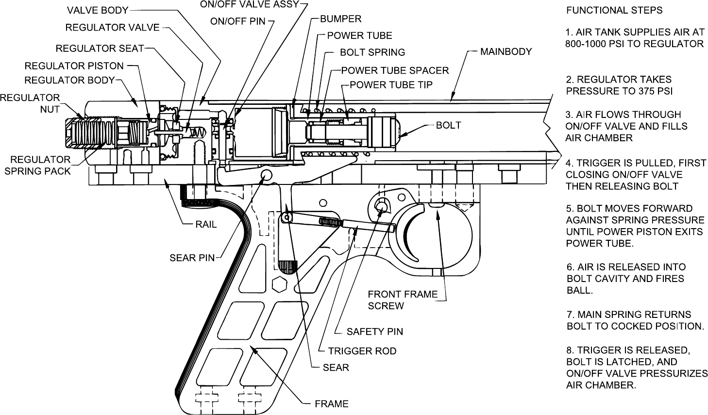
The paintball marker you have just purchased is P4, a further refined version of
P3. Its function can be broken down into three independent stages: regulation,
chamber fill, and chamber dump. Stage one occurs when an air source is
connected to the paintball marker and the system builds up pressure. At a
predetermined pressure, set by the regulator nut, the regulator valve closes, thus
sealing off the air source from the rest of the paintball marker. The pressure
inside the paintball marker is now approximately 400 psi even though CO2 tank
pressure may vary from 600-1000 psi under different temperatures. Stage two
happens when the trigger is released, opening the ON/OFF VALVE and allowing
the air chamber to fill to a regulated pressure of 400 psi.
Stage three is where everything happens. The air chamber is designed like a
champagne bottle with a cork (the bolt) stuck in the opening. The cork (or bolt, in
this case) wants to pop out, but is held in place by the sear. When you pull the
trigger the sear first closes the ON/OFF VALVE (just before releasing the bolt)
shutting off the air chamber from the regulator. This gives the paintball marker a
precise amount of regulated air charge. Next the sear releases the bolt and, like
the cork, it starts moving forward out of the bottle(power tube). At some point
after the ball has been pushed into the barrel, the cork leaves the end of the
bottle and all the air rushes out. Once the air is gone the BOLT SPRING which
has been collapsed from the bolt moving forward pushes the BOLT back into the
now empty air chamber. The process starts over when the trigger is released.
As with all designs, nothing is perfect and there are some inadequacies in this
design. All pressure regulators, by the nature of their design, cannot fill a
chamber instantly but must fill most of it quickly and then taper off to hit the
desired pressure. (You do the same when pouring a glass of water.) When firing
faster than three shots a second, the air chamber will not be fully filled and you
will experience a 10-20 fps drop in average velocity. The other problems revolve
around CO2 itself. We usually think of CO2 in terms of a liquid or a gas, but in
reality it also takes the form of “steam.” CO2, like water, boils when heated and
becomes steam; the steam will still exist as a form of “humidity” until its tempera-
ture is above 87 degrees. Pressure changes will also cause water or CO2 to boil,
but this is usually less understood by the general public. Everyday examples of
water boiling caused by pressure are cavitation by boat propellers (boiling
caused by low pressure) and car radiators (not boiling caused by high pressure).
What does this mean to your average paintball player? Simple! When you shoot
HISTORY AND THEORY OF DESIGN
The 68AUTOMAG/MINIMAG is the result of three years of development from the
Airgun Designs research team. At the 1988 Poconos tournament we displayed
our first semi-auto prototype, the PANTHER. The PANTHER was a blowback
single-barrel design that was very advanced for its time. The paintball marker
design and prototype were sold, but never produced.
The second, completely new paintball marker was developed during the follow-
ing year and was code named P2 (for PANTHER #2). It was a blowback design
that featured interchangeable barrels, no tools takedown to all seals, and
reduced parts count. During this time we saw a tremendous improvement in
pump paintball marker technology, giving the players field strip capability,
doubling efficiency, and reducing weight. We knew that players would not be
content with a semi-auto that simply shot when you pulled the trigger if it did not
also meet the performance they had come to expect from their pump paintball
markers.
After two years of research and development, we knew there were two inherent
problems with a blowback design. First, while the heavy bolt being blown back
was necessary to slow the action down, it reduced efficiency. The heavier the
bolt, the more energy it consumed; lightening the bolt made it harder for the bolt
to open the valve far enough. The second fundamental problem was in allocating
how much energy went to blow back the bolt (requiring a fixed amount) versus
propelling the ball (variable with tank pressure and velocity setting). With all of
our blowback designs velocity was dependent on tank pressure which caused
velocity to drop when firing enough to chill the tank down.
The semi-auto firearm from which the blowback design comes has a relatively
fixed energy source (gunpowder) which burns the same no matter what the
temperature, humidity, etc. There has not been a semi-auto firearm made that
can shoot a clip of bullets all at the same velocity with only half the powder in
some shells.
After two years, it was with some disappointment that we closed the book on our
blowback designs and wiped the drawing board clean. We knew what our
customers wanted and after the successes of the MICRO-C/A™, 6-PAK+™ and
the TURBO VALVE, we didn’t want a letdown. Starting fresh, the team took a
“bottoms up” approach in starting with a list of performance specifications and
then coming up with the design. The specifications list was as follows:
Light weight
Pistol size for one handed use
No tools takedown
High efficiency
Interchangeable barrels
Consistant velocity
Infinite velocity adjustment
No internal parts exposed
No premature parts breakage

- 12 - - 13 -
rapidly, the pressure in your tank drops causing the CO2 to boil, the steam goes
into your paintball marker’s air chamber, you fire the paintball marker discharging
the air chamber behind the ball (dropping pressure again), the steam boils into
gas (steam is still a liquid and boils into 30 times its volume in gas) and the ball
velocity varies. Switch tanks and you now have warm steam going into a cold
paintball marker and, just like the mirror in the bathroom, you get liquid condens-
ing in the paintball marker.
PERFORMANCE
The paintball marker will get a minimum of 400 good shots from a 7 oz. CO2 tank
under normal conditions. An eleven inch barrel gives the best efficiency; longer
or shorter barrels will reduce these numbers.
Cold weather performance (below 50°) on CO2 will be poor. Since the paintball
marker is designed to function at a predetermined pressure, outside tempera-
tures below freezing will not generate enough CO2 tank pressure for adequate
velocity. If you regularly play in these conditions, we recommend that you invest
in a quality high pressure system (i.e. compressed air or nitrogen setup).
Take-up is the movement of the trigger before it comes in contact with the sear,
after sear contact continuing to pull through fires the paintball marker. The trigger
in the 68AUTOMAG/MINIMAG has been designed to have a “snap” action with
no take-up to give the shortest possible stroke and thus the highest possible
firing rate. The average person can fire 4-5 shots per second but, when charged
with adrenaline, this can climb to 6 per second. Note that the loader can only
feed 7 balls per second under ideal conditions, so be careful!
LUBRICATION
We find that customers who properly lubricate their paintball markers once a
week have the fewest problems. To lubricate your 68AUTOMAG/MINIMAG
properly, drip 4-6 drops of AUTOLUBE into the air inlet closest to the valve. Then
gas up and dry fire the paintball marker several dozen times with the barrel
removed (to prevent oil build-up in the barrel).
In addition, once a month remove the valve body and spray oil into the holes
marked -OIL-. You may also use automotive grease (i.e. wheel bearing or any
light grease) on the spring pack and Regulator Piston O-ring.
VELOCITY ADJUSTMENT
The velocity of your 68AUTOMAG/MINIMAG is adjusted by increasing or
decreasing the regulated pressure. This is accomplished by turning the REGU-
LATOR NUT located on the back of the regulator body. Only a minimal amount
of rotation is necessary to adjust the velocity. We recommend that you always
start at a low velocity setting and turn the adjustment screw clockwise to your
desired setting.
Always shoot several shots to seat the regulator piston and spring. High veloci-
ties will cause the blow-off valve built into your system to vent air out the back of
the regulator body. If you ever hear air venting, stop and re-chrono the paintball
marker immediately. We find the best performance to be in the 270-280 fps
range. Occasionally grease the threads of the regulator nut.
We offer an optional 3-piece Tournament Cap that is designed to prevent the
regulator nut from backing out and thereby reducing velocity under severe
playing conditions.
CONSTANT AIR TANKS
DO NOT USE A SIPHON TANK ON YOUR PAINTBALL MARKER!!!
Liquid CO2 in this paintball marker will cause all the active o-rings to leak and the
velocity will not be controllable. Make sure the tank valve is feeding air into the
paintball marker fast enough when rapid firing; make sure the valve is completely
open. Paintball markers that dramatically lose velocity often have this problem.
For vertical tank and remote vertical tank setups, always use standard tanks that
have been weight checked to ensure proper fills. Horizontal tanks should be anti-
siphon. Contact your local dealer for information on an anti-siphon tank.
The vertical bottle adapter is an accessory for the 68AUTOMAG and a standard
feature on the MINIMAG. It helps reduce the possibility of the paintball marker
“going liquid” by mounting the standard air tank vertically.
When using CO2, steps must be taken to keep liquid from entering the valve. The
most effective setup we can recommend is a full size expansion chamber
vertically mounted in front of the trigger frame and a remote tank. The hose
would run from the A.I.R. valve to a vertical adapter mounted on the bottom of
the rail, in front of the trigger frame. The expansion chamber screws into the
adapter just like a tank. A hose would then run from the bottom of the chamber
to remote tank positioned vertically on your back (in a pouch, on your belt?).
Many people who do not like remote tanks mount their tanks horizontally off the
bottom of the trigger frame or main rail. Any horizontal tank should be anti-
siphon. Anti-siphon tanks are tailored to specific adapters. They are setup for,
and cannot be interchanged with other CA adapters. Remote tanks should be
standard (Neither siphon nor anti-siphon).
Overall, remote tanks are more effective because they are vertical. Keep in mind
that no setup is 100% effective in keeping liquid CO2 out.
Below 50oF freezing will still occur, even with an expansion chamber and remote.
If you plan on playing in cold weather, seriously consider a high pressure
system.
FIELD STRIPPING
Field stripping the 68AUTOMAG/MINIMAG is accomplished by first degassing
and removing the air supply, then unscrewing the knurled field strip screw at the

- 14 - - 15 -
rear of the frame. To remove the valve body you must FIRST pull the trigger and
THEN pull the valve body out. The valve body has a pin that slides in a Z-shaped
slot in the rail. To remove the valve body pull it straight back 1/4 inch, rotate the
valve body slightly(being careful to keep the 68AUTOMAG logo aligned). The
valve body should then pull straight out the back, opening the paintball marker
for cleaning.
CLEANING AND MAINTENANCE
To quickly clean the paintball marker without disassembly simply use a bucket of
clean water and swish the paintball marker body in it WHILE THE PAINTBALL
MARKER IS FULLY PRESSURIZED! Keeping the paintball marker pressurized
keeps the water out of the internal workings of the valve body. After hard use the
paintball marker should be taken down and all exposed parts cleaned and
inspected for wear or problems. Lightly lubricate all surfaces and re-assemble
according to instructions. To deep clean your paintball marker start by field
stripping down to the valve body. Remove and clean the POWER TUBE O-RING
(see POWER TUBE section), lightly lubricate and reinstall. Then remove and
clean the REGULATOR VALVE and REGULATOR SEAT (see REGULATOR
VALVE). The spring on the REGULATOR VALVE will catch particles of debris
that come from your fill tank. Always clean the spring thoroughly; pay particular
attention to the sealing edge that contacts the REGULATOR SEAT. The REGU-
LATOR SEAT should be cleaned carefully and inspected for eny embedded
particles; these particles can cause the regulator to leak slowly and can also
cause the gun to shoot hot.
Install with the wide end ot the REGULATOR SEAT in first (see REGULATOR
VALVE). With the REGULATOR BODY off, unscrew the REGULATOR NUT
completely and remove the SPRING PACK; it will fall out. Use a paper clip to
push the REGULATOR PISTON out by inserting the paper clip wire through the
REGULATOR SEAT hole in the other end of the REGULATOR BODY. Clean the
REGULATOR PISTON, lubricate and reinstall (see RE-ASSEMBLY OF VALVE).
PAINTBALLS
There are many different kinds of paintballs on the market, all with different
specifications. The one thing that is consistent is that low quality paintballs will
perform poorly in the 68AUTOMAG/MINIMAG. Always use fresh, high quality
paintballs and try many different types and colors to find the best type suited for
your paintball marker and playing conditions.
A common problem that we are all concerned about is ball breakage. Ball
breakage was the one area we spent the most time on in the 68AUTOMAG/
MINIMAG’s development. There are two ways balls break in your paintball
marker: first, because the ball did not feed all the way into the breech and was
cut in half by the bolt; this is addressed in the LOADER section and is not a
concern here. Second is the impact from the air blast. Because the paintball
marker can shoot twice as much paint in the course of a game it will appear that,
on a per game basis, you are breaking twice as many balls. Our trials show that
a properly setup paintball marker shooting quality paint will break approximately
3-4 paintballs per thousand. In comparison, low quality paint will break 1 in 50. A
good test for shell strength is to drop several hundred paintballs one at a time
from a height of 6 feet. Balls that consistently survive 6-7 bounces are consid-
ered fresh; balls that break within 3 bounces are either stale or have weak shells.
If you know the paintball marker is setup properly and you still experience
problems, switch to a different brand or color and try again.
LIQUID IN THE VALVE
Liquid CO2 can enter the air chamber of an airgun and when expelled into the
barrel behind the ball it instantly boils into gas that is many times the volume of
the liquid. This causes a hotter than normal shot and, depending on the volume
of liquid, can show velocity readings in excess of 350 fps. This action is known
as supercharging and is extremely dangerous and should be avoided at all
times. The blow-off valve will not protect against supercharging because
the liquid is at the normal pressure when it is in the air chamber! To
prevent supercharging follow these basic rules: 1) never shoot the paintball
marker at the ground since this allows the liquid to run straight into the valve; 2)
never overfill a bottle since a higher than normal liquid level will drain fluid into
the valve; 3) keep your paintball marker at outside temperature because a cold
valve body allows liquid to remain in its liquid state instead of boiling into gas.
In addition, we have found that putting a warm bottle on a cold paintball marker
causes the warm CO2 vapor to enter the air chamber where it condenses into
liquid; this is identical to freezing down a 7 ounce tank before filling from the
warmer 50 pound tank — avoid this.
LOADER
When you receive your 68AUTOMAG PowerFeed or MINIMAG you also receive
a free ViewLoader™ and elbow. Always keep at least twenty balls in the loader
when fast firing. This will keep the balls from being blown up into the loader from
the bolt blowback. The blowback WILL help the balls feed when the hopper is
full.
Ball breakage is common with first time users of the 68AUTOMAG/MINIMAG due
to the recoilless action and the tendency of the balls to hand in the loader.
Become aware of the need to shake the paintball marker to keep the balls
flowing and listen for the balls bobbling telling you to reload. If you find that the
balls are cut in half in the breech, look at the loader or your technique.
Some elbows used with the ViewLoader will require smoothing out on the inside
for maximum flow; make sure that there are no sharp corners or edges to catch
balls on. The most reliable firing method is tri-burst until you become accus-
tomed to keeping the balls feeding.
- 16 - - 17 -
BARREL
The barrel on your 68AUTOMAG PowerFeed and MINIMAG is made from the
same aluminum stock as the famous Bud Orr Sniper™, long known for its
accuracy. The barrel lock is a stainless detent pin mounted in the paintball
marker rail. To remove the barrel, twist the barrel counter clockwise one-quarter
turn and pull straight out. To reinstall slide the barrel up to the stop; then, while
exerting steady pressure, rotate the barrel to find the detent slot and continue to
push straight in and then rotate clockwise into the detent position. The o-rings on
the barrel serve to give the barrel a friction fit; they do not seal air pressure.
O-RINGS
The o-rings in your 68AUTOMAG/MINIMAG are all high quality 90 durometer
urethane or teflon for long life and abrasion resistance. Replace any damaged o-
rings with Airgun Designs, Inc. supplied replacements.
O-rings should only be lubricated with Autolube.
NUBBIN
Airgun Designs barrels utilize a wire nubbin to retain the paintball in the breech
and to prevent double feeding. The wire nubbin will automatically compensate
for all size balls and should give long life if not abused. If double feed problems
develop, bend the wire so it protrudes slightly further into the bore. When
properly installed, each nubbin should protrude about the thickness of a
matchbook cover into the breech.
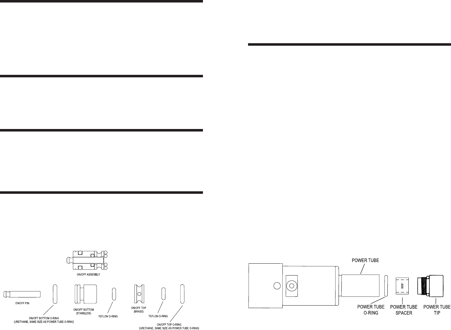
ON/OFF VALVE
The ON/OFF VALVE assembly is located on the bottom of the valve body and is
actuated by the back end of the sear. Its function is to shut off airflow to the air
chamber when firing and recharge the chamber when the trigger is released. It
consists of three parts: the ON/OFF TOP, the ON/OFF BOTTOM, and the ON/
OFF PIN (see diagram below).
There are four o-rings in the assembly: two in the top of the valve body hole (one
inside the other) and two more on the ON/OFF BOTTOM. There is an assembly
diagram laser engraved on the valve body to show the proper assembly order.
There are two small and two large o-rings in the assembly; only the small teflon
o-ring in the bottom of the valve body is an active o-ring. The small active teflon
o-ring can be swapped with its teflon double.
POWER TUBE
The Level 7 marker incorporates a POWER TUBE that is welded on to the air
chamber. There is a blue urethane bumper at its base to keep the bolt from
impacting the valve body on its return stroke. The brass POWER TUBE TIP is
screwed into the front of the power tube and is prevented from unscrewing by a
urethane o-ring seated in its base. It is important that this POWER TUBE TIP is
tightened properly to avoid stripping the POWER TUBE TIP threads. To remove,
use a coin to unscrew the insert from the POWER TUBE. Directly underneath
the POWER TUBE TIP is the POWER TUBE SPACER and beneath that is the
POWER TUBE O-RING. The POWER TUBE O-RING is an active seal that
receives substantial abuse and should be inspected for wear regularly. It is 90
durometer urethane and should only be replaced with an identical replacement.
If you need to replace it on the field, the o-rings in the ON/OFF VALVE are the
same, giving you two potential spares to swap out.
Problems with the POWER TUBE O-RING occur when the paintball marker is
not kept lubricated or when liquid CO2 passes through the system creating ice
crystals that prevent the o-ring from sealing. Insufficient lubrication or ice causes
spontaneous barrel leaks that are usually short lived but are an annoyance in the
field. If ice is causing the barrel leak, continuing to fire will only prolong the
problem; you must pause long enough to warm up the o-ring. An unlubricated o-
ring will usually re-seal itself within several shots. If the barrel continues to leak
and the action of the moment does not allow you to make repairs, hold the
trigger back to stop the leak. When ready to fire, release and fire quickly; holding
the trigger back after each shot, or during any pause. This method will give you
reduced velocity, but will keep you in the game.
REMEMBER when reinstalling the POWER TUBE parts: O-ring first, POWER
TUBE SPACER next, and then the POWER TUBE TIP.(See diagram below)
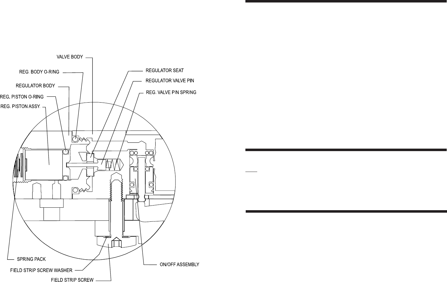
- 18 - - 19 -
REGULATOR VALVE
The REGULATOR VALVE is the heart of the system. It is accessed by unscrew-
ing the VALVE BODY (which has the air inlet) from the REGULATOR BODY
(which has the velocity adjusting nut). Once unscrewed, you will find the REGU-
LATOR VALVE and SPRING protruding from the VALVE BODY.
The REGULATOR VALVE and SPRING are held in by spring pressure and can
be pulled out as one unit. On the REGULATOR BODY you will see a urethane
washer(REGULATOR SEAT) snapped inot its hole; this is the most critical seal
in the marker and must be inspected regularly and kept completely clean. If this
seal leaks the paintball gun goes full pressure, the trigger gets hard, and the
BLOW-OFF VALVE vents out the rear of the gun. Paintball markers venting out
the BLOW-OFF VALVE usually have dirt on this seal; to prevent problems,
regularly wipe this seal with a clean cloth. To reassemble, snap the REGULA-
TOR SEAT back in its hole; it will only snap in and stay one way, but it can be
reversed and carefully reassembled if a problem develops. Next push the
REGULATOR VALVE and SPRING assembly back in its hole in the VALVE
BODY until the 68AUTOMAG/MINIMAG logo lines up. If you forget how the parts
go together, there is a diagram laser engraved on the VALVE BODY showing the
correct relationship of the REGULATOR VALVE and the REGULATOR SEAT.
BLOW-OFF VALVE
The BLOW-OFF VALVE is self contained in the REGULATOR PISTON and is
NOT user adjustable. It is a safety device for venting air from the paintball
marker if abnormally high pressure occurs in the regulator or air chamber. It is
factory set to vent automatically at 650 psi. Occasional short bursts of air venting
out the VELOCITY ADJUSTING NUT usually means that liquid was present in
the system; this liquid boiled, causing increased pressure and was vented off.
Always check your velocity any time the BLOW-OFF VALVE has vented.
RE-ASSEMBLY OF VALVE
Assuming you have all the valve parts identified in front of you, begin with the
REGULATOR BODY (rearmost end of paintball gun). Find the REGULATOR
PISTON (brass 1/2” round with o-ring) and insert o-ring end first into the back of
the REGULATOR BODY followed by the SPRING PACK, large washer first(looks
like a bunch of washers stacked on a pin). Next screw in the REGULATOR
ADJUSTING NUT finger tight to complete the back end of the paintball gun. On
the end of the REGULATOR BODY that has threads and a large o-ring snap in
the REGULATOR SEAT, which completes the subassembly.
Next, find the VALVE BODY (air inlet on one side) and the ON/OFF VALVE
parts. Insert the ON/OFF VALVE parts according to the diagram on the VALVE
BODY: large and small o-rings first, ON/OFF TOP next, ON/OFF BOTTOM
(small stainless part with two o-rings) and finally the ON/OFF PIN (silver pin 1/8”
diameter, 3/4” long). The REGULATOR VALVE ASSY(small silver pin with large
head and small coil spring) goes into its hole (central hole in VALVE BODY) with
the spring end entering the hole first. The REGULATOR BODY can now be
screwed into the VALVE BODY until the logo lines up.
- 20 - - 21 -
Finally, reassemble the POWER TUBE end. Find the POWER TUBE O-RING
(cream-colored 1/4” OD) and place it into the POWER TUBE, followed by the
POWER TUBE SPACER (small brass ring) and finally the POWER TUBE TIP.
Tighten the POWER TUBE TIP as tight as possible with a coin to complete the
assembly. Don’t forget to slide the BUMPER over the POWER TUBE until it rests
against the VALVE BODY.
RE-ASSEMBLY OF BODY
First set the mainbody on the rail, lining up the “pem”(spot welded) nut into its
hole in the rail. Next fit the trigger frame assembly up to the rail. Carefully feed
the TRIGGER ROD into the trigger frame until it pokes out behind the trigger.
The rod must be fed in from back to front finding its way underneath the safety
pin; when properly installed you should see the tip of the pin from the side of the
paintball gun about midway down the trigger. To finish the frame sub-assembly,
screw in and tighten the front frame screw firmly with the supplied 1/8” allen
wrench.
The assembled VALVE BODY and BOLT can now be slid into place in the back
of the mainbody being careful to line up the logo on the valve, and lock pin in the
rail. The final step is to tighten the FIELD STRIP SCREW and your marker is
ready to go.
UPDATES
We are constantly pushing the leading edge of paintball marker technology and
are continuing to make refinements in our paintball markers. As a service to our
customers, we offer updates to Level 7 for Level 5 and Level 6 markers at no
charge. Please note that all 68AUTOMAGS since serial number CF3456 and
ALL MINIMAGS have been built as Level 7. The update from Level 6 to Level 7
reduced ball breakage by enlarging the air chamber to function at a lower
pressure.
ACCESSORIES
Call your local dealer or Airgun Designs, Inc. at (847) 520-7507 for information
on replacement parts or factory produced accessories for the 68AUTOMAG/
MINIMAG series of paintball markers.
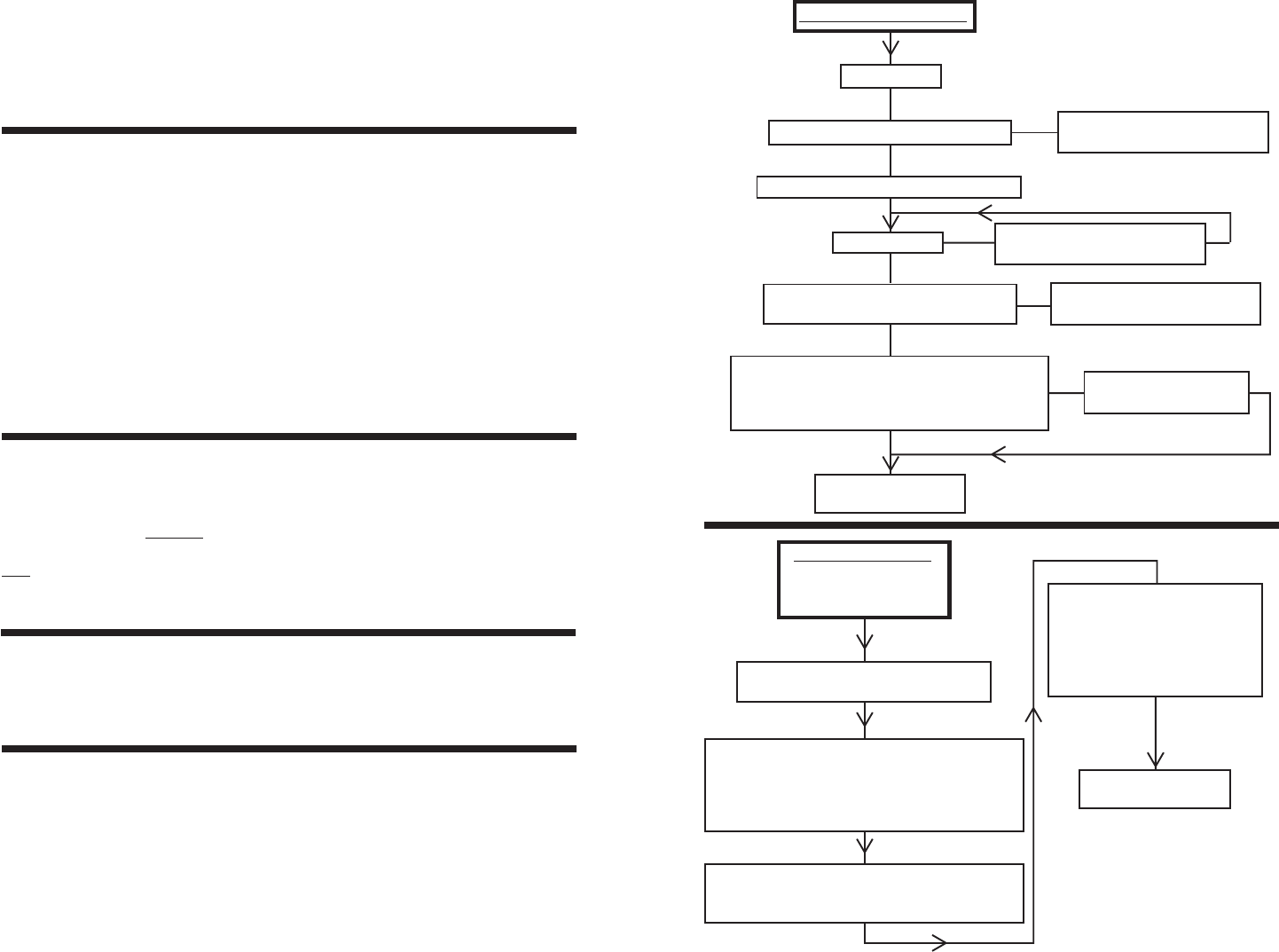
TROUBLESHOOTING
Does marker shoot at all? If not go to debug chart on following page.
Does marker exhibit erratic velocity? Debug chart on following page.
Does marker shoot but exhibits shootdown? Debug chart on page 22.
Does marker leak? Debug chart on page 23.
Is tank full?
Is regulator nut turned in far enough?
Are obstructions cleared from air supply?
Is bolt sticking?
Does trigger have pressure and spring
back when pulled?
Check for proper gap between:
1) Trigger & rod; 2) Trigger & frame
(before fire gap) (after fire gap)
1/16” 1/16”
Call AGD Tech Line
847-520-7225
Turn nut in until marker shoots
or vents out back
YES
YES
YES
YES
YES
YES
NO
NO
Install next size longer power
tube spacer
Field strip marker and check bolt for
foreign objects/obstructions
Adjust trigger rod to
proper gap
NO
MARKER WON’T SHOOT
First shot in a string of shots hot:
Replace Regulator Seat.
Velocity gradually drops off:
(Possible reg. nut backing out)
Make visual mark on regulator nut and check
how far it has backed out after play.
Install 3-piece Tournament Cap.
Reg. Piston/Piston o-ring problem:
Replace Reg. Piston o-ring and apply (common
automotive) grease to o-ring and Spring Pack.
ERRATIC VELOCITY
Shot to shot inconsis-
tency not explained by
shootdown Spring Pack Binding:
Disconnect air source, screw
reg. nut inward until it stops;
then back out reg. nut until
loose again, reattach air source,
and re-chrono marker.
Call AGD Tech Line
847-520-7225
NO
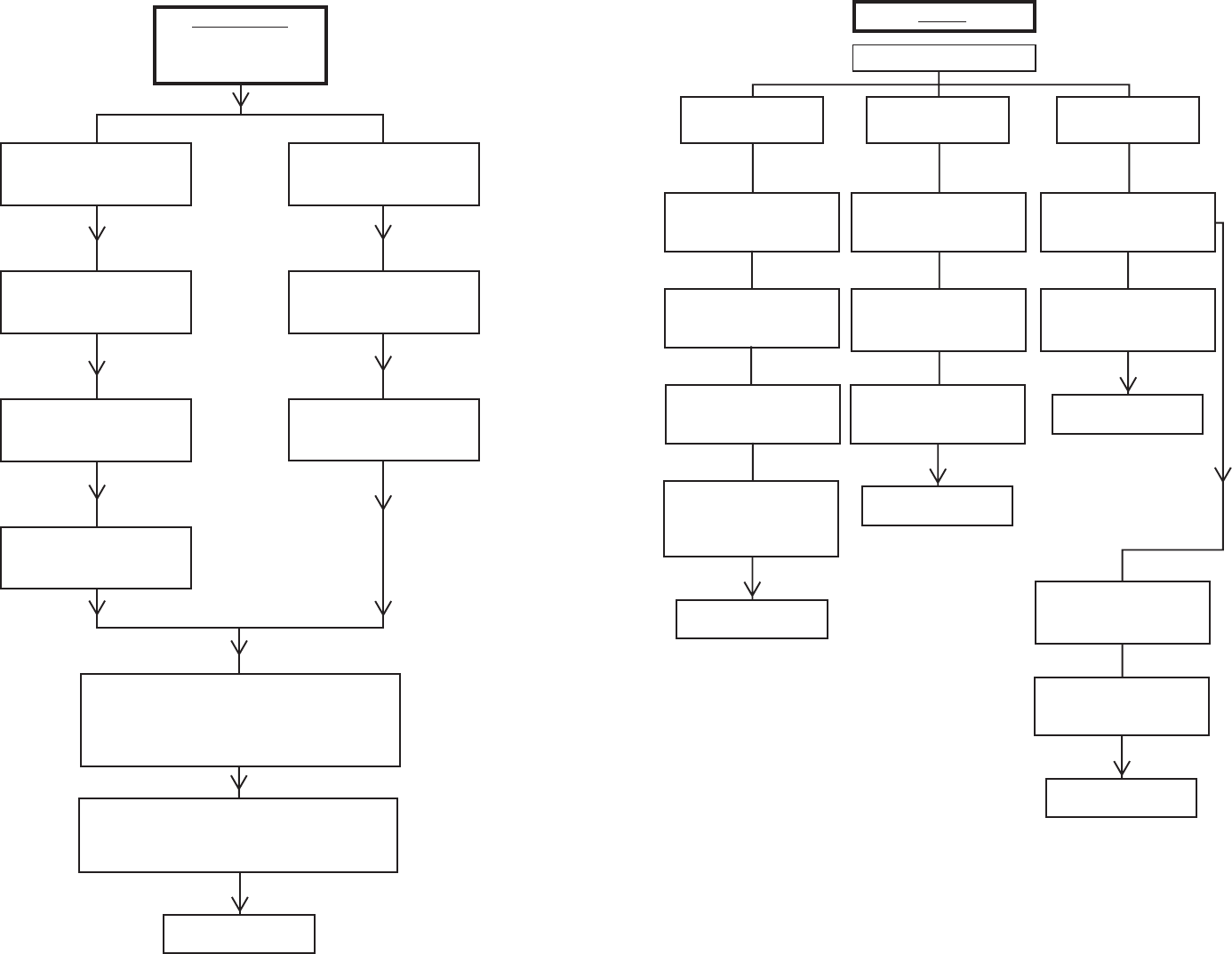
LEAKS
SHOOTDOWN
Velocity drops off
rapidly under rapid
fire
“Short Stroking” trigger may cause shootdown--
be sure trigger is allowed to travel completely
forward after each shot
Check for proper gap between:
1) Trigger & rod; 2) Trigger & frame
(before fire gap) (after fire gap)
1/16” 1/16”
Call AGD Tech Line
847-520-7225
CO2
System Compressed Air or N2
System
Make sure tank valve/pin
valve fully open
Check for line restrictions
such as crushed/clogged
filter, kinked hose, etc.
Ensure liquid CO2 not
getting into valve
Is tank valve fully open and
output pressure set to
800 psi?
Is supply tank filled
to over 800 psi?
Determine leak location
Down the barrel of
the marker Out the back of the
marker In the trigger area
Possible PT o-ring failure:
Replace PT o-ring.
Still leaks?
Poss. incorrect spacer:
Try shorter PT spacer.
Still leaks?
Poss. bolt problem:
Try a different AGD bolt.
Still leaks?
Poss. PT base crack:
Examine area carefully
using magnifying glass.
Still leaks?
Call AGD Tech Line
847-520-7225
Possible Reg. Seat failure:
Replace Reg. Seat.
Still leaks?
If using HP system:
Using a HP piston assy.? If
not, install HP piston assy.
Still leaks?
Possible Piston failure:
Replace Reg. Piston assy.
Still leaks?
Call AGD Tech Line
847-520-7225
Isolate location of leak:
Fire marker & hold trigger back.
Still leaks?
On/Off Top leak:
Replace both o-rings in On/Off
Top area (above the Brass On/
Off Top). Still leaks?
Call AGD Tech Line
847-520-7225
YES
On/Off Bottom leak:
Replace both o-rings in On/Off
Bottom (Stainless piece).
Still leaks?
On/Off Pin failure:
Replace On/Off Pin.
Still leaks?
Call AGD Tech Line
847-520-7225
NO
- 24 - - 25 -
