Airorlite Communications 50289BA8470DL Downlink Booster Amplifier User Manual Revised
Airorlite Communications, Inc. Downlink Booster Amplifier Users Manual Revised
Users Manual Revised

Rhein Tech Laboratories, Inc. Client: Airorlite Communications, Inc.
360 Herndon Parkway Model: 50289 Bi-Directional Booster
Suite 1400 Standards: FCC Part 90
Herndon, VA 20170 FCC ID: UT650289BA8470DL
http://www.rheintech.com Report Number: 2007151A
45 of 71
Appendix J: Manual
Please refer to the following pages for the installation manual.

50289‐BA‐8‐PA
N:\netdrive\FCC\UserManual.doc
‐1‐
8Channel400MHzBi‐Directional
BoosterAmplifier
Model50289‐BA‐8‐PA
OperationsandInstallation
InstructionManual
AIRORLITEUNCONDITIONALLYGUARANTEESTHEMERCHANDISEPROVIDEDAGAINSTDEFECTSOFANYKIND
INCLUDING,WITHOUTLIMITATION,DEFECTSINOPERATION,DESIGN,MATERIALS,ANDWORKMANSHIPFORTWO
YEARSFROMTHEDATEOFDELIVERY.AIRORLITEISNOTRESPONSIBLEFORANYEQUIPMENTREPAIREDOR
ALTEREDBYPERSONSNOTAUTHORIZEDBYAIRORLITEORNOTINACCORDANCEWITHINSTRUCTIONSFURNISHED
BYAIRORLITE.AIRORLITEISNOTRESPONSIBLEFOREQUIPMENTRENDEREDDEFECTIVEASARESULTOFMISUSE,
IMPROPERREPAIR,ORABNORMALCONDITIONSOFOPERATION,NORDOESAIRORLITEASSUMEANYLIABILITYFOR
ANYCONSEQUENTIALDAMAGECAUSEDBYSUCHEQUIPMENT.
SERVICECONTRACTSORCUSTOMERASSISTANCEAGREEMENTSAREAVAILABLEFORAIRORLITEPRODUCTSTHAT
REQUIREMAINTENANCEAND/ORREPAIR.AIRORLITEALSOHASSERVICEANDCONSULTATIONCONTRACTSFOR
ENTIRESYSTEMCONFIGURATIONS.
SYSTEMSPECIFICATIONS

50289‐BA‐8‐PA
N:\netdrive\FCC\UserManual.doc
‐2‐
Description SPECIFICATIONS
FrequencyRange470‐490MHz
OutboundSignal‐Uplink(#ofchannels=8)
(Uplinkchannelcardscanbeprogrammedtothesefrequenciesonly)
InboundSignal‐Downlink(#ofchannels=8)
(Downlinkchannelcardscanbeprogrammedtothesefrequenciesonly)
ChannelBandwidth(Uplink/Downlink) 25kHzNominal
ChannelSpacing 25KHz
RFFrequencyAccuracy Tracksinputsignalexactly
AdjacentChannelSelectivity 70dB@±17.5kHzFc
RFOutputPower(Downlink) +25dBm/carrier,minimum
RFOutputPower(Uplink) +26dBm/carrier,minimum
VariationofOutputPowerw/InputLevel +0,‐1.0dBineitherdirection
MaximumPassbandRippleAcrossFullBand 2dB
MaximumPassbandRippleAcrossany100kHzsegment 0.1dB
AmplifierInputPorts(nodamage) 0dBm
PropagationDelay <120microseconds,maximum
Intermodulation/CrossmodulationDistortionatFullOutputPower ‐60dBc
ChanneltoChannelIsolation ‐70dBm
MinimumHighBandSignaltoproduce+25dBmoutputtoRadiatingAntennaCable ‐90dBm
MinimumLowBandSignaltoproducefulloutput ‐90dBm
AGCControlRange(Uplink&Downlink) +80dB
DutyCycle Continuous
RFSpuriousOutput,lessthan470MHz,butgreaterthan500MHz ‐60dBc,Maximum
RFSpuriousOutputforfrequenciesrangingfrom500‐1000MHz ‐85dBc,Maximum
OperatingTemperatureRange ‐20°Cto+60°C
SystemNoiseFigure <9dB
Input/OutputImpedance 50Ohms,nominal
Input/OutputVSWR 1.35:1,worstcase
Input/OutputConnectors Type“N”Female
InputPower 95‐132VAC,45‐64Hz
Amplifiersareunconditionallystableunderalloperatingconditions
Alarm
Losso
f
PowerSupp
l
y,DC
Changeincurrentdrawof+/‐20%for
eachinternalamplifier
470‐480MHz,480‐490MHz
470‐480MHz,480‐490MHz
50289‐BA‐8‐PA
N:\netdrive\FCC\UserManual.doc
‐3‐
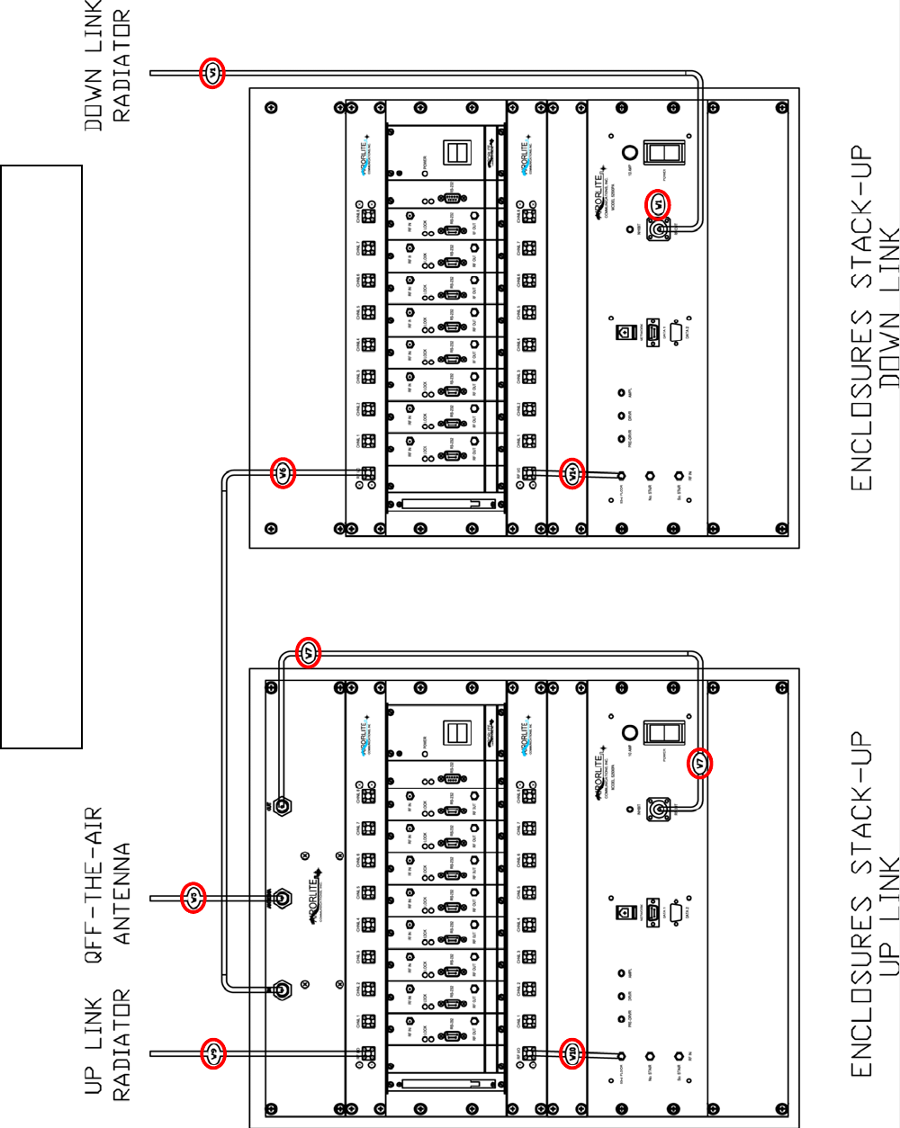
BASICCONNECTIONDIAGRAM
50289‐BA‐8‐PA
N:\netdrive\FCC\UserManual.doc
‐4‐
BASICCONNECTIONDIAGRAMKEY
IDItem1Item2
W1DownlinkPowerAmpOutputDownlinkRadiator
W5DuplexerAntennaPort"OfftheAir"Antenna
W6DuplexerDownlinkDownlink8WaySplitter
W7DuplexerUplinkUplinkPowerAmplifierOutput
W9Uplink8WaySplitterUplinkRadiator
W10Uplink8WayCombinerUplinkPowerAmplifierInput
W14Downlink8WayCombinerDownlinkPowerAmplifierInput
TheBasicConnectionDiagramshownabove,istheproperwaytheBDAshouldbeconnected
andonceupandrunning,requireminimaltononemanualconfiguration.Connectionsbetween
cabinetsaremadethroughN‐Bulkheadconnectorslocatedonthetopofeachcabinet.All
programmingandadjustingisdonethroughthesoftwareandthismanualprimarilydealswith
thistopic.
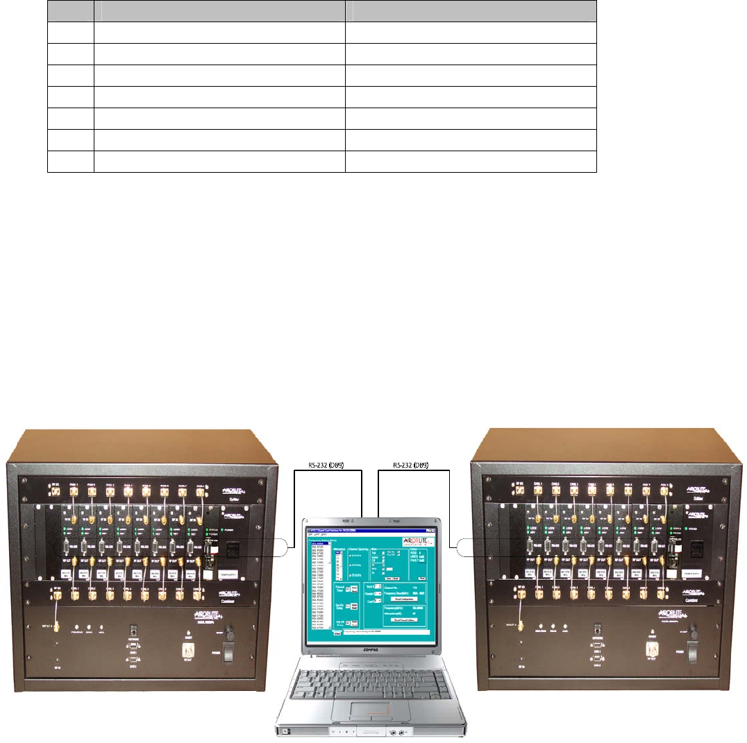
ThecomputerrunningthesoftwareisconnectedviaanRS232serialcabletoeachchannelcard
inthemannershownbelow.
50289‐BA‐8‐PA
N:\netdrive\FCC\UserManual.doc
‐5‐
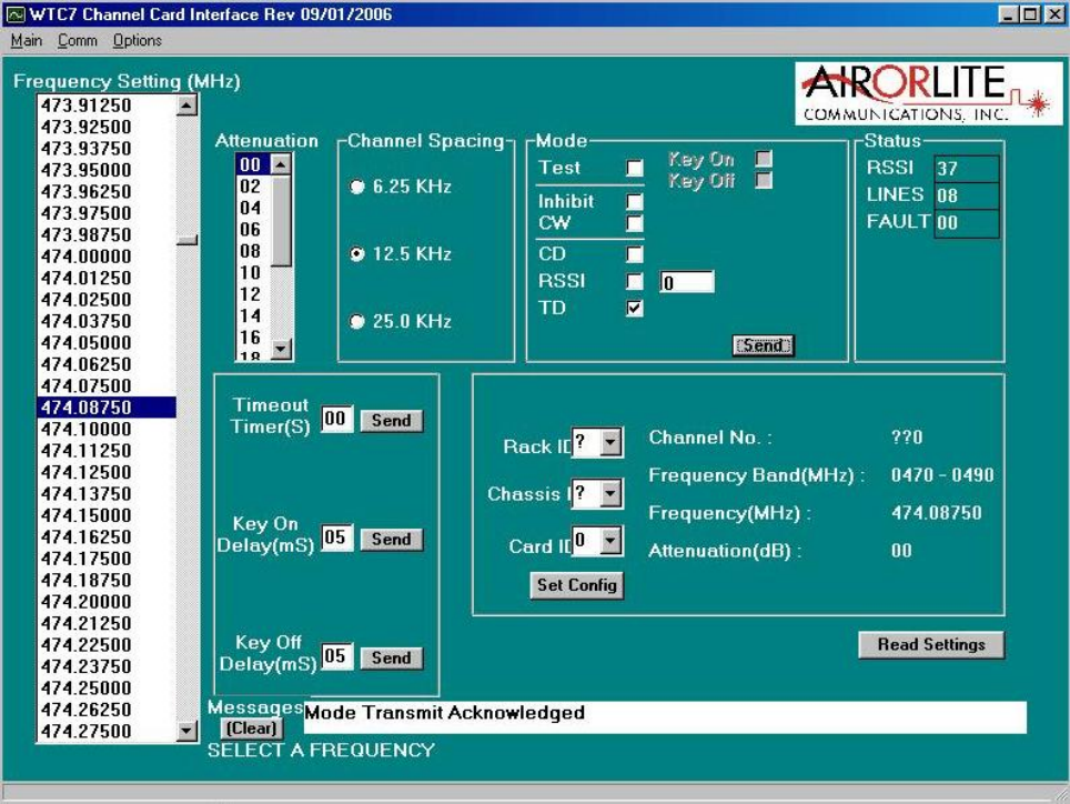
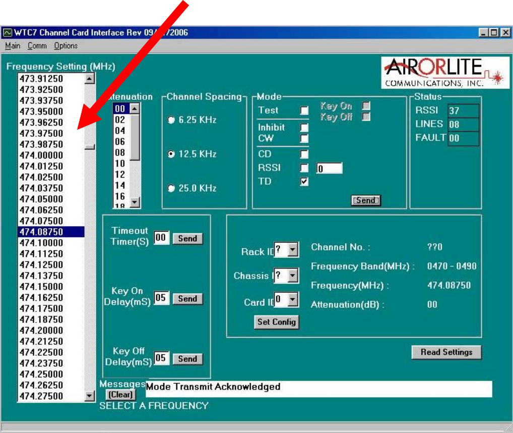
MAINSCREEN
Belowisthemainworkingscreenusedtoconfigurethechannelcardsettings.
Theprimaryfieldsaddressedare:
• CommunicationConnection
• TimeOutTimer
• ModeSetting
• KeyOnDelay
• KeyOffDelay
• Attenuation
• SettingaFrequency
50289‐BA‐8‐PA
N:\netdrive\FCC\UserManual.doc
‐6‐
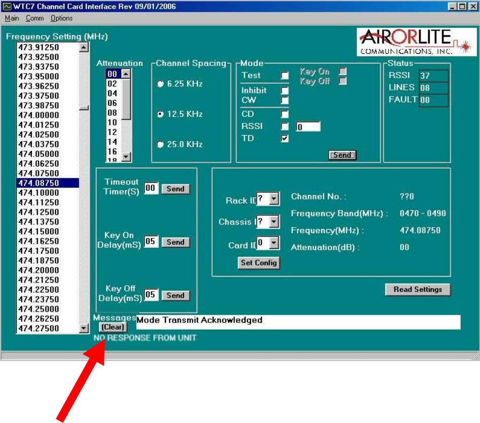
COMMUNICATIONCONNECTION
Thissoftwareautomaticallycheckstheconditionofitscommunicationwiththeintended
channel.Eachmessageisacknowledgedanddisplayedinthemessageboxatthebottomofthe
screen.Ifthesoftwaredoesnotreceivearesponsefromthechannel,awarningmessageis
displayed,“NORESPONSEFROMUNIT”.

50289‐BA‐8‐PA
N:\netdrive\FCC\UserManual.doc
‐7‐
TIMEOUTDURATION
Thetime‐outdurationishowlongachannelcanbeheldopen(keyedon)foraretransmission.
Aninadvertentorintentional“keyandhold”actionwithoutanyvoicecommunicationwillnot
disablethechannelbecauseofthisfeature.Thetime‐outdurationcanbeupsetfrom1second
to99seconds1secondintervals.Thetime‐outdurationcanbedisabledbysettingitto00,
whendisabled,thechannelwillkeycontinuouslywiththepresenceofareceivedsignal.
SETTINGATIME‐OUTTIME
Tosetatime‐outtime,clickonthetextbox“TimeOutTimer”andenterthedesiredtime‐out
timeupto99secondsthenclick“SendButton”nexttothebox.Toverifythesetting,clickon
the“ReadButton”andthedisplaywillbeupdatedwiththechannelsetting.
50289‐BA‐8‐PA
N:\netdrive\FCC\UserManual.doc
‐8‐
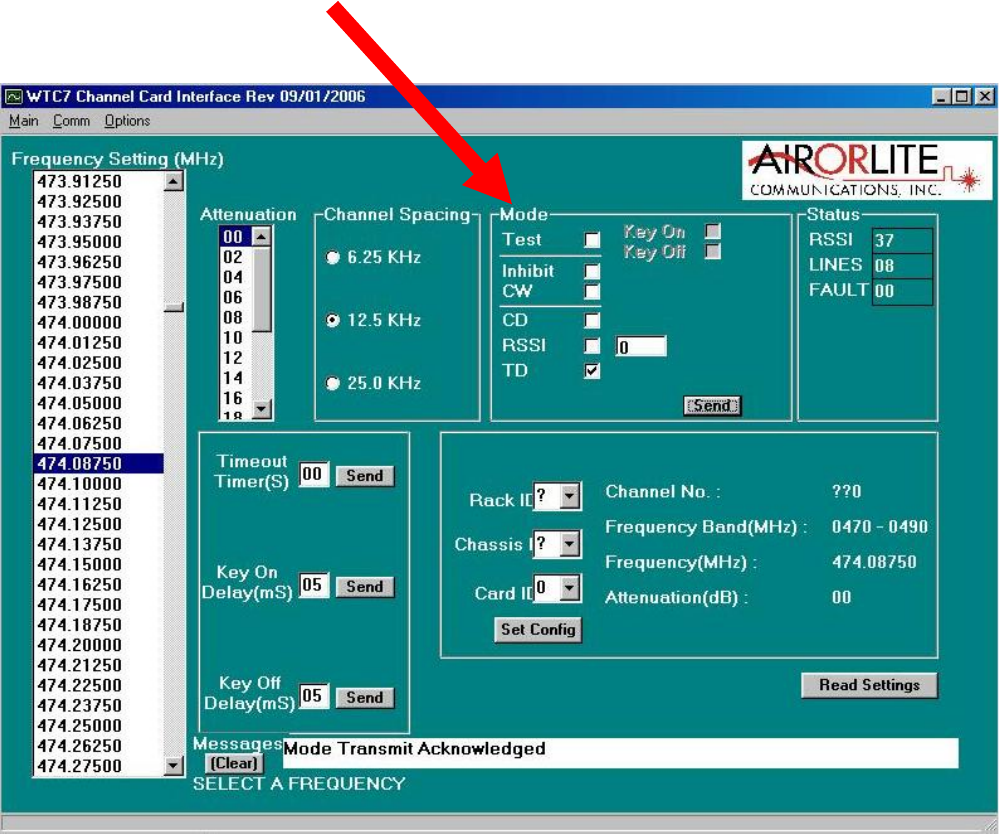
MODESETTING
ThechannelmodemaybesettoeitherINHIBIT,CONTINUOUS,CARRIERDETECToroptional
TONEDETECT.IntheInhibitmode,thechannelisoffandwillnotkeyon.Inthecontinuous
mode,CW,thechannelisalwayskeyedandcontinuouslytransmitting.Inthecarrierdetect
mode,CD,thechanneliskeyedonlywhentheincomingsignalstrengthisabovethefactoryset
thresholdlevel.NormaloperationwillbeinCDmode;continuousmodeisnormallyusedfor
testing.
CHANGINGTHEMODE
TochangetheMode,clickthedesiredfunctionboxonModeSelectiononthemainscreen.
Thenclick“SendButton”nexttothebox.Toverifythesetting,clickonthe“ReadButton”and
thedisplaywillbeupdatedwiththemodesetting.
50289‐BA‐8‐PA
N:\netdrive\FCC\UserManual.doc
‐9‐
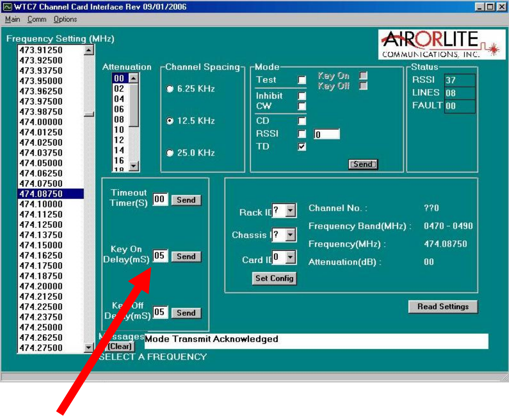
KEYONDELAY
Thekeyondelayisadelaydurationbetweenthedetectionofcarrierdetectandthe
transmitterkeyon.Thekeyondelaydurationcanbeupsetfrom0to99milliseconds1
millisecondintervals.
SETTINGKEYONDELAY
Tosetatime‐outtime,clickonthetextbox“KeyOnDelay”andenterthedesireddelayupto
99millisecondsthenclick“SendButton”nexttothebox.Toverifythesetting,clickonthe
“ReadButton”andthedisplaywillbeupdatedwiththechannelsetting.
50289‐BA‐8‐PA
N:\netdrive\FCC\UserManual.doc
‐10 ‐
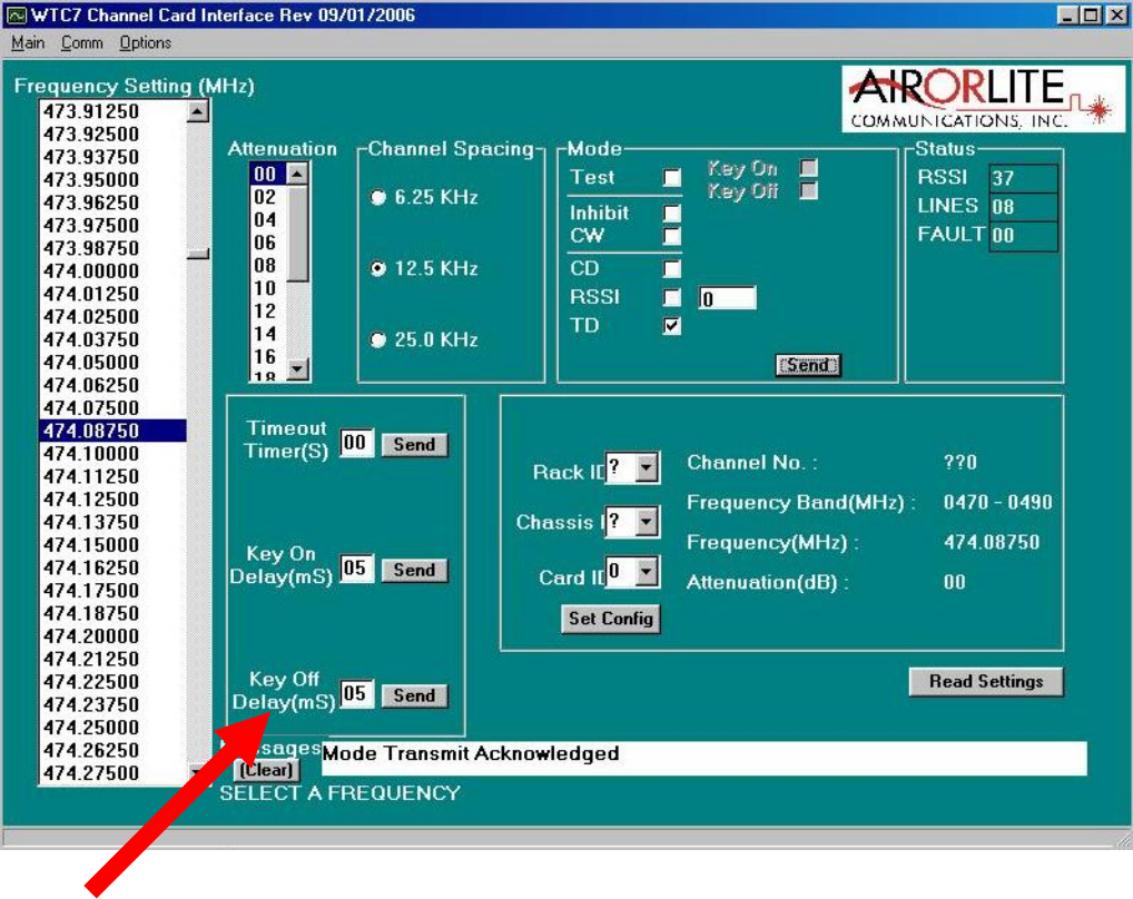
KEYOFFDELAY
Thekeyoffdelayisadelaydurationbetweenthereleaseofcarrierdetectandthetransmitter
keyoff.Thekeyoffdelaydurationcanbeupsetfrom0to99milliseconds1millisecond
intervals.
SETTINGKEYOFFDELAY
Tosetatime‐outtime,clickonthetextbox“KeyOffDelay”andenterthedesireddelayupto
99millisecondsthenclick“SendButton”nexttothebox.Toverifythesetting,clickonthe
“ReadButton”andthedisplaywillbeupdatedwiththechannelsetting.
50289‐BA‐8‐PA
N:\netdrive\FCC\UserManual.doc
‐11 ‐
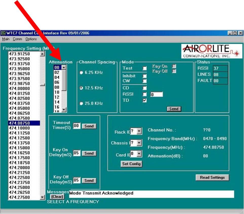
ATTENUATION
WithhighRFreceivelevels,aninputattenuatorcanbeset0to15dBin1dBsteps.
SETTINGATTENUATION
TosetAttenuation:clickthefunctionwindowAttenuationonthemainscreen.Clickonthe
scrollbarnexttothetextbox,ascrolldownlistofavailableattenuationsettings.DoubleClick
theondesiredsetting.
50289‐BA‐8‐PA
N:\netdrive\FCC\UserManual.doc
‐12 ‐
SETTINGAFREQUENCY
The8ChannelBDAisshippedwith8Uplinkfrequenciesand8Downlinkfrequencies.Theuser
canprogramanycardtoanyofthese8specifiedfrequencies.
TosetfrequencyclickthefunctionwindowFrequencySettingonthemainscreen.Clickonthe
scrollbarnexttothetextbox,ascrolldownlistofavailablefrequencysettings.DoubleClick
theondesiredsetting.
50289‐BA‐8‐PA
N:\netdrive\FCC\UserManual.doc
‐13 ‐
FCCCOMPLIANCEANDRFEXPOSUREINFORMATION
ThisproductiscertifiedbytheFCCascompliantwithCFR.47Part90.Anychangesor
modificationsnotexpresslyapprovedbythemanufacturercouldvoidtheuser’sauthorityto
operatetheequipment.
TocomplywithFCCRFexposurerequirements,antennasthataremountedexternallyat
remotelocationsoroperatingnearusersatstand‐alonedesktopofsimilarconfigurationsmust
operatewithaminimumseparationdistance,determinedatthetimeofsitelicensingfromall
persons.
ForDownlinkoperation,theminimumsafedistancefromtheantennais20cm.ForUplink
operation,theminimumsafedistancefromtheantennais60cm.
Note:ThisequipmenthasbeentestedandfoundtocomplywiththelimitsforaClassAdigital
device,pursuanttoPart15oftheFCCrules.Theselimitsaredesignedtoprovidereasonable
protectionagainstharmfulinterferenceinaresidentialinstallation.Thisequipmentgenerates,
uses,andcanradiateradiofrequencyenergy,ifnotinstalledandusedinaccordancewiththe
instructions,maycauseharmfulinterferencetoradiocommunications.Operationofthis
equipmentinaresidentialareaislikelytocauseharmfulinterferenceinwhichcasetheuserwill
berequiredtocorrecttheinterferenceatthisownexpense.