Airorlite Communications 50289BA8800UL Uplink Booster Amplifier User Manual

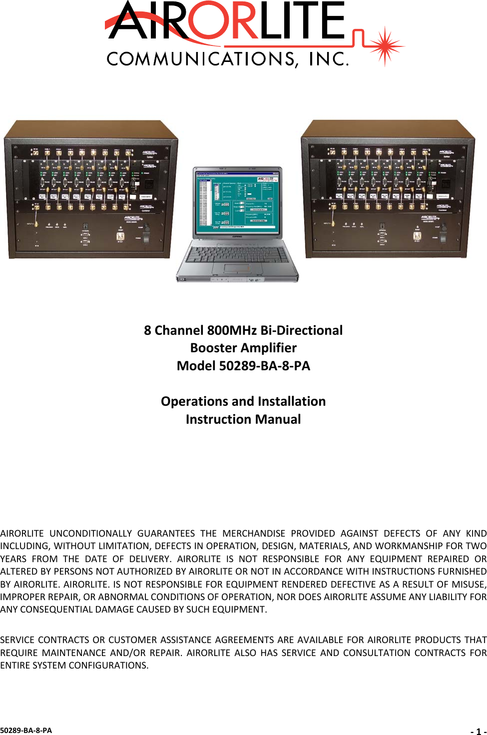
Airorlite Communications, Inc. Uplink Booster Amplifier

user manual

50289‐BA‐8‐PA‐1‐8Channel800MHzBi‐DirectionalBoosterAmplifierModel50289‐BA‐8‐PAOperationsandInstallationInstructionManualAIRORLITEUNCONDITIONALLYGUARANTEESTHEMERCHANDISEPROVIDEDAGAINSTDEFECTSOFANYKINDINCLUDING,WITHOUTLIMITATION,DEFECTSINOPERATION,DESIGN,MATERIALS,ANDWORKMANSHIPFORTWOYEARSFROMTHEDATEOFDELIVERY.AIRORLITEISNOTRESPONSIBLEFORANYEQUIPMENTREPAIREDORALTEREDBYPERSONSNOTAUTHORIZEDBYAIRORLITEORNOTINACCORDANCEWITHINSTRUCTIONSFURNISHEDBYAIRORLITE.AIRORLITE.ISNOTRESPONSIBLEFOREQUIPMENTRENDEREDDEFECTIVEASARESULTOFMISUSE,IMPROPERREPAIR,ORABNORMALCONDITIONSOFOPERATION,NORDOESAIRORLITEASSUMEANYLIABILITYFORANYCONSEQUENTIALDAMAGECAUSEDBYSUCHEQUIPMENT.SERVICECONTRACTSORCUSTOMERASSISTANCEAGREEMENTSAREAVAILABLEFORAIRORLITEPRODUCTSTHATREQUIREMAINTENANCEAND/ORREPAIR.AIRORLITEALSOHASSERVICEANDCONSULTATIONCONTRACTSFORENTIRESYSTEMCONFIGURATIONS.
50289‐BA‐8‐PA‐2‐SYSTEMSPECIFICATIONSDescriptionSPECIFICATIONSFrequencyRange 819‐824MHz&864‐869MHzOutboundSignal‐Uplink(#ofchannels=8)821.2150MHz 821.8125MHz(Uplinkchannelcardscanbeprogrammedtothesefrequenciesonly)822.3750MHz 822.8750MHz 823.0125MHz 823.5500MHz 823.6000MHz 823.9125MHzInboundSignal‐Downlink(#ofchannels=8)866.2125MHz 866.8125MHz(Downlinkchannelcardscanbeprogrammedtothesefrequenciesonly)867.3750MHz 867.8750MHz 868.0125MHz 868.5500MHz 868.6000MHz 868.9125MHzChannelBandwidth(Uplink/Downlink)25kHzNominalChannelSpacing25KHzRFFrequencyAccuracyTracksinputsignalexactlyAdjacentChannelSelectivity70dB@±17.5kHzFcRF Output Power (Downlink) ~25 dBm/carrier, minimum RF Output Power (Uplink) ~26 dBm/carrier, minimumVariationofOutputPowerw/InputLevel+0,‐1.0dBineitherdirectionMaximumPassbandRippleAcrossFullBand2dBMaximumPassbandRippleAcrossany100kHzsegment0.1dBAmplifierInputPorts(nodamage)0dBmPropagationDelay32microseconds,maximumIntermodulation/CrossmodulationDistortionatFullOutputPower‐60dBcChanneltoChannelIsolation‐70dBmMinimumHighBandSignaltoproduce+25dBmoutputtoRadiatingAntennaCable‐90dBmMinimumLowBandSignaltoproducefulloutput‐90dBmAGCControlRange(Uplink&Downlink)+80dBDutyCycleContinuousRFSpuriousOutput,lessthan800MHz,butgreaterthan1000MHz‐60dBc,MaximumRFSpuriousOutputforfrequenciesrangingfrom800‐1000MHz‐85dBc,MaximumOperatingTemperatureRange‐20°Cto+60°CSystemNoiseFigure<9dBInput/OutputImpedance50Ohms,nominalInput/OutputVSWR1.35:1,worstcaseInput/OutputConnectorsType“N”FemaleInputPower95‐132VAC,45‐64HzAmplifiersareunconditionallystable underalloperatingconditionsAlarmLossofPowerSupply,DCChangeincurrentdrawof+/‐20%foreachinternalamplifier
50289‐BA‐8‐PA‐3‐ConnectionChartBASICCONNECTIONDIAGRAM
50289‐BA‐8‐PA‐4‐BASICCONNECTIONDIAGRAMKEYIDItem1Item2W1DownlinkPowerAmpOutputDownlinkRadiatorW5DuplexerAntennaPort"OfftheAir"AntennaW6DuplexerDownlinkDownlink8WaySplitterW7DuplexerUplinkUplinkPowerAmplifierOutputW9Uplink8WaySplitterUplinkRadiatorW10Uplink8WayCombinerUplinkPowerAmplifierInputW14Downlink8WayCombinerDownlinkPowerAmplifierInputTheBasicConnectionDiagramshownabove,istheproperwaytheBDAshouldbeconnectedandonceupandrunning,requireminimaltononemanualconfiguration.ConnectionsbetweencabinetsaremadethroughN‐Bulkheadconnectorslocatedonthetopofeachcabinet.Allprogrammingandadjustingisdonethroughthesoftwareandthismanualprimarilydealswiththistopic.ThecomputerrunningthesoftwareisconnectedviaanRS232serialcabletoeachchannelcardinthemannershownbelow.
50289‐BA‐8‐PA‐5‐MAINSCREENBelowisthemainworkingscreenusedtoconfigurethechannelcardsettings.Theprimaryfieldsaddressedare:• CommunicationConnection• TimeOutTimer• ModeSetting• KeyOnDelay• KeyOffDelay• Attenuation• SettingaFrequency
50289‐BA‐8‐PA‐6‐COMMUNICATIONCONNECTIONThissoftwareautomaticallycheckstheconditionofitscommunicationwiththeintendedchannel.Eachmessageisacknowledgedanddisplayedinthemessageboxatthebottomofthescreen.Ifthesoftwaredoesnotreceivearesponsefromthechannel,awarningmessageisdisplayed,“NORESPONSEFROMUNIT”.
50289‐BA‐8‐PA‐7‐TIMEOUTDURATIONThetime‐outdurationishowlongachannelcanbeheldopen(keyedon)foraretransmission.Aninadvertentorintentional“keyandhold”actionwithoutanyvoicecommunicationwillnotdisablethechannelbecauseofthisfeature.Thetime‐outdurationcanbeupsetfrom1secondto99seconds1secondintervals.Thetime‐outdurationcanbedisabledbysettingitto00,whendisabled,thechannelwillkeycontinuouslywiththepresenceofareceivedsignal.SETTINGATIME‐OUTTIMETosetatime‐outtime,clickonthetextbox“TimeOutTimer”andenterthedesiredtime‐outtimeupto99secondsthenclick“SendButton”nexttothebox.Toverifythesetting,clickonthe“ReadButton”andthedisplaywillbeupdatedwiththechannelsetting.
50289‐BA‐8‐PA‐8‐MODESETTINGThechannelmodemaybesettoeitherINHIBIT,CONTINUOUS,CARRIERDETECToroptionalTONEDETECT.IntheInhibitmode,thechannelisoffandwillnotkeyon.Inthecontinuousmode,CW,thechannelisalwayskeyedandcontinuouslytransmitting.Inthecarrierdetectmode,CD,thechanneliskeyedonlywhentheincomingsignalstrengthisabovethefactorysetthresholdlevel.NormaloperationwillbeinCDmode;continuousmodeisnormallyusedfortesting.CHANGINGTHEMODETochangetheMode,clickthedesiredfunctionboxonModeSelectiononthemainscreen.Thenclick“SendButton”nexttothebox.Toverifythesetting,clickonthe“ReadButton”andthedisplaywillbeupdatedwiththemodesetting.
50289‐BA‐8‐PA‐9‐KEYONDELAYThekeyondelayisadelaydurationbetweenthedetectionofcarrierdetectandthetransmitterkeyon.Thekeyondelaydurationcanbeupsetfrom0to99milliseconds1millisecondintervals.SETTINGKEYONDELAYTosetatime‐outtime,clickonthetextbox“KeyOnDelay”andenterthedesireddelayupto99millisecondsthenclick“SendButton”nexttothebox.Toverifythesetting,clickonthe“ReadButton”andthedisplaywillbeupdatedwiththechannelsetting.
50289‐BA‐8‐PA‐10 ‐KEYOFFDELAYThekeyoffdelayisadelaydurationbetweenthereleaseofcarrierdetectandthetransmitterkeyoff.Thekeyoffdelaydurationcanbeupsetfrom0to99milliseconds1millisecondintervals.SETTINGKEYOFFDELAYTosetatime‐outtime,clickonthetextbox“KeyOffDelay”andenterthedesireddelayupto99millisecondsthenclick“SendButton”nexttothebox.Toverifythesetting,clickonthe“ReadButton”andthedisplaywillbeupdatedwiththechannelsetting.
50289‐BA‐8‐PA‐11 ‐ATTENUATIONWithhighRFreceivelevels,aninputattenuatorcanbeset0to15dBin1dBsteps.SETTINGATTENUATIONTosetAttenuation:clickthefunctionwindowAttenuationonthemainscreen.Clickonthescrollbarnexttothetextbox,ascrolldownlistofavailableattenuationsettings.DoubleClicktheondesiredsetting.
50289‐BA‐8‐PA‐12 ‐SETTINGAFREQUENCYThe8ChannelBDAisshippedwith8Uplinkfrequenciesand8Downlinkfrequencies.Theusercanprogramanycardtoanyofthese8specifiedfrequencies.TosetfrequencyclickthefunctionwindowFrequencySettingonthemainscreen.Clickonthescrollbarnexttothetextbox,ascrolldownlistofavailablefrequencysettings.DoubleClicktheondesiredsetting.
FCC Compliance and RF Exposure Information  This product is certified by the FCC as compliant with CFR.47 Part 90. Changes or modifications not expressly approved by the manufacturer could void the user's authority to operate the equipment.  To comply with FCC RF exposure requirements, antennas that are mounted externally at remote locations or operating near users at stand-alone desktop of similar configurations must operate with a minimum separation distance of 15 cm from all persons.  Note: This equipment has been tested and found to comply with the limits for a Class A digital device, pursuant to Part 15 of the FCC rules. These limits are designed to provide reasonable protection against harmful interference in a residential installation. This equipment generates, uses and can radiate radio frequency energy and, if not installed and used in accordance with the instructions, may cause harmful interference to radio communications. Operation of this equipment in a residential area is likely to cause harmful interference in which case the user will be required to correct the interference at his own expense.

Navigation menu