Airorlite Communications 50289BAM8800UL 8 Channel 800 MHz Bi-Directional Booster Amplifier User Manual Part 90

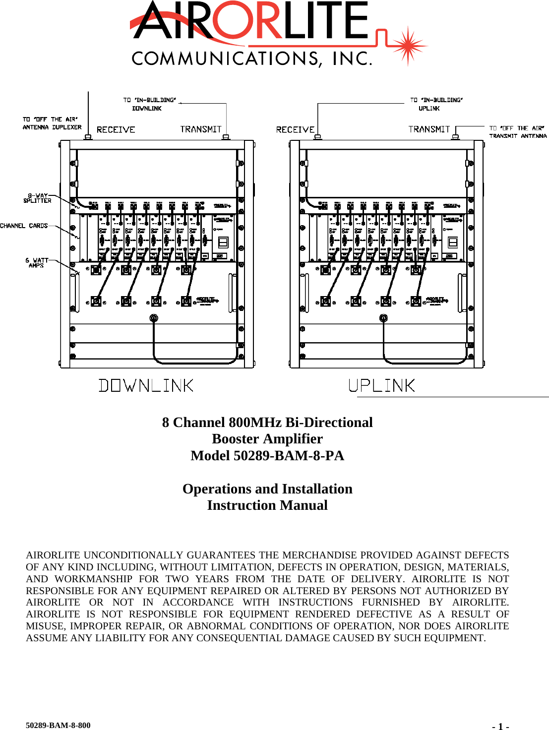
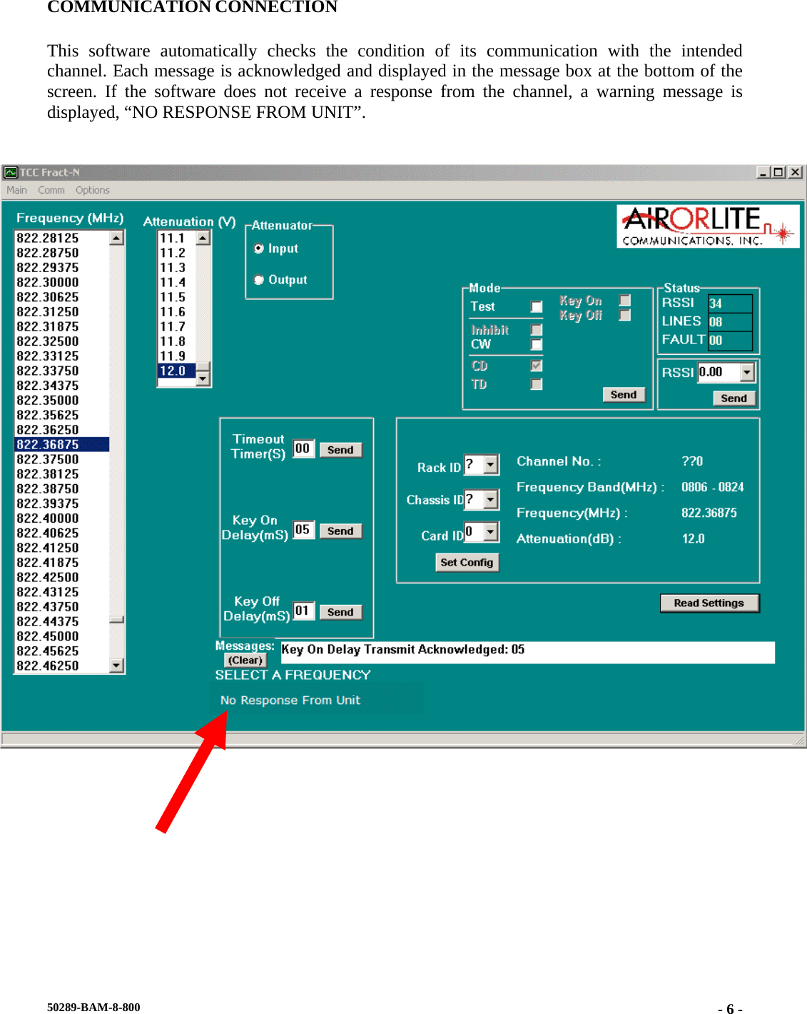
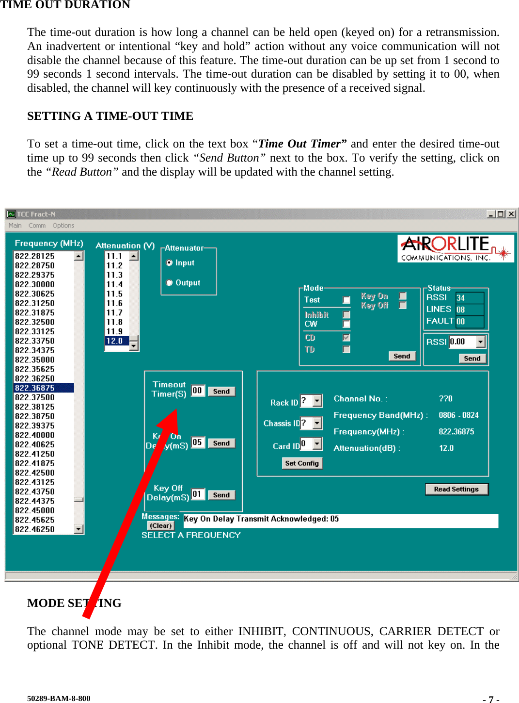
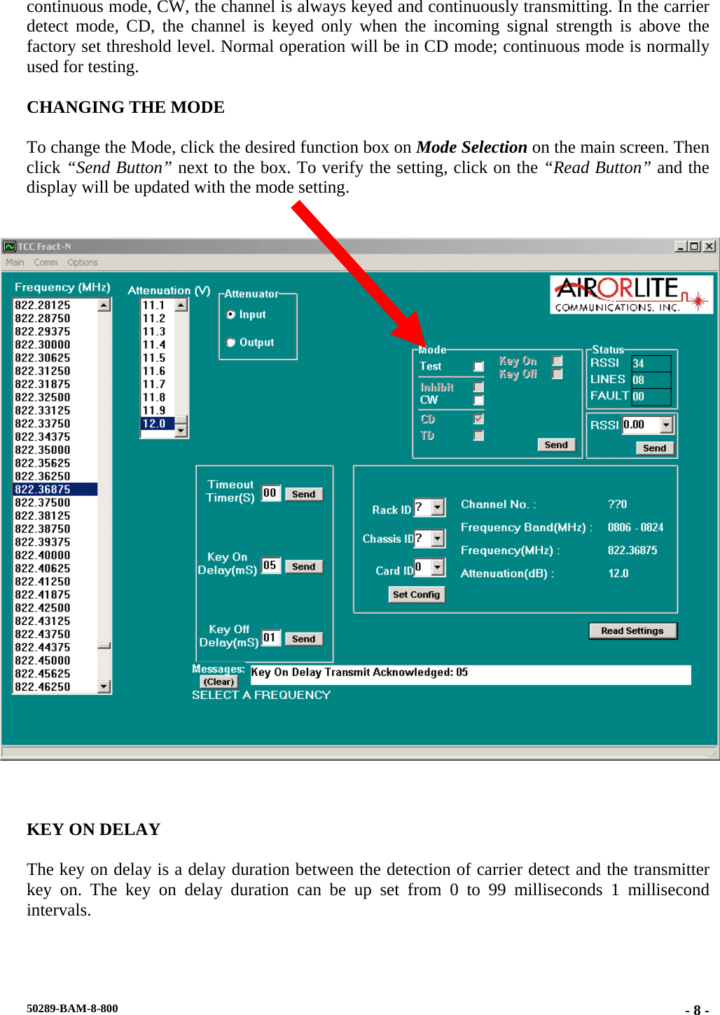
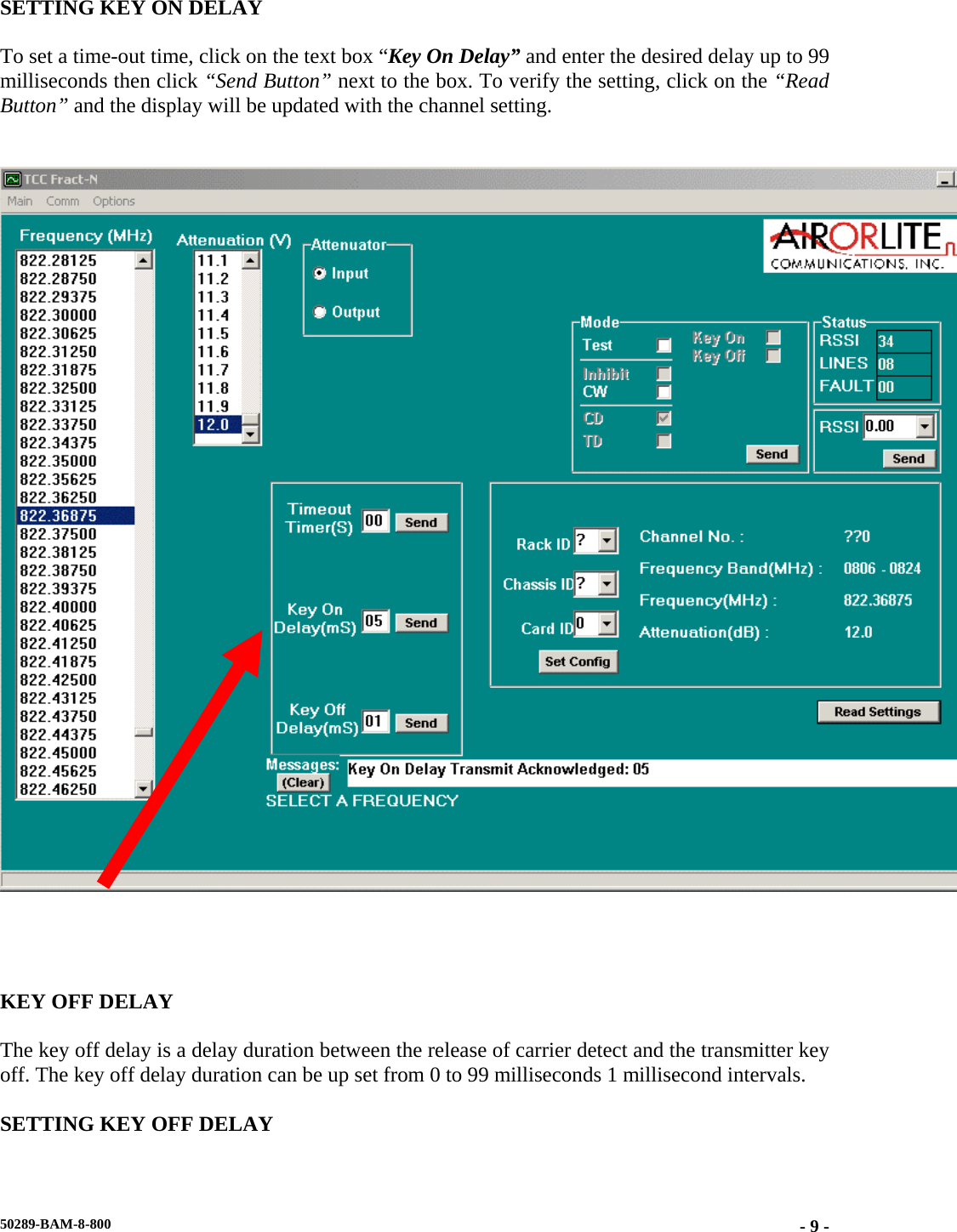
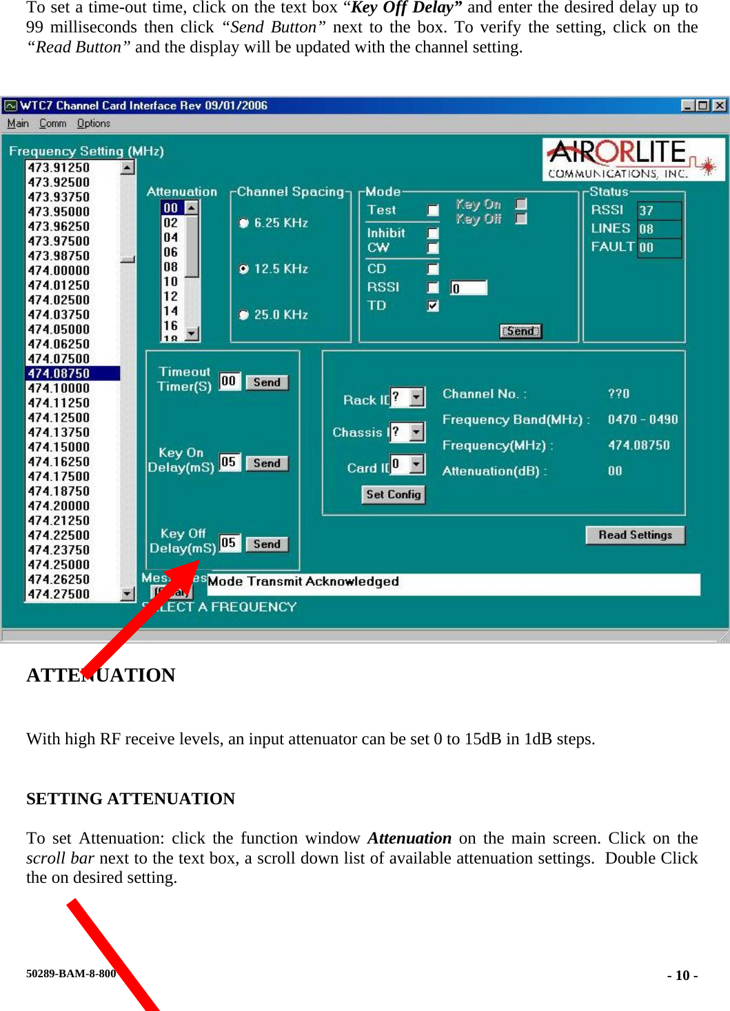
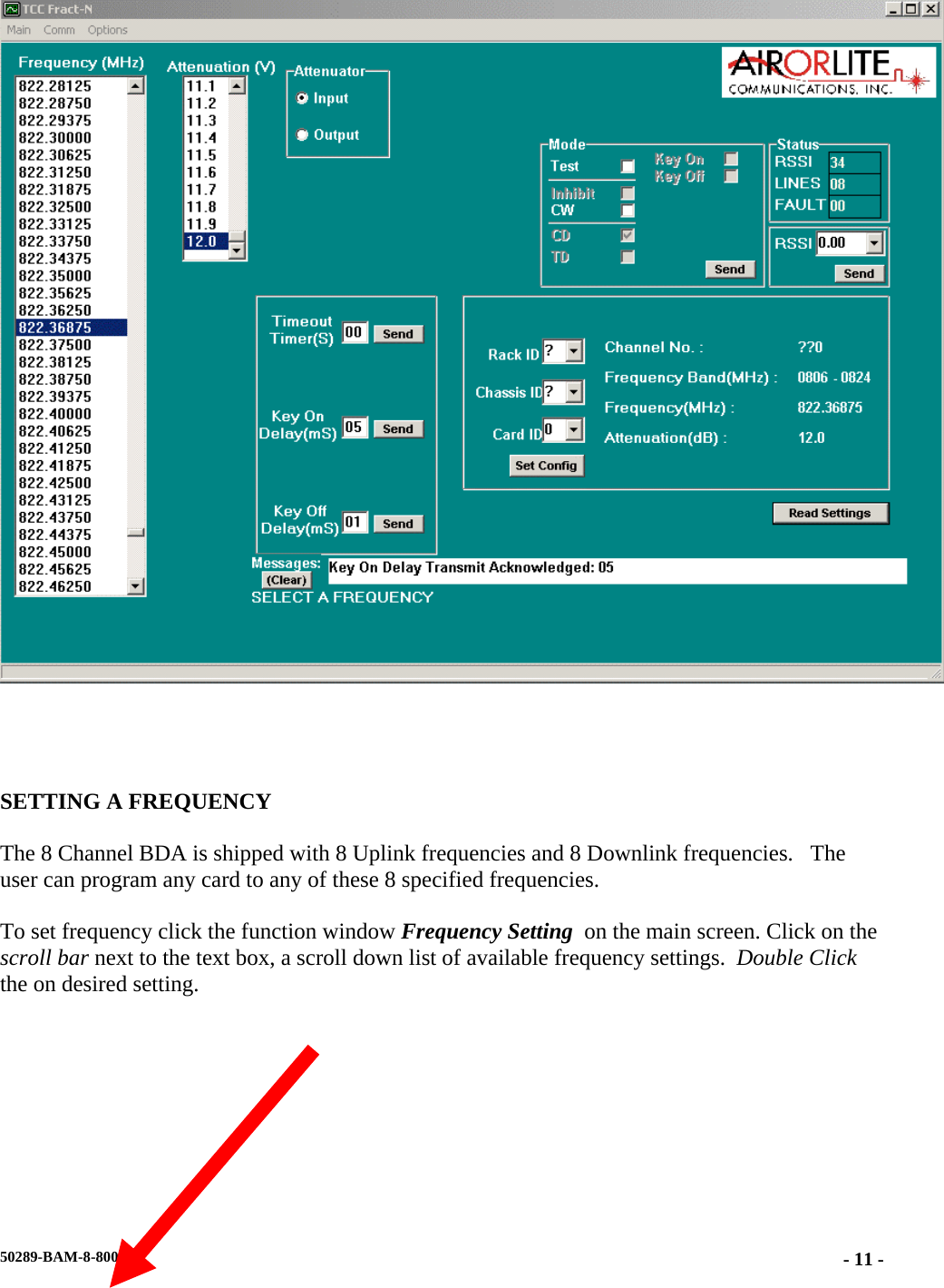
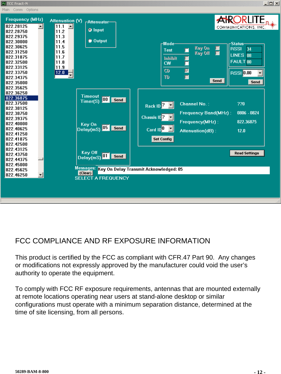
Airorlite Communications, Inc. 8 Channel 800 MHz Bi-Directional Booster Amplifier Part 90

User Manual

Rhein Tech Laboratories, Inc.  Client:  Airorlite Communications, Inc. 360 Herndon Parkway  Model:  50289-BAM-8-800-UL Suite 1400  Standards:  FCC Part 90 Herndon, VA 20170  FCC ID:  UT650289BAM8800UL http://www.rheintech.com Report Number:  2007314   36 of 40      Appendix J:  Manual   Please refer to the following pages for the manual.
       8 Channel 800MHz Bi-Directional  Booster Amplifier Model 50289-BAM-8-PA  Operations and Installation Instruction Manual    AIRORLITE UNCONDITIONALLY GUARANTEES THE MERCHANDISE PROVIDED AGAINST DEFECTS OF ANY KIND INCLUDING, WITHOUT LIMITATION, DEFECTS IN OPERATION, DESIGN, MATERIALS, AND WORKMANSHIP FOR TWO YEARS FROM THE DATE OF DELIVERY. AIRORLITE IS NOT RESPONSIBLE FOR ANY EQUIPMENT REPAIRED OR ALTERED BY PERSONS NOT AUTHORIZED BY AIRORLITE OR NOT IN ACCORDANCE WITH INSTRUCTIONS FURNISHED BY AIRORLITE. AIRORLITE IS NOT RESPONSIBLE FOR EQUIPMENT RENDERED DEFECTIVE AS A RESULT OF MISUSE, IMPROPER REPAIR, OR ABNORMAL CONDITIONS OF OPERATION, NOR DOES AIRORLITE ASSUME ANY LIABILITY FOR ANY CONSEQUENTIAL DAMAGE CAUSED BY SUCH EQUIPMENT.  50289-BAM-8-800  - 1 -
SERVICE CONTRACTS OR CUSTOMER ASSISTANCE AGREEMENTS ARE AVAILABLE FOR AIRORLITE PRODUCTS THAT REQUIRE MAINTENANCE AND/OR REPAIR. AIRORLITE ALSO HAS SERVICE AND CONSULTATION CONTRACTS FOR ENTIRE SYSTEM CONFIGURATIONS. 50289-BAM-8-800  - 2 -
 SYSTEM SPECIFICATIONS  Description  Specification Frequency Range  806-824 MHz,851-869 MHz Outbound Channels (Uplink)  8 max. in 806-824 MHz Band Inbound Channels (Downlink)  8 max. in 851-860 MHz Band Channel Bandwidth ( Uplink/Downlink)  > 100 kHz Channel Spacing  25 kHz RF Frequency Accuracy  Tracks input signal exactly Adjacent Channel Selectivity  70 dB @ ± 75 kHz Fc RF Output Power (Downlink)  +25 dBm per carrier RF Output Power (Uplink)  +26 dBm per carrier Variation of Output Power with Input Level  +0, -1.0 dB Maximum Passband Ripple across Full Band  2 dB Maximum Passband Ripple across any 100 kHz channel  1 dB Amplifier Input Ports (no damage)  -15 dBm Propagation Delay  <32 µs (typical) Intermodulation/Crossover Distortion at Full Output Power  -60 dBc all carriers present Channel to Channel Isolation  -70 dB Minimum Signal to produce Full Output Power  -90 dBm Dynamic Range   50 dB (typical) Duty Cycle  Continuous RF Spurious Output, < 800 MHz or > 1000 MHz  -60 dBc maximum RF Spurious Output 800 MHz- 1000 MHz  -85 dBc maximum System Noise Figure  < 9 dB (typical) Input/Output Impedance  50 Ohms Amplifier Damage (no damage)  Continuous short or open Input/Output VSWR  1.35:1 worst case Input/Output Connectors  Type N Female Operating Temperature Range  -20º C to + 60 º C  50289-BAM-8-800  - 3 -
 Basic Connections     The Basic Connection Diagram shown above, is the proper way the BDA should be connected and once up and running, require minimal to none manual configuration.  Connections between cabinets are made through N-Bulkhead connectors located on the top of each cabinet.  All programming and adjusting is done through the software and this manual primarily deals with this topic.  The computer running the software is connected via an RS232 serial cable to the front panel connector on each channel.   50289-BAM-8-800  - 4 -
MAIN SCREEN  Below is the main working screen used to configure the channel card settings.   The primary fields addressed are: • Communication Connection • Time Out Timer • Mode Setting • Key On Delay • Key Off Delay • Attenuation • Setting a Frequency       50289-BAM-8-800  - 5 -
 COMMUNICATION CONNECTION  This software automatically checks the condition of its communication with the intended channel. Each message is acknowledged and displayed in the message box at the bottom of the screen. If the software does not receive a response from the channel, a warning message is displayed, “NO RESPONSE FROM UNIT”.       Screen clipping taken: 1/15/2008, 12:02 PM     No Response Fro 50289-BAM-8-800  - 6 -
TIME OUT DURATION  The time-out duration is how long a channel can be held open (keyed on) for a retransmission. An inadvertent or intentional “key and hold” action without any voice communication will not disable the channel because of this feature. The time-out duration can be up set from 1 second to 99 seconds 1 second intervals. The time-out duration can be disabled by setting it to 00, when disabled, the channel will key continuously with the presence of a received signal.  SETTING A TIME-OUT TIME  To set a time-out time, click on the text box “Time Out Timer” and enter the desired time-out time up to 99 seconds then click “Send Button” next to the box. To verify the setting, click on the “Read Button” and the display will be updated with the channel setting.     MODE SETTING  The channel mode may be set to either INHIBIT, CONTINUOUS, CARRIER DETECT or optional TONE DETECT. In the Inhibit mode, the channel is off and will not key on. In the 50289-BAM-8-800  - 7 -
continuous mode, CW, the channel is always keyed and continuously transmitting. In the carrier detect mode, CD, the channel is keyed only when the incoming signal strength is above the factory set threshold level. Normal operation will be in CD mode; continuous mode is normally used for testing.  CHANGING THE MODE  To change the Mode, click the desired function box on Mode Selection on the main screen. Then click “Send Button” next to the box. To verify the setting, click on the “Read Button” and the display will be updated with the mode setting.        KEY ON DELAY  The key on delay is a delay duration between the detection of carrier detect and the transmitter key on. The key on delay duration can be up set from 0 to 99 milliseconds 1 millisecond intervals.  50289-BAM-8-800  - 8 -
SETTING KEY ON DELAY  To set a time-out time, click on the text box “Key On Delay” and enter the desired delay up to 99 milliseconds then click “Send Button” next to the box. To verify the setting, click on the “Read Button” and the display will be updated with the channel setting.       KEY OFF DELAY  The key off delay is a delay duration between the release of carrier detect and the transmitter key off. The key off delay duration can be up set from 0 to 99 milliseconds 1 millisecond intervals.  SETTING KEY OFF DELAY 50289-BAM-8-800  - 9 -
 To set a time-out time, click on the text box “Key Off Delay” and enter the desired delay up to 99 milliseconds then click “Send Button” next to the box. To verify the setting, click on the “Read Button” and the display will be updated with the channel setting.     ATTENUATION  With high RF receive levels, an input attenuator can be set 0 to 15dB in 1dB steps.   SETTING ATTENUATION  To set Attenuation: click the function window Attenuation on the main screen. Click on the scroll bar next to the text box, a scroll down list of available attenuation settings.  Double Click the on desired setting.  50289-BAM-8-800  - 10 -
       SETTING A FREQUENCY  The 8 Channel BDA is shipped with 8 Uplink frequencies and 8 Downlink frequencies.   The user can program any card to any of these 8 specified frequencies.  To set frequency click the function window Frequency Setting  on the main screen. Click on the scroll bar next to the text box, a scroll down list of available frequency settings.  Double Click the on desired setting.    50289-BAM-8-800  - 11 -
   FCC COMPLIANCE AND RF EXPOSURE INFORMATION This product is certified by the FCC as compliant with CFR.47 Part 90.  Any changes or modifications not expressly approved by the manufacturer could void the user’s authority to operate the equipment. To comply with FCC RF exposure requirements, antennas that are mounted externally at remote locations operating near users at stand-alone desktop or similar configurations must operate with a minimum separation distance, determined at the time of site licensing, from all persons.  50289-BAM-8-800  - 12 -
  For Downlink operation, the minimum safe distance from the antenna is 20cm with a maximum antenna gain of 0.6 dBi.  This specification is for operation in an uncontrolled environment. For Uplink operation, the minimum safe distance from the antenna is 40cm with a maximum antenna gain of 11 dBi.  This specification is for operation in a controlled environment. 50289-BAM-8-800  - 13 -

Navigation menu