Airorlite Communications 50289BAX8800DL Downlink Booster Amplifier User Manual
Airorlite Communications, Inc. Downlink Booster Amplifier Users Manual
Users Manual
50289‐BA‐8‐PA‐1‐
8Channel800MHzBi‐Directional
BoosterAmplifier
Model50289‐BA‐8‐PA
OperationsandInstallation
InstructionManual
AIRORLITEUNCONDITIONALLYGUARANTEESTHEMERCHANDISEPROVIDEDAGAINSTDEFECTSOFANYKIND
INCLUDING,WITHOUTLIMITATION,DEFECTSINOPERATION,DESIGN,MATERIALS,ANDWORKMANSHIPFORTWO
YEARSFROMTHEDATEOFDELIVERY.AIRORLITEISNOTRESPONSIBLEFORANYEQUIPMENTREPAIREDOR
ALTEREDBYPERSONSNOTAUTHORIZEDBYAIRORLITEORNOTINACCORDANCEWITHINSTRUCTIONSFURNISHED
BYAIRORLITE.AIRORLITE.ISNOTRESPONSIBLEFOREQUIPMENTRENDEREDDEFECTIVEASARESULTOFMISUSE,
IMPROPERREPAIR,ORABNORMALCONDITIONSOFOPERATION,NORDOESAIRORLITEASSUMEANYLIABILITYFOR
ANYCONSEQUENTIALDAMAGECAUSEDBYSUCHEQUIPMENT.
SERVICECONTRACTSORCUSTOMERASSISTANCEAGREEMENTSAREAVAILABLEFORAIRORLITEPRODUCTSTHAT
REQUIREMAINTENANCEAND/ORREPAIR.AIRORLITEALSOHASSERVICEANDCONSULTATIONCONTRACTSFOR
ENTIRESYSTEMCONFIGURATIONS.

50289‐BA‐8‐PA‐2‐
SYSTEMSPECIFICATIONS
DescriptionSPECIFICATIONS
FrequencyRange 819‐824MHz&864‐869MHz
OutboundSignal‐Uplink(#ofchannels=8)821.2150MHz
821.8125MHz
(Uplinkchannelcardscanbeprogrammedtothesefrequenciesonly)822.3750MHz
822.8750MHz
823.0125MHz
823.5500MHz
823.6000MHz
823.9125MHz
InboundSignal‐Downlink(#ofchannels=8)866.2125MHz
866.8125MHz
(Downlinkchannelcardscanbeprogrammedtothesefrequenciesonly)867.3750MHz
867.8750MHz
868.0125MHz
868.5500MHz
868.6000MHz
868.9125MHz
ChannelBandwidth(Uplink/Downlink)25kHzNominal
ChannelSpacing25KHz
RFFrequencyAccuracyTracksinputsignalexactly
AdjacentChannelSelectivity70dB@±17.5kHzFc
RF Output Power (Downlink) ~25 dBm/carrier, maximum
RF Output Power (Uplink) ~26 dBm/carrier, maximum
VariationofOutputPowerw/InputLevel+0,‐1.0dBineitherdirection
MaximumPassbandRippleAcrossFullBand2dB
MaximumPassbandRippleAcrossany100kHzsegment0.1dB
AmplifierInputPorts(nodamage)0dBm
PropagationDelay32microseconds,maximum
Intermodulation/CrossmodulationDistortionatFullOutputPower‐60dBc
ChanneltoChannelIsolation‐70dBm
MinimumHighBandSignaltoproduce+25dBmoutputtoRadiatingAntennaCable‐90dBm
MinimumLowBandSignaltoproducefulloutput‐90dBm
AGCControlRange(Uplink&Downlink)+80dB
DutyCycleContinuous
RFSpuriousOutput,lessthan800MHz,butgreaterthan1000MHz‐60dBc,Maximum
RFSpuriousOutputforfrequenciesrangingfrom800‐1000MHz‐85dBc,Maximum
OperatingTemperatureRange‐20°Cto+60°C
SystemNoiseFigure<9dB
Input/OutputImpedance50Ohms,nominal
Input/OutputVSWR1.35:1,worstcase
Input/OutputConnectorsType“N”Female
InputPower95‐132VAC,45‐64Hz
Amplifiersareunconditionallystable underalloperatingconditions
Alarm
LossofPowerSupply,DC
Changeincurrentdrawof+/‐20%for
eachinternalamplifier
50289‐BA‐8‐PA‐3‐
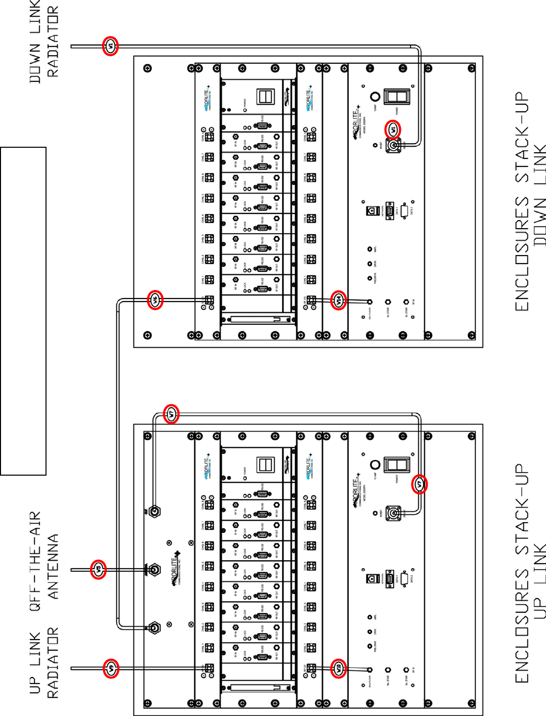
ConnectionChart
BASICCONNECTIONDIAGRAM
50289‐BA‐8‐PA‐4‐
BASICCONNECTIONDIAGRAMKEY
IDItem1Item2
W1DownlinkPowerAmpOutputDownlinkRadiator
W5DuplexerAntennaPort"OfftheAir"Antenna
W6DuplexerDownlinkDownlink8WaySplitter
W7DuplexerUplinkUplinkPowerAmplifierOutput
W9Uplink8WaySplitterUplinkRadiator
W10Uplink8WayCombinerUplinkPowerAmplifierInput
W14Downlink8WayCombinerDownlinkPowerAmplifierInput
TheBasicConnectionDiagramshownabove,istheproperwaytheBDAshouldbeconnected
andonceupandrunning,requireminimaltononemanualconfiguration.Connectionsbetween
cabinetsaremadethroughN‐Bulkheadconnectorslocatedonthetopofeachcabinet.All
programmingandadjustingisdonethroughthesoftwareandthismanualprimarilydealswith
thistopic.
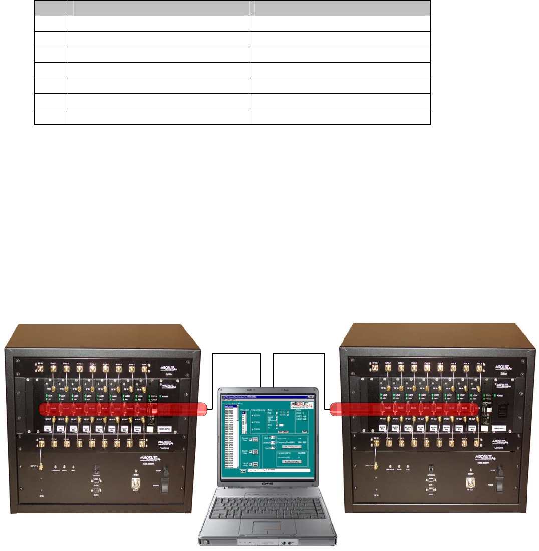
ThecomputerrunningthesoftwareisconnectedviaanRS232serialcabletoeachchannelcard
inthemannershownbelow.
50289‐BA‐8‐PA‐5‐
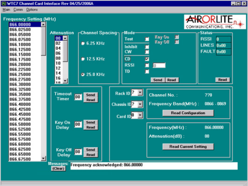
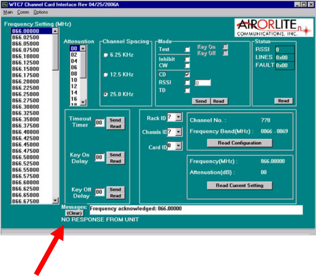
MAINSCREEN
Belowisthemainworkingscreenusedtoconfigurethechannelcardsettings.
Theprimaryfieldsaddressedare:
• CommunicationConnection
• TimeOutTimer
• ModeSetting
• KeyOnDelay
• KeyOffDelay
• Attenuation
• SettingaFrequency
50289‐BA‐8‐PA‐6‐
COMMUNICATIONCONNECTION
Thissoftwareautomaticallycheckstheconditionofitscommunicationwiththeintended
channel.Eachmessageisacknowledgedanddisplayedinthemessageboxatthebottomofthe
screen.Ifthesoftwaredoesnotreceivearesponsefromthechannel,awarningmessageis
displayed,“NORESPONSEFROMUNIT”.
50289‐BA‐8‐PA‐7‐
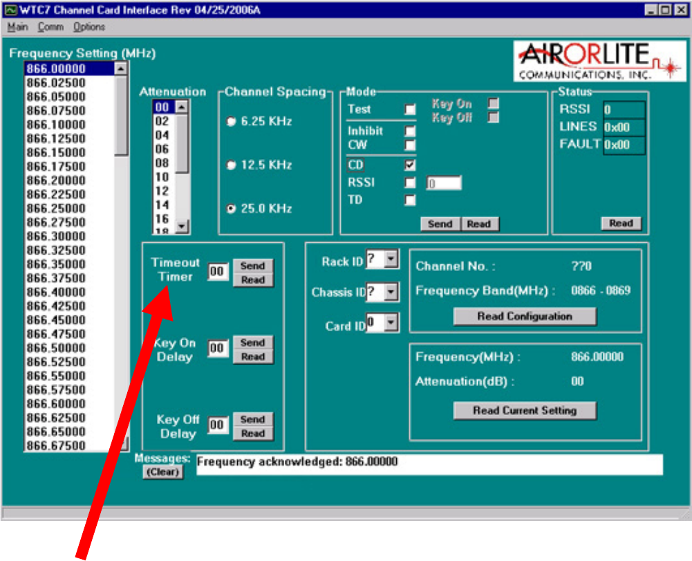
TIMEOUTDURATION
Thetime‐outdurationishowlongachannelcanbeheldopen(keyedon)foraretransmission.
Aninadvertentorintentional“keyandhold”actionwithoutanyvoicecommunicationwillnot
disablethechannelbecauseofthisfeature.Thetime‐outdurationcanbeupsetfrom1second
to99seconds1secondintervals.Thetime‐outdurationcanbedisabledbysettingitto00,
whendisabled,thechannelwillkeycontinuouslywiththepresenceofareceivedsignal.
SETTINGATIME‐OUTTIME
Tosetatime‐outtime,clickonthetextbox“TimeOutTimer”andenterthedesiredtime‐out
timeupto99secondsthenclick“SendButton”nexttothebox.Toverifythesetting,clickon
the“ReadButton”andthedisplaywillbeupdatedwiththechannelsetting.
50289‐BA‐8‐PA‐8‐
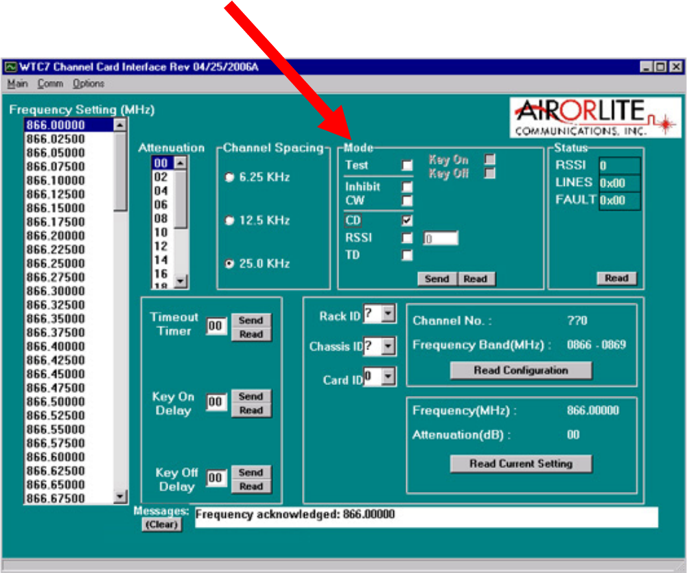
MODESETTING
ThechannelmodemaybesettoeitherINHIBIT,CONTINUOUS,CARRIERDETECToroptional
TONEDETECT.IntheInhibitmode,thechannelisoffandwillnotkeyon.Inthecontinuous
mode,CW,thechannelisalwayskeyedandcontinuouslytransmitting.Inthecarrierdetect
mode,CD,thechanneliskeyedonlywhentheincomingsignalstrengthisabovethefactoryset
thresholdlevel.NormaloperationwillbeinCDmode;continuousmodeisnormallyusedfor
testing.
CHANGINGTHEMODE
TochangetheMode,clickthedesiredfunctionboxonModeSelectiononthemainscreen.
Thenclick“SendButton”nexttothebox.Toverifythesetting,clickonthe“ReadButton”and
thedisplaywillbeupdatedwiththemodesetting.
50289‐BA‐8‐PA‐9‐
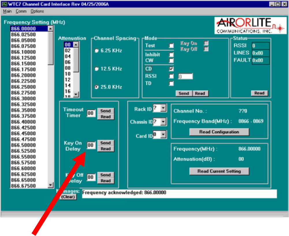
KEYONDELAY
Thekeyondelayisadelaydurationbetweenthedetectionofcarrierdetectandthe
transmitterkeyon.Thekeyondelaydurationcanbeupsetfrom0to99milliseconds1
millisecondintervals.
SETTINGKEYONDELAY
Tosetatime‐outtime,clickonthetextbox“KeyOnDelay”andenterthedesireddelayupto
99millisecondsthenclick“SendButton”nexttothebox.Toverifythesetting,clickonthe
“ReadButton”andthedisplaywillbeupdatedwiththechannelsetting.

50289‐BA‐8‐PA‐10 ‐
KEYOFFDELAY
Thekeyoffdelayisadelaydurationbetweenthereleaseofcarrierdetectandthetransmitter
keyoff.Thekeyoffdelaydurationcanbeupsetfrom0to99milliseconds1millisecond
intervals.
SETTINGKEYOFFDELAY
Tosetatime‐outtime,clickonthetextbox“KeyOffDelay”andenterthedesireddelayupto
99millisecondsthenclick“SendButton”nexttothebox.Toverifythesetting,clickonthe
“ReadButton”andthedisplaywillbeupdatedwiththechannelsetting.
50289‐BA‐8‐PA‐11 ‐
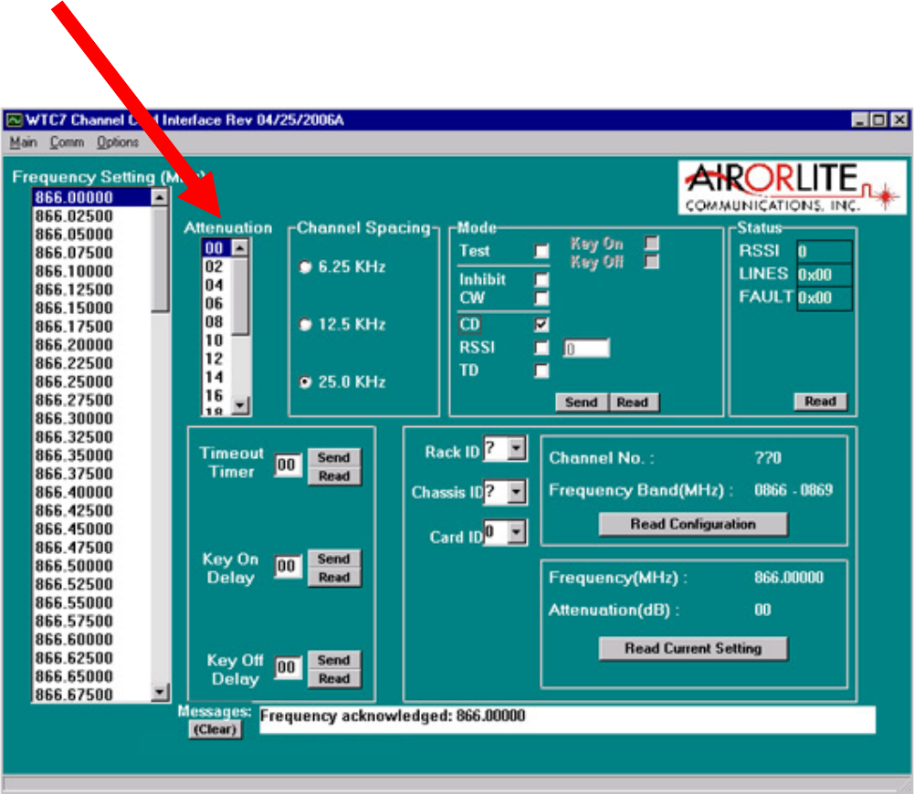
ATTENUATION
WithhighRFreceivelevels,aninputattenuatorcanbeset0to15dBin1dBsteps.
SETTINGATTENUATION
TosetAttenuation:clickthefunctionwindowAttenuationonthemainscreen.Clickonthe
scrollbarnexttothetextbox,ascrolldownlistofavailableattenuationsettings.DoubleClick
theondesiredsetting.
50289‐BA‐8‐PA‐12 ‐
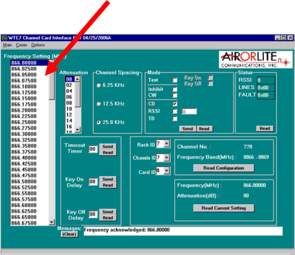
SETTINGAFREQUENCY
The8ChannelBDAisshippedwith8Uplinkfrequenciesand8Downlinkfrequencies.Theuser
canprogramanycardtoanyofthese8specifiedfrequencies.
TosetfrequencyclickthefunctionwindowFrequencySettingonthemainscreen.Clickonthe
scrollbarnexttothetextbox,ascrolldownlistofavailablefrequencysettings.DoubleClick
theondesiredsetting.
FCC Compliance and RF Exposure Information
This product is certified by the FCC as compliant with CFR.47 Part 90. Changes or
modifications not expressly approved by the manufacturer could void the user's authority
to operate the equipment.
To comply with FCC RF exposure requirements:
• In-building radiators must be installed to provide a separation distance of 20 cm
from personnel, consistent with limits provided for a mobile device.
• Roof-top antennas must be installed to provide a separation distance of 50cm
from personnel. (Note: designated limits assume a 2-meter separation distance,
the device is compliant at 50 cm.)
Note: This equipment has been tested and found to comply with the limits for a Class A
digital device, pursuant to Part 15 of the FCC rules. These limits are designed to provide
reasonable protection against harmful interference in a residential installation. This
equipment generates, uses and can radiate radio frequency energy and, if not installed and
used in accordance with the instructions, may cause harmful interference to radio
communications. Operation of this equipment in a residential area is likely to cause
harmful interference in which case the user will be required to correct the interference at
his own expense.