Airspan Communications 365AS Airsynergy WiMAX Basestation User Manual Installation guide
Airspan Communications Limited Airsynergy WiMAX Basestation Installation guide
Contents
- 1. Installation guide
- 2. User Manual statements for new band
Installation guide

SYN-UG-007 Rev 1
AirSynergy
Equipment
Installation Guide

AirSynergy Equipment Installation Guide
Page 2 Commercial in Confidence SYN-UG-007 Rev 1
Copyright
© Copyright by Airspan Networks Inc., 2011. All rights reserved worldwide.
The information contained within this document is proprietary and is subject to all relevant copyright,
patent and other laws protecting intellectual property, as well as any specific agreements protecting
Airspan Networks Inc. rights in the aforesaid information. Neither this document nor the information
contained herein may be published, reproduced or disclosed to third parties, in whole or in part,
without the express, prior, written permission of Airspan Networks Inc. In addition, any use of this
document or the information contained herein for the purposes other than those for which it is
disclosed is strictly forbidden.
Airspan Networks Inc. reserves the right, without prior notice or liability, to make changes in
equipment design or specifications.
Information supplied by Airspan Networks Inc. is believed to be accurate and reliable. However, no
responsibility is assumed by Airspan Networks Inc. for the use thereof nor for the rights of third parties
which may be effected in any way by the use of thereof.
Any representation(s) in this document concerning performance of Airspan Networks Inc. product(s)
are for informational purposes only and are not warranties of future performance, either expressed or
implied. Airspan Networks Inc. standard limited warranty, stated in its sales contract or order
confirmation form, is the only warranty offered by Airspan Networks Inc. in relation thereto.
This document may contain flaws, omissions or typesetting errors; no warranty is granted nor liability
assumed in relation thereto unless specifically undertaken in Airspan Networks Inc. sales contract or
order confirmation. Information contained herein is periodically updated and changes will be
incorporated into subsequent editions. If you have encountered an error, please notify Airspan
Networks Inc. All specifications are subject to change without prior notice.
Product performance figures quoted within this document are indicative and for information purposes
only.
UK WEE Registration number: WEE/AB0207WZ

AirSynergy Equipment Installation Guide
Page 3 Commercial in Confidence SYN-UG-007 Rev 1
Table of Contents
Copyright ................................................................................................................................................. 2
Table of Contents .................................................................................................................................... 3
Summary of Figures ................................................................................................................................ 5
Summary of Tables ................................................................................................................................. 6
1 About This Guide ............................................................................................................................ 7
1.1 Purpose ................................................................................................................................... 7
1.2 Intended Audience .................................................................................................................. 7
1.3 Conventions ............................................................................................................................ 7
1.4 Organisation of this Guide ....................................................................................................... 8
2 Introduction ...................................................................................................................................... 9
2.1 General Overview ................................................................................................................... 9
2.1.1 Sector Antenna arrangement .......................................................................................... 9
3 Get Started .................................................................................................................................... 10
3.1 Workflow of Installation ......................................................................................................... 10
3.2 Installation Checklist ............................................................................................................. 11
4 Verify Prerequisites ....................................................................................................................... 12
4.1 Verify Site Requirements ...................................................................................................... 12
4.2 Verify Safety Requirements .................................................................................................. 12
4.2.1 Warn of Hazardous Voltages ........................................................................................ 12
4.2.2 Adhere to European Directive 1999/519/EC ................................................................. 12
4.3 Verify Installation Requirements ........................................................................................... 13
4.3.1 Verify the Tools ............................................................................................................. 13
4.3.2 Verify the Parts and Kits ................................................................................................ 13
4.3.3 .............................................................................................................................................. 14
4.3.4 Verify Components ........................................................................................................ 15
5 Install the AirSynergy mounting plate .......................................................................................... 16
5.1 Mount the AirSynergy Universal Mounting Plate .................................................................. 16
6 Fit Front sector antenna to AirSynergy ........................................................................................ 18

AirSynergy Equipment Installation Guide
Page 4 Commercial in Confidence SYN-UG-007 Rev 1
6.1 Mount Front antenna to the AirSynergy unit ......................................................................... 18
6.2 Secure AirSynergy and Antenna to pole mount plate ........................................................... 20
6.3 Install GPS Antenna .............................................................................................................. 23
6.4 Install GPS antenna for AirSynergy ...................................................................................... 23
6.4.1 Mount the GPS Antenna ............................................................................................... 23
6.5 Connect PoE cable to the AirSynergy ................................................................................... 23
7 Connect to Power System ............................................................................................................. 24
7.1 Connect PSU Output to PoE injector .................................................................................... 24
7.2 Run cables from the PoE injector to the AirSynergy ............................................................. 24
8 Appendix A .................................................................................................................................... 25
8.1 Review Job Sheet ................................................................................................................. 25
9 Appendix C – Glossary of Terms .................................................................................................. 27
10 Appendix D – Checklist ............................................................................................................. 28
11 Appendix E ................................................................................................................................ 29
11.1 Revision History .................................................................................................................... 29

AirSynergy Equipment Installation Guide
Page 5 Commercial in Confidence SYN-UG-007 Rev 1
Summary of Figures
Figure 1 – Typical AirSynergy with sun shield mounted on street pole ................................................. 9
Figure 2 – Workflow of AirSynergy Installation ..................................................................................... 10
Figure 3 – AirSynergy connectorised unit with sunshield ..................................................................... 15
Figure 4 – AirSynergy unit with front sector antenna fitted ................................................................... 15
Figure 5 – AirSynergy mounting plate and fixings ............................................................................... 16
Figure 6 – Feed clamp bands through the quick release locking mechanisms .................................... 16
Figure 7 – AirSynergy mounting plate installed (large diameter concrete pole) ................................... 17
Figure 9 – AirSynergy front mount antenna and front mount plate ....................................................... 18
Figure 10 – Connecting the antenna RF cables .................................................................................. 18
Figure 11 – AirSynergy Front mount antenna connections – applying self amalgamating tape .......... 19
Figure 14 – Lift AirSynergy to top of pole-mount plate ........................................................................ 20
Figure 15 – AirSynergy downtilt adjustment ......................................................................................... 21
Figure 16 – Tighten flange nuts (4 poitions) once the required mounting angle is set ......................... 22
Figure 19 – AirSynergy attach earth cable to pole ............................................................................... 22
Figure 22 – AirSynergy power supply module and connection to the PoE injector .............................. 24

AirSynergy Equipment Installation Guide
Page 6 Commercial in Confidence SYN-UG-007 Rev 1
Summary of Tables
Table 1 - AirSynergy installation tools ................................................................................................... 13
Table 2 – AirSynergy installation parts and kits .................................................................................... 13
AirSynergy Equipment Installation Guide
Page 7 Commercial in Confidence SYN-UG-007 Rev 1
1 About This Guide
This section discusses the purpose, intended audience, conventions, referenced documentation and
organisation for this guide.
1.1 Purpose
This guide provides the workflow and step-by-step procedures for Installation of the AirSynergy
equipment. These procedures include:
Verify Prerequisites
Install the AirSynergy Radio equipment
Install the PSU equipment
Connect and manage cables
1.2 Intended Audience
This guide is intended for persons who are responsible for installing the AirSynergy equipment.
These persons should have a working knowledge of the equipment.
1.3 Conventions
This document uses the following informational conventions.
Icon
Description
Checkpoint: Marks a point in the workflow where there may be an exit or branch
to some other procedure. At each Checkpoint the reason for an exit or branch is
given along with specific directions to locate the entry point in the other
procedure.
Reference: Gives a resource in the workflow that may be needed to complete a
procedure along with specific directions to use the resource.
Caution: Describes a possible risk and how to lessen or avoid the risk.
Advice: Provides a recommendation based on best practice.
Note: Provides useful information.

AirSynergy Equipment Installation Guide
Page 8 Commercial in Confidence SYN-UG-007 Rev 1
1.4 Organisation of this Guide
This guide is organised into the following Sections:
About this Guide
Introduction
Get Started
Verify Prerequisites
Install the AirSynergy Radio equipment
Install the PSU equipment
Connect and manage cables
Appendixes
AirSynergy Equipment Installation Guide
Page 9 Commercial in Confidence SYN-UG-007 Rev 1
2 Introduction
This section provides a descriptive overview of the product.
2.1 General Overview
AirSynergy equipment comes in a range of frequency variants that can be mounted with different
antenna options
Figure 1 – Typical AirSynergy with sun shield mounted on street pole
2.1.1 Sector Antenna arrangement
A typical sector installation will have a cross- polar sector antenna fitted directly to the front of the
AirSynergy main unit. (This is fitted instead of the sun-shield).
Figure 2 – AirSynergy with front sector antenna fitted
AirSynergy Equipment Installation Guide
Page 10 Commercial in Confidence SYN-UG-007 Rev 1
3 Get Started
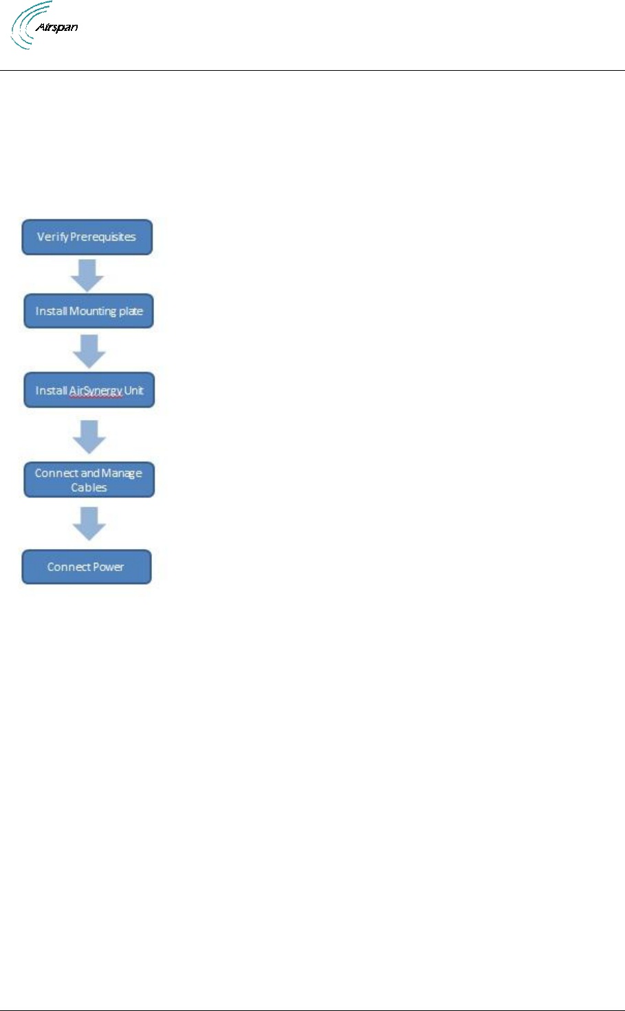
3.1 Workflow of Installation
The workflow required to install the AirSynergy equipment is shown in the following diagram:
Figure 2 – Workflow of AirSynergy Installation

AirSynergy Equipment Installation Guide
Page 11 Commercial in Confidence SYN-UG-007 Rev 1
3.2 Installation Checklist
Plan the installation of the AirSynergy Unit by using the Installation Checklist in Appendix A.
AirSynergy Equipment Installation Guide
Page 12 Commercial in Confidence SYN-UG-007 Rev 1
4 Verify Prerequisites
4.1 Verify Site Requirements
To set up the AirSynergy for connection to Netspan, a PC will be required.
4.2 Verify Safety Requirements
Read and follow all warning notices and instructions marked on the product or included in this
manual.
When installed in the final configuration, the product must comply with the applicable Safety
Standards and regulatory requirements of the country in which it is installed. If necessary, consult with
the appropriate regulatory agencies and inspection authorities to ensure compliance.
Ascertain the radiation hazards when working in an environment close to other antennas and
Electromagnetic fields, e.g. working on towers with other microwave transmitters etc. and act
accordingly.
4.2.1 Warn of Hazardous Voltages
On AC installations, hazardous voltages exist. Use caution when verifying or working with AC power.
Remove metal jewellery that could come into contact with AC power.
On DC sections, short circuiting the low voltage, low impedance circuits can cause arcing that may
result in burns or eye damage. Remove rings, watches etc. to avoid shorting DC circuits.
Note: Airspan products do not contain hazardous substances (as defined in UK
Control of Substances Hazardous to Health Regulations 1989 and the Dangerous
Substances Regulations 1990). At the end of any Airspan products life cycle, the
customer should consult with Airspan to ensure that the product is disposed of in
conformance with the relevant regulatory requirements.
Caution: Any modifications to this device not expressly authorised by the
manufacturer could void the users’ authority to operate this device.
4.2.2 Adhere to European Directive 1999/519/EC
European Directive 1999/519/EC details basic restrictions and reference levels on human exposure to
electromagnetic fields as advised by the ICNIRP. The directive states that adherence to these
recommended restrictions and reference levels should provide a high level of protection as regards
the established health effects that may result from exposure to such fields.
AirSynergy Equipment Installation Guide
Page 13 Commercial in Confidence SYN-UG-007 Rev 1
4.3 Verify Installation Requirements
4.3.1 Verify the Tools
Table 1 - AirSynergy installation tools
Tools
Small flat blade Screwdriver
Large Flat Bladed Screwdriver
20mm wrench or small Pipe wrench
10mm wrench
Wire strippers
Wire cutters
Small cross-head screwdriver
Ring terminals crimp tool
Tilt-meter (if accurate downtilt needs to be set)
Krone punch-down tool
4.3.2 Verify the Parts and Kits
Table 2 – AirSynergy installation parts and kits
Installation Kit /
Part:
Installation Kit details
Note:
AirSynergy
mounting
1 x AirSynergy Universal
Mounting Plate
1 x Sun Shield
1 x Sector Antenna mounting
plate with fixing kit
4 M4 nuts
4 M4 flat washers
4 M4 spring washers
4 M5 SEMs
1 x Sector Antenna (front
mounting)
AirSynergy Equipment Installation Guide
Page 14 Commercial in Confidence SYN-UG-007 Rev 1
Table 3 - AirSynergy additional items
Additional items (not provided by Airspan)
Cable ties
Self amalgamating tape
Black PVC tape
Ring terminal for earth strap, M6
Earth strap cable (4mm), yellow and green cable
Table 4 – Antenna and feeder kits
Installation Kit / Part
Note
Antenna / Feeder (not
always provided by
Airspan)
Antenna and feeder
Short feeder tail length of 0.5
to 1.5m x2
Table 5 - AirSynergy additional items
Additional items (not provided by Airspan)
Cable ties
Self-amalgamating tape
Black PVC tape
Ring terminal for earth strap, M6
Earth strap cable (4mm), yellow and green cable
4.3.3
Connecting
cables
CAT5e
External grade 25m with Weather
hood pre-fitted
Earthing cable
M6 Lug at each end
AirSynergy Equipment Installation Guide
Page 15 Commercial in Confidence SYN-UG-007 Rev 1
4.3.4 Verify Components
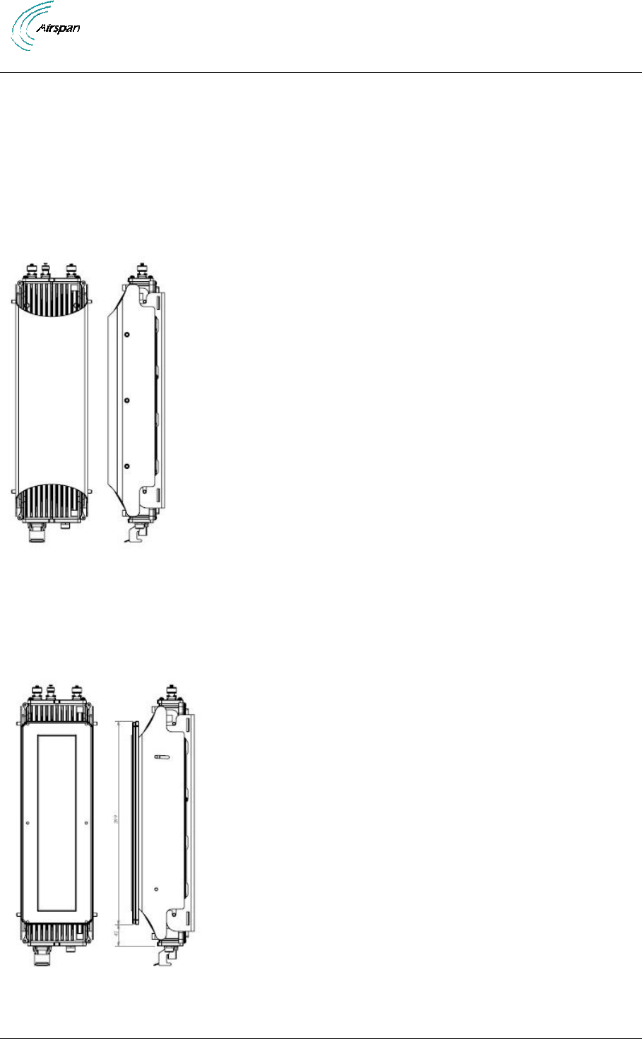
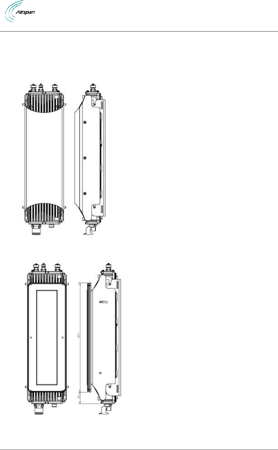
AirSynergy
AirSynergy connectorised unit
Figure 3 – AirSynergy connectorised unit with sunshield
Figure 4 – AirSynergy unit with front sector antenna fitted
AirSynergy Equipment Installation Guide
Page 16 Commercial in Confidence SYN-UG-007 Rev 1
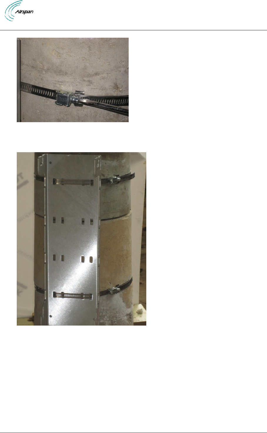
5 Install the AirSynergy mounting plate
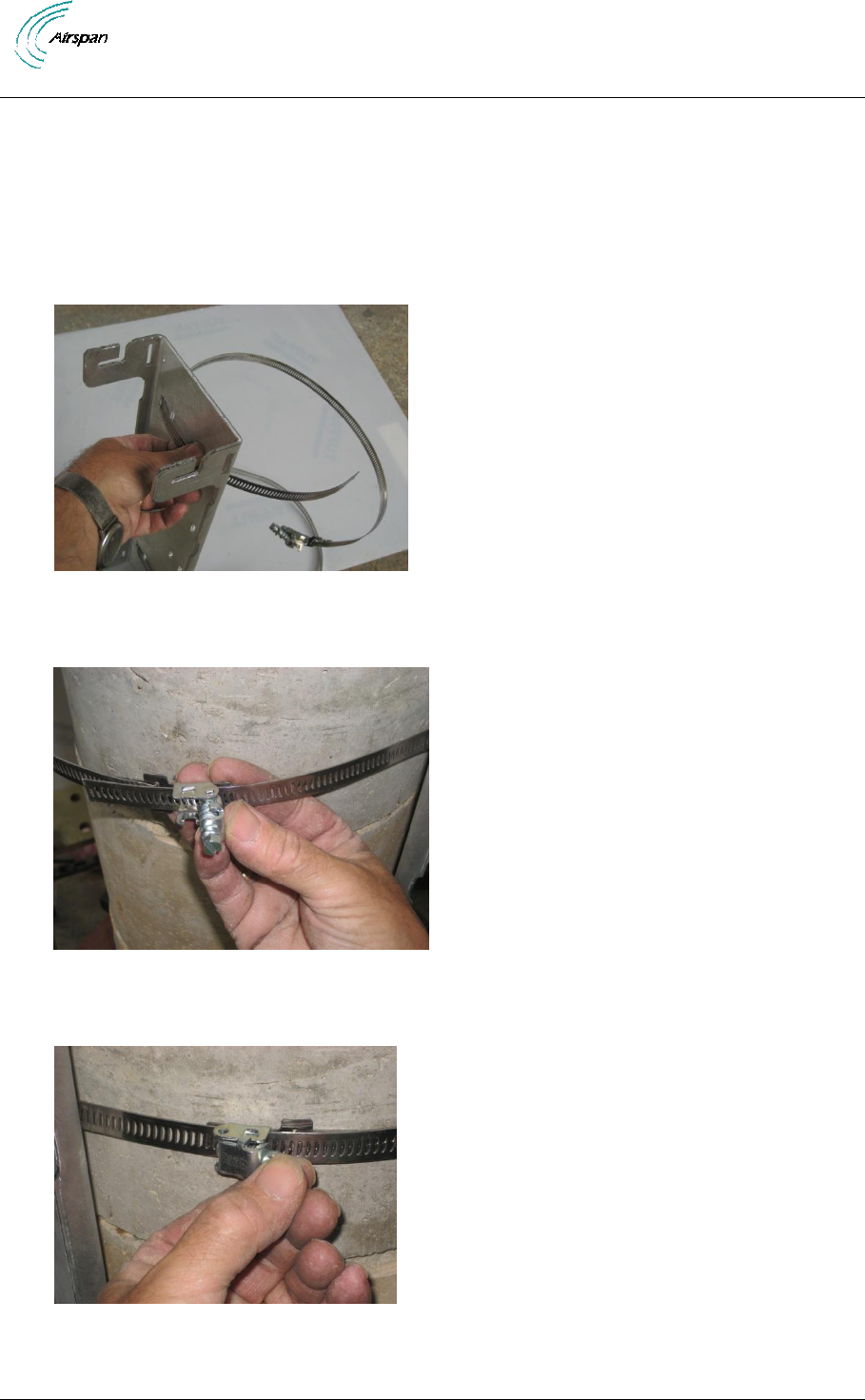
5.1 Mount the AirSynergy Universal Mounting Plate
The AirSynergy is normally mounted on a pole (in close proximity to its external antenna if not using
the AirSynergy front mounted Antenna. Take care to install the mounting plate the correct way up so
that the AirSynergy unit will fit with the PoE connector pointing downwards.
Figure 5 – AirSynergy mounting plate and fixings
Figure 6 – Feed clamp bands through the quick release locking mechanisms
Figure 7 – Press down the locking mechanism with the slack band fed through
AirSynergy Equipment Installation Guide
Page 17 Commercial in Confidence SYN-UG-007 Rev 1
Figure 8 – Tighten clamps with large flat blade screwdriver
Figure 7 – AirSynergy mounting plate installed (large diameter concrete pole)
AirSynergy Equipment Installation Guide
Page 18 Commercial in Confidence SYN-UG-007 Rev 1
6 Fit Front sector antenna to AirSynergy
The AirSynergy unit can be used either with a sector antenna mounted directly on the front or with a
remotely attached RF antenna.
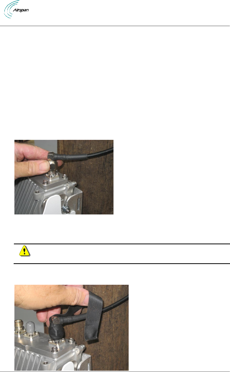
6.1 Mount Front antenna to the AirSynergy unit
To mount the front antenna , perform the following steps:
Add text here to describe the mounting of the antenna to the front mount plate, securing of the
antenna cables with cable ties and the fitting of the antenna plus front mount plate to the front of the
AirSynergy unit.
Figure 8 – AirSynergy front mount antenna and front mount plate
Figure 9 – Connecting the antenna RF cables
Caution: Do not over-tighten the RF connector. RF failures can result when the
RF connector is over-tightened.
Weather-proofing of the RF N type connectors with weather-proofing tapes. (self amalgamating
followed by a layer of balck PVC tape.
AirSynergy Equipment Installation Guide
Page 19 Commercial in Confidence SYN-UG-007 Rev 1
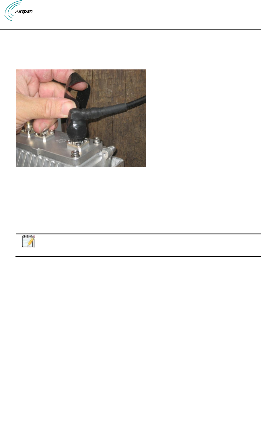
Figure 10 – AirSynergy Front mount antenna connections – applying self amalgamating tape
Apply a layer of self amalgamating tape and a layer of electrical tape to the weather-exposed RF
connector.
Figure 12 – AirSynergy antenna connections – applying PVC tape
Ensure the RF connector is completely sealed from the weather.
Figure 13 – AirSynergy antenna with sealed RF connections
Note: It is recommended to place some cardboard or paper under the unit to
protect it from scratching.

AirSynergy Equipment Installation Guide
Page 20 Commercial in Confidence SYN-UG-007 Rev 1
6.2 Secure AirSynergy and Antenna to pole mount plate
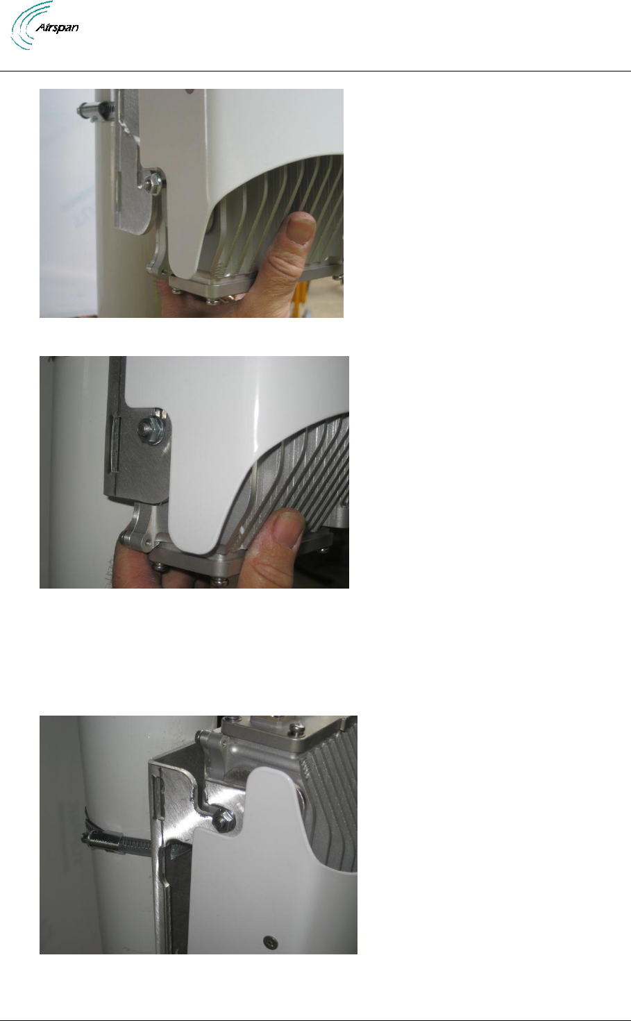
To mount the AirSynergy to the universal mounting plate, perform the following steps:
1. Hook the studs into the top slots of the mounting plate. With the studs engaged in the top
slots raise the unit slightly until the bottom studs also drop into their respective slots. Secure
the flange nuts (4 positions).
Figure 11 – Lift AirSynergy to top of pole-mount plate
Figure 5 – AirSynergy drops down into slots at the top of pole-mount plate
AirSynergy Equipment Installation Guide
Page 21 Commercial in Confidence SYN-UG-007 Rev 1
Figure 16 – Gently lift the AirSynergy body until the bottom studs engage in the bottom slots
Figure 17 – AirSynergy body engaged in the bottom slots
2. The slot arrangement at the top allow the AirSynergy and front mounted antenna to be down-
tilted by a few degrees to provide real downtilt or to compensate for the taper angle on the
pole. With the flange nuts gently hand tightened the position can be accurately set with tilt-
meter on the front face of the AirSynergy unit.
Figure 12 – AirSynergy downtilt adjustment
AirSynergy Equipment Installation Guide
Page 22 Commercial in Confidence SYN-UG-007 Rev 1
3. The downtilt angles are not marked by the adjustment slots so a tiltmeter is required to set a
specific angle and then tighten the flange nuts ith a 10mm wrench on each stud (4 positions)
Figure 13 – Tighten flange nuts (4 poitions) once the required mounting angle is set
4. There is an option to connect an earthing cable to the M6 screw fixing point at the bottom of
the main body casting. This should be connected to a protection ground bar or directly to the
steel structure of the power or pole. This is only required in areas of high lightning activity or
when the AirSynergy unit is mounted on high exposed roofs or tower structures
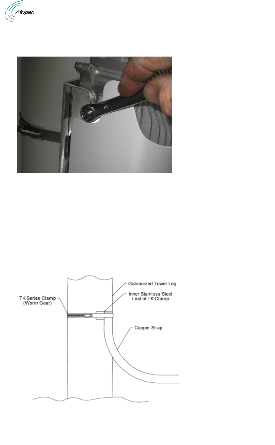
5. Connect the earth cable to the protection earth bar using suitable crimp lugs. Alternatively
use a TK series clamp to join the earth cable to the steel structure of the mounting pole or
tower structure.
Figure 14 – AirSynergy attach earth cable to pole

AirSynergy Equipment Installation Guide
Page 23 Commercial in Confidence SYN-UG-007 Rev 1
.
6.3 Install GPS Antenna
6.4 Install GPS antenna for AirSynergy
Note: AirSynergy units without a factory fitted Switching antenna all require a
GPS antenna which comes in a kit with a mounting bracket and a 25cm cable. A
prime consideration for a GPS antenna is a clear view of the sky, preferably 360
degrees
Install the GPS antenna bracket to the AirSynergy unit using the M6 threaded hole near the top of the
main using the fixing. The GPS Antenna is secured to the GPS mounting bracket with large nuts
supplied. The short RJ58 RF cable (TNC to TNC connections 25cm long) is fitted to the bottom of the
GPS antenna and across to the TNC connection point on the top connection plate of the main unit
6.4.1 Mount the GPS Antenna
The GPS antenna bracket can be optionally mounted on a Pole up to 40mm (1.5"). The Antenna
screws on to the 25m threaded tube.
To mount the GPS antenna, perform the following steps:
1. The RJ58 antenna cable is provided with a TNC connector attached at each end. Run the
cable from the AirSynergy GPS receiver connection point to the location of the GPS antenna.
2. Thread the TNC connector cable through the threaded tube on the bracket and attach the
TNC connector to the Antenna.
3. Connect the tube to the antenna by holding the antenna firm and rotating the bracket around
the cable until the thread is fully engaged in the threaded part of the antenna.
4. Connect the bracket to the pole using the two U bolts and tightening with a 10mm spanner.
6.5 Connect PoE cable to the AirSynergy
Pull back the hinged protective dust cover and insert the PoE connector so that the RJ45 connector
engages and the Amphenol hood locks into place with the hinged dust cover.
1. Cable and connect:
o PoE (Power over Ethernet)
o Protection Ground (An optional grounding cable should be used to connect the
AirSynergy metal casting to a suitable grounding point on the tower.)
AirSynergy Equipment Installation Guide
Page 24 Commercial in Confidence SYN-UG-007 Rev 1
7 Connect to Power System
Caution: Hazardous voltage! Before working, ensure that the power is removed
from the power connection cables. When the system is powered on, do not
touch the power terminals.
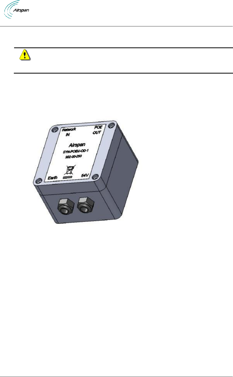
7.1 Connect PSU Output to PoE injector
7.2 Run cables from the PoE injector to the AirSynergy
a) Use this procedure to terminate the -54V DC supply into the PoE injector
Figure 15 – AirSynergy power supply module and connection to the PoE injector

AirSynergy Equipment Installation Guide
Page 25 Commercial in Confidence SYN-UG-007 Rev 1
8 Appendix A
8.1 Review Job Sheet
The Job Sheet should include the following information:
Pole for installation identified
Position on pole identified
Pole access restrictions (highway regulations, other services on pole, power pole)
Method of reaching pole positions (ladders, Elevated work platform)
AC main fuseway available for PSU
Configuration programming details known
Point of connection for Ethernet (if applicable)
All equipment items available at the installation site
o Main AirSynergy unit
o Mounting bracket and pole clamps
o PSU
o PoE injector (with fixing kit)
o Ethernet cable assembly
o GPS Antenna
o GPS antenna installation kit
o Front sector Antenna (if applicable)
o Front sector Antenna mounting bracket ad fixing kit (if applicable)
o External panel antenna (if applicable)
o RF feeder cable tails (if applicable)
Required tools
o Large flat screw driver for pole clamps
o Small flat screwdriver for PoE power terminations
o Small cross-head screwdriver for PoE box lid and fixings for PoE injector and
PSU
o 20mm wrench or small pipe wrench for RF connections
o 10mm wrench for main unit mounting flange nuts
o Side cutters
o Wire strippers
o Krone punch down tool
o Tilt meter to set antenna downtilts
o Ring terminals crimp tool
Required ancilliary equipment
o Lap top PC for initial configuration
o Ethernet cable for temporary connection of the lap top
Other install materials
o Self amalgamating
o Black PVC tape
o Cable ties
o Labels
Whether the system is required to be locked to a GPS timing reference.
A BSID is required for each AirSynergy. This should be in a format xxxxxx:xxxxxx where x
is a decimal digit.

AirSynergy Equipment Installation Guide
Page 26 Commercial in Confidence SYN-UG-007 Rev 1
Network configuration information for the SDR blade. This shall include the following
information for the front panel and the backplane.
o IP Address: Should only be set if Management IP Mode is set to Static IP Address.
See below for Management IP Mode parameter.
o Netmask: Should only be set if Management IP Mode is set to Static IP Address.
See below for Management IP Mode parameter.
o Default Gateway: Should only be set if Management IP Mode is set to Static IP
Address. See below for Management IP Mode parameter.
o Management VLAN: Specified as either Untagged or Tagged
o Management VLAN Tag: Should only be set if Management VLAN is set to Tagged
o Management IP Mode: Specified as Static IP Address or Obtain IP Address via
DHCP
o Ethernet Mode: Specified as Auto-negotiate or Fixed
o Ethernet Rate: Need only be configured if Ethernet Mode is set to Fixed, specified
as 10M or 100M.
o Ethernet Duplex: Need only be configured if Ethernet Mode is set to Fixed,
specified as Full or Half.
SNMP configuration information. This will allow events from the BS to arrive at the
specified Netspan server. This will include the following information:
o Read Only Community: This should be specified to the same value as in Netspan
Discovery Parameters (found under Server on Netspan’s left hand panel).
o Read Write Community: This should be specified to the same value as in Netspan
Discovery Parameters (found under "Server" on Netspan’s left hand panel).
o Community: Normally specified to the same value as for Read Only Community.

AirSynergy Equipment Installation Guide
Page 27 Commercial in Confidence SYN-UG-007 Rev 1
9 Appendix C – Glossary of Terms
AAA
Authentication, Authorization and Accounting
ARQ
Application Function
ASN
Automatic Repeat reQuest
ASN GW
Access Service Network
ASN Gateway
BS
Base Station
BWA
Broadband Wireless Access
CPE
Customer Premises Equipment
FDD
Frequency Division Duplex
GUI
Graphical User Interface
HO
Handover/Handoff
IP
Internet Protocol
MAC
Media Access Control
MIMO
Multiple Input Multiple Output
MS
Mobile Station
NLOS
Non Line of Sight
NSP
Network Service Provider
OFDMA
Orthogonal Frequency Division Multiplexing (Multiple Access)
PHY
PHYsical Layer
SDR
Software Defined Radio
TDD
Time Division Duplex
VoIP
Voice over IP

AirSynergy Equipment Installation Guide
Page 28 Commercial in Confidence SYN-UG-007 Rev 1
10 Appendix D – Checklist
The Checklist below gives the high-level steps in the Workflow for this procedure. Detach or print this
page to use as a job-aid for completing the actions this procedure requires.
Table 3 - Checklist for Procedure
Procedure
Actions
Outcome
1. Verify Prerequisites
Verify site requirements
Verify safety
requirements
Verify installation
requirements
All requirements are in
place for a successful
installation
2. Install AirSynergy
universal mounting plate
Install the universal
mounting plate
Verify connection torque
settings
3. Install AirSynergy on
the mounting plate
4. Connect and manage
cables
Connect AirSynergy PoE
cable
Connect GPS
5. Connect power system
Connect PSU to PoE
injector
Connect Power
Connect Ethernet
backhaul

AirSynergy Equipment Installation Guide
Page 29 Commercial in Confidence SYN-UG-007 Rev 1
11 Appendix E
11.1 Revision History
Revision
Originator
Date
Description
1
J. Forrester
07-2011
Customer Service Help-Desk for customer service emergency
Airspan Networks have introduced the Airspan Tracker application to enable prompt and efficient
Customer Support services.
If you do not have an Airspan Tracker account, please obtain login credentials by filling-in the form in
the main page at www.airspan.com/Support Register New Account.
Worldwide Headquarters:
Airspan Networks Inc.
777, Yamato Road, Suite 310,
Boca Raton, FL 33431, USA
Tel: +1 561 893 8670
www.airspan.com
Feedback:
To provide feedback on this document, please send comments to the following email address:
jforrest@airspan.com