Airspan Communications SCRT-1-49T SCRT User Manual 641661
Airspan Communications Limited SCRT 641661
Contents
- 1. User Guide
- 2. Page from original user manual
User Guide

IP-based
Broadband Wireless Access (BWA) System
605-0000-716 Rev 02
MicroMAX
System OverView
User's Guide
The Innovation Behind Broadband Wireless
Connecting the World
iii
Table Of Contents
System Overview...........................................................................................................1
MicroMAX-SDR Base Station Operation...........................................................................1
MicroMAX-SDR Architecture Overview ............................................................................2
SDR Baseband Sub-system:.......................................................................................2
Single Channel Radio Transceiver (SCRT) RF Subsystem Module: ....................................2
External Antennas: ...................................................................................................2
MicroMAX-SDR Antenna Options....................................................................................2
Technical Overview ........................................................................................................3
Employed Multi-path and Delay-Spread Mitigation Techniques ...........................................3
Spectral Efficiency.......................................................................................................4
Adaptive Modulation ....................................................................................................4
Burst Profiling.............................................................................................................4
STC ..........................................................................................................................4
MRC..........................................................................................................................4
Software Defined Radio using picoChip...........................................................................4
Transport Overview........................................................................................................6
PHY and MAC Layers....................................................................................................6
Security Overview..........................................................................................................7
Security.....................................................................................................................7
System Management......................................................................................................8
Management Options...................................................................................................8
Service Provisioning within Netspan ...............................................................................8
QOS Overview.............................................................................................................10
Applications of QoS within AS.MAX Networks.................................................................10
QoS Utilisation Overview ............................................................................................10
Single Channel Radio Transceiver (SCRT) ........................................................................ 11
Physical ...................................................................................................................11
Interfaces ................................................................................................................11
Software Defined Radio (SDR) .......................................................................................12
Physical ...................................................................................................................12
Interfaces ................................................................................................................12
System Installation ......................................................................................................15
Typical Layout ..........................................................................................................15
Installing the MicroMAX-SDR Enclosure ........................................................................15
Tools Required .......................................................................................................15
Parts Required .......................................................................................................16
MicroMAX-SDR Mounting Plate ....................................................................................16
Mounting the MicroMAX-SDR.......................................................................................17
Mounting the SCRT....................................................................................................17
SDR Connections .........................................................................................................18
Power Input .............................................................................................................18
605-0000-716 MicroMAX User Guide Rev 02
iv
Power Output ...........................................................................................................18
Optic Interface..........................................................................................................18
Ethernet ..................................................................................................................18
Assembly of Connector............................................................................................18
SCRT Connections........................................................................................................20
Power Input .............................................................................................................20
Optic Interface..........................................................................................................20
General ......................................................................................................................21
Warnings and Cautions .................................................................................................21
1. DISCLAIMER.........................................................................................................21
1.1 Safety Warnings .................................................................................................. 21
1.2 Important Warning Symbols..................................................................................21
1.3 Important Service Information............................................................................... 22
1.4 CAUTION............................................................................................................22
1.5 Lightning Protection .............................................................................................22
1.6 FCC RF Exposure .................................................................................................23
Copyright Information ..................................................................................................25
Revisions....................................................................................................................26
Glossary ..................................................................................................................... 27
1
SYSTEM OVERVIEW
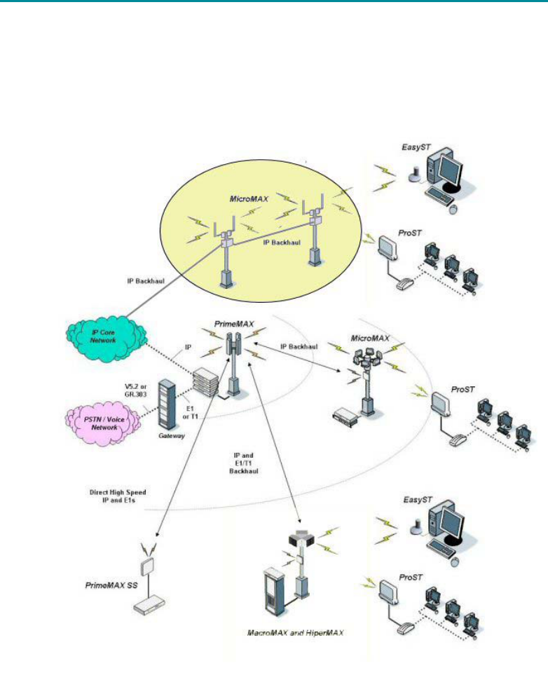
MicroMAX-SDR is highly upgradeable Micro-cell base station, with a pole/roof mounted radio
system and antennae. It forms part of the AS.MAX portfolio of WiMAX network infrastructure
equipment. The diagram below shows MicroMAX-SDR deployed as part of an AS.MAX network. It
is compatible with the Airspan EasyST and ProST subscriber terminals and other manufacturers
CPE that is fully WiMAX compliant.
MicroMAX-SDR Base Station Operation
The MicroMAX-SDR-SDR is designed to be located on utility poles or roof tops providing point to
multi-point WiMAX coverage from an all outdoor base station over micro-cellular ranges to
various CPE types.
The MicroMAX-SDR product is a highly upgradeable micro-Base station, utilizing a software
defined radio (SDR) to enable complete upgradeability of the MAC and PHY. MicroMAX-SDR is
designed for rooftop or pole mounted deployment. The use of separate antennas enables
transmit and receive gain diversity techniques to be utilized, which increases link budget
capability. The MicroMAX-SDR supports both 802.16-2004 for fixed and nomadic applications, as
well as providing a platform for future software upgrades to support WiMAX 802.16e based
profiles for portable and mobile applications.
A MicroMAX-SDR Base Station consists of the following components:

605-0000-716 MicroMAX User Guide Rev 02
2
1x Software Defined Radio (SDR) (including SDR boards plus PSU for SDR + SCRTs)
2x Single Channel RF Transceiver (SCRT)
2x Antenna (customer supplied)
MicroMAX-SDR Architecture Overview
The MicroMAX-SDR Base station consists of a Software Defined Radio (SDR) which includes the
baseband and optional GPS module within a single environmentally protected enclosure. The
SDR is connected to two Single Channel RF Transceivers (SCRF).
SDR Baseband Sub-system:
The baseband sub-system, used within the MicroMAX-SDR Base station, uses the same
technology as the baseband blade fitted within the HiperMAX Base station.
The MicroMAX-SDR modem’s architecture is based on configurable elements, allowing
implementation of a software defined radio, which ensures changes in specification can be
adopted without the need to change the basic hardware construction. Using the approach
based on configurable elements, the MicroMAX-SDR Base station can be upgraded from the
802.16-2004 WiMAX standard to the proposed 802.16e WiMAX standard through the simple
process of upgrading the system software. The PHY processing is implemented using
picoChip technology, whereas the MAC is implemented within two PowerPC processors.
The GPS receiver is a factory build option which is part of the SDR and used to synchronise
Tx & Rx timing between base stations. This is not built into standard SDRs.
Single Channel Radio Transceiver (SCRT) RF Subsystem Module:
The RF subsystem contains two RF, LNA and PA modules for transmit and receive, that
provide either two individually distinguishable sectors or a single sector with diversity. The
RF subsystem connects directly to the baseband module. The SCRT subsystem connects to
the SDR using fibre optic Cable.
External Antennas:
Any suitable external antenna can be used with the MicroMAX-SDR Base station. These
include omni, as well as directional antennas. The antennas can also be vertically or
horizontally polarized.
MicroMAX-SDR Antenna Options
Base Station Antenna Options:
o 2x 60 degree Sector
o 2x 90 degree Sector
o 2x 120 degree Sector
o 2x 180 degree Sector
o 2x Omni-Directional (360 deg)
Vertically polarised for all
Horizontally polarised available for some sector angles – not recommended for a
network consisting of indoor CPE.

System Overview
3
TECHNICAL OVERVIEW
Employed Multi-path and Delay-Spread Mitigation Techniques
MicroMAX-SDR utilizes the cyclic prefix duration included in 802.16 to cater for delay spread and
effects of multi-path. Guard ratios of between ¼ and 1/32 are programmable resulting in peak
delay spread immunity between 2us and 16us respectively for a 3.5MHz channel bandwidth.
802.16e standard will introduce the OFDMA access method. This allows the system to restrict
certain tones within the OFDM waveform to any individual subscriber unit. By avoiding null
traffic channels due to deep fading and/or narrowband interference, the system provides
optimum performance in a multi-path environment. OFDMA enjoys the finest granularity and
better uplink power efficiency than traditional OFDM/TDMA systems. Radio resource allocation is
implemented at the base station and users are notified of the channel assignment through a
multiple access protocol. MicroMAX-SDR is upgradeable to 802.16e via a software upgrade.
Benefits of using Orthogonal Frequency Division Multiple Access
In the uplink each subscriber is assigned 1 to 59 sub-channels. when assigned sub-
channels, a subscriber concentrates its power on these sub-channels.
It solves the Multipath problem and reduces Multipath Interference
It has high Spectral efficiency
It supports smart antenna technology: Smart antennas provide greater capacity and
performance benefits than standard antennas because they can be used to customize
and fine-tune antenna coverage patterns that match the traffic conditions in a wireless
network or that are better suited for complex radio frequency (RF) environments.
Furthermore, smart antennas provide maximum flexibility by enabling wireless network
operators to change antenna patterns to adjust to the changing traffic or RF conditions
in the network.
o RX/TX antenna diversity
o Space Time Coding (STC)
It is an efficient modulation
o QPSK, QAM16, QAM64 per sub carrier
o FEC rates ranging from 1/2 to 3/4
o Guard intervals of 1/32, 1/16, 1/8 and 1/4
Supports adaptive modulation on a per subchannel basis
The efficient use of pilots minimizes requirement for preambles for channel estimation
External, narrow band interference is rejected through frequency domain processing
External, burst interference is rejected by virtue of the OFDMA symbol length and the
per sub-channel interleaving
Inter-cell interference is mitigated by use different sub-carriers in sub-channels

605-0000-716 MicroMAX User Guide Rev 02
4
Spectral Efficiency
The network spectral efficiencies for MicroMAX-SDR, MicroMAX-SDR and HiperMAX assuming
3.5MHz FDD channels are as follows:
Gross Throughput (Mb/s) Mod/FEC
Downlink Uplink
Occupied
Bandwidth
(Mhz)
Spectral
Efficiency
(b/s/Hz) per
RF Channel
64QAM3/4 13.1 13.1 3.5 3.7
64QAM1/2 11.5 11.6 3.5 3.3
16QAM3/4 8.7 8.7 3.5 2.5
16QAM1/2 5.8 5.8 3.5 1.7
QPSK3/4 4.4 4.4 3.5 1.3
QPSK1/2 2.9 2.9 3.5 0.8
BPSK1/2 1.4 1.4 3.5 0.4
Note: Figures above are based on Gross throughput. Maximum achievable net throughput is in
the region of 85% of gross downlink throughput and 75% of gross uplink throughput which is
required to accommodate overhead including Pre-amble, DL&UL Maps, DLFP and Mid-ambles.
Adaptive Modulation
Adaptive modulation techniques, for maximizing system throughput by monitoring link quality
and selecting the highest usable adaptive burst profile, are used throughout the MicroMAX-SDR
product range. Within each burst, data transmitted over the air is padded with redundant
information to make it more resistant to errors introduced by interference. The coding rate is
the ratio of user-data to the total data transmitted (which includes redundant error correction
data. Protocol features allow for adaptive modulation to be employed in both downlink and
uplink. Modulations ranging BPSK 1/2 to 64QAM 3/4 may be employed.
Burst Profiling
All MicroMAX-SDR Base stations, operating using FDD or TDD in the downlink and uplink support
burst profiles which are adaptive on a per terminal basis. Burst profiles are used to define
modulation and FEC levels using the DCD and UCD messaging schemes and are invoked through
downlink and uplink MAP messaging. RF link control functions within the Base station and the
ST continuously monitor receiver SNR and adapt modulation accordingly.
STC
Space Time Coding is a method of transmit diversity using two antennas, is used within the
MicroMAX-SDR product. This mode may be used to improve link robustness.
MRC
Maximal-ratio combining is a form of diversity combiner in which (a) the signals from each
channel are added together, (b) the gain of each channel is adjusted to ensure each channel is
proportional to the rms signal level in each channel and inversely proportional to the mean
square noise level in that channel, and (c) the same proportionality constant is used for all
channels.
Software Defined Radio using picoChip
MicroMAX-SDR Base stations are fully upgradeable and future-proof due to the use of picoChip
technology. PicoChip provides high performance processing arrays which have been optimized
for use within the wireless industry. This enables the complete radio and digital signal
processing functions to be soft-defined within devices which have replaced the need to
incorporate inflexible FPGA and ASIC silicon. PicoChip devices are fully reprogrammable to allow

System Overview
5
the 802.16 PHY to be completely upgraded, through the use of a simple software download, as
the WiMAX standard evolves. Using picoChip, the ASMAX MicroMAX-SDR Base stations will
always remain compliant with this emerging standard.
Key benefits of using picoChip within the MicroMAX-SDR Base stations:
Software defined: Fully Scalable & Future Proof
Full support for 802.16-2004 (256 OFDM PHY)
Upgradeable to 802.16e to support hand held devices
Support for 1X scalable PHY & OFDMA
FDD or TDD; 3.5MHz / 7MHz / 10MHz
Software defined RF (industry standard OBSAI RP3-01 interface)
Advanced feature options: Smart antennas & diversity, SDMA

605-0000-716 MicroMAX User Guide Rev 02
6
TRANSPORT OVERVIEW
PHY and MAC Layers
The IEEE 802.16 standard covers both the Media Access Control (MAC) and the physical (PHY)
layers. The RF, PHY, and MAC layers control Link capacity and the MAC, IP, and Application
Layers control system capacity.
Application
IP
MAC
PHY
Radio
AS.MAX product is packet based and supports any packets, including PPPoE, IPX, NetBIOS as
well as IP and is designed for very high bit rates (up to 268 Mbps each way) of the broadband
physical layer. The MAC layer organises the use of radio resources and allows terminals to be
dynamically assigned uplink and downlink burst profiles according to their link conditions. This
allows a trade-off between capacity and robustness in real-time while maintaining appropriate
link availability. It performs link adaptation and Automatic Repeat Request (ARQ) functions to
maintain target Bit Error Rates (BER) while maximizing the data throughput. The MAC layer also
handles network entry for ST’s that enter and leave the network, and it performs standard
Protocol Data Unit (PDU) creation tasks. Finally, the MAC layer provides a convergence sub layer
that supports packet-based network layers.
The 802.16 MAC uses a variable length Protocol Data Unit (PDU) along with a number of other
concepts that greatly increase the efficiency of the standard. Multiple MAC PDUs may be
concatenated into a single burst to save PHY overhead. Additionally, multiple Service Data Units
(SDU) for the same service may be concatenated into a single MAC PDU, saving on MAC header
overhead. Fragmentation allows very large SDUs to be sent across frame boundaries to
guarantee the QoS of competing services. And, payload header suppression can be used to
reduce the overhead caused by the redundant portions of SDU headers.
The MAC also provides Quality of Service (QoS) differentiation, using a self-correcting
bandwidth request/grant scheme to eliminate the overhead and delay of acknowledgements,
while simultaneously allowing better QoS handling than traditional acknowledged schemes.
Terminals have a variety of options available to them for requesting bandwidth depending upon
the QoS and traffic parameters of their services. They can be polled individually or in groups.
They can steal bandwidth already allocated to make requests for more. They can signal the
need to be polled, and they can piggyback requests for bandwidth.

System Overview
7
SECURITY OVERVIEW
Security
The AS.MAX security methods are derived from those defined by IEEE 802.16-2004. DES in
cipher block chaining (CBC) mode and AES in counter CBC-MAC (CCM) mode (in future release)
are used to encrypt the payload of MPDUs on transport and secondary management
connections. The Privacy Key Management (PKM) protocol is used for certificate-based
authorization of the SS and to perform secured transfer of keys between the BS and the SS.
Since the encipherment process takes place over the payload of the MPDU, all the details of
fragmentation, packing, grant requests and ARQ are hidden.
The PKM protocol is based on Public Key Infrastructure (PKI), which uses digital certificates and
RSA public key methods to authenticate an SS to a BS. The SS provides its X.509 certificate to
the BS, thus revealing its identity and public key to the BS. The BS returns an authorization key
(AK) to the SS, encrypted by the SS public key using RSA algorithm. The SS can decrypt the AK
using its private key. The authorization key is then used to derive key encryption key (KEK).
The SS and BS, since they both know the AK can derive the same KEK.
To transfer a traffic encryption key (TEK) from the BS to the SS, the TEK is encrypted using the
KEK with 3-DES in EDE mode algorithm (when data is DES encrypted) or with AES in ECB mode
algorithm (when data is AES encrypted).
605-0000-716 MicroMAX User Guide Rev 02
8
SYSTEM MANAGEMENT
Management Options
The AS.MAX WiMAX compliant platform supports three management options:
Local web based client management of individual system components
o Used to configure small systems and networks
Management via third party SNMP management tool
o Uses standard WiMAX MIB
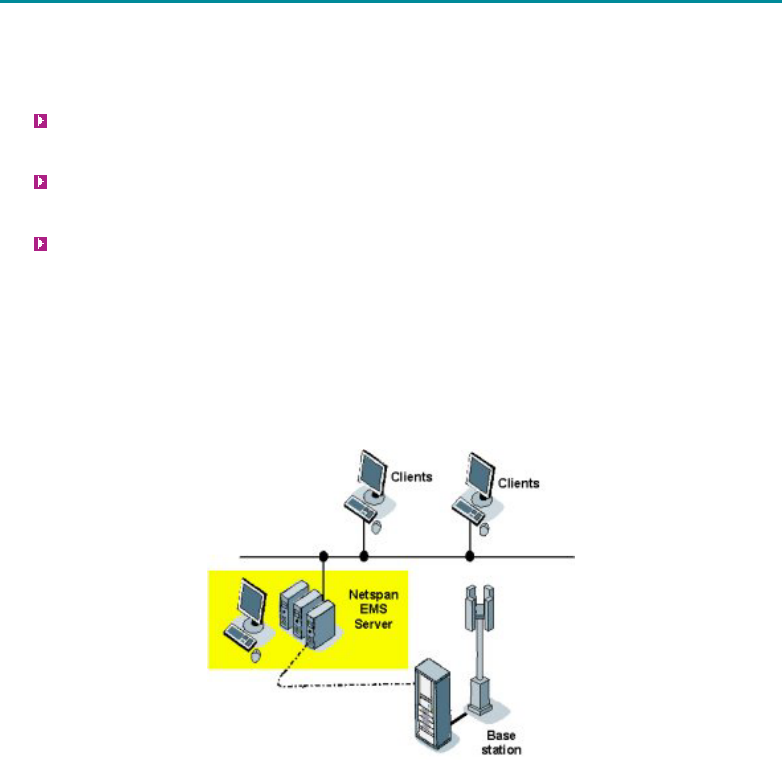
Airspan’s Netspan network management server
o Already running numerous BWA networks worldwide
o Based on Microsoft.net platform
o Distributed server architecture support
o Full system configuration, operation and maintenance via standard web client
o SNMP API support
o Uses standard WiMAX MIB for all configuration and O&M activities
Server: Supports an SQL database for configuration & alarm storage with an option
for 3rd party access direct to database via SNMP.
Client: Accessed via Internet Explorer or other compatible browser software and
connects to the server via IP.
Service Provisioning within Netspan
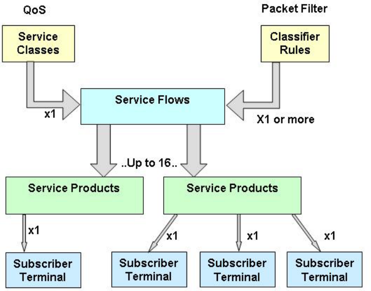
As shown in the diagram below, Service Flows are assigned to a Subscriber Terminal (ST) by
defining a ‘Service Product’. Each Subscriber Terminal has a single Service Product to define the
capacity and capability associated with the service delivered to each customer. Within the IEEE
802.16-2004 standard a Service Product can define up to sixteen Service Flows which provisions
the types of service (web browsing, VoIP, FTP, etc) delivered via each Subscriber Terminal.
Detailed QoS specification is defined within the Service Class and the filters which tag a level of
QoS to a particular flag or packet type is defined within the Classifier Rules. A single QoS rule
defined within the Service Class can be associated with one or more Classifier Rule(s).
System Overview
9

605-0000-716 MicroMAX User Guide Rev 02
10
QOS OVERVIEW
Applications of QoS within AS.MAX Networks
The AS.MAX platform provides a broadband connection which will support many and varied
applications, some of which require specific performance guarantees to ensure the network
sustains the subscriber’s expectations regarding the viability and usability of the service. Such
applications include:
Voice telephony
Video telephony
Video streaming
On-line gaming
To ensure a broadband network can credibly provide these services a viable quality of service
policy needs to be implemented within the network. The AS.MAX network is fully compliant with
the QoS requirements identified within the IEEE 802.16-2004 standard. Taking a voice
telephony service as an example, the QoS facility implemented within the AS.MAX product range
ensures the architecture can provide a subjective and measured quality in the control plane and
the user plane that is comparable with traditional PSTNs based on analogue access and TDM-
based digital exchanges. Specifically, QoS mechanisms built into the AS.MAX platform ensure
the following characteristics, associated with a voice service delivered over a PSTN, are
maintained:
Call progress delays are comparable with those in the PSTN, including (but not limited
to):
Off-hook to application of dial tone.
First dialed digit to removal of dial tone.
Completion of dialing to alert at the called end.
Completion of dialing to application of ringing tone at the calling end.
Completion of dialing to application of busy tone at the calling end.
The probability of blocking call attempts for reasons other than exhaustion of resources
is low.
Once a call has been accepted, quality is comparable with the PSTN, including (but not
limited to):
Probability of call cut-off.
Absolute voice-path latency.
Variance (jitter) in voice-path latency.
Non-linear distortion and/or signal-to-noise ratio.
Subjective voice quality measures such as Mean Opinion Score (MOS).
Compatibility with voice-band modems and facsimile machines.
Rate of impulse noise.
Probability of audio drop outs.
Once a call has been accepted, subjective and measured quality is maintained
regardless of:
Loading of the telephony service.
Overall loading of the AS.MAX network.
QoS Utilisation Overview
A packet scheduling algorithm is incorporated within the AS.MAX network which will support
MIR, CIR and packet prioritization functionality, as well the specification of overall packet
latency.

System Overview
11
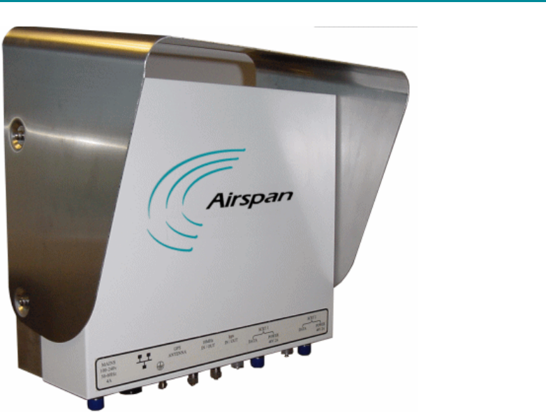
SINGLE CHANNEL RADIO TRANSCEIVER (SCRT)
Physical
Base Station SCRT (excl bracket): 340 x 270 x 140mm
Weight: 7.5kg maximum
Interfaces
SCRT Fibre Interface:
Weatherproof Fibre Optic Proprietary Connection Fibre interface is dependant upon SFP
fitted (factory fit). Standard SFPs support 768MB/s fibre connections.
SCRT Power Interface:
Weatherproof Proprietary Connection compatible with connector supplied as part of Airspan
MicroMAX-SDR Installation Kit
RF Port:
Connector: N-Type Female
Impedance: 50ohms
Minimum In-band Return Loss:15dB
605-0000-716 MicroMAX User Guide Rev 02
12
SOFTWARE DEFINED RADIO (SDR)
Physical
Base Station SDR: 355 x 430 x 165mm
Weight: 25kg maximum
Interfaces
Network Ethernet Interface:
IEEE 802.3 10bT/100bT auto switching RJ45 connections with weatherproof proprietary
seal. Note: There is no physically separate Network Management port. Network
Management Traffic can be separated using suitable VLAN tagging.
SDR Fibre Interface:
Weatherproof Fibre Optic Proprietary Connection Fibre interface is dependant upon SFP
fitted (factory fit). Standard SFPs support 768MB/s fibre connections.
SDR Power out Interface:
Weatherproof Proprietary Connection compatible with connector supplied as part of
Airspan MicroMAX-SDR Installation Kit
GPS Antenna:
GPS synchronisation is a factory build option for the SDR. Standard SDRs do not include
the GPS option.
Connector: N-Type Female
Impedance: 50 ohms

System Overview
13
AC Mains Power Input:
1m flying mains lead provided for connection to external junction box. 85V to 265V AC
47-63Hz Single Phase
3 conductors as follows:
Connection ALL COUNTRIES EXCEPT
JAPAN
JAPAN
Earth
(Ground)
Green/Yellow RED:
Neutral
(Cold)
Blue WHITE:
Live (Hot) Brown BLACK:
Power Consumption (1xSDR + 2x SCRT): 220 Watts maximum

15
SYSTEM INSTALLATION
Typical Layout
MicroMAX-SDR uses two physically separate antennas to provide diversity on uplink and
downlink:
Receive: Supports two path Maximum Ratio Combining (MRC)
Transmit: Transmit signals are delayed by a constant timing offset for diversity.
To optimise diversity performance, it is recommended that antennas are separated on the
azimuth plane by between 10 and 20 wavelengths. At 4.9GHz, this equates to a separation of
between 610 and 1220mm.
Note: Design and provision of the infrastructure is the responsibility of the Network Provider.
Installing the MicroMAX-SDR Enclosure
Tools Required
Tool
1* Large Crosshead Screw
driver
Phillips # 3 or Pozidrive # 3
605-0000-716 MicroMAX User Guide Rev 02
16
Parts Required
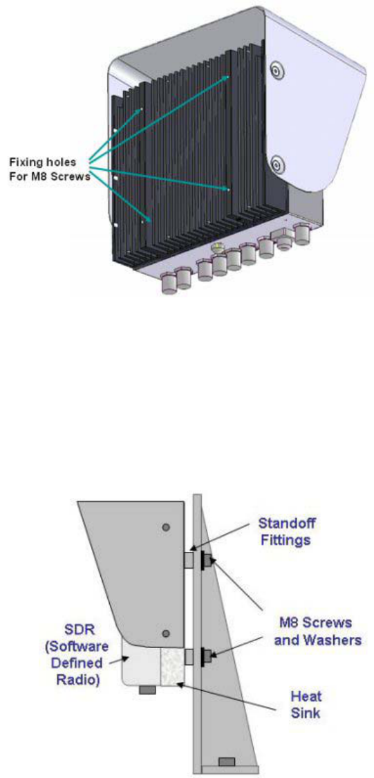
SDR Installation Kit per
SDR consisting of:
4* M8 Screws and Washers
4* M8 Standoff Fittings
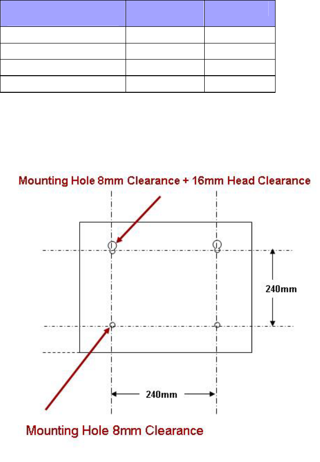
MicroMAX-SDR Mounting Plate
The SDR enclosure is fitted on to the Mounting Plate (Not provided by Airspan). The
mounting should be drilled as shown below.
System Installation
17
Mounting the MicroMAX-SDR
1. Screw the four standoff fittings into the 8mm mounting holes on the heat sink of the
SDR enclosure.
2. Loosely place two of the M8 screws and washers into the two standoff fittings at the top
of the SDR enclosure.
3. Lift the enclosure and place the screws through the head clearance holes and lower the
unit so that the top mounting holes retain the unit. Note: This unit weighs 25kg take
care when lifting.
4. Screw the bottom two the M8 screws and washers into the two standoff fittings at the
bottom of the SDR enclosure.
5. Tighten all fixing screws.
Mounting the SCRT
605-0000-716 MicroMAX User Guide Rev 02
18
SDR CONNECTIONS
Power Input
85V to 265V AC 47-63Hz Single Phase. The power input is via a plug and a 1m lead. The three
conductors are as follows:
Connection ALL COUNTRIES EXCEPT
JAPAN
JAPAN
Earth
(Ground)
Green/Yellow RED:
Neutral
(Cold)
Blue WHITE:
Live (Hot) Brown BLACK:
Power Output
Each SCRT is provided with a 3 metre 48 volt power cable terminated with a male connector at
one end and a female connector at the other. The male connector attaches to the SDR and the
female connector attaches to the SCRT.
Optic Interface
Each SCRT is provided with a 3 metre optical fibre cable, ready terminated with optical
connectors. Unscrew the protective dust cap and screw the fibre optic cable in place.
Ethernet
The Ethernet cable is connected to the SDR using a standard RJ45 connector protected by a
harsh environment protective casing.
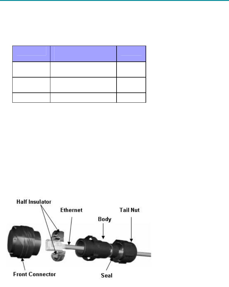
Assembly of Connector
1. Terminate the Ethernet cable with an RJ45 connector plug.
2. Pass the RJ45 plug through the tail nut, seal and body of the environmental connector.
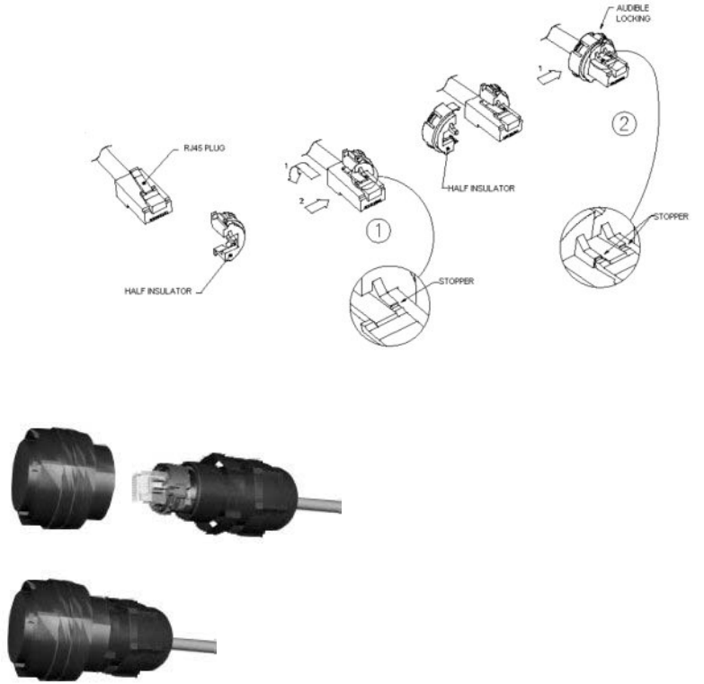
3. Place the half insulators around the RJ45 connector plug as shown below .
a) Push down the cordset latch on the RJ45 connector
b) Place one of half of the insulators onto the RJ45
c) Place the second half of the insulator to meet the first half. Push firmly
together until an audible click indicates that they are locked.
System Installation
19
4. Feed back the cable so that the retainers fit onto the body of the environmental
connector.
5. Tighten the tail nut on to the body forcing the seal to compress around the cable.
6. Screw the front connector onto the body of the environmental connector.
7. Push the assembled connector on to the Ethernet socket of the SDR.

605-0000-716 MicroMAX User Guide Rev 02
20
SCRT CONNECTIONS
Power Input
Each SCRT is provided with a 3 metre 48 volt power cable terminated with a male connector at
one end and a female connector at the other. The female connector attaches to the SCRT and
the male connector attaches to the SDR .
Optic Interface
Each SCRT is provided with a 3 metre optical fibre cable, ready terminated with optical
connectors. Unscrew the protective dust cap and screw the fibre optic cable in place.

21
GENERAL
WARNINGS AND CAUTIONS
1. DISCLAIMER
Every effort has been made to ensure the accuracy of the material provided herein;
however, Airspan Networks Inc. assumes no responsibility regarding the use of the
material. Additionally, Airspan Networks Inc. makes no representations or warranties,
either expressed or implied, regarding the contents of this product. Airspan Networks
Inc. shall not be liable for any misuse regarding this product.
1.1 Safety Warnings
1. Read this User Manual and follow all operating and safety instructions.
2. Keep all product information for future reference.
3. This product is supplied with a grounding power plug. Do not defeat this important
safety feature.
4. Always replace the fuse with the correct type and current rating.
5. Position the power cord to avoid possible damage; do not overload wall outlets.
6. Do not place this product on or near a direct heat source, and avoid placing objects on
the terminal.
7. Do not operate this device near water or in a wet location.
8. Use only a damp cloth for cleaning. Do not use liquid or aerosol cleaners. Disconnect
the power before cleaning.
9. Protect the terminal by disconnecting the power if not used for long periods.
10. Mount the terminal in a Telco rack on a stable horizontal surface.
11. The radio antenna units must not be located near power lines or other electrical power
circuits.
12. The radio transceiver must be properly grounded to protect against power surges and
accumulated static electricity. It is the user’s responsibility to install this device in
accordance with the local electrical codes: correct installation procedures for grounding
of the transceiver unit, mast, lead-in wire and discharge unit, location of discharge unit,
size of grounding conductors and connection requirements for grounding electrodes.
13. Installation of the transceiver and antenna must be contracted to a professional
installer.
14. Disconnect Device. The socket outlet shall be installed near the equipment , easily
accessible and will act as the disconnect for the MacroMax.
15. When installed in the final configuration, the product must comply with the applicable
Safety Standards and regulatory requirements of the country in which it is installed. If
necessary, consult with the appropriate regulatory agencies and inspection authorities
to ensure compliance.
1.2 Important Warning Symbols
The following symbols may be encountered during installation or troubleshooting. These warning
symbols mean danger. Bodily injury may result if you are not aware of the safety hazards
involved in working with electrical equipment and radio transmitters. Familiarize yourself with
standard safety practices before continuing.
Electro-Magnetic Radiation High Voltage
605-0000-716 MicroMAX User Guide Rev 02
22
1.3 Important Service Information
1. Refer all repairs to qualified service personnel. Do not remove the covers or modify any
part of this device, as this will void the warranty.
2. Disconnect the power to this product and return it for service if the following conditions
apply:
a. The terminal does not function after following the operating instructions outlined in this
manual.
b. Liquid has been spilled, a foreign object is inside, or the terminal has been exposed to
rain.
c. The product has been dropped or the housing is damaged.
3. Locate the serial number of the terminal, antenna, and transceiver and record these on
your registration card for future reference. Use the space below to affix serial number
stickers. Also record the MAC address, located on the back of the terminal.
1.4 CAUTION
Any modifications to this device not expressly authorised by the manufacturer could void
the user's authority to operate this device.
Responsible party for compliance is:
David Mann, Airspan Networks Inc.,Cambridge House, Oxford Rd, Uxbridge, Middlesex,
England, UB8 1UN. Telephone (44) 1 895 467450.
1.5 Lightning Protection
WARNING: The following notes are general recommendations for the system. The
wireless equipment should be installed by a qualified professional installer and must
follow local and national codes for electrical grounding and safety. Failure to meet safety
requirements and/or use of non-standard practices and procedures could result in
personal injury and damage to equipment. A direct lightning strike may cause serious
damage even if these guidelines are followed.
All outdoor wireless equipment is susceptible to lightning damage from a direct hit or
induced current from a near strike. Lightning protection and grounding practices in local
and national electrical codes serve to minimize equipment damage, service outages, and
serious injury. Reasons for lightning damage are summarized as:
- Poorly grounded tower/antenna sites that can conduct high lightning strike energy into
equipment.
- Lack of properly installed lightning protection equipment that can cause equipment
failures from lightning induced currents.
A lighting protection system provides a means by which the energy may enter earth
without passing through and damaging parts of a structure. A lightning protection system
does not prevent lightning from striking; it provides a means for controlling it and
preventing damage by providing a low resistance path for the discharge of energy to
travel safely to ground. Improperly grounded connections are also a source of noise that
can cause sensitive equipment to malfunction.
A good tower grounding system disperses most of the surge energy from a tower strike
away from the building and equipment. The remaining energy on the RF cable shield and
center conductor can be directed safely to ground by using a lightning arrestor in series
with the RF cable.
To limit the equipment damage due to a lightning strike, the following practices are
recommended for the wireless system:
- Provide direct grounding from the antenna mounting bracket, the radio and antenna
and the lightning arrestors to the same ground point at the base of the tower or a ground
bus on the building. Use the grounding screws on the antenna bracket and the radio and
antenna for terminating the ground wires.
General
23
- Install one RF lightning protector between the radio and antenna in series with the RF
cable.
- A lightning arrestor in series with the RF cable at the point of entry to the building.
- Install a lightning arrestor in series with the IF cable at the transceiver on the
tower/mast.
- The AC wall outlet ground for the MacroMAX terminal must be connected to the same
grounding system as the radio and antenna lightning protectors.
1.6 FCC RF Exposure
FCC Maximum Permissible Exposure (MPE) limits for equipment operating in the
frequency range 1500 – 100,000 MHz is 1.0 mW/cm2.
Following installation and commissioning, the safe distance from the antenna is the
greater of:
20cm
Or
r cm, where r = √ (PG/4∏S)
P: power input to antenna in mW = 166mW
G: numeric gain of antenna relative to isotropic radiator
S: power density in mW/cm2 = 1 mW/cm2
Therefore, safe distance from the antenna shall be the greater of
20 cm or √ (13.21*G) cm.

605-0000-716 MicroMAX User Guide Rev 02
24
Contact Information
UK Office for sales and general enquiries
Airspan Communications Ltd
Cambridge House
Oxford Road
Uxbridge
Middlesex
UB8 1UN
Call +44 (0) 1895 467100
Fax +44 (0) 1895 467101
email sales@ airspan.com
Internet: Airspan.com
Customer Service Help-Desk for customer service emergency
Airspan Communications Limited
Cambridge House
Oxford Road
Uxbridge
Middlesex
UB8 1UN
Int. Tel: +44 (0) 1895 467 467
Int. Fax: +44 (0) 1895 467 472
E-mail: Support@Airspan.com

General
25
COPYRIGHT INFORMATION
1. Airspan Networks Inc 2005
2. The information in this document is proprietary to Airspan Networks Inc. This document
may not in whole or in part be copied, reproduced, or reduced to any medium without
prior consent, in writing, from Airspan Networks Incorporated.
3. This manual is subject to revision.
4. All rights reserved.
5. Right of modification reserved.
6. This manual is supplied without liability for errors or omissions.
7. No part of this manual may be reproduced or used except as authorised by contract or
other written permission.
8. This equipment is conditioned by the requirement that no modifications are made to the
equipment unless the changes or modifications are expressly approved by Airspan
Networks
9. Prerequisite skills: Personnel installing, commissioning, and maintaining
Airspan products must have a basic knowledge of telephony and radio communications,
and have experience in installing, commissioning and maintaining telecommunications
products. Airspan provides a range of comprehensive training courses specifically aimed
at providing operators/users of Airspan products with the prerequisite skills to install,
commission and or maintain the product. The courses are tailored to provide the level
of training required by the operator/user.
10. AS4000, AS4020 and AS8200 are brands of Airspan Networks Inc

605-0000-716 MicroMAX User Guide Rev 02
26
REVISIONS
Revision
Level
Date Main Changes
01 25-9-
2005
Initial Document
02 18-10-
2005
AC cable colour code for ROW added
27
GLOSSARY
A
AAS : Adaptive antenna system (see Introduction for further details)
AP : Access point
API : Application programmers interface
ATCA : Advanced telecommunications computing architecture
B
BE : Best effort scheduling service for requesting uplink bandwidth
BER : Bit error rate
BS : Base station
BWA : Broadband wireless access
C
CIR : Committed information rate used to specify the guaranteed data rate to the customer.
CPE : Customer premises equipment (interchangeable with ST)
D
DCD : Downlink channel descriptor
DFS : Dynamic frequency selection (see Introduction for further details)
DL : Downlink
DLFP : Downlink frame prefix
E
E1 : ITU term for a 2Mb/s pulse code modulated transmission link
EiRP : Effective isotropic radiated power
F
FCH : Frame control header
FDD : Frequency division duplex
FEC : Forward error correction
FFT : Fast Fourier transform used to convert a signal from the time domain into the frequency
domain
H
H-FDD : Half duplex FDD
I
IAD : Integrated access device
IP : Internet protocol
605-0000-716 MicroMAX User Guide Rev 02
28
K
Kb/s : Kilobits per second
M
MAC : The next layer up from the PHY, known as the media access controller
Mb/s : Megabits per second
MIB : Management interface block
MIMO : Multiple-in, multiple-out
MIR : Maximum information rate used to specify the maximum data throughput to a customer.
MRC : Maximal-ratio combining
N
NLOS : None line of sight radio propagation path
NRTP : Non real time polling is similar to real time polling but is used to request uplink
bandwidth less regularly
O
O&M : Operations and maintenance
ODU : Out door unit associated with a ST
OFDM : Orthogonal frequency division multiplexing
P
PHY : The physical layer associated with the WiMAX interconnection stack
PMP : Point to multipoint radio systems architecture
PoE : Point to point protocol over Ethernet
PtP : Point to point radio systems architecture
Q
QoS : Quality of service, which is used to specify level of data throughput
R
REC : Radio equipment controller
RTP : Real time polling allows a service flow to request uplink bandwidth at regular intervals
Rx : Receiver
S
SDMA : Space division multiple access is a technique which makes it possible to increase the
capacity of a cellular mobile radio system by taking advantage of spatial separation
between users
SDR : Software defined radio
SF : Service flow
SME : Small to medium sized enterprise
Glossary
29
SNMP : Simple network management protocol
SNR : Signal to noise
SOFDMA : Scaleable orthogonal frequency division multiplexing
SoHo : Small office/home office
SS : Subscriber station (interchangeable with CPE or ST)
ST : Subscriber terminal (interchangeable with CPE or SS)
STC : Space time coding
T
T1 : North American standard 1.56Mb/s pulse code modulated transmission link
TDD : Time division duplex
TDM : Time division multiplexing
Tx : Transmitter
U
UCD : Uplink channel descriptor
UGS : Unsolicited grant service used to provide fixed bandwidth slots on the uplink for an ST to
transmit data at regular intervals. The bandwidth should be used by the UGS SF,
however the final decision of which SF (if any) uses the bandwidth slot is made by the
ST.
V
VoIP : Voice over Internet protocol
W
WiMAX : WiMAX is a wireless industry coalition whose members are organized to advance IEEE
802.16 standards for broadband wireless access (BWA) networks.
WipLL : Wireless Internet protocol in the local loop product range currently available and
offered by Airspan.

31
How to find out
more
about
Airspan products
and solutions
Airspan has offices in the following
countries:
Europe
Czech Republic
Poland
Russia
United Kingdom
Africa
South Africa
Americas
United States
Asia Pacific
Australia
China
Indonesia
Japan
New Zealand
For more information about Airspan, its
products and solutions, please visit our
Web site:
www.airspan.com
Or write to us at one of the addresses
below.
We will be delighted to send you
additional
information on any of our products and
their
applications around the world.
Worldwide Headquarters:
Airspan Networks Inc.
777 Yamato Road, Suite 105
Boca Raton, Florida 33431-4408
USA
Tel: +1 561 893 8670
Fax: +1 561 893 8671
Main Operations:
Airspan Communications Ltd.
Cambridge House, Oxford Road,
Uxbridge, Middlesex UB8 1UN
UK
Tel: +44 (0) 1895 467 100