Airspan Communications STODU-PCS Subscriber Terminal User Manual 605 0000 595 ST Installation and Commissioning
Airspan Communications Limited Subscriber Terminal 605 0000 595 ST Installation and Commissioning
User Manual

605-0000-595 Subscriber Terminal
Installation and Commissioning
i
Table Of Contents
AS4000 STs .....................................................................................................................1
AS4000 Subscriber Terminal Overview .......................................................................1
Subscriber Terminal Products.....................................................................................6
The B Series Service Interface Unit.............................................................................8
The L Series Service Interface Unit .............................................................................9
The M Series Modular Service Interface Unit ............................................................. 10
The N Series Service Interface Unit........................................................................... 11
The P Series Subscriber Terminal............................................................................. 12
The R Series Residential Service Interface Unit(Plastic Case) .................................... 14
The R Series Residential Service Interface Unit (Metal Case)..................................... 15
The S Series Sub Unit Service Interface Unit............................................................. 17
V Series .................................................................................................................. 18
W Series ................................................................................................................. 19
Specifications .......................................................................................................... 21
AS4020 STs ................................................................................................................... 23
AS4020 Subscriber Terminal Overview ..................................................................... 23
AS4020 Subscriber Terminal Products...................................................................... 26
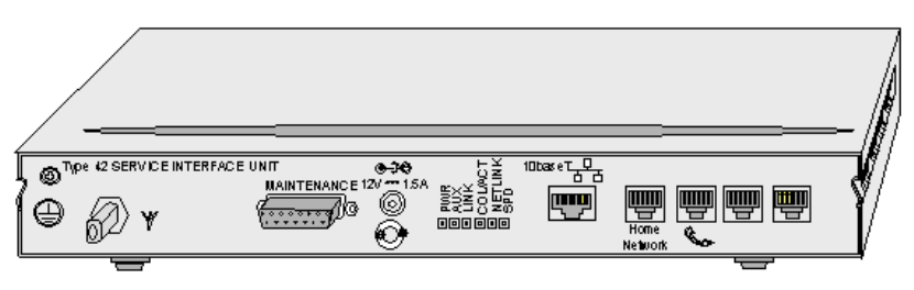
Type 42 ...................................................................................................................... 27
Type 42 Overview.................................................................................................... 27
The P Series Subscriber Terminal............................................................................. 30
W Series ................................................................................................................. 31
V Series .................................................................................................................. 33
Specifications .......................................................................................................... 35
Installation...................................................................................................................... 37
Pre-installation......................................................................................................... 37
Installation Steps ..................................................................................................... 38
Preparation ................................................................................................................. 40
Site Selection .......................................................................................................... 40
Unpacking and Inspection ........................................................................................ 43
Required Tools and equipment. ................................................................................ 44
Installing Outdoor Unit ................................................................................................. 46
Installing the Wall Mount Outdoor Unit Using Bracket 605-0010-279/280. .................... 46
Installing the Outdoor Unit Using Bracket 605-0010-283 ............................................ 52
Installing The Pole Mount Outdoor Unit ..................................................................... 57
Installing the IF Unit for External Antenna .................................................................. 60
Installing Drop Cable ................................................................................................... 63
Drop Cable Installation ............................................................................................. 63
Drop Cable Termination Using Crimp Type Connectors .............................................. 66
Drop Cable Termination Snap and Seal Connectors................................................... 68
Drop Cable Termination using RG11 Snap and Seal Connectors ................................ 69
Installing PSUs............................................................................................................ 70
Type 6 PSU............................................................................................................. 70
Type 7 PSU............................................................................................................. 71
Installing AS4000 SIUs ................................................................................................ 74
Installing B Series SIU.............................................................................................. 74
Configuring the S-Bus.................................................................................................. 76
Installing L Series SIU .............................................................................................. 77
Installing the M Series Module Enclosure .................................................................. 81
Installing N Series SIU.............................................................................................. 97
Installing P Series SIUs ..........................................................................................101
Installing The R series Service Interface Unit and PSU. .............................................106
Installing R Series SIU NU-V1/V2.............................................................................111
Installing the S Series SIU.......................................................................................114
Installing V Series SIUs ..........................................................................................118
Installing W series SIU ............................................................................................122
Installing AS4020 SIUs ...............................................................................................126
Installing P Series SIUs ..........................................................................................126
Installing V Series SIUs ..........................................................................................131
Table Of Contents
ii
Installing W series SIU ............................................................................................135
Commissioning..............................................................................................................139
Commissioning Steps..............................................................................................139
Type 41 and earlier.....................................................................................................141
Programming Subscriber Terminal Using STMON....................................................141
Programming SIU using a test telephone. ................................................................145
Panning Outdoor Unit using a AS7020 STMON for Windows .....................................150
Panning a Type 41 Outdoor Unit Using STMeter.......................................................156
Panning Outdoor Unit Using a DVM .........................................................................158
Checking for Fade Margin using a Fader Cap (optional). ...........................................159
Functional Tests .....................................................................................................160
Test Results Type 41 ..............................................................................................162
AS4000 Subscriber Terminal Acceptance Form ........................................................165
Type 42 .....................................................................................................................166
Pre-installation........................................................................................................166
Programming SIU using a test telephone. ................................................................167
Programming Type 42 ST using STMON.................................................................173
Configure a Type 42 Subscriber Terminal........................................................................173
Panning Type 42 Outdoor Unit Using STMON ..........................................................176
Panning a Type 42 Outdoor Unit using STMeter .......................................................180
Panning Outdoor Unit Using a DVM .........................................................................182
Service Testing.......................................................................................................183
Test Results Type 42 ..............................................................................................184
AS4000 Subscriber Terminal Acceptance Form ........................................................186
ST W Setup ...............................................................................................................187
Commissioning the ST W ........................................................................................187
Configuring the ST W..............................................................................................190
Managing the ST W ................................................................................................196
Reset Options.........................................................................................................204
Set Up Access Parameters ......................................................................................206
VPNs .....................................................................................................................207
Encryption ..............................................................................................................209
Advanced Features .................................................................................................210
Software Downloads ......................................................................................................213
Software Download Using STMON...........................................................................213
Over the Air Software Downloads.............................................................................215
STMeter........................................................................................................................217
Connecting the STMeter to the SIU..........................................................................217
Menu......................................................................................................................218
Software Upgrade for STMeter ................................................................................219
General.........................................................................................................................223
Notes for Users.......................................................................................................223
Glossary .......................................................................................................................225
Index ............................................................................................................................229

23
AS4020 STs
AS4020 Subscriber Terminal Overview
The AS4020 Subscriber Terminal (ST) portfolio includes subscriber terminal types for voice,
and packet data. In general, the customer has access to the same range of facilities that are
supported by a conventional copper pair.
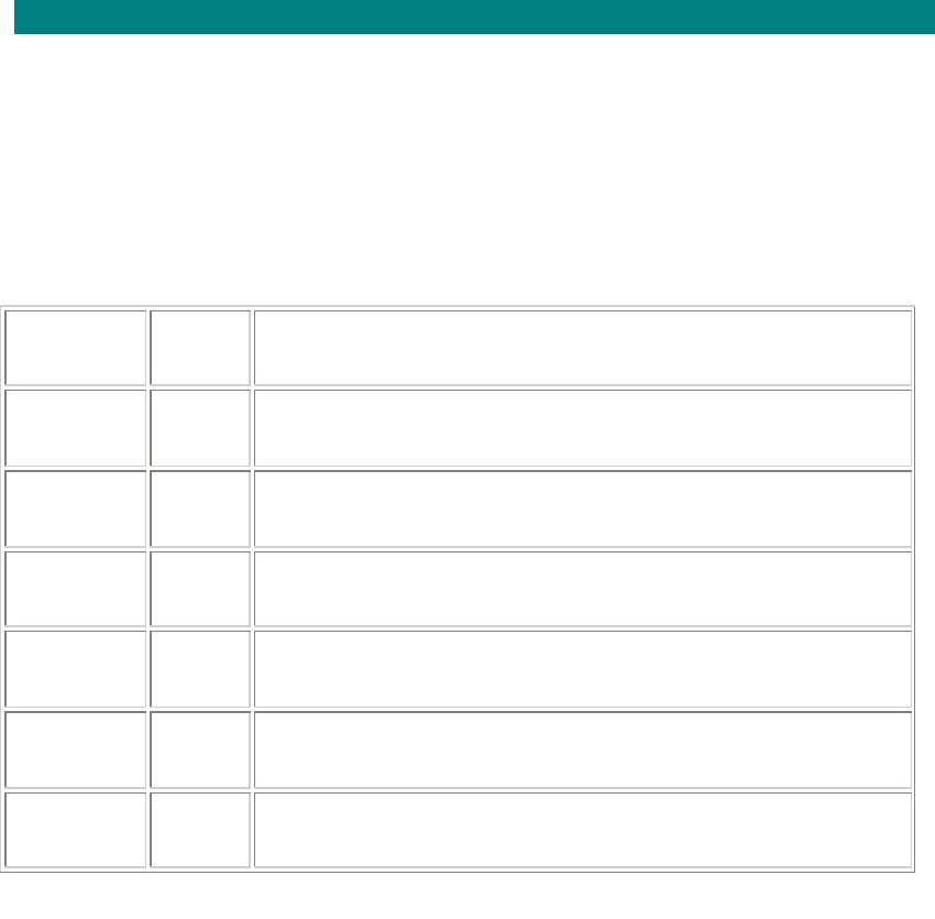
Type 42 subscriber terminals have the majority of the electronics in the Service Interface Unit
(SIU) located inside the customer premises. This is connected to the outdoor unit by an IF
drop cable. The ODU contains the RF components.
The iST subscriber terminal have the majority of the electronics in the Outdoor Unit (ODU)
and they are connected via a drop cable to the Indoor Unit (IDU) that contains the power
supply and the customer interfaces.
When an AS4020 system is planned, for overall RF capacity purposes an assumption will be
made of either the average modulation rate to be achieved across all subscribers or a specific
mix of modulation rates will be assumed across the subscribers. This introduces a new factor
into ST installation procedures: a check needs to be made of the actual modulation rate
achieved against the planned modulation. If this check is not carried out, the assumptions
made for modulation at the planning stage are not verified, with the potential result of the
achieved overall RF capacity being much less than the planned capacity, resulting in a
reduced level of service for subscribers.
In addition to establishing modulation rates for each subscriber, the RF Planning process will
ensure that adequate fade margins are present in order to achieve adequate link availability
figures. Fade margins are associated with two parameters – SNR and Receive (downlink)
/Transmit (uplink) Level. In an interference free, or island deployment, these two parameters
will be closely matched. However, in a deployment limited by interference levels (through
external interference or aggressive frequency reuse), The two parameters will be influenced
by different factors.
The output of an RF Planning exercise will generate the following requirements relating to an
individual ST deployment:
• Expected Modulation Modes (uplink & downlink) – based on the Rx SNR predicted
• Required SNR Margin above Modulation Mode switching threshold – to maintain
planned overall system throughput under shallow fade conditions.
Where average overall system throughput is a concern, a 0dB SNR Margin is considered
adequate for standard internet access services – this is because as some users SNR
degrades, others will improve maintaining an average system throughput. For a conservative
approach to system planning, a 2dB SNR margin would be adequate. However, if a particular
ST requires guaranteed high bandwidth for services such as video conferencing, then the
SNR margin would be increased.
The fade margin required to maintain link availability will depend on the actual availability
level required plus the propagation conditions. This is typically between 6 and 12dB.
Telephony
For normal telephony services, these could typically include:
• multi-frequency or loop-disconnect dialling
• subscriber private metering
• intrusion tone
• malicious call interception.
• caller line identification
Note. Line reversal is not supported.
All tones, tone cadences and announcements which are generated by the local exchange are
passed transparently over the AS4020 system. Line feed voltage, ringing current and ringing
cadence are generated by the ST equipment.
The Customer Premises Equipment (CPE) is connected to the line interface sockets on the
internal SIU.
605-0000-595 Subscriber Terminal Installation and Commissioning
24
The specific impedance of the NTU allows tests to be performed by the SIU to detect the
presence of any attached CPE.
Packet Data
Packet Data using 10/100baseT Ethernet links
The Type 42 P1 and iST offer an Ethernet service, which allows applications such as home
Internet access and Virtual Private Networks (VPN) for business users. It is designed to
operate with downlink speeds of up to 2Mbit/s and uplink up to 1Mbit/s, although the typical
configured uplink rates will depend on the number of STs on the system.
The system uses Ethernet bridging, which has the advantage of relaying frames based on
their MAC address, and so allows higher level protocols such as TCP/IP and IPX to pass
transparently across the system. In this manner, the system is easy to configure, and
provides a link that is transparent to devices on the LAN at each end of the bridge.
The system links Ethernets using self learning MAC bridging and supports the following
features:
• Ethernet IEEE 802.3 10baseT RJ45 connector
• Transparent Bridging allows the use of TCP/IP, IPX and other protocols over the link.
• Supports up to 480 P1V2 Subscriber Terminals per RF channel
• RF packet throughput capacity up to 8.5Mbit/s downstream, 5.7 Mbit/s upstream
IEEE 802.1q VLAN s
The 802.1Q standard (VLAN tagging) is also supported by the system, which is a secure
means of segmenting a network. The traffic between VLAN's is restricted, thereby providing
secure boundaries and limiting the propagation of broadcast and multicast traffic. This means
that any equipment supporting VLAN tagging will be able to connect to the Type 42 P1 , and
present each VLAN id on a separate Ethernet segment for connection into the appropriate
network.
IEEE 802.1q VLAN support on the AS4020 and Router provides security isolation is required
between these corporate customers by creating Corporate Virtual Private Networking and
allows independent LAN traffic to be carried over a single physical interface. 802.1q VLAN
adds an identifier to each ethernet packet to identify which VLAN it belongs to.
A router supporting 802.1q provides multiple VLAN subinterfaces (and IP addresses) on a
single physical Ethernet interface. VLAN security allows independent assignment (including
duplication) of IP addresses between VLAN groups.
VLAN security is used together to provide total security isolation of grouped Ethernets.
Ethernet linking is via MAC bridging providing protocol transparency. The user interface is
10baseT on RJ45 socket.
Overview of ST operation working on AS4020
Block Data Mode
BDM is used on the radio interface and transmits blocks of data using a connectionless
protocol
BDM transfers data across the air interface in discrete sized blocks. The payload for a given
destination may be contained within a single block (size permitting), or across multiple blocks.
The data field spreading factor, modulation and coding rate may be allocated by the system
on a per block basis to match the signal to noise ratio of the channel.
In the uplink an ST is allocated up to 4 RWs for voice and up to 4RWs for packet to transmit
on by the CT on a per slot basis.
The block duration is fixed throughout the system.

AS4020 STs
25
RW Codes
Each RF channel is composed of 16 RW codes: Each RW uses can de either 128kbit/s or 2 X
64kbit/s
RW code 15 is used for initial ST link acquisition and for downlink transmission of the internal
CTS channel which is used to signal to STs the availability of channels to use for uplink
transmissions. The remaining RW codes are used for voice and/or data. The voice/data
boundary is dynamic with RW codes only being used for voice when this is required due to
voice calls in progress. This maximises the data carrying capacity of the system as RWs not
being used for voice are automatically made available for data.
Each ST has a permanent always-on RTS/CTS channel. When an ST wishes to send uplink
traffic, it signals this on the RTS channel and receives in return a reply from the AS4020 CT
on the CTS channel informing the ST of which RW(s) can be used for the uplink voice/data
transmission. The AS4020 is thus able to arbitrate between RTS requests from all STs and
decide on a priority basis which STs are allowed to make an uplink transmission.
For the maximum ST load of 480 STs per AS4020,One or two RWs are reserved in the uplink
direction for RTS channels. Note that the downlink part of each of these RWs is free to carry
user data traffic. This means that a data only AS4020 application has 15 RWs available in the
downlink and 13 or 14RWs available in the uplink for user data. The carrying capacity in bit/s
will depend on the modulation type and FEC code used for transmission to each ST.
A voice only AS4020 application has 13 or 14 RWs free in both the uplink and downlink
directions for user voice calls.
AS4020 delivers data services to individual STs at various data rates depending on the
modulation and forward error correction (FEC) mode it is operating in. The mode used is
dependant on the RF link quality which is measured as a ratio of received signal strength to
noise level (signal to noise ratio – SNR). The higher the SNR, the higher the mode of
operation and hence, the higher the data rate to the ST. Various factors influence the level of
noise seen by the system. These include:
· Thermal (background and intra-system) Noise
· Interference (co and adjacent frequency channels)
· Excessive Multipath (signals received from reflections)
AS4020 dynamically adjusts its mode of operation on a per ST basis depending on a
continually updated measure of SNR. This measure of SNR includes all factors as listed
above.
605-0000-595 Subscriber Terminal Installation and Commissioning
26
AS4020 Subscriber Terminal Products
AS4020 Compatible Subscriber Terminal Types
There is a range of STs available, each supporting different services and numbers of lines.
The type 42 ST is compatible with Release 7.10 Netspan code or later and with Release 7.10
rack code or later.
The iST is compatible with release 7.21 or later
Subscriber
Terminal Type Function
P1/V2 Type
42 Two line voice 32kbit/s ADPCM or 64kbit/s PCM + 10BaseT
Ethernet
P1/V4 Type
42 Four line voice 32kbit/s ADPCM or 64kbit/s PCM . + 10BaseT
Ethernet
V2 Type
42 Two line voice 32kbit/s ADPCM or 64kbit/s PCM
V4 Type
42 Four line voice 32kbit/s ADPCM or 64kbit/s PCM .
W Type
42 Two line voice 32kbit/s ADPCM or 64kbit/s PCM + wireless LAN
interface uses IEEE 802.11b 10BaseT Ethernet
iST iST Two line voice 32kbit/s ADPCM or 64kbit/s PCM + wireless LAN
interface uses IEEE 802.11b 10BaseT Ethernet
AS4020 STs
27
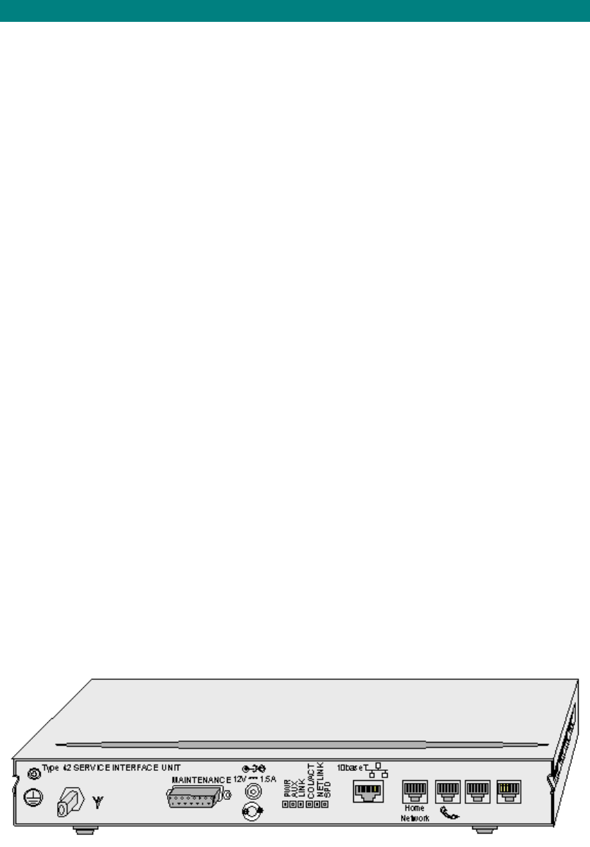
Type 42
Type 42 Overview
Type 42
• P series for packet data/voice
• V series for voice
The main elements comprise:
• External Outdoor Unit with antenna (ODU)
• Internal Service Interface Unit (SIU)
• IF drop cable
• Type 7 PSU (for STs requiring battery back-up) or Type 6 socket PSU (for STs not
requiring battery back-up)
Outdoor Unit
The outdoor unit is a sealed weatherproof unit that is mounted on the outside of the
customer’s premises. The unit is normally positioned on an outside wall or a mounting that
faces the direction of the CT antenna. The ST should be sited to avoid large obstructions in
proximity to and in line of sight from the ST to the CT antenna. See the ST installation and
commissioning manual for deployment rules.
The outdoor unit contains a flat plate antenna, Low Noise Amplifier (LNA) and Conversion of
incoming RF signal to IF. It connects to the IF drop cable using an F type connector. Power
for the LNA is provided via the drop cable.
605-0000-595 Subscriber Terminal Installation and Commissioning
28
The Outdoor Unit has two mounting options:
a) Pole Mount
b) Wall Mount
Pole Mounting
The antenna is normally pole mounted on a 38mm(1.5") Pole (provided by the service
provider). Adjustment of the antenna (in the azimuth plane) is achieved by rotating the
outdoor unit around the pole, the optimum positioning being determined by measuring the
strength of the incoming signal, usually in the direction of the CT antenna.
Wall Mounting Bracket
The outdoor unit mounting bracket fixes directly onto the wall of the building and provides
adjustment (in the azimuth plane) of the antenna in an arc over 150°, the optimum positioning
being determined by measuring the strength of the incoming signal, usually in the direction of
the CT antenna.
IF Drop Cable
The drop cable connects the internal SIU to the antenna via an environmentally protected F-
Type connector that is plugged into the backplate of the antenna. The drop cable come in
standard (RG6) or low loss (RG11). The IF drop cable is 50m(RG6) or 75m(RG11) with a
40mm maximum bend radius.
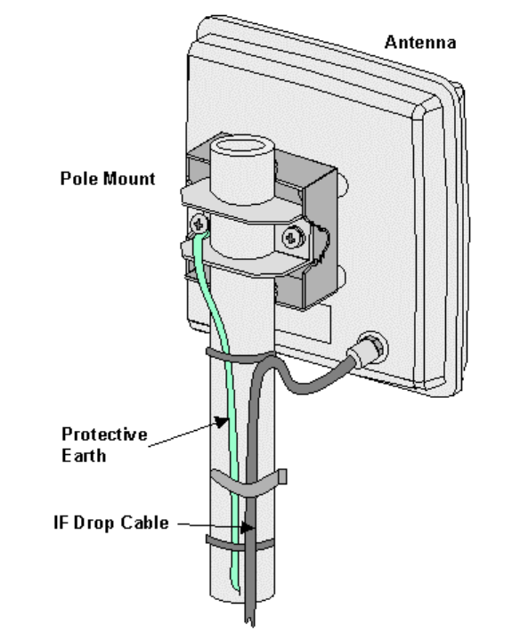
Power Supply Units
Two types of PSU are available. The Type 7 PSU for installations that require battery back-
up and the Type 6 PSU for installations that do not require battery back-up.
The, R, S, series SIUs use a Type 6 PSU
AS4020 STs
29
AC Power Supply Unit Type 6
The Type 6 is a socket PSU the plugs directly into the AC supply socket. It is supplied with a
range of adapters to ensure compatibility with the socket design in the country of deployment
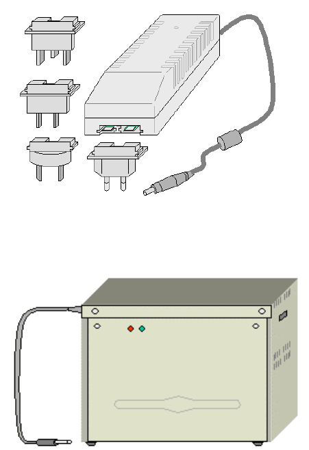
AC Power Supply Unit Type 7
The type 7 ST PSU cad be used to provide power to all SIUs and has a 7AH battery back-up
to maintain the functionality of the ST in the event of a mains supply failure. The PSU may be
free standing or wall mounted.
605-0000-595 Subscriber Terminal Installation and Commissioning
30
The P Series Subscriber Terminal
The P Series Service Interface Units (SIUs) are designed for packet data and use an outdoor
unit and an internal SIU. The STs are powered from the AC mains supply.
The PI/V2 is available in two versions the type 41 (not AS4020 compatible) and the type 42
that must be used for AS4020 Installations
The P1/V4 is only available in type 42.
ST- P1V2/4(type 42)
• P1/V2: Up to 2 voice calls - must share same RW code. Same
P1/V2: Up to 4 voice calls - must share same RW code.
• up to 4 RW codes per ST - voice independent uplinks.
• Ethernet (10 Mbit/s) 10 baseT - RJ45 connector
• Voice either 32k ADPCM or 64k PCM
• Analogue Fax/Modem supported as for normal voice signal - no additional hardware
required
• Phone - 2 RJ11 phone connectors
Downstream
• up to 4 RW codes per ST - shared between packet and voice
• Max 2Mbit/s downstream packet rate.
• When a voice line activates (one voice already active), packet downstream rate is
unaffected.
Upstream
• Upstream packet rate selectable up to 748kbit/s .
The ST Indoor Unit (IDU) is band/frequency independent. This allows changing IDU ST
operation frequency at any time by simple reprogramming using STMON or sometimes only
by changing parameters of target shelf with AS8200 .
Indoor Units
The ST-P1/V2 supports two 32kbit/s ADPCM or 64kbit/s PCM analogue telephony line and
one packet data line at the end-users premises. Provisioning is by the AS8200 management
system and AS7020 STMON. The type 42 PI/V2 is the same as the P1/V4 but two voice ports
are disabled.
The ST-P1/V4 supports four 32kbit/s ADPCM or 64kbit/s PCM analogue telephony line and
one packet data line at the end-users premises. Provisioning is by the AS8200 management
system and AS7020 STMON.
AS4020 STs
31
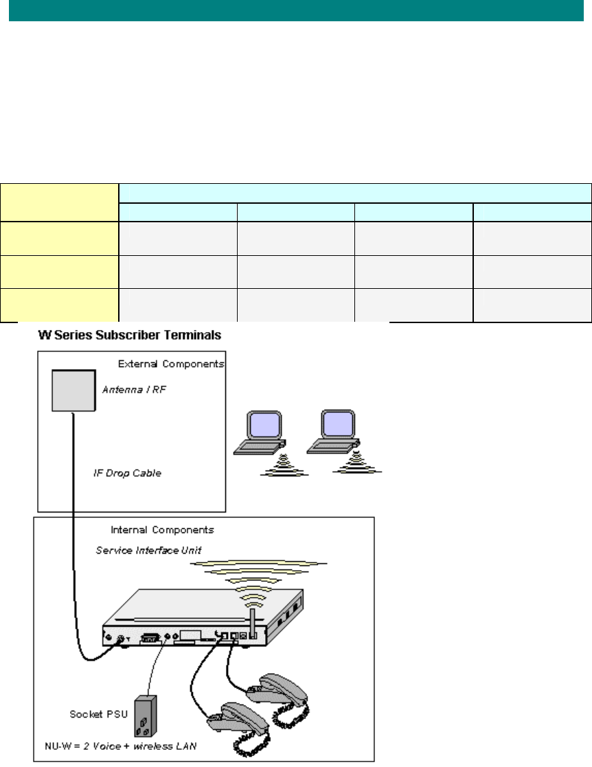
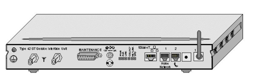
W Series
The ST W is designed for packet data and voice and use an outdoor unit and an internal
service interface unit with a wireless LAN antenna attached. The STs are powered from the
AC mains supply. The wireless LAN interface uses IEEE 802.11b Standard for high speed
wireless LANs.
Note: This SIU should not be installed in environments where the ambient temperature
is greater than 35° C
The range of the wireless LAN is dependant on the environment in which the unit is deployed.
In ideal conditions and the approximate range is shown in the table below. For increased
range the antenna provided with the unit may be disconnected and replaced with a high gain
antenna provided by the service provider.
Speed Environment
11 Mb/s 5.5 Mb/s 2 Mb/s 1 Mb/s
Open
Environment 160 m (525 ft.) 270 m (885 ft.) 400 m (1300ft.) 550 m (1750ft.)
Semi-open
Environment 50m(165ft.) 70m (230 ft.) 90m (300 ft.) 115m (375 ft.)
Closed
Environment 25 m(80 ft.) 35 m(115ft.) 40 m (130ft.) 50 m (165ft.)
ST –W (type 42)
The ST-W is AS4020 compatible and supports the following features:
• Phone - 2 RJ11 phone connectors
• Up to 2 voice calls - uses independent uplinks
• Voice either 32k ADPCM (max 2 channels) or 64k PCM (max 1 channel)
• Analogue Fax/Modem supported as for normal voice signal - no additional hardware
required
• up to 4 RW codes per ST
• 802.11b Wireless LAN data interface. This interface is set from the PC using at the
wireless LAN connection.
605-0000-595 Subscriber Terminal Installation and Commissioning
32
• The ST Indoor Unit (IDU) is band/frequency independent for the Radio Link. This
allows changing IDU ST operation frequency at any time by simple reprogramming
using STMON or sometimes only by changing parameters of target shelf with AS8100
[see Frequency Agility in AS8100 Sitespan help file].
AS4020 STs
33
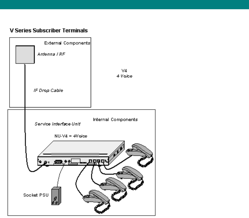
V Series
The V Series Service Interface Units are designed for Voice and use an outdoor unit and an
internal Service Interface Unit. The STs are powered from the AC mains supply.
ST –V2 (type 42)
The ST-V4 is AS4020 compatible and supports the following features:
• Phone - 2RJ11 phone connectors
• Up to 2 voice calls - uses independent uplinks
• Voice either 32k ADPCM (max 2 channels) or 64k PCM (max 1 channel)
• Analogue Fax/Modem supported as for normal voice signal - no additional hardware
required
• up to 2 RW codes per ST
• The ST Indoor Unit (IDU) is band/frequency independent. This allows changing IDU
ST operation frequency at any time by simple reprogramming using STMON or
sometimes only by changing parameters of target shelf with AS8100 [see Frequency
Agility in AS8100 Sitespan help file]. The type 42 ST is compatible with Release 7.0
Sitespan code and with Release 6.20 rack code or later.
• two voice ports and the 10baseT port is not enabled on this product.
ST –V4 (type 42)
The ST-V4 is AS4020 compatible and supports the following features:
• Phone - 4 RJ11 phone connectors
• Up to 4 voice calls - uses independent uplinks
• Voice either 32k ADPCM (max 2 channels) or 64k PCM (max 1 channel)
• Analogue Fax/Modem supported as for normal voice signal - no additional hardware
required
• up to 4 RW codes per ST
605-0000-595 Subscriber Terminal Installation and Commissioning
34
• The ST Indoor Unit (IDU) is band/frequency independent. This allows changing IDU
ST operation frequency at any time by simple reprogramming using STMON or
sometimes only by changing parameters of target shelf with AS8100 [see Frequency
Agility in AS8100 Sitespan help file].
• The 10baseT port is not enabled on this product

AS4020 STs
35
Specifications
Outdoor Unit
Size: Outdoor Unit without brackets: 210mm W x 210mm H x 80mm D
Weight: Outdoor Unit without brackets: 1.10kg
Operating Temperature: -40°C to +65°C
Relative Humidity: 0 to 100% non - condensing
Storage Temperature:-30°to 70°C
Wind Gusts:200 km/hr
Ice Accumulation of Density: 900 kg/m: 10mm (complete equip. coverage)
Indoor Units
P Series Service Interface Unit
Size: 323mm x 180mm x 40mm
Weight 1.53kg
Operating temperature -5 °C to +45°C
V Series Service Interface Unit
Size: 200mm x 180mm x 60mm
Weight 2.25kg with battery
Operating temperature -5°C to +45°C
W Series Service Interface Unit
Size: 200mm x 180mm x 60mm
Weight 2.3kg with battery
Operating temperature -5°C to +35°C
Power Supply Unit Type 6
AC Input Voltage: Range, 100VAC to 240VAC.
Frequency: 47 to 63 Hz.
AC Input: 0.7 Amp.
Nominal Output Voltage: 12V DC
Power Consumption: 15 Watts
Overload Protection Fuse: 2.0 Amp.
Power Supply Unit Type 7
AC input Voltage: Range, 100VAC to 240VAC. (+6% -10%)
Frequency: 45 to 65 Hz.
AC Input: 1 Amp.
Nominal Output Voltage: 13V DC ±1V
Output 2.0Amp Max
Overload Protection Fuse: 2.0 Amp.
Power Consumption: 15 Watts
Insulation: Class II
Battery TBA
Operating Temperature: -5°C to +45°C

37
Installation
Pre-installation
Before the ST is installed, the installation acceptance criteria should be established. These
are outputs from RF Planning as listed above. They are in summary:
o Corresponding STID
o RF Channel/Pilot Channel
o PN Code
o Expected Downlink Modulation (FEC Mode)
o Expected Uplink Modulation (FEC Mode)
o Required Fade Margin
o Required Downlink SNR
These parameters can be input to STMon during installation. It is expected that the installer
will be informed of these values via a job instruction relating to the particular ST to be
installed.
605-0000-595 Subscriber Terminal Installation and Commissioning
38
Installation Steps
Before commencing installation read the section 'Preparation' to familiarize oneself with the
deployment guidelines etc.
All types except iST
Step Activity Notes
1 Provision
ST in
AS8200
STID, MAC Address & ST Service class details are to
be entered into Netspan before the installation can
commence. See Netspan User guide
2
Configure
ST IDU AS4000 only STID, RF Channel & PN Code to be
programmed.
Telephone handset programming will be available
with 7.21.
Step Activity Mounting Notes
3
Installing
Outdoor
Unit
(ODU)
Bracket
605-
0010-
279/280
Bracket
605-
0010-
283
Pole
Mount IF Unit IF unit only
required if
non Airspan
Antenna is
used.
Step Activity Termination Notes
4 Install Drop
Cable Drop Cable Installation
5
Drop Cable
Termination RG6
Snap
and
Seal
RG11
Snap
and
seal
RG6
Crimp
RG11
Crimp ST
Installation
Toolkit 605-
0010-313
used for
Snap and
Seal
connectors.
ST
Installation
Toolkit 605-
0010-257 for
crimp
connectors
Step Activity Type Notes
6 Install
PSU Type
6
PSU
Type
7
PSU
Step Activity Series AS4000 AS4020 Notes
B Installing B Series
SIU ISDN
L Installing L Series
SIU DATA
M Installing M Series
Module Enclosure Modular
N Installing N Series
SIU Voice
7 Install
Service
Interface
Unit
(SIU)
P Installing P Series
SIU Installing P
Series SIU Packet/voice
Installation
39
R Installing R Series
SIU (RU-V1/V2) Voice
S Installing S Series
SIU Voice
V Installing V series
SIU Installing V
series SIUs Voice
W Installing W series
SIU Installing W
series SIU Wireless
CPE
connection

605-0000-595 Subscriber Terminal Installation and Commissioning
40
Preparation
Site Selection
Site Readiness
Verifying that the site is ready for the installation of the ST equipment.
Check access to the building before unloading or unpacking the equipment.
Outdoor Unit Important Installation Considerations
Geographical deployment within guidelines: Just because a ST seems to get a link on an
excessively long distance or on a side lobe to a sectored antenna, this doesn’t mean it will
work reliably. Frequency (Radio) planning is essential for the area covered (including
frequency sweep to identify possible interferers).
Clear line of sight: This is the single most likely reason for an installation not to work. Check
for: • Any buildings or large trees, especially ones close to the ST, which obscure
the line of sight will significantly reduce the RF power, and could cause
problems with reflections. Trees should be at least 50m from ST installation
RF path. Although AS4020 can operate through trees,absorption losses for a
single tree can increase the path loss 6-9dB and foliage movement due to
wind can cause varying path losses degrading BER performance. Note:
Trees exceeding a distance of 50 metres from the antenna are considered
ineffective to the units' performance.
• Place the outdoor unit as high as possible to avoid local clutter caused by
people/vehicles/trees. Make sure the outdoor unit is actually pointed at the
CT. Mounting height should normally be 5-7 metres above ground level.
• Ensure that the antenna path has sufficient near field clearance (see 'Site
Selection' below)
• No other radio broadcasting units are likely to transmit across or into the
antenna boresight and have a separation from Airspan equipment of at least
2m.
• For efficient and reliable service it is suggested that the external mounting
location of the outdoor unit be chosen such that once 'panned' for optimum
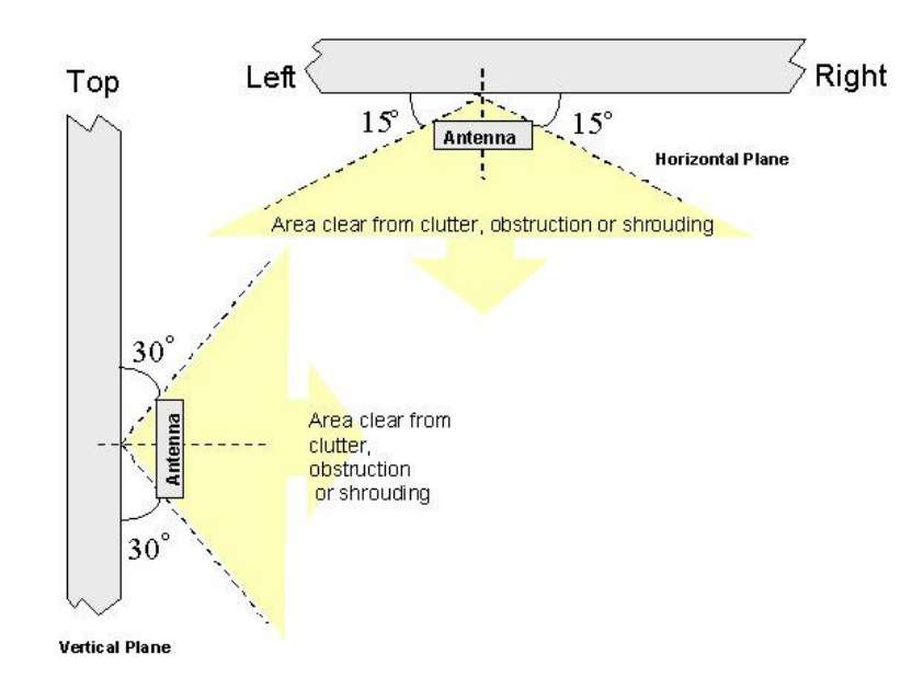
signal level it observes the following criteria:-
• Avoid obstructions such as adjacent walls or overhanging roof eaves,
within 15° in the horizontal plane and 30° in the vertical plane (see
figure below).
• Ensure adequate clearance is allowed for 'panning' the outdoor unit.
• The antenna is capable of being 'panned' with at least 15° of
adjustment either side of the direction of the CT antenna.
These guidelines should not be violated during the outdoor unit panning
process.
Physical separation: STs at the same location must have at least 1 metre separation
between their outdoor units, to stop coupling between them causing interference.
Correct orientation: The ST outdoor unit has a required orientation, mounting it at 90 degrees
to this (e.g. by attaching it to a horizontal rather than vertical mounting bar) will affect the RF
performance.
Installation
41
Before installing an outdoor unit a test ST should be used to check that the ST has sufficient
fade margin and is able to deliver the target quality of service. The test outdoor unit is usually
mounted on a telescopic pole and powered from a vehicle battery a drop cable connects to
the SIU and the outdoor unit is pointed in the direction of the CT .Place the outdoor unit up
against the building at the position where the outdoor unit is to be fixed and slowly pan the
outdoor unit though the path of the CT until a signal is received. Check that the ST can
acquire a link and that a make a test call over the system.
Check for both way transmission and absence of noise and interference. If there are any
problems with the reception and quality of the call then reposition the outdoor unit and repeat
the process until a viable location is found.
Outdoor Unit Positioning
The mounting should be solid and firm, and the outdoor unit placed in a position where
objects will not move in front of it, e.g. seasonal variations for trees (leaves, snow covering,
growth), people walking across roofs, tall vehicles driving past, a new building being
constructed in the line of sight, etc.
Inspect the suitability of the wall structure for the installation position of the outdoor unit
mounting.
Typical acceptable structures are:-
• Secure brick walls
• Concrete cladding covered building blocks
• Metal / wooden pole, with suitable bracket.
Check how the drop cable is to enter the site and the internal drop cable run from the antenna
to the internal SIU.
Before commencing with the installation, confirm with the customer the following:-
• Suitability of the outdoor unit position.
• Entry point of the drop cable to the site. Keep the drop cable short: As the I/F
frequencies are attenuated by the drop cable, any significant unused length should be
cut off before termination. Also, use low loss drop cable for potentially marginal
installations.
• Internal cable run from entry point to the SIU.
605-0000-595 Subscriber Terminal Installation and Commissioning
42
ST W 802.11b Wireless Antenna Positioning
To maximize the wireless coverage, place the unit as centrally as possible (depending
on the wireless computer's vicinity)
Power Availability
Check with the customer the suitability of the SIU position - Within 1 metre of the AC power
outlet and within 50/75 metres of the antenna (lengths of drop cable are 50 metres or 75
metres). Ensure a good power supply for the ST: Do not connected to intermittent supplies ,
e.g. central heating timers. This will shorten the battery life (if fitted) considerably as it is not
designed to be constantly charged and discharged.

Installation
43
Unpacking and Inspection
Important: Check Configuration
Ensure correct software build and configuration: Check this before leaving ‘base’ as it may be
time consuming or not be possible to remedy this at the customer’s site.
2. Delivery Inspection
Upon taking delivery of the equipment consignment, check that the consignment agrees in all
particulars with the consignment delivery documentation (number of boxes, descriptions,
contents of boxes, etc.). Any discrepancy or damage must be reported immediately to Airspan
(+44 (0) 1895 467 467 ) for further instructions. In case of severe damage, do not accept the
consignment from the carrier.
3. Unpacking Inspection
The contents of each box must be checked against the relevant part lists provided with the
box, for the correct part numbers and quantities, and for damage. Any shortage or damaged
items must be reported immediately to Airspan for further instructions at the address given
below :
Airspan Communications Limited
Cambridge House
Oxford Rd
Uxbridge
Middlesex
UB8 1UN
Int. Tel: +44 (0) 1895 467 467 Int. Fax: +44 (0) 1895 467 472
Dispose of all unnecessary packaging in a safe manner according to the customer's
requirements.
Note: It is recommended that one package carton of each type be retained should it be
required to return any faulty or damaged items for repair.

605-0000-595 Subscriber Terminal Installation and Commissioning
44
Required Tools and equipment.
1. Required Tools
The following lists of tools and equipment are required to successfully install and test the
Subscriber Terminal (ST) equipment.
General Tools
DESCRIPTION MODEL SIZE/Part No
Combination
Spanner 13mm
Ratchet and Socket 17mm
Spirit Level 18 inch
Screwdriver Pozidrive No 1 x 75mm
Screwdriver Pozidrive No 2 x
199mm
Screwdriver Pozidrive No 3 x
150mm
Screwdriver Flat Blade 3mm x
100mm
Hammer Ball Pein 1lb
Drill/driver Cordless – with depth
gauge Hilti
Drill Bit Masonry 6mm
Drill Bit Masonry 10mm
Ladder – Triple Fully Extended 7 metre minimum
RG 6 Snap and Seal
Crimp Tool 166-8000-027
RG11 Snap and Seal
Crimp Tool 166-8000-030
Stripping Tool RG6 166-8000-028
Torque Wrench RG6 166-8000-021
Torque Wrench RG11 166-8000-033
Large side Cutters 166-8000-023
Screwdriver Pozi PH3 166-8000-018
ST Installation
Toolkit 605-0010-
313 used for Snap
and Seal
Connectors
consisting of a
Toolbox with the
following Items:
Laminated Instruction
Sheet 166-8000-031
RG 6 Round Crimp Tool 166-8000-020
RG11 Hexagonal Crimp
Tool 166-8000-019
Fixed Torque Wrench 166-8000-021
Screwdriver Pozi PH3 166-8000-018
Retractable Trimming
Knife 166-8000-022
Large side Cutters 166-8000-023
12" Steel Ruler 166-8000-024
Laminated Instruction
Sheet (RG6) 166-8000-025
ST Installation
Toolkit 605-0010-
257 consisting of a
Toolbox with the
following Items:
Laminated Instruction
Sheet (RG11) 166-8000-026
Required Equipment
The table below shows the required equipment.
Installation
45
ITEM DESCRIPTION MODEL
01 Digital Multimeter Fluke 77 or similar
02 Test Telephone *Note 1
03 Compass
04 optional STmeter
05 optional STMON
Note 1: The system needs to be connected to a network switch to fully commission the STs.
Installers may not be familiar with the local environment and topographical conditions, it is
necessary to provide each installer with a map of the local area. A compass for use when
determining the exact bearing of the CT location is also necessary.
Optional Equipment
The table below shows the optional equipment.
ITEM DESCRIPTION MODEL
optional STmeter Airspan Proprietary
optional STMON Airspan Proprietary
605-0000-595 Subscriber Terminal Installation and Commissioning
46
Installing Outdoor Unit
Installing the Wall Mount Outdoor Unit Using Bracket 605-
0010-279/280.
Use this procedure to install the Outdoor Unit. Before installing the Outdoor Unit check that
the proposed position meets the site selection guidelines.
Country Specific Requirements
USA: In the USA the Outdoor Unit shall be installed in accordance with articles 725, 800, 810
and 820 of the National Electrical Code
Canada: In Canada the Outdoor Unit shall be installed in accordance with section 54 of the
Canadian Electrical Code
The Wall Mounting Kit comprises:
Item Quantity Use
Wall mounting Bracket 1 Fixed to Building
Wall Mounting Arm for T6 cable 1 Fixed to Outdoor Unit
or Wall Mounting Arm for T11
low loss cable 1 Fixed to Outdoor Unit
M8 x 20mm Bolts 2
M8 Coiled Washer 2
M8 Plain Washer 2
Pivot connecting Arm and
Bracket
M8 x 50mm Coach Bolt 4
M8 Plain Washer 4
Fixing to wood
M6 Dyna Bolt 4 Fixing to brick/block
M6 x 16mm Bolts 4
M6 Coiled Washer 4
M6 Plain Washer 4
Mounting Outdoor Unit to
arm
Cable Tie 3 Securing IF Drop Cable
Outdoor Unit Positioning and Securing.
STEP PROCEDURE
1. Confirm the position of the outdoor unit ensuring that there is no obstruction in front
and to either side.
Installation
47
2. When multiple STs are deployed at the same site the recommended minimum
spacing between each outdoor unit is 1 metre.
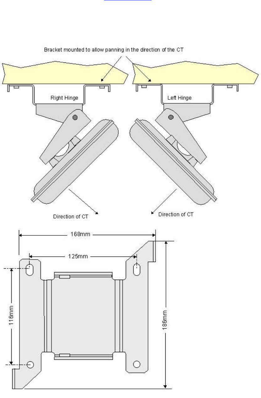
3. The Outdoor Unit mounting bracket should be fixed so that panning can take place in
the horizontal plane (i.e. pivots top and bottom). Check that line of sight with CT
antenna does not breach the deployment rules.
4. Note: Leave adequate clearance around the outdoor unit wall mounting assembly to
allow for the full adjustment range when aligning the antenna.
5. Locate the direction of the CT site using the survey information and decide if the
outdoor unit is to hinge from the left or right to allow panning in the directions of the
CT antenna. The same bracket is used for left or right hinge, Rotate the bracket to
give the required orientation.
Outdoor Unit Bracket Orientation
605-0000-595 Subscriber Terminal Installation and Commissioning
48
Outdoor Unit Wall Bracket Positioning and Securing
Securing Outdoor Unit Wall Bracket to wooden structure
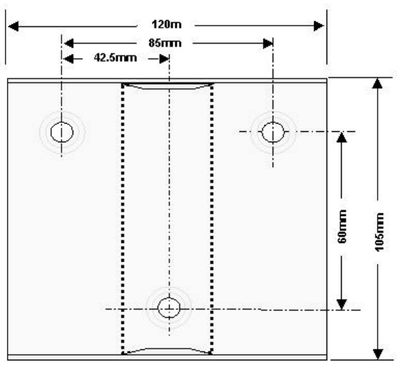
1. Using the wall bracket as a template, mark the first hole position.
2. Drill a first hole pilot, 5mm diameter to a depth of 15mm (use a drilling depth gauge),
place the mounting bracket on the wall with the pivot hinge set for correct panning.
Screw the M8 coach bolt provided through the mounting bracket into the hole.
Tighten sufficiently to secure the bracket to the wall.
3. Using a spirit level, adjust the position of the wall bracket and mark the remaining 3
holes.
4. Drill the remaining pilot holes, 5mm diameter to a depth of 15mm, then fit the hex
head M8 coach bolts provided through the mounting bracket into the holes.
5. Tighten all the bolts sufficient to ensure a firm fixing to the wall.
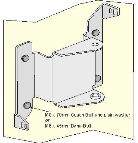
Securing Outdoor Unit Wall Bracket to brick/block structure
1. Using the wall bracket as a template, mark the first hole position. Where the Outdoor
Unit is to be mounted to a brick built building, try to ensure that each hole coincides
with the middle of a brick and not the mortar course.
2. Drill the first hole, 8mm diameter to a depth of 45mm (use a drilling depth gauge),
place the mounting bracket on the wall and then fit the hex head M6 Dyna Bolt
provided through the mounting bracket into the hole. Tighten sufficiently to secure the
bracket to the wall.
3. Using a spirit level, adjust the position of the wall bracket and mark the remaining
three holes.
4. Drill the remaining holes, 8mm diameter to a depth of 45mm, then fit the hex head M6
Dyna Bolt provided through the mounting bracket into the hole.
5. Tighten all the bolts sufficient to ensure a firm fixing to the wall.
Fixed wall mounting bracket
1. Assembling arm and bracket
Installation
49
2. If the outdoor unit is to be fed with the T10 low loss cable it is necessary to fit wall
extended mounting arm part to accommodate the larger bend radius of the cable.
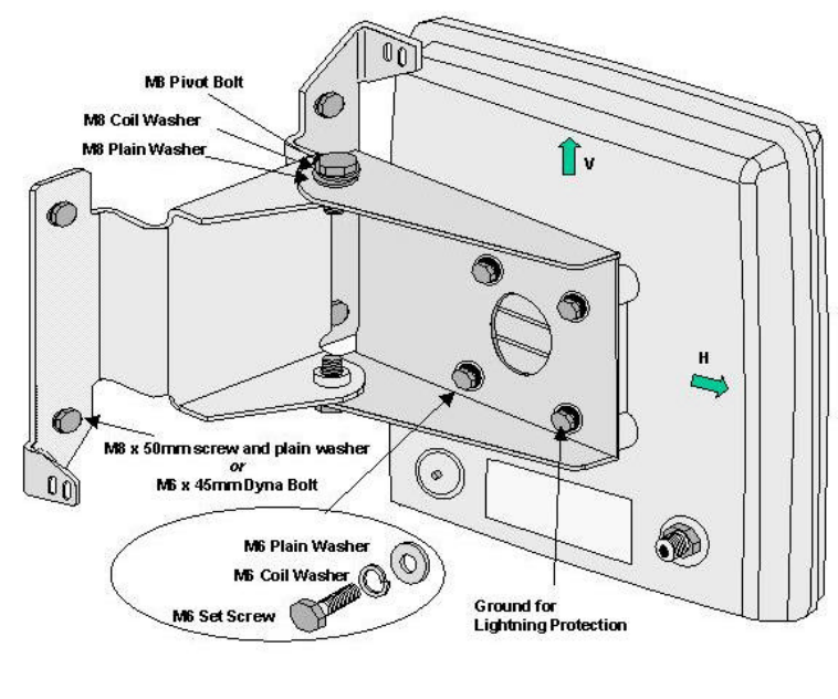
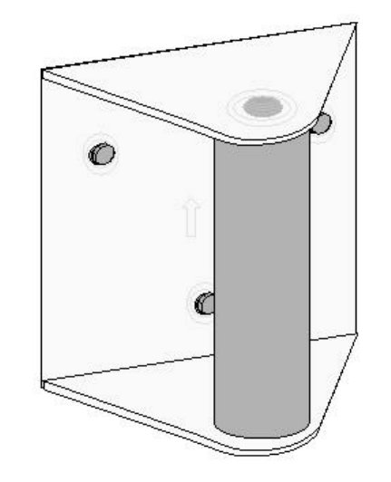
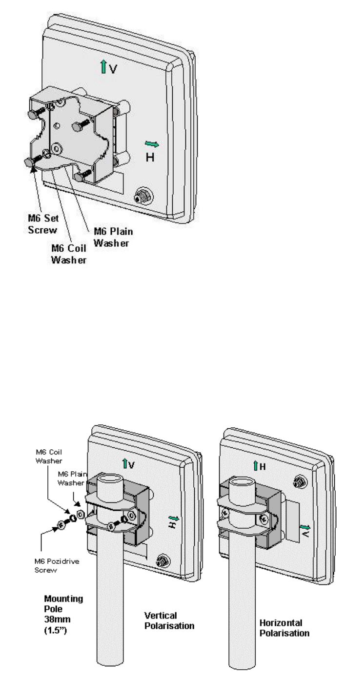
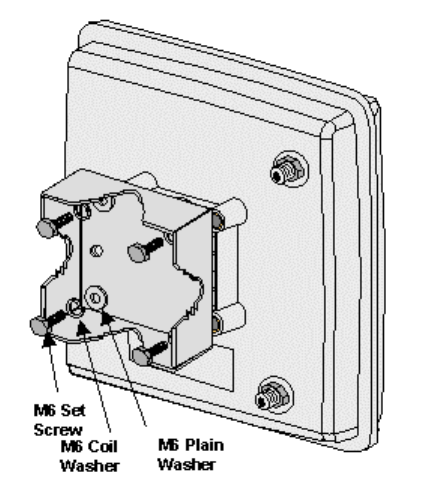
3. The outdoor unit should be fitted to the mounting arm. The orientation of the antenna
is dependant on the polorisation of the signal. The figure below shows the outdoor
unit mounted in the normal position (vertically polarised).The V marked on the
outdoor unit should be pointed up. The V is marked on both sides of the outdoor unit
to facilitate for left or right pivots on the bracket.
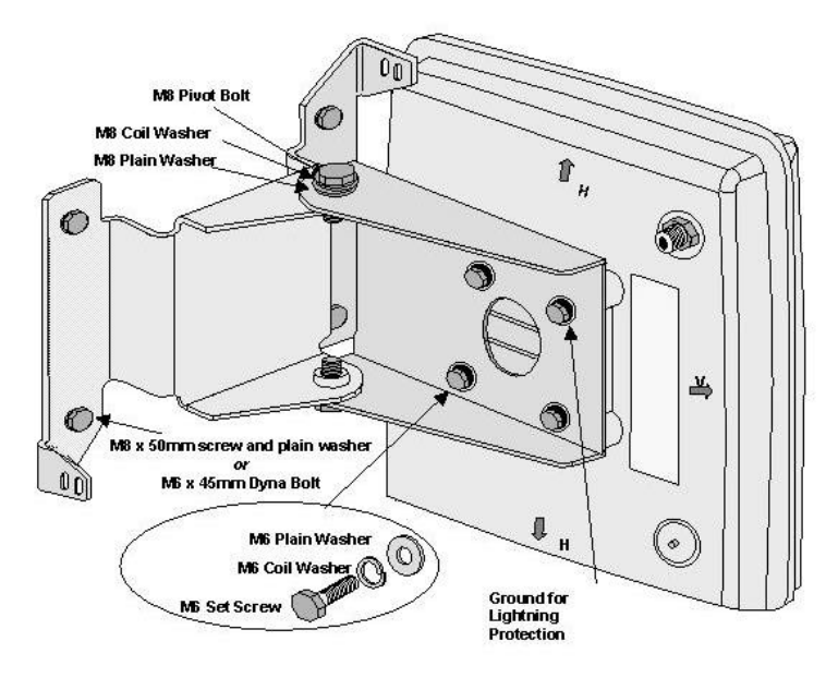
4. If the CT Antenna is horizontally polarised then the outdoor unit is rotated through 90
and mounted as shown in the figure below with the H mark pointed up. . The H is
marked on both sides of the outdoor unitto facilitate for left or right pivots on the
bracket.
Wall Mounted Outdoor Unit Vertical polarisation
5. If the CT antenna is horizontally polarised then the outdoor unit is rotated through 90
and mounted with the H mark pointed up. . The H is marked on both sides of the
outdoor unit to facilitate for left or right pivots on the bracket as shown in the figure
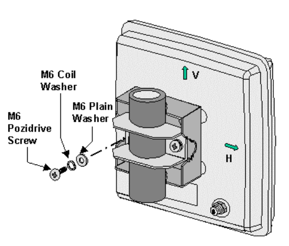
below. Secure the outdoor unit radium to the outdoor unit mounting bracket using four
M6*20mm hex head set screws, 6mm flat and 6mm coiled washers as shown in the
relevant figure mentioned above. Tighten the set screws to a torque of 1.75Nm.
605-0000-595 Subscriber Terminal Installation and Commissioning
50
Wall Mounted Outdoor Unit horizontal polarisation
6. Join the two halves of the bracket together using a bolt, spring washer, and plain
washer to top and bottom pivots.
7. Rotate the outdoor unit to face in the general direction of the CT. At this stage, only
finger tighten the pivot bolts.
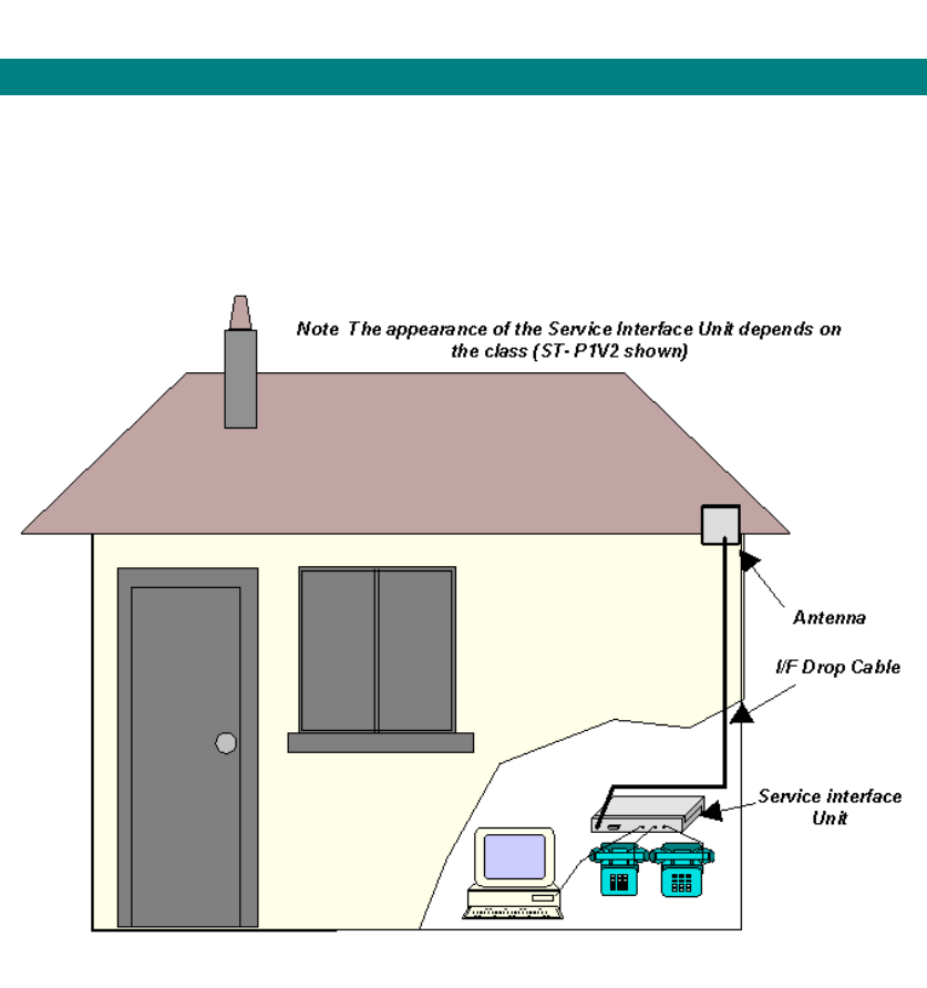
Lightning Protection
1. When the outdoor unit is attached to two / three floor dwellings lightning protection
should not be needed. If the outdoor unit is situated in an exposed position i.e on the
top of a multi-storey building the outdoor unit should be grounded.
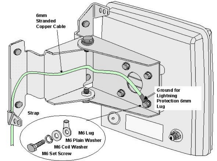
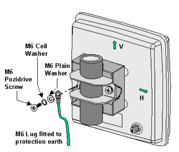
2. Run a stranded copper cable from the outdoor unit to a protection earth point i.e
building earth halo or earth provided specifically for lightning protection. The earth
connection from the antenna shall be a minimum of 10 AWG (6 mm2) copper wire in
accordance with UL 96 and 96A. The antenna drop cable shall be run separately from
the earth cable and any cables carrying hazardous voltages.
3. Secure the cable to the pole using straps and cleats as required
4. Fit a 6mm lug to the cable at the antenna end. Attach to the pole mount bracket using
the lower right M6 set screw as shown in figure below.
Installation
51
Lightning Protection for Exposed Bracket Mounted Outdoor Unit
5. Connect to the earth point in accordance with local practice.
If the above steps are followed any lightning strike on the antenna mounting bracket should
be discharged safely to earth. Direct strikes on the outdoor unit may cause damage to the
internal components of the antenna and it is also possible that the charge may damage
components in the SIU. The addition of a master socket fitted with discharge tubes should
protect internal wiring and customers premise equipment from damage.

605-0000-595 Subscriber Terminal Installation and Commissioning
52
Installing the Outdoor Unit Using Bracket 605-0010-283
Use this procedure to install the outdoor unit. Before installing the 0utdoor Unit check that the
proposed position meets the site selection guidelines.
Country Specific Requirements
USA: In the USA the outdoor unit shall be installed in accordance with articles 725,
800, 810 and 820 of the National Electrical Code
Canada: In Canada the outdoor unit shall be installed in accordance with section 54 of
the Canadian Electrical Code
The Wall Mounting Kit comprises:
Item Quantity Use
Wall
mounting
Bracket
1 Fixed to
Building
M8 x 50mm
Coach Bolt 4 Fixing to
wood
M8 Plain
Washer 4
M6 Dyna
Bolt 4 Fixing to
brick/block
Cable Tie 3 Securing IF
Drop Cable
Outdoor Unit Positioning and Securing.
STEP PROCEDURE
1. Confirm the position of the outdoor unit ensuring that there is no obstruction in front
and to either side.
2. When multiple STs are deployed at the same site the recommended minimum
spacing between each outdoor unit is 1 metre.
3. The outdoor unit mounting bracket should be fixed so that panning can take place in
the horizontal plane (i.e. pole vertical). Check that line of sight with the Central
Terminal (CT) antenna does not breach the deployment rules.
4. Note: Leave adequate clearance around the outdoor unit wall mounting assembly to
allow for the full adjustment range when aligning the outdoor unit with the CT.
Installation
53
Antenna Wall Bracket Positioning and Securing
Securing Antenna Wall Bracket to a Wooden Structure
1. Remove mini pole from bracket by unscrewing and removing the locating bolt and
pulling the pole clear of the bracket. The pole snaps onto the bracket and some force is
required to remove it.
2. Using the wall bracket as a template, mark the first hole position.
3. Drill a first hole pilot, 5mm diameter to a depth of 15mm (use a drilling depth gauge),
place the mounting bracket on the wall with the arrow embossed on the back plate
pointing up. Screw the M8 coach bolt provided through the mounting bracket and
screw into the hole. Tighten sufficiently to secure the bracket to the wall.
4. Using a spirit level, adjust the position of the wall bracket and mark the remaining 3
holes.
5. Drill the remaining pilot holes, 5mm diameter to a depth of 15mm, then fit the hex
head M8 coach bolts provided through the mounting bracket into the holes.
6. Tighten all the bolts sufficient to ensure a firm fixing to the wall.
605-0000-595 Subscriber Terminal Installation and Commissioning
54
Securing Outdoor Unit Wall Bracket to brick/block structure
1. Remove mini pole from bracket by unscrewing and removing the locating bolt and
pulling the pole clear of the bracket. The pole snaps onto the bracket and some force is
required to remove it.
2. Using the wall bracket as a template, mark the first hole position. Where the outdoor
unit is to be mounted to a brick built building, try to ensure that each hole coincides
with the middle of a brick and not the mortar course.
3. Drill the first hole, 8mm diameter to a depth of 45mm (use a drilling depth gauge),
place the mounting bracket on the wall and then fit the hex head M6 Dyna Bolt
provided through the mounting bracket into the hole. Tighten sufficiently to secure the
bracket to the wall.
4. Using a spirit level, adjust the position of the wall bracket and mark the remaining
three holes.
5. Drill the remaining holes, 8mm diameter to a depth of 45mm, then fit the hex head
M6 Dyna Bolt provided through the mounting bracket into the hole.
6. Tighten all the bolts sufficient to ensure a firm fixing to the wall.
Attaching Antenna to Stub Pole
1. The outdoor unit should be fitted to the mounting pole. The orientation of the outdoor
unit is dependant on the polorisation of the signal The figure below shows the outdoor
unit mounted in the normal position (vertically polarised). The V marked on the outdoor
unit should be pointed up. The V is marked on the top and bottom of the outdoor unit.
The polarisation must agree with that of the CT or the ST cannot receive a signal.
2. If the CT Antenna is horizontally polarised then the outdoor unit is rotated through 90
and mounted as shown in the figure below with the H mark pointed up. The H is
marked on the top and bottom of the outdoor unit.
Installation
55
Mounting Outdoor Unit (vertical polarisation)
3. Attach the pole to the bracket as shown in the illustration above. Fully tighten onto
the pole.
4. Fix the pole to the bracket. The pole snaps into place and the bracket may need
easing slightly to allow the pole to pass over the raised dome, Place the coach bolt
through the bracket from the top so that the square shank locates into the square hole
in the bracket.
5. Rotate the outdoor unit to face in the general direction of the CT. Place the washer
faced self locking nut onto the bolt and tighten sufficiently to secure the pole in place.
The nut will be finally tightened when panning at the commissioning stage
Lightning Protection
1. When the outdoor unit is attached to two / three floor dwellings lightning protection
should not be needed. If the outdoor unit is situated in an exposed position i.e on the
top of a multi-storey building the outdoor unit should be grounded.
2. Run a stranded copper cable from the antenna to a protection earth point i.e building
earth halo or earth provided specifically for lightning protection. The earth connection
from the outdoor unit shall be a minimum of 10 AWG (6 mm2) copper wire in
accordance with UL 96 and 96A. The outdoor unit drop cable shall be run separately
from the earth cable and any cables carrying hazardous voltages.
3. Secure the cable to the pole using straps and cleats as required
4. Fit a 6mm lug to the cable at the antenna end. Attach to the pole mount bracket
using the lower right M6 set screw as shown in figure below.
605-0000-595 Subscriber Terminal Installation and Commissioning
56
Lightning Protection for Exposed Bracket Mounted Outdoor Unit
5. Connect to the earth point in accordance with local practice.
If the above steps are followed any lightning strike on the outdoor unit mounting bracket
should be discharged safely to earth. Direct strikes on the antenna may cause damage to the
internal components of the outdoor unit and it is also possible that the charge may damage
components in the SIU. The addition of a master socket fitted with discharge tubes should
protect internal wiring and customers premise equipment from damage.
Installation
57
Installing The Pole Mount Outdoor Unit .
Use this procedure to install the outdoor unit. The mounting pole is not an Airspan supplied
item and the pole should be manufactured to suit local requirements. Before installing the
outdoor unit check that the proposed position meets the site selection guidelines.
Country Specific Requirements
USA: In the USA the outdoor unit shall be installed in accordance with articles 725, 800, 810
and 820 of the National Electrical Code
Canada: In Canada the outdoor unit shall be installed in accordance with section 54 of the
Canadian Electrical Code
The Pole Mounting Kit comprises:
Item Quantity
Ooutdoor Unit Bracket 1
Pole Bracket 1
M6 x 50mm Bolts or M6 x 60mm Bolts 4
M6 Coiled Washer 4
M6 Plain Washer 4
Cable Tie 3
Outdoor Unit Positioning and Securing .
STEP PROCEDURE
1. Confirm the position of the outdoor unit ensuring that there is no obstruction in front
and to either side.
2. When multiple STs are deployed at the same site the recommended minimum
spacing between each outdoor unit is 1 metre.
3. The outdoor unit mounting pole should be fixed so that outdoor unit panning can take
place in the horizontal plane and check that line of sight with CT antenna does not
breach the deployment rules. The outdoor unit mounting pole is locally provided and
should be 38mm or 1.5" in diameter. The pole should be fixed according to the pole
manufacturers’ instructions.
Note: Leave adequate clearance around the outdoor unit assembly to allow for the
full adjustment range when aligning the outdoor unit.
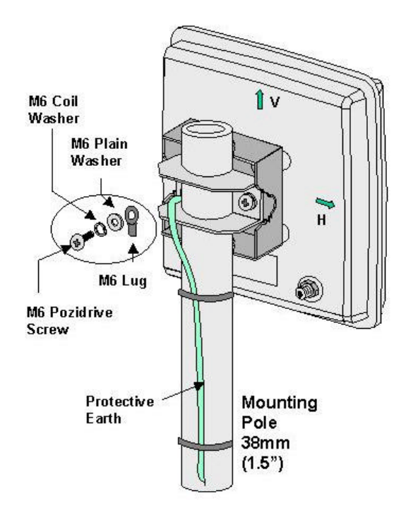
4. Secure the outdoor unit radium to the mounting pole bracket using the four M6*50mm
hex head set screws, 6mm flat, and 6mm coiled washers as shown below. Some
outdoor units have the bracket factory fitted.
605-0000-595 Subscriber Terminal Installation and Commissioning
58
5. For poles 32-38mm secure the antenna radium to the mounting pole using the clamp
bracket secured by two M6*50mm Pozidrive screws, 6mm flat, and 6mm coiled
washers as shown below. Tighten the set screws to a torque of 1.75Nm.
For poles 38-45mm secure the antenna radium to the mounting pole using the clamp
bracket secured by two M6*60mm Pozidrive screws, 6mm flat, and 6mm coiled
washers as shown below. Tighten the set screws to a torque of 1.75Nm.
Vertical Polarisation
The V marked on the outdoor unit should be pointed up. The V is marked on both
sides of the outdoor unit to facilitate for left or right cable entry.
Horizontal Polarisation
The H marked on the outdoor unit should be pointed up. The V is marked on both
sides of the outdoor unit to facilitate for top or bottom entry
.
Installation
59
6. Rotate the outdoor unit to face in the general direction of the CT. At this stage, only
tighten the pivot bolts sufficient to stop the outdoor unit sliding down the pole.
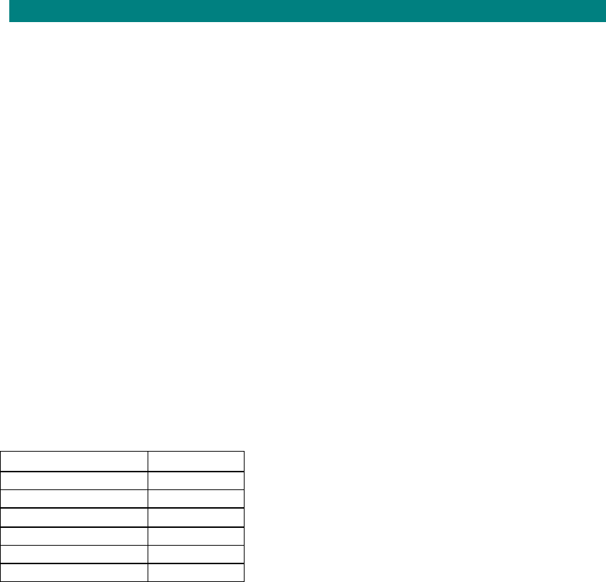
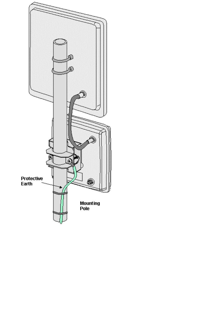
Lightning Protection
1. When the outdoor unit is attached to two / three floor dwellings lightning protection
should not be needed. If the outdoor unit is situated in an exposed position i.e on the
top of a multi-storey building the outdoor unit should be grounded.
2. Run a stranded copper cable from the outdoor unit to a protection earth point i.e
building earth halo or earth provided specifically for lightning protection. The earth
connection from the outdoor unit shall be a minimum of 10 AWG (6 mm2) copper wire
in accordance with UL 96 and 96A. The outdoor unit drop cable shall be run
separately from the earth cable and any cables carrying hazardous voltages.
3. Secure the cable to the pole using straps and cleats as required.
4. Fit a 6mm lug to the cable at the antenna end. Attach to the pole mount bracket using
the lower right M6 set screw as shown below.
5. Connect to the earth point in accordance with local practice.
Lightning Protection for Exposed Pole Mounted Antenna
If the above steps are followed any lightning strike on the outdoor unit mounting bracket
should be discharged safely to earth. Direct strikes on the outdoor unit may cause damage to
the internal components of the outdoor unit and it is also possible that the charge may
damage components in the SIU. The addition of a master socket fitted with discharge tubes
should protect internal wiring and customers premise equipment from damage.
605-0000-595 Subscriber Terminal Installation and Commissioning
60
Installing the IF Unit for External Antenna
Use this procedure to install the IF unit when attaching an external antenna (usually not
supplied by Airspan). These antennas are used when a) additional gain is required to
increase system range. or b) improved isolation to interference is required by narrowing
antenna beamwidths. The mounting pole is not an Airspan supplied item and the pole should
be manufactured to suit local requirements. Before installing the antenna check that the
proposed position meets the site selection guidelines.
Country Specific Requirements
USA: In the USA the antenna shall be installed in accordance with articles 725, 800, 810 and
820 of the National Electrical Code
Canada: In Canada the antenna shall be installed in accordance with section 54 of the
Canadian Electrical Code
External antenna specific requirements
Impedance = 50ohms
Outdoor unit connector type = N-type
VSWR (max) =1.5:1
Signal power (max) = 200mw
The IF unit mounting kit comprises:
IF Unit
Item Quantity
Pole Bracket 1
M6 x 50mm Bolts 4
M6 Coiled Washer 4
M6 Plain Washer 4
Rubber Boot 2
Cable Tie 3
IF Unit Positioning and Securing.
STEP PROCEDURE
1. Confirm the position of the antenna ensuring that there is no obstruction in front and
to either side.
2. When multiple STs are deployed at the same site the recommended minimum
spacing between each antenna is 1 metre.
3. The antenna mounting pole should be fixed so that antenna panning can take place
in the horizontal plane and check that line of sight with CT antenna does not breach
the deployment rules. The antenna mounting pole is locally provided and should be
38mm or 1.5" in diameter. The pole should be fixed according to the pole
manufacturers’ instructions.
4. Note: Leave adequate clearance around the antenna assembly to allow for the full
adjustment range when aligning the antenna.
5. Secure the IF unit to the mounting bracket using the pole bracket secured by four
M6*50mm hex head set screws, 6mm flat, and 6mm coiled washers as shown in the
figure below. Tighten the set screws to a torque of 1.75Nm
Installation
61
6. Secure the IF unit to the pole using the other part of the mounting bracket using M6
Crosshead screws
7. Secure the IF unit to the mounting bracket using the pole bracket using the mounting
brackets and instructions provided with the external antenna.
8. Rotate the antenna to face in the general direction of the CT. At this stage, only
tighten the pivot bolts sufficient to stop the antenna sliding down the pole. After
panning tighten the nuts to the torque specified by the antenna manufacturer
9. Using a connecting cable plug the N-Type connectors into the connector on the rear
plate of the antenna and the IF unit. The length of cable between the IF unit and the
antenna is dependant on the losses allowable in the link budget. Important Notice:
Care should be taken when screwing the N-Type connector into the connector on the
rear plate of the antenna to ensure that the connector is not over-tightened as over-
tightening will strip the thread. .
10. Use the rubber boot to seal the cable connections at the IF unit and wrap self
amalgamating tape over the joint of the mated connectors to the antenna. When
using self amalgamating tape, strip back the interleaving and stretch the tape by
between one third and one half. Keep the tape under tension and wrap, overlapping
successive layers by 50% until the desired build up of insulation is achieved. Finish
the wrapping by holding the tape under the thumb and snap by stretching. The high
degree of stretch as described above prevents the inclusion of voids and ensures
rapid amalgamation
605-0000-595 Subscriber Terminal Installation and Commissioning
62
Typical External Antenna Installation
Lightning Protection
1. When the antenna is attached to two / three floor dwellings lightning protection should
not be needed. If the antenna is situated in an exposed position i.e. on the top of a
multi-storey building the antenna should be grounded.
2. Run a stranded copper cable from the outdoor unit to a protection earth point i.e
building earth halo or earth provided specifically for lightning protection. The earth
connection from the outdoor unit shall be a minimum of 10 AWG (6 mm2) copper wire
in accordance with UL 96 and 96A. The outdoor unit drop cable shall be run
separately from the earth cable and any cables carrying hazardous voltages.
3. Secure the cable to the pole using straps and cleats as required
4. Fit a 6mm lug to the cable at the outdoor unit end. Attach to the pole mount bracket
using the lower right M6 set screw
5. Connect to the earth point in accordance with local practice.

Installation
63
Installing Drop Cable
Drop Cable Installation
Drop cable is provided in two types 6 Series and 11 Series (low loss). Use this procedure to
install the drop cable.
STEP PROCEDURE
1. The drop cable is normally provided with one end already terminated with an weather
proofed F-Type connector for use at the Outdoor Unit. The cable is manufactured in
three lengths (25, 50 and 75metres) and an appropriate length should be selected. In
some circumstances cable is provided on 300metre drums and both ends of the cable
are terminated during installation.
2. If the drop is not pre-terminated and requires an F type terminating at the outdoor unit
end. It is suggested that the F-Type connector is terminated to the free end of the
cable before running the cable. See Drop Cable Termination (6 series) or Drop Cable
Termination (11 series)
3. The cable is installed starting from the antenna end leaving the free end of the cable
to be finally dressed into place and cut to length for neat connection with the power
supply unit.
4. Run the drop cable from the outdoor unit end to the F-Type connector to the SIU.
5. The maximum drop cable distance between the SIU and the outdoor unit must not
exceed the length of the drop cable (50 or 75 metres).
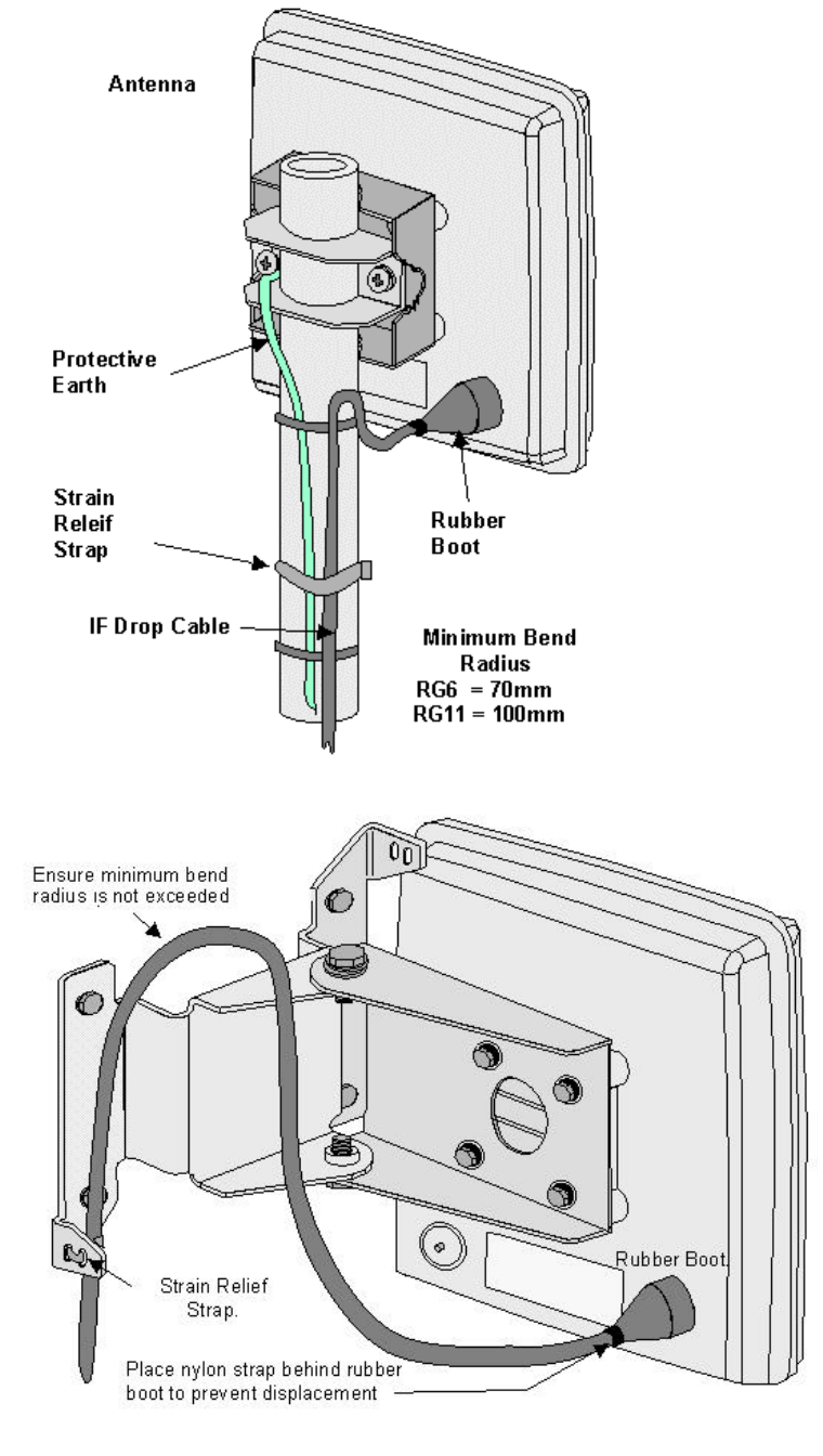
6. The 6 series cable has a minimum bend radius of 70mm. The 11 series cable has a
minimum bend radius of 100 mm
7. Secure the drop cable to the antenna mounting bracket or pole using straps. Leave
sufficient slack to allow for antenna panning at the commissioning stage.
8. Secure along the drop with 7mm cleats as required. Ensure that a drip loop is formed
at the point where the cable enters the building to avoid the ingress of water into the
building.
9. Plug the F-Type connector into the connector on the rear plate of the outdoor unit.
Important Notice: Care should be taken when screwing the F-Type connector into the
connector on the rear plate of the outdoor unit to ensure that the connector is not
over-tightened as over-tightening will strip the thread. Use a torque spanner set to
2.3Nm. See figures below for pole mount and for wall mount installation.
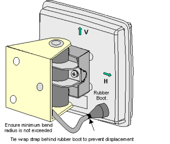
10. a) Use rubber boot to provide environmental seal if provided as part of the
installation kit Push the rubber boot over the connector and ensure that it mates
properly with the raised plastic ring on the outdoor unit housing. Once the boot is in
place a tie wrap should be placed around the cable behind the boot to ensure that the
boot does no become displaced.
or
b) Wrap self amalgamating tape over the joint of the mated connector. When using
self amalgamating tape, strip back the interleaving and stretch the tape by between
one third and one half. Keep the tape under tension and wrap, overlapping successive
layers by 50% until the desired build up of insulation is achieved. Finish the wrapping
by holding the tape under the thumb and snap by stretching. The high degree of
stretch as described above prevents the inclusion of voids and ensures rapid
amalgamation.
11. Run cable end up to the SIU. Estimate the length of end required for termination of
cable (allow 150mm of conductor for a maintenance re-termination of cable) and cut
cable to length.
12. Terminate the drop cable. For termination instructions see Drop Cable Termination (6
Series) or Drop Cable Termination (11 Series)
605-0000-595 Subscriber Terminal Installation and Commissioning
64
Outdoor unit and Drop Cable fixed to a Mounting Pole
Outdoor Unit and Drop Cable fixed to a Wall Mounting Bracket
Installation
65
605-0000-595 Subscriber Terminal Installation and Commissioning
66
Drop Cable Termination Using Crimp Type Connectors
Termination of 6 series drop cable
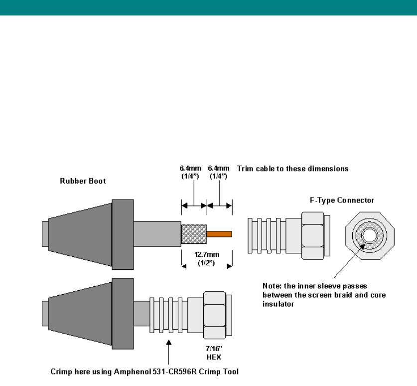
1. If at the antenna end of the drop cable place a rubber boot over the end of the cable.
The boot is not required at the SIU.
2. Strip the drop cable using a knife or cable stripping tool to the dimensions shown
below.
3. Place the connector over the cable end ensuring that the inner sleeve passes
between the inner core and screen braid
4. Crimp the connector using the RG6 round crimp tool contained in the ST installation
tool box or a Amphenol 531-CR596R crimp tool.
Terminating F-Type Connectors to 6 Series cable
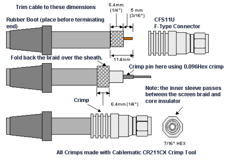
Termination of 11 series drop cable
1. If at the outdoor unit end of the drop cable place a rubber boot over the end of the
cable. The boot is not required at the SIU.
2. Strip the drop cable using a knife or cable stripping tool to the dimensions shown in
figure below
3. Fold back the braid against the cable sheath.
4. Ensure that the centre conductor is clean of dielectric residue. Push the crimp pin
over the end of the centre conductor until the pin bottoms against the dielectric, then
crimp the pin to the centre conductor with the 0.96 Hex crimp on the.RG11 hexagonal
crimp tool contained in the ST installation tool box.
5. Insert the cable into the connector ensuring the pin is through the hole of the insulator
at the bottom of the nut. Continue inserting the cable into the connector until it
bottoms out. Crimp the connector with the 0.475 hex crimp to retain the cable.
Installation
67
Terminating F-Type Connectors to 11 series cable
605-0000-595 Subscriber Terminal Installation and Commissioning
68
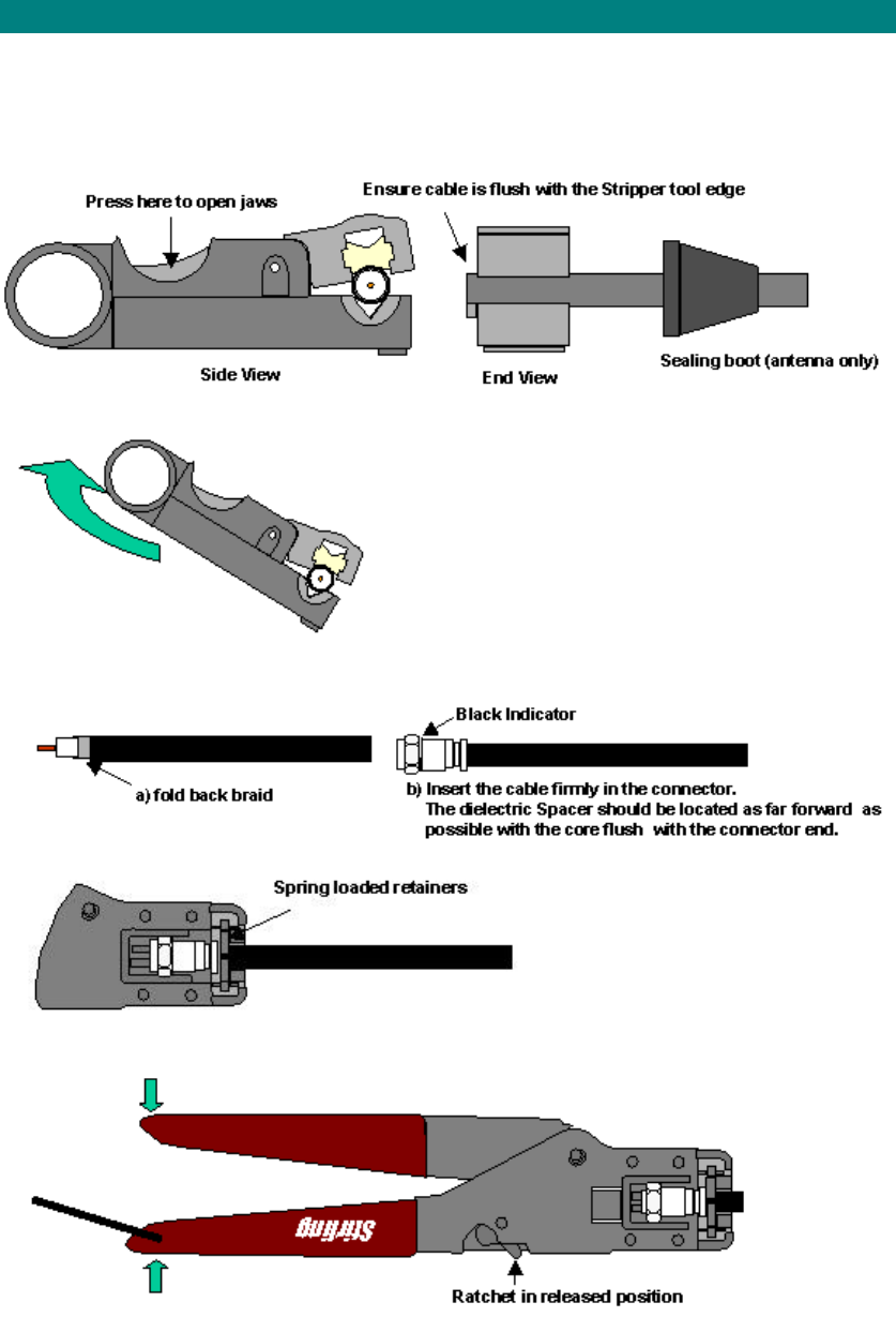
Drop Cable Termination Snap and Seal Connectors
Termination of 6 Series Drop Cable
1. Place cable into jaws of the stripper tool (if at outdoor unit end place sealing boot over the
cable first).
2. Rotate tool 4 turns clockwise then 2 turns anti-clockwise.
3. a) Remove cable from the stripper tool, discard waste and fold back braid.
b) insert cable firmly into the connector as far as possible.
4. Place connector in activator tool by pushing firmly against the spring loaded retainers.
5. Close the handles until the ratchet releases. The black indicator should not be visible if the
connector is correctly crimped.
6. Remove cable from the activator tool.
Installation
69
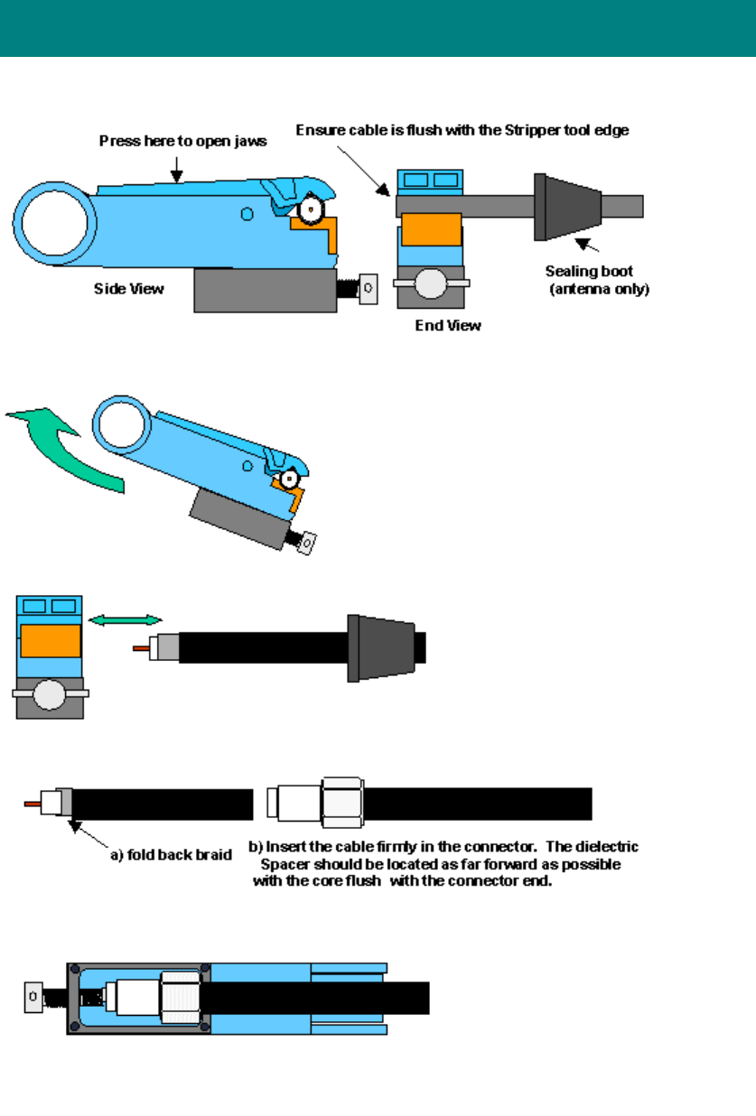
Drop Cable Termination using RG11 Snap and Seal
Connectors
1. Place cable into jaws of the stripper tool (if at outdoor unit end place sealing boot over the
cable first).
2. Rotate tool 4 turns clockwise then 2 turns anti-clockwise
3. Grasp tool firmly and pull cable from the tool to expose braid and centre conductor.
4. A) Fold back braid over the jacket.
B) insert cable firmly into the connector as far as possible.
5. Place connector in activator tool and turn spindle to a positive stop.
6. Remove cable from the activator tool.
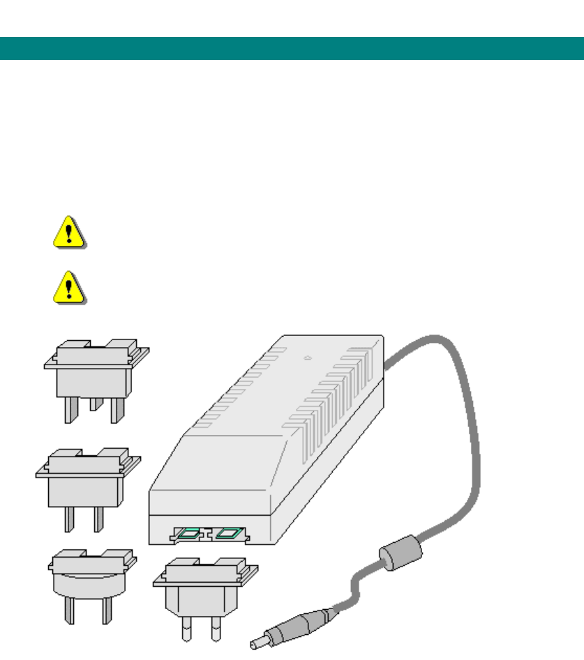
605-0000-595 Subscriber Terminal Installation and Commissioning
70
Installing PSUs
Type 6 PSU
AC Power Supply Unit Type 6
Note: Ensure a good power supply for the ST: PSUs have been connected to intermittent
supplies before, e.g. central heating timers.
1. The Type 6 is a socket PSU that plugs directly into the AC supply socket. It is
supplied with a range of adapters to ensure compatibility with the socket design in the
country of deployment
2. Disconnect Device. The socket outlet shall be installed near the equipment ,
easily accessible and will act as the disconnect for the PSU.
3. The ST-W must use the Type 6C+ PSU part number 261-8000-019
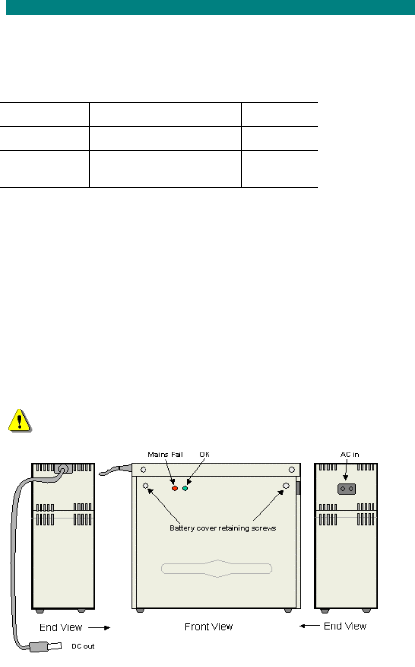
Installation
71
Type 7 PSU
Type 7 PSU s an auto-ranging basic power supply with battery back-up facility
The 7A PSU is an auto-ranging power supply with battery back-up facility. Release 7.15
supports only a 7Ah battery. Connection to the SIU is made using an integral co-axial lead
and D-Type plug connector. LEDs on the PSU indicate the following conditions:
PSU State LED 1
(Green) LED 2
(Amber) Connector
O/P
Normal
operation On Off +V out
Mains fail Off On +V out
Mains &
batteryFail Off Off 0V
The Type-7A can only be used with ST’s that have a 15-way D-type connector.
The 7B PSU is an auto-ranging power supply with battery back-up facility with extended
backup times
Note: Ensure a good power supply for the ST: PSUs have been connected to intermittent
supplies before, e.g. central heating timers. This will shorten the battery life (if fitted)
considerably as it is not designed to be constantly charged and discharged.
PSU (Type 7) Positioning and Securing
STEP PROCEDURE
1. Confirm the position of the Type-7 PSU, allow for adequate ventilation and service access.
Note: The life of the battery within the Type-7 PSU will be increased in a low temperature, but
standby time is improved in a warm environment. Ideally the location should be cool, as the
electronics within the unit will keep it warm enough to ensure a good standby period.
Warning: High voltages exist inside the product do not remove the cover to the main
electronics: No user serviceable parts inside.
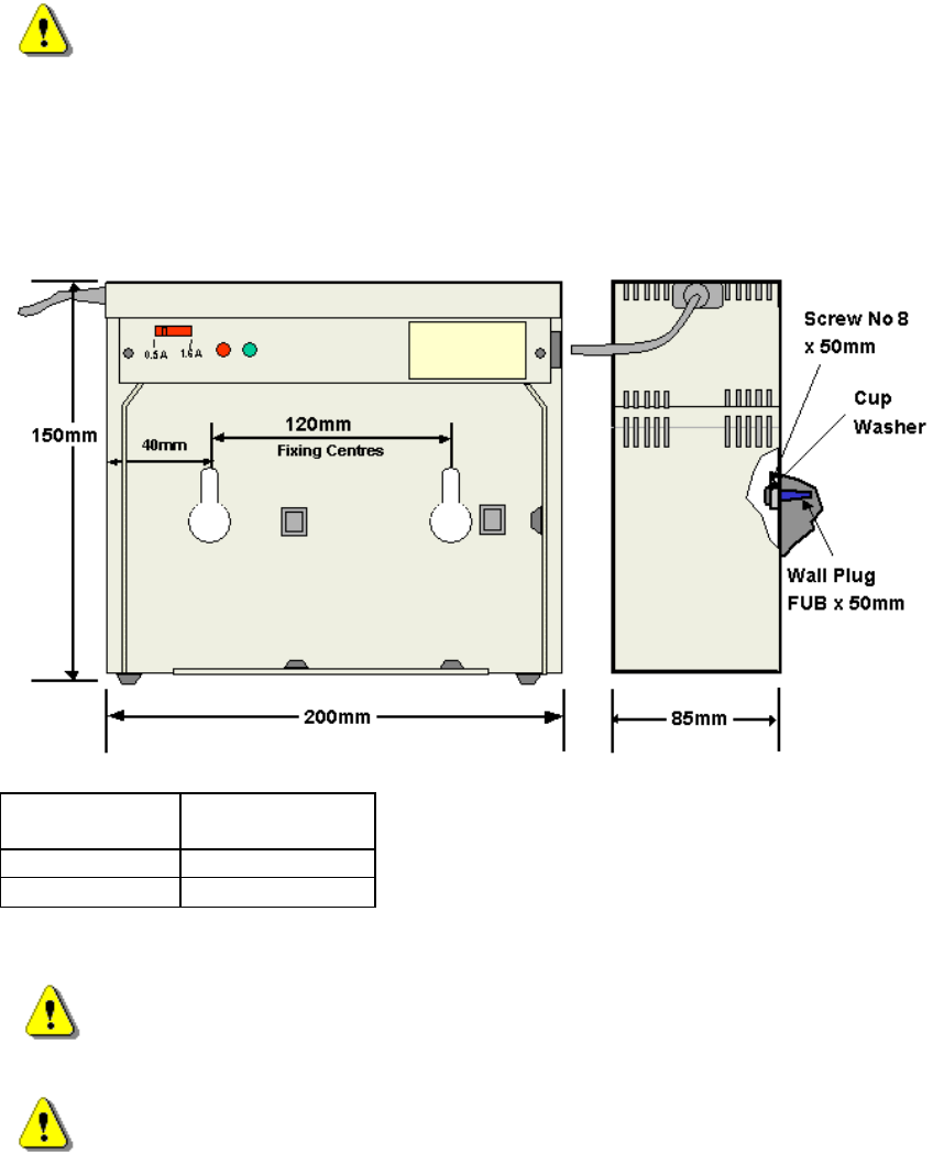
605-0000-595 Subscriber Terminal Installation and Commissioning
72
2. Install the Type 7 PSU within 2 metres of an AC power point and 1 metre of the SIU.
3. The PSU may be freestanding or wall mounted. If wall mounting proceed as follows.
Remove the PSU front cover. Offer the PSU up into position and mark the two fixing positions
onto the wall. The PSU should be fitted with the battery at the bottom and the mains input
connector at the top right hand side.
4. Drill the 2 holes, 8mm. diameter to a depth of 50mm. (use a depth gauge) and then fit the
FUB x 50mm wall plugs (Part No 128-0000-123) provided.
5. Secure the PSU squarely in position using the No 8 x 50mm screws (Part No 174-0815-
002) and cup washers (Part No 192-0080-230) provided.
Installing the Battery
Note:This PSU is suitable for 12 Volt lead acid batteries only.
1. Remove the front cover if not already removed
2. If the SIU is not to be commissioned immediately after installation then do not connect
battery until commissioning is about to take place. If the unit is to be commissioned at this
time. Place the spade connectors onto the battery terminals in the following order:
• Black lead to –ve terminal
• Red lead to +ve Terminal
3. Position the battery in the enclosure and retain using the Velcro straps.
4. Set the battery charging rate
Yuasa Battery Charge rate
select
NP7-12 1.6A
NP12-12 1.6A
5. Fit the cover ensuring that the bottom of the cover locates into the housing and secure with
the two screws at the top of the cover.
CAUTION - Danger of explosion if battery is incorrectly replaced. Replace only with the
same or equivalent type recommended by the manufacturer. Dispose of used batteries
according to the manufacturer's instructions.
Lead acid batteries have a high energy capability and are an energy hazard. The
battery is housed within the protective metal enclosure of the product. This product is not
designed for battery operation outside this enclosure.
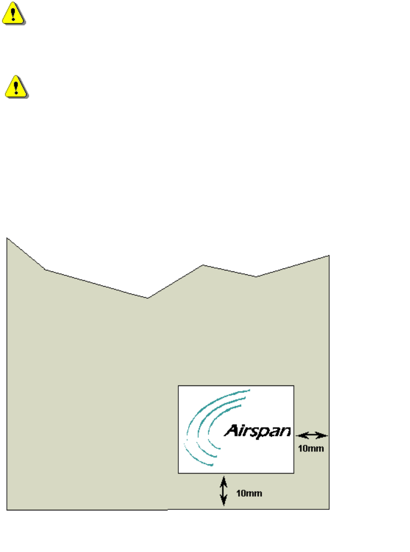
Installation
73
AC Power Cord Installation
STEP PROCEDURE
Safety: Electric Shock: Risk of electric shock disconnect mains before opening the
PSU cover
Use a supply cord fitted with a mains plug in accordance with local requirements. Plug the AC
supply cord into the connector on the Type-7 PSU. Note. Do not connect the plug to the
supply socket until instructed to by the ‘Commissioning Test Procedure’.
Safety: Battery Handling
Care should be taken when handling lead acid batteries to avoid dropping or short circuiting
them. Disposal should be compliant with local codes. Batteries may explode if put into a fire.
Install the batteries in the PSU first, then connect them taking care to observe correct polarity.
Connect red lead to the +ve terminal and the black lead to the - ve terminal.
Disconnect Device. The socket outlet shall be installed near the equipment , easily
accessible and will act as the disconnect for the PSU.
PSU Labelling
If the PSU has been provided with a customer specific logo label, stick the label in the bottom
left hand corner of the front of the case as shown.
Customer Logo Placement
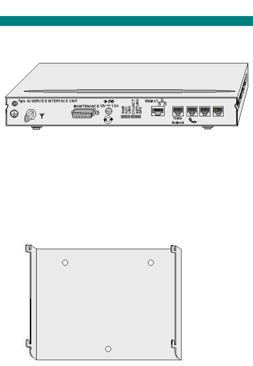
605-0000-595 Subscriber Terminal Installation and Commissioning
126
Installing AS4020 SIUs
Installing P Series SIUs
The P series Service Interface Unit (SIU) is used for packet data and voice can be used as a
free standing desk unit, wall mounted or used in the module enclosure to the customers’
preference. For details on installing the P series into a module enclosure see 'Installing the M
Series.'
The P Series Service Interface Unit (P1V4shown)
Installing the P Series Service Interface Unit
STEP PROCEDURE
1. Confirm the position of the SIU (allow for adequate ventilation, service access and
PSU location).
2. Install the SIU within 1 metre of an AC power point and 50 metres (if using RG6) of
the outdoor unit. (75 metres if using RG11 drop cable).
Wall Mounting the Service Interface Unit
1. The wall mounted unit fits onto the SIU wall mounting bracket.
2. Offer the wall mounting bracket up into position and mark the three fixing positions
onto the wall. The wall mounting bracket should be fitted with the location lugs
pointing upward.
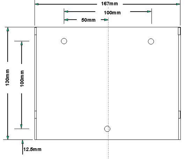
Installation
127
Service Interface Unit Positioning
3. Drill the 3 holes, 8mm. diameter to a depth of 50mm. (use a depth gauge) and then fit
the FUB x 50mm wall plugs (Part No 128-0000-123) provided.
4. Secure the wall mounting bracket squarely in position using the No 8 x 50mm screws
(part no 174-0815-002) and cup washers (part no 192-0080-230) provided.
5. Attach the SIU to the mounting bracket by locating the bracket lugs in the mounting
slots cut into the SIU. The interface connection panel should be at the bottom. Pull
down to lock into position.
Connecting the drop Cable and PSU
1. Plug the F-Type connector on the drop cable into the F-Type Port on the SIU.
2. Important Notice: Care should be taken when screwing the F-Type connector into the
connector on the rear plate of the outdoor unit to ensure that the connector is not
over-tightened as over-tightening will strip the thread. Use a torque spanner set to
2.3Nm (20in lb).
3. Plug the PSU into the wall socket using the appropriate socket adapter and plug the
DC output into the SIU.
Protective Earth
For full compliance with EN 60950 and UL 1950, and for UL certification, this product must be
provided with a protective earth. The protective earth terminal shall be connected to earth
with a conductor no less than 0.75 mm2 and should be either bare or have green/yellow
insulation. Terminate the earth lead with a crimp ring tag at the SIU and with an appropriate
termination at the earth point.
Note: Independent tests carried out by a notified body have demonstrated that the product is
still safe without an earth even though this configuration is not compliant with the standards
stated above.
Connecting the Ethernet to the IDU
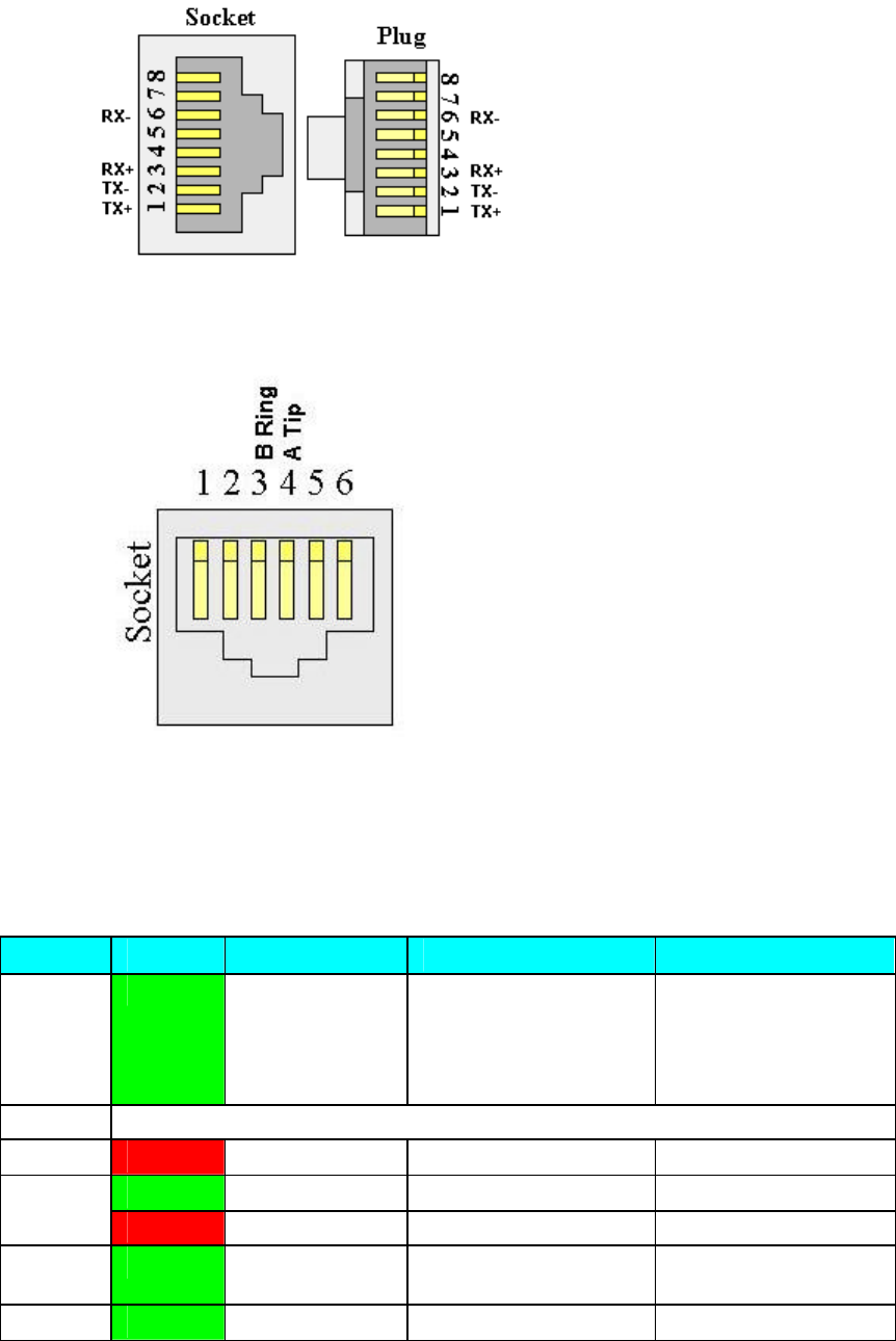
605-0000-595 Subscriber Terminal Installation and Commissioning
128
1. Connect the network card in the PC or the line connection from the hub to the RJ45
port on the SIU
2. Configure the hub or network card to the manufacturers instructions.
3. The RJ45 interface as used for 10baseT connection
Connecting the Telephone (s) to the SIU
1. The RJ11 interface as used for the telephone.
RJ11 Telephone / HomePNA Port
System Management Interface
Front Panel LEDs
Type 41
LED Colour Off On Flashing
Power: Green No input Indicates power OK Switched to Battery
(only for units with
integrated battery or
for power supply with
D-Type connector)
AUX 1 Not defined at present. Illuminates when activity present on the LAT
Link: Red Link is active ST not configured.
Green Data is being sent Col/Act:
Red Collision
Netlink: Green Indicates a valid link is
present
SPD: Green Connected to Connected to Ethernet

Installation
129
low speed
HomePNA. or high speed
HomePNA .
Type 42
LED Colour Off On Flashing
Power: Green No input Indicates power OK Switched to Battery
(only for units with
integrated battery
or for power supply
with D-Type
connector)
AUX 1 Red Awaiting LAC downlink
acquisition Awaiting invite for
NetEntry
Green ST is warm
listening to CCC
CCC management poll in
progress NetEntry in
progress
Orange Voice call on first line in
progress Awaiting TC uplink
Link: Red Link OK (unit
Net Entered) Link is Failed Local (STMON) or
remote
(Sitespan/Netspan)
configuration
missing or
configuration
mismatch detected
Green No activity Indicates activity on the
selected network. May
flash during power up or
when transmit or receive
traffic is detected.
Col/Act:
Red Collision during TX/RX
Netlink: Green Indicates there
is no connection Indicates a valid
connection (Homenet or
Ethernet) has been
established.
SPD: Green Connected to
low speed
HomePNA.
Connected to Ethernet or
high speed HomePNA .
D-type Management Port
The 15 way D-type interface is used for the STMON connection.

605-0000-595 Subscriber Terminal Installation and Commissioning
130
15 way D-type Management Port
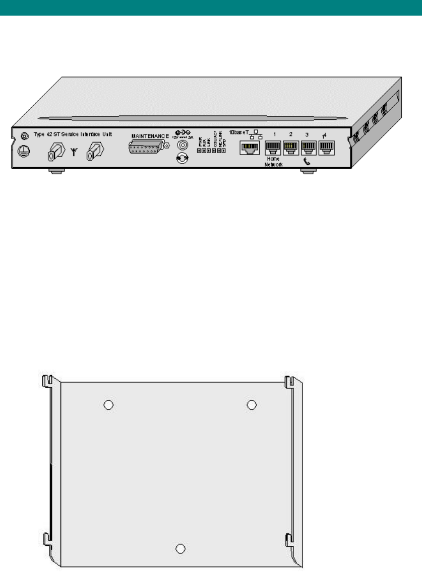
Installation
131
Installing V Series SIUs
The V series Service Interface Unit (SIU) is used for voice can be used as a free standing
desk unit, wall mounted or used in the module enclosure to the customers' preference. For
details on installing the V series into a module enclosure see 'Installing the M Series.'
The V Series Service Interface Unit
Installing the V Series Service Interface Unit
STEP PROCEDURE
1. Confirm the position of the SIU (allow for adequate ventilation, service access and
PSU location).
2. Install the SIU within 1 metre of an AC power point and 50 metres (if using RG6) of
the outdoor unit. (75 metres if using RG11 drop cable).
Wall Mounting the Service Interface Unit
1. The wall mounted unit fits onto the SIU wall mounting bracket.
2. Offer the wall mounting bracket up into position and mark the three fixing positions
onto the wall. The wall mounting bracket should be fitted with the location lugs
pointing upward.

605-0000-595 Subscriber Terminal Installation and Commissioning
132
Service Interface Unit Positioning
3. Drill the 3 holes, 8mm. diameter to a depth of 50mm. (use a depth gauge) and then fit
the FUB x 50mm wall plugs (Part No 128-0000-123) provided.
4. Secure the wall mounting bracket squarely in position using the No 8 x 50mm screws
(part no 174-0815-002) and cup washers (part no 192-0080-230) provided.
5. Attach the SIU to the mounting bracket by locating the bracket lugs in the mounting
slots cut into the SIU. The interface connection panel should be at the bottom. Pull
down to lock into position.
Connecting the drop Cable and PSU
1. Plug the F-Type connector on the drop cable into the F-Type Port on the SIU.
Important Notice: Care should be taken when screwing the F-Type connector into the
connector on the rear plate of the outdoor unit to ensure that the connector is not
over-tightened as over-tightening will strip the thread. Use a torque spanner set to
2.3Nm (20in lb).
2. Plug the PSU into the wall socket using the appropriate socket adapter and plug the
DC output into the SIU.
Protective Earth
For full compliance with EN 60950 and UL 1950, and for UL certification, this product must be
provided with a protective earth. The protective earth terminal shall be connected to earth
with a conductor no less than 0.75 mm2 and should be either bare or have green/yellow
insulation. Terminate the earth lead with a crimp ring tag at the SIU and with an appropriate
termination at the earth point.
Note: Independent tests carried out by a notified body have demonstrated that the product is
still safe without an earth even though this configuration is not compliant with the standards
stated above.
Connecting the Telephone (s) to the SIU
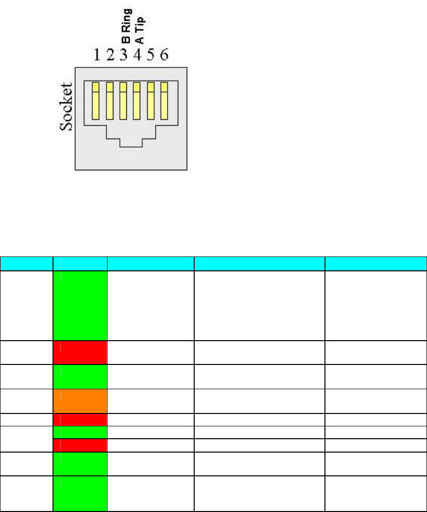
Installation
133
1. The RJ11 interface as used for the telephone connection.
RJ11 Telephone
System Management Interface
Front Panel LED's:
LED Colour Off On Flashing
Power: Green No input Indicates power OK Switched to Battery
(only for units with
integrated battery
or for power supply
with D-Type
connector)
AUX 1 Red Awaiting LAC downlink
acquisition Awaiting invite for
NetEntry
Green ST is warm
listening to CCC
CCC management poll in NetEntry in
progress
Orange Voice call on first line in
progress Awaiting TC uplink
Link: Red Link is active ST not configured.
Green Data is being sent Col/Act:
Red Collision
Netlink: Green Indicates a valid link is
present
SPD: Green Connected to
low speed
HomePNA.
Connected to Ethernet or
high speed HomePNA .
D-type Management Port
The 15 way D-type interface is used for the STMON connection.
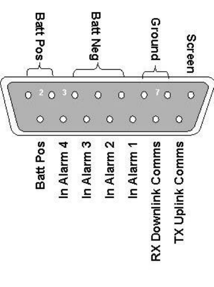
605-0000-595 Subscriber Terminal Installation and Commissioning
134
15 way D-type Management Port
139
Commissioning
Commissioning Steps
Type 41 and Type 42 AS4000
Commissioning Tool Step Activity
STMON ST Meter DVM Telephone
Notes
1 Pre Commissioning
2
Configure Configuring
ST (other than
type 42)
Using
AS7020
STMON
Configuring
ST using a
Test
Telephone
STs may be set
up using
STMON prior to
deployment
3 Panning Panning ODU
using AS7020
STMON
Panning
ODU Using
STMeter
Panning ODU
Using a DVM
5 Fade Margin Checking for Fade Margin using a Fader Cap
6 Functional Tests Functional Tests
Type 42 AS4020
Commissioning Tool Step Activity
STMON ST Meter DVM Telephone
Notes
1 Pre Commissioning
2
Configure Configuring
Type 42 ST
using
STMON
STs may be set up
using STMON
prior to
deployment
3
Panning Panning Type
42 ODU Using
STMON
Panning a
Type 42
ODU using
ST Meter
Panning ODU
Using a DVM
4 Service Tests Service Testing
ST W
Commissioning Tool Step Activity
STMON ST Meter DVM Telephone
Notes
1 Pre Commissioning Pre-installation and Commissioning
2 Setup Type 42 ST
setup using
STMON
3 Panning Panning ODU
using AS7020
STMON
Panning
ODU Using
STMeter
Panning ODU
Using a DVM

605-0000-595 Subscriber Terminal Installation and Commissioning
140
4 Commissioning Commissioning ST W
5 Configuring Configuring the ST W
6 Managing Managing the ST W
7 Reset Reset Options
8 Set Up Access
Parameters Set Up Access Parameters
9 VPNs VPNs
10 Encryption Encryption
11 Advanced Features Advanced Features
12 Service Tests Service Testing

605-0000-595 Subscriber Terminal Installation and Commissioning
166
Type 42
Pre-installation
Before the ST is installed, the installation acceptance criteria should be established. These
are outputs from RF Planning as listed above. They are in summary:
o Corresponding STID
o RF Channel/Pilot Channel
o PN Code
o Expected Downlink Modulation (FEC Mode)
o Expected Uplink Modulation (FEC Mode)
o Required Fade Margin
o Required Downlink SNR
These parameters can be input to STMon during installation. It is expected that the installer
will be informed of these values via a job instruction relating to the particular ST to be
installed.
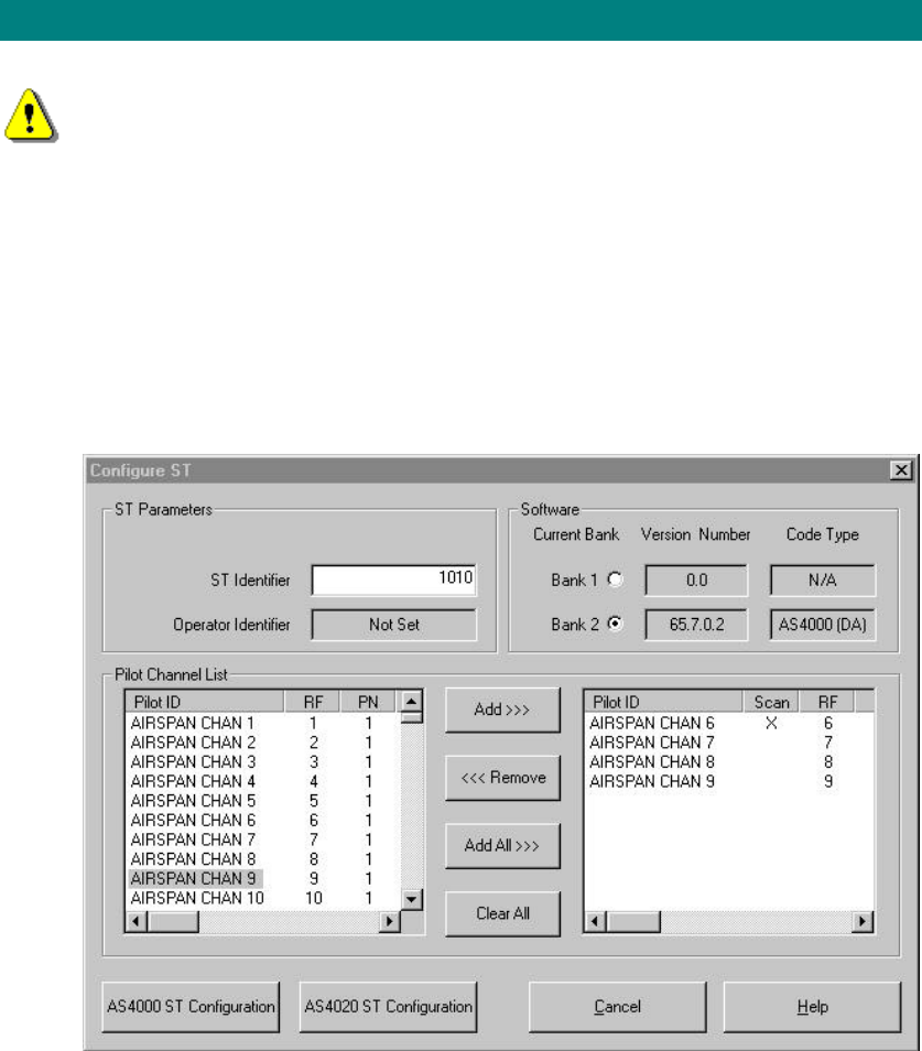
Commissioning
173
Programming Type 42 ST using STMON
Configure a Type 42 Subscriber Terminal
If using STMON software the ST must be powered up and running its application
software before attempting to configure a ST. The boot sequence should be complete
within 1 minute of power on. Failure to do this results in the corruption of the ST
operating software.
Pilot Channels are pre-programmed directly to the ST using STMON as part of the ST
installation process. STMON will allow an ST to have only one Pilot channel pre-programmed
and this channel has to be within the ODUs operating range. The Target channel must also
be within the operating range of the ODU.
1. Select the Setup tab and load the installation file. (For details on editing and creating
installation files see the STMON help file.)
2. Select the Radio Data tab and click left mouse button on the Configure ST button.
3. Enter data into fields on the Configure ST window.
4. Enter the ST ID, this number must be unique for all STs sharing the same CT
5. Select the channels to be made available to the ST in the pilot channel list (left hand
list) using the mouse and click the Add or click the Add All button if all channels are
required. A maximum of ten channels may be selected. If an attempt is made to
select more than ten then a warning message is displayed. The selected channels
appear in the right hand list.
Note: The channels in the pilot channel list (left hand list) are created using the
Installation File Editor (see STMON help file). else the default list of all channels is
loaded.
6. Select the scan channels. Double clicking a channel toggles the scan field. An X
shows that the field is selected. The ST will only scan those channels where the scan
has been enabled. At least one channel needs (exactly one channel for AS4000
configuration) to be enabled or the following message is displayed.
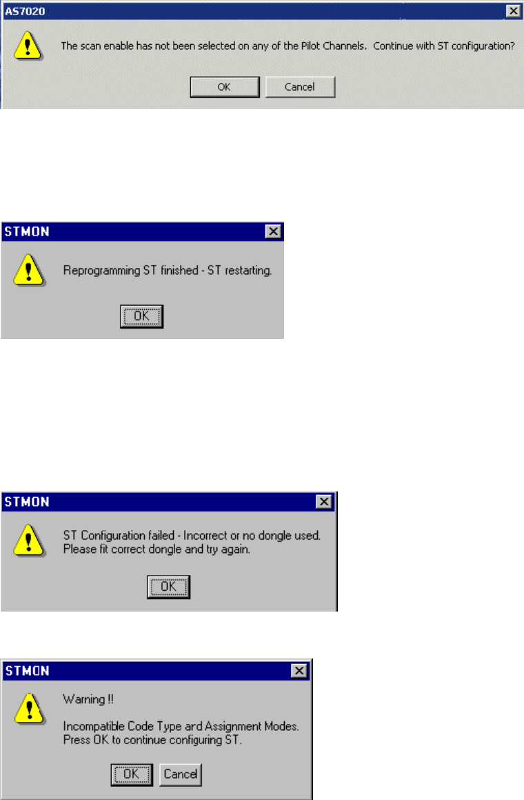
605-0000-595 Subscriber Terminal Installation and Commissioning
174
7. Channels may be removed by selecting the channel and clicking the remove button
for individual channels or using the clear all button to remove all channels.
8. Select the appropriate software bank to run the correct code version.
9. Select either AS4000 ST configure or AS4020 configure Cancel leaves the
configuration unchanged
10. When successfully configured the subscriber Terminal displays a confirmation
message.
Messages displayed if ST fails to configure.
1. The following messages may be displayed should and conflicting data is entered
whilst configuring STMON.
2. Some system administrators use a dongle attached to the serial port of the PC to
prevent the installation of STs by unauthorised persons. If the ST has been previously
programmed with a dongle different from the dongle attached, or if no dongle is
attached to the PC then a warning message is displayed.
3. If the Subscriber Terminal fails to configure because of conflicts between the mode of
working and the software bank then a warning message is displayed. Check that the
Assignment mode and the current bank software are compatible.
4. If the Subscriber Terminal fails to configure for any other reason the following screen
is displayed after 30 seconds.
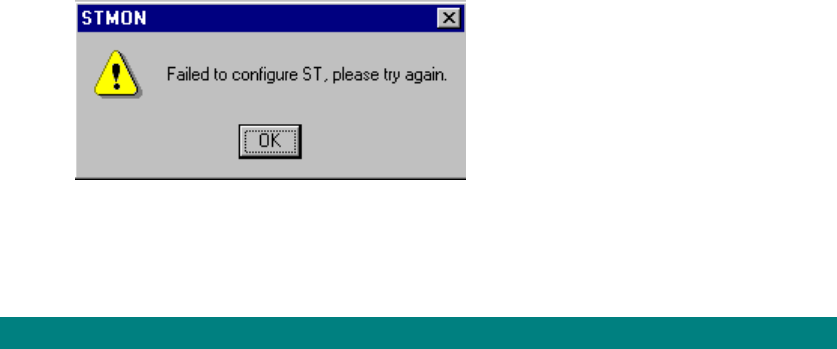
Commissioning
175
Refer to the STMON manual/topics for diagnostics and further information on ST
management
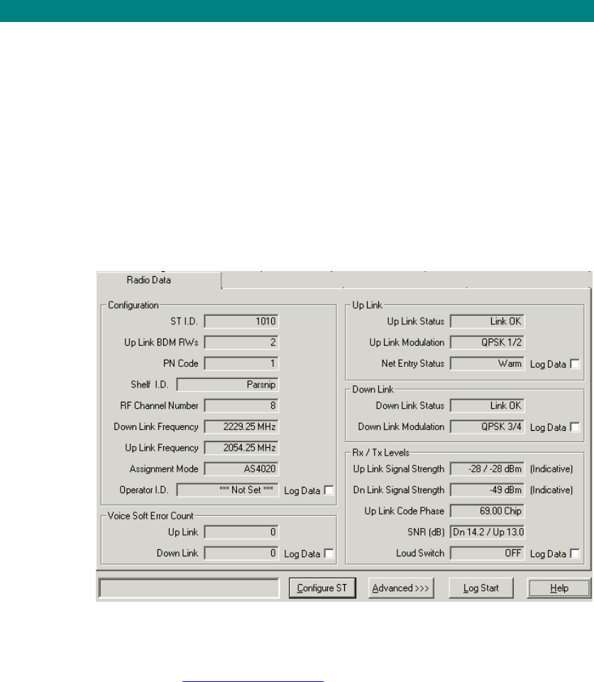
605-0000-595 Subscriber Terminal Installation and Commissioning
176
Panning Type 42 Outdoor Unit Using STMON
Antenna Alignment
Once configured and installed the ST Antenna /ODU will need to be panned to optimise the
RF link quality- SNR, signal strength and fade margin.
STEP PROCEDURE
1. If pole mounted place and tighten a tie wrap immediately underneath the pole bracket
to prevent the assembly sliding down the pole.
2. Loosen the outdoor unit fixing bolts sufficient to allow the antenna to rotate around
the pole.
3. Using compass bearing point the antenna in the direction of the CT (base station)
antenna.
4. Select the Radio Data tab to display ST data. For details of the display see STMON
Display Descriptions
5. Wait for both an uplink and a downlink to be established. If The ST Fails to acquire
check the display to see that the ST has been configured correctly and there is
sufficient signal strength and check compass bearing for CT. Check that the antenna
does not breach the deployment guidelines.
6. If ST supports voice. Connect a telephone to the ST and make a test call
With the call in progress read and record the following from STMON:
a) The receiver power in dBm.
b) The transmitter power in dBm.
c) The downlink SNR
7. Click the Advanced button. Select the Radio Analysis tab. Click the Peak Meter
Button (Alt+p) . The peak meter displays the current downlink signal strength and is
used when panning an antenna to find the strongest signal.The peak downlink signal
strength displays the maximum downlink signal strength measured since the start of
monitoring and can be reset using the Reset Peak Level button (alt s).
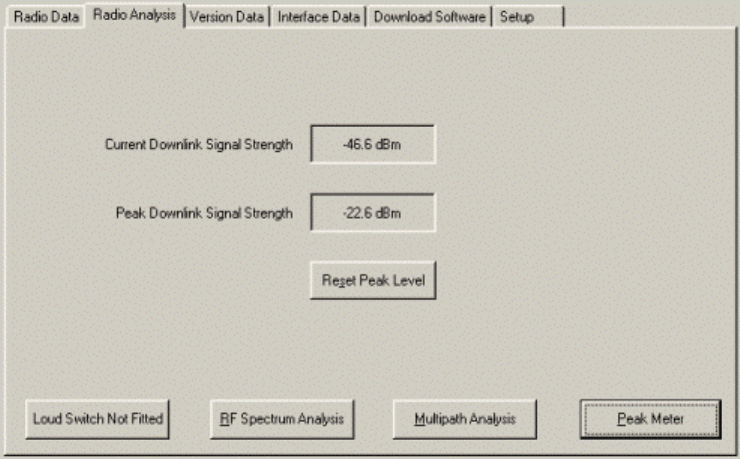
Commissioning
177
8. Pan the antenna unit through a ± 10° azimuth and note down the bearing to which the
Current Downlink Signal Strength is a maximum. This value should be very near to
the peak value shown in the Peak Downlink Signal Strength box.
9. Using a 10mm spanner or socket torque the pivot bolts to 12Nm.
10. If the ST is located close to the CT (likely to be less than 1.5km is used as a
guideline), the receiving signal from the base station is high (likely to be greater than -
50dBm). The loud switch may be used to switch in approximately 30dB of attenuation
to simulate an increase the path loss, which will prevent the RX signal strength from
saturating the ST receiver (saturation of the ST receiver is exhibited as high errors in
the radio link).
Optimise SNR
1. To optimise SNR select the 'Radio Data' tab in STMON make a note of the current
Uplink and Downlink SNR.
2. Select the 'Radio Analysis' tab and click the 'turn loudswitch on' button to turn on the
loudswitch
3. Return to the 'Radio Data' view and observe the change in both the uplink and the
downlink SNR. If the SNR has improved then leave the loud switch turned on. If the
SNR has deteriorated then return to the 'Radio Analysis' view and turn the loudswitch
off.
4. Finally check that the SNR has returned to its previous level.
Link Quality / Modulation rate check
STMON is able to monitor the following link quality parameters:
o Current Downlink Modulation/FEC mode
o Receive SNR Margin
o Receive Fade Margin
o Current Uplink Modulation/FEC mode
o Transmitter Fade Margin
Each of these parameters are compared with the entered installation acceptance criteria and
pass/fail indicators displayed on STMON.
In order to enhance the accuracy of the fade margin measurement, the IF Cable type and
length (to the nearest metre) should be entered into STMON.
In order to further enhance the accuracy of the fade margin measurement, the Tx & Rx gain
offsets for a particular RF channel can be entered into STMON. These are supplied with the
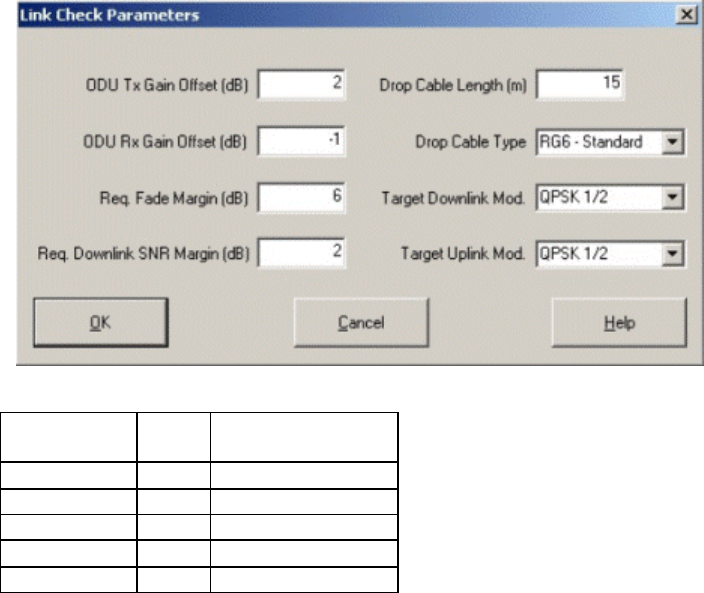
605-0000-595 Subscriber Terminal Installation and Commissioning
178
ST ODU on a printed ticket and will typically enhance the accuracy of fade margin
measurements made at channels other than the mid channel by approx 2dB.
Open STMON and select Link Check tab.
Link Check Parameters
1. Click 'Set Parameters' to display the data entry window.
The table below shows the fade margin required for each modulation rate
Modulation
Code Rate SNR ratio
Minimum
QPSK 1/2 8.3 dB
QPSK 3/4 11.4dB
16QAM 1/2 15.4dB
16QAM 3/4 18.5dB
64QAM 24.8dB
2. Each ST ODU has a TX and RX relative gain recorded on a label placed on the ST.
These values are entered as link check parameters. In order to check that there is
sufficient fade margin for the target modulation select the modulation required for the
uplink and downlink, the values of required fade margin. and the required downlink
SNR. In order to enhance the accuracy of the fade margin measurement, the IF
Cable type and length (to the nearest metre) should be entered into STMON.
3. In order to further enhance the accuracy of the fade margin measurement, the Tx &
Rx gain offsets for a particular RF channel can be entered into STMON. These are
supplied with the ST ODU on a printed ticket and will typically enhance the accuracy
of fade margin measurements made at channels other than the mid channel by
approx 2dB.
4. Click OK.
5. Each of these parameters are compared with the entered installation acceptance
criteria and pass/fail indicators displayed on STMON.
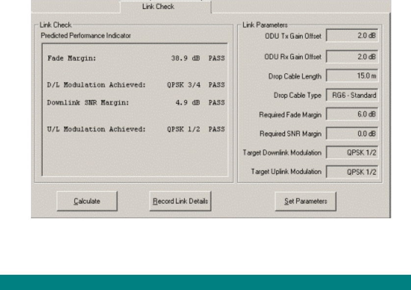
Commissioning
179

Commissioning
183
Service Testing
On completion of the installation / panning of the ST perform an in service test to check that
the ST is capable of making voice and packet calls.
Voice Calls
1. Connect the test telephone to the SIU
2. Dial Tone Present. Lift the telephone handset of Line 1 Off-Hook, and confirm that
dial tone is heard in the handset receiver. If a comfort tone has been set check for
comfort tone prior to dial tone. Record on the 'Test Result' form.
3. Outgoing call. Initiate a call from the subscribers’ telephone to a test number
provided by the CT Office. Ensure that the call can be successfully set up and that
line quality is good.
4. Incoming call. Initiate a return call from the CT Office to the subscribers’ telephone.
Ensure that the call can be successfully set up and that line quality is good.
5. Test Calls. Repeat steps 2 to 4 for all other lines.
IP Check to Internet
1. Connect a Laptop/ PC equipped with a NIC card to the Ethernet Port of the ST
2. Connect using an internet browser.
3. Check that packets can be sent and received over the network
IP Check to Server
1. Connect a Laptop/ PC equipped with a NIC card to the Ethernet Port of the ST
2. Open the Command Prompt (start/programs/accessories/command prompt)
3. From the Command Prompt type ‘ping xxx.xxx.xxx.xxx’ where xxx.xxx.xxx.xxx is the
host server network address and check that a reply is received.
605-0000-595 Subscriber Terminal Installation and Commissioning
184
Test Results Type 42
All results of testing must be entered on this Test Result Form. Please print and photocopy
one for each ST to be commissioned.
Customer ID/Ref: AC Rack ID
CT Rack ID Modem Shelf ID
ST type ST ID:
Outdoor Unit No.: Part No.:
IDU(SIU) Serial No.: Part No.:
Interface (if applicable)
Details and description of RF Path Profile and
local environment
Details and position of Outdoor Unit
Details and Position of SIU/ Module
Enclosure
Test Results
Uplink Signal Strength dBm
Downlink Signal Strength dBm
Downlink SNR dB
Uplink SNR (obtainable via Netspan) dB
Uplink Code Phase Chip
Test Call Voice Lines Tick OK 7.20
Commissioning
185
Internet Access Test OK
FTP Packet Line Data Transfer Rate Kbits/s

605-0000-595 Subscriber Terminal Installation and Commissioning
186
AS4000 Subscriber Terminal Acceptance Form
1. This section includes the Airspan and customer copies of the 'Subscriber Terminal
Acceptance Form'.
2. Photocopy sufficient forms for commissioning, (1 set per ST).
3. After completion give the customer a copy and retain one for ACC.
AS4000 SUBSCRIBER TERMINAL ACCEPTANCE FORM
CONTRACT OR CUSTOMER'S REF. NO:
AIRSPAN COMMUNICATIONS LTD REF .NO:
SITE IDENTITY:
The Customer accepts that the following equipment has been supplied, installed and tested.
ODU Serial No:
Part No:
Outdoor Unit Serial No:
Part No:
PSU Serial No:.
Part No:
Customer Representative
Name: ...................................................................
Position: ...............................................................
Signature: ............................................................. Date: ..............................
Airspan Representative
Name: ...................................................................
Position: ...............................................................
Signature: .............................................................. Date: ..............................
CUSTOMER COPY / AIRSPAN COPY (delete as appropriate)

223
General
Notes for Users
Important Notes
In this leaflet you will find information regarding safety. You should read this carefully and
adhere to the guidelines when using your Subscriber Terminal Unit.
Safety
This device complies with the relevant safety regulations for telecommunications equipment.
If you have any questions regarding the content of this leaflet, contact your sales office or
customer service centre.
• Do not attempt to dismantle the unit or remove access covers (with the exception of
the battery cover).
• Avoid positioning the unit where there is a risk of liquid spillage (eg. near a water
basin). Do not stand beverages on the unit.
• Please ensure that no objects (eg. necklaces, paperclips etc.) or liquids can get into
the interior of the device.
• Lay all cables so that nobody can stand on or trip over them.
• Keep air ventilations clear – leave at least 50mm clearance.
• Stand on a flat surface. Do not stand the unit on a carpet or other soft surface where
air vents on the underneath of the unit may become blocked.
• Do not stand items with a mass of greater than 10kg on the unit.
• Avoid placing the unit exposing the unit to strong magnetic fields (eg. magnetic paper
clip holders and loud speakers).
• Keep this leaflet together with the device. If you pass on the device to third parties,
you should also pass on this leaflet.
Cleaning Notes
• Always remove mains power from the Power Supply Unit (PSU) before you clean any
part of the unit or power supply.
• Do not clean any interior parts yourself. Leave this job to a service technician.
• Do not use any cleaning agents that contain abrasives or may corrode plastic.
• Ensure that no liquid will run into the unit.
• Do not apply cleaning fluid directly to unit – apply the fluid to a soft cloth.
• Do not use any automatic machinery for cleaning the unit (eg. washing machine or
dishwasher)
Wipe the unit housing with a dry cloth. If the unit is particularly dirty, use a cloth which has
been moistened in mild domestic detergent and then carefully wrung out.

225
Glossary
A
A/D: Analogue/Digital
AC: Access Concentrator
ADPCM: Adaptive Differential Pulse Code Modulation
AGC: Automatic Gain Control
AIS: Alarm Indication Signal or All Ones
AMI: Alternate Mark Inversion
AU: Analogue Unit
B
BER: BIT Error Rate
C
CAS: Channel Associated Signalling
CCC: Call Control Channel
CPE: Customer Premises Equipment
CT: Central Terminal
CTU: Concentrated Tributary Unit
CU: Compression Unit
CUG: Closed User Group
D
D/A: Digital/Analogue
DA: Demand Assignment
DACU: Demand Assignment Commissioning Unit
DC: Direct Current
DIP: Diplexer
DMM: Digital Multi Meter
DSP: Digital Signal Processor
DTE: Data Termial Equipment
DTU: Demand Assignment Tributary Unit
F
FA: Fixed Assignment
FRU: Field Replaceable Unit
H
HDLC: High Level Data Link Control
605-0000-595 Subscriber Terminal Installation and Commissioning
226
I
I/0: Input/Output
IP: Internet Protocol
ISDN: Integrated Services Digital Network
ITU-T: International Telecommunications Union -Telecommunications
L
LAT: Local Access Terminal
LED: Light Emitting Diode
LNA: Low Noise Amplifier
M
MF: Multi-Frequency
MODEM: Modulator/Demodulator
MON: Monitor
MSTP: Modem Shelf Termination Panel
MU: Modem Unit
N
NTU: Network Termination Unit
NVRAM: Non Volatile Random Access Memory
O
OOS: Out of Service
P
PA: Power Amplifier
PC: Power Control
PROM: Programmable Read Only Memory
PSTN: Public Switched Telephone Network
PSU: Power Supply Unit
PTU: Packet Tributary Unit
R
RF: Radio Frequency
RTU: Redundant Tributary Unit
RX: Receive
S
SC: Shelf Controller
Glossary
227
SIU: Service Interface Unit
SPU: Signalling Processing Unit
ST: Subscriber Terminal
STP: Shelf Termination Panel
T
TCP: Transmission Control Protocol
TEI: Terminal Equipment Identifier
TU: Tributary Unit
TU8: Tributary Unit Eight E1 ports
TX: Transmit
U
UCP: Uplink Code Phase
V
VDU: Video Display Unit
VF: Voice Frequency
VLan: Virtual Local Area Network
X
XTU: Exchange Tributary Unit

229
Index
1
10BaseT Ethernet..................................1
A
ADPCM.................................................1
Airspan 212-8000-058 Crimp tool .........71
Amphenol 531-CR596R Crimp tool .......71
Analogue Fax/Modem............................1
Antenna Mounting Bracket .....................1
Antenna Mounting Pole..........................1
AS4000 Subscriber Terminals ................1
B
B Series Service Interface Unit ...............1
C
CPE Customer Premises Equipment.......1
D
Downlink
Net Entry ...........................................1
Downlink ...............................................1
Drop Cable Termination.......................71
E
EIA 530.................................................1
Ethernet ................................................1
External Antenna ...................................1
F
FA Fixed Assignment Mode....................1
Fixed Assigned......................................1
Free List................................................1
F-Type .............................................. 113
F-Type Connectors
Terminating......................................71
F-Type Connectors ..............................71
H
HomePNA .............................................1
I
IF 1
IF Drop Cable........................................1
Installing
The R series Service Interface Unit.. 113
Installing ........................................... 113
Interface Units.......................................1
Internal Service Interface Unit.................1
ISDN.....................................................1
L
L Series Service Interface Unit................1
M
M Series Enclosure................................1
MAC.....................................................1
Modular Service Interface Unit................1
Modular Unit..........................................1
Module Enclosure..................................1
Mounting Bracket...................................1
N
N Series Service Interface Unit...............1
Net Entry ..............................................1
NTU Network Termination Unit...............1
P
P Series Service Interface Unit...............1
PacketDrive ..........................................1
PacketDrive ST.....................................1
Panel
SIU Subscriber Interface Unit...........113
Payphones............................................1
Power Supply Units ...............................1
Priority Numbers....................................1
PSU......................................................1
R
R Series Residential Service Interface Unit
.........................................................1
Residential Subscriber Unit ....................1
RS Auto Trim Termination Tool 197-95248
RS Standard Cable Stripper 547-442.... 48
S
S Series Sub Unit Service Interface Unit .1
Service Interface Unit ............................1
ST Subscriber Terminal .........................1
Standby Battery................................... 87
Subscriber Terminal Set-up.................149
Sub-Unit ...............................................1
Sub-Unit Service Interface Unit...............1
System Turn-up..................................149
T
T10 Dropcable..................................... 87
TB1 Connection Block ......................... 87
Terminating
F-Type Connectors........................... 71
Terminating......................................... 71
U
Uplink Code Phase.............................149
Uplink Status......................................149
Using AS7020
Set-up AS4000 STs.........................149
V
V24 ......................................................1
V35 ......................................................1
V90 ......................................................1
Viewing
ST Data..........................................149
Viewing..............................................149
X
X21 ......................................................1
Y
Yuasa Battery Co................................ 87