Airspan Networks AIRSPAN-25G Hybrid System Transceiver User Manual Hardware Installation Guide

Airspan Networks Inc Hybrid System Transceiver Hardware Installation Guide

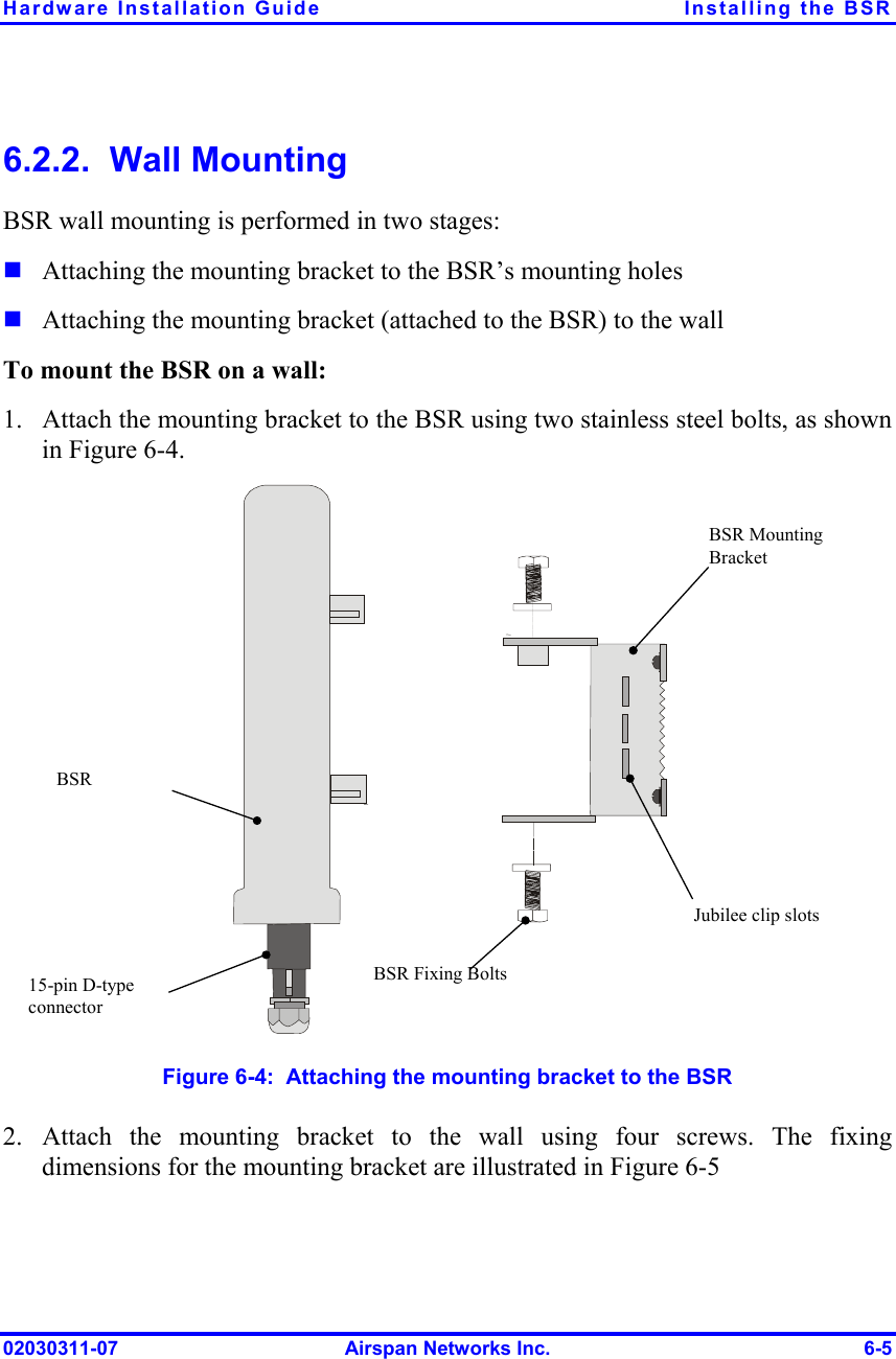
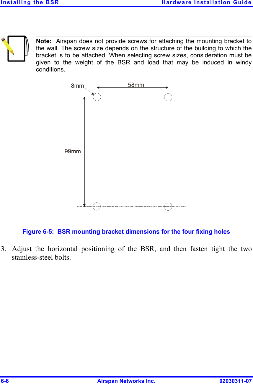
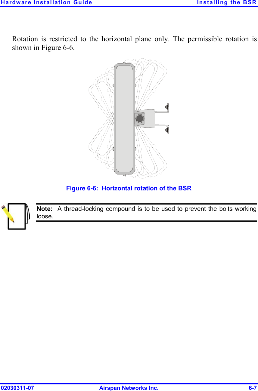
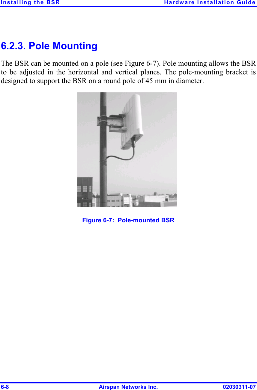
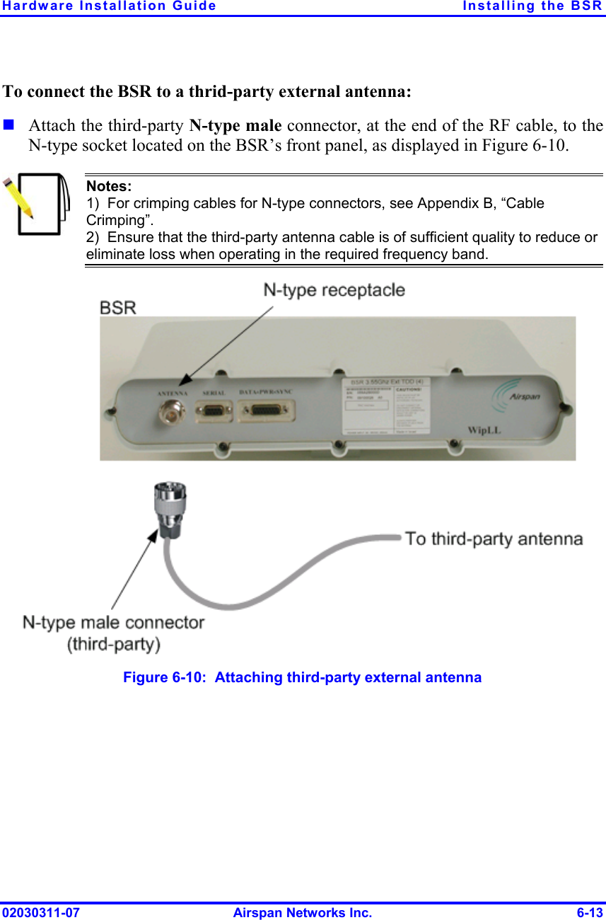
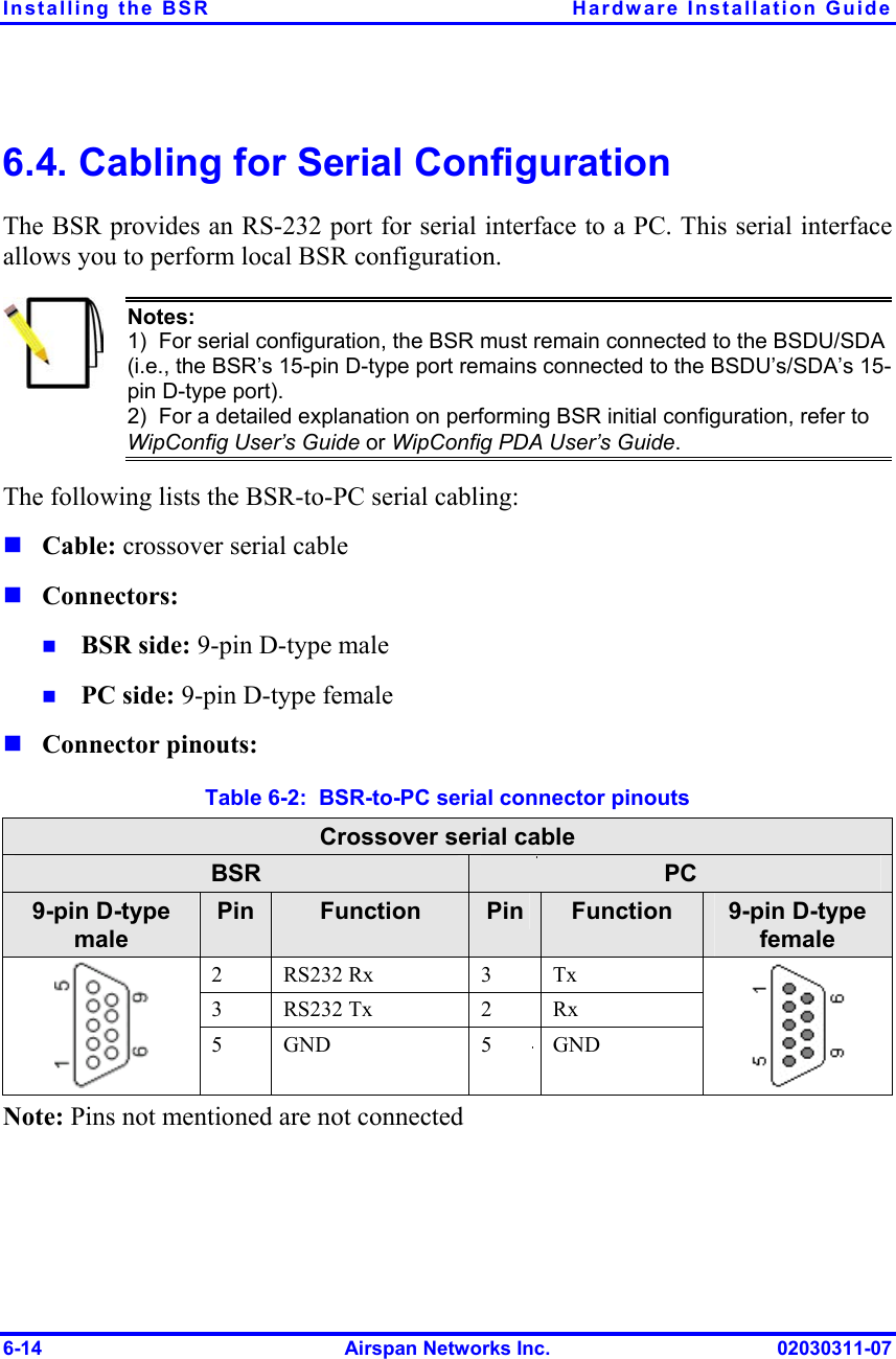
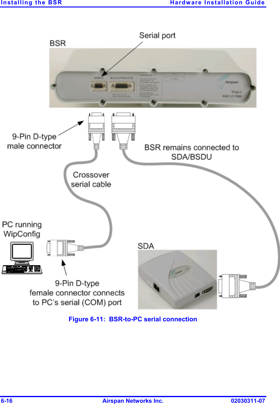
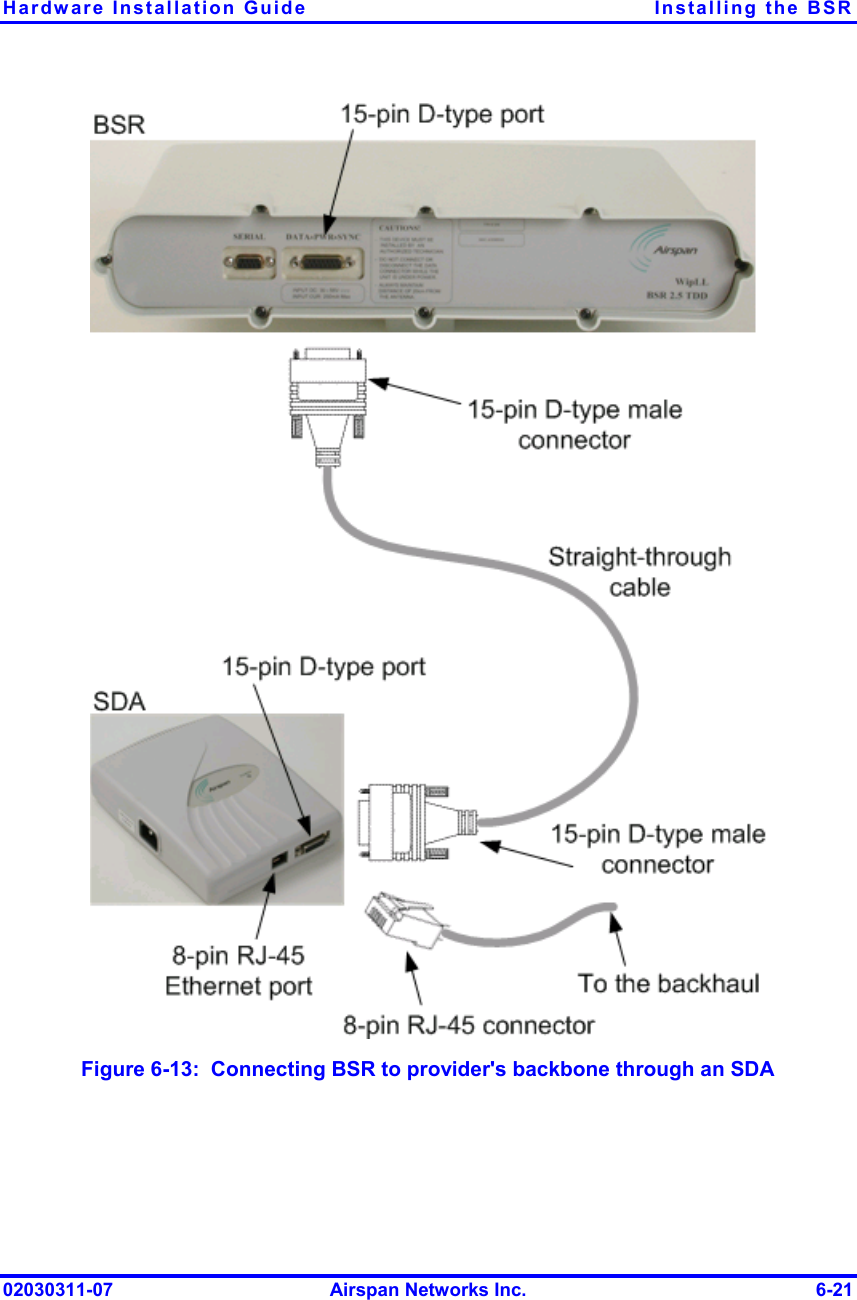
Installation manual bsr

 6   Installing the BSR This chapter describes the installation of the WipLL Base Station Radio (BSR), which is installed at the Base Station.  Warning:  This device must not be co-located or operating in conjunction with any other antenna or transmitter.  Note: The maximum cable length between the BSR and terminating equipment is 100 meters. 6.1. Basic Design and Physical Dimensions The BSR is encased in a chassis providing access to the BSR’s communication ports on the front panel. The BSR’s bottom panel provides holes for mounting the BSR to, for example, a pole or wall. The BSR provides the following ports:   9-pin D-type: RS-232 (serial) interface 15-pin D-type: data, synchronization, and power interface 02030311-07  Airspan Networks Inc.  6-1
Installing the BSR  Hardware Installation Guide    Serial port  Data, synchronization, and power port Figure  6-1:  BSR front panel (built-in antenna model) The BSR’s physical dimensions are described in Table  6-1  Table  6-1:  BSR physical dimensions Parameter  Value  Comment Height  400 mm (15.74 inches) Width  317 mm (12.48 inches) Depth  65.5 mm (2.58 inches) Weight 4.7 kg The BSR’s physical dimensions exclude the mounting kit  6-2  Airspan Networks Inc.  02030311-07
Hardware Installation Guide  Installing the BSR 6.2. Mounting The BSR can be mounted on a wall or pole. The BSR is mounted using the mounting holes located on the BSR’s bottom panel (see Figure  6-2) and the mounting bracket (provided by Airspan).   Mounting holesFigure  6-2:  BSR bottom panel providing holes for mounting  Note:  The BSR must be mounted in a location whereby the antenna used forthe BSR is not co-located or operated in conjunction with any other antenna ortransmitter. 02030311-07  Airspan Networks Inc.  6-3
Installing the BSR  Hardware Installation Guide 6.2.1.  Minimum Distance Between BSRs To prevent radio interference, each BSR requires a minimum of 1-metre separation between adjacent BSRs (see Figure  6-3). 1 Metre min.  Figure  6-3:  Minimum separation between mounted BSRs  Warning: To avoid RF interference between BSRs operating in the 700 MHz, where four BSRs are installed at a Base Station, a 1-meter separation must be provided between the antennas of the BSRs operating in the lower frequencies (i.e., 711.5 and 714.5 for 1 Msps mode; 712 and 714 for 1.33 Msps mode) and the antennas of the BSRs operating in the upper frequencies (i.e., 741.5 and 744.5 for 1 Msps mode; 742 and 744 for 1.33 Msps mode).   Warning: The BSR emits microwave radiation; a minimum distance of200 mm must be maintained from the front of the BSR. However, for the 700 MHz band (i.e. WipLL 700), when external antennas are used, a minimumdistance of 800 mm must be maintained from the front of the device.  6-4  Airspan Networks Inc.  02030311-07
Hardware Installation Guide  Installing the BSR 6.2.2.  Wall Mounting BSR wall mounting is performed in two stages:   1. Attaching the mounting bracket to the BSR’s mounting holes Attaching the mounting bracket (attached to the BSR) to the wall To mount the BSR on a wall: Attach the mounting bracket to the BSR using two stainless steel bolts, as shown in Figure  6-4. Jubilee clip slots BSR BSR Fixing BoltsBSR Mounting Bracket 15-pin D-type connector  Figure  6-4:  Attaching the mounting bracket to the BSR 2. Attach the mounting bracket to the wall using four screws. The fixing dimensions for the mounting bracket are illustrated in Figure  6-5 02030311-07  Airspan Networks Inc.  6-5
Installing the BSR  Hardware Installation Guide  Note:  Airspan does not provide screws for attaching the mounting bracket tothe wall. The screw size depends on the structure of the building to which thebracket is to be attached. When selecting screw sizes, consideration must begiven to the weight of the BSR and load that may be induced in windyconditions.  58mm8mm99mm Figure  6-5:  BSR mounting bracket dimensions for the four fixing holes 3.  Adjust the horizontal positioning of the BSR, and then fasten tight the two stainless-steel bolts. 6-6  Airspan Networks Inc.  02030311-07
Hardware Installation Guide  Installing the BSR Rotation is restricted to the horizontal plane only. The permissible rotation is shown in Figure  6-6.   Figure  6-6:  Horizontal rotation of the BSR  Note:  A thread-locking compound is to be used to prevent the bolts workingloose.  02030311-07  Airspan Networks Inc.  6-7
Installing the BSR  Hardware Installation Guide 6.2.3. Pole Mounting The BSR can be mounted on a pole (see Figure  6-7). Pole mounting allows the BSR to be adjusted in the horizontal and vertical planes. The pole-mounting bracket is designed to support the BSR on a round pole of 45 mm in diameter.  Figure  6-7:  Pole-mounted BSR 6-8  Airspan Networks Inc.  02030311-07
Hardware Installation Guide  Installing the BSR To mount the BSR on a pole: 1.  Attach the mounting bracket to the BSR using two stainless steel bolts. Pivot Hole ‘U’ Bolt  Locking Holes BSR mounting Bracket  Clamping Bracket   Figure  6-8:  BSR mounting bracket assembly 2. 3. Attach the clamping bracket to the mounting bracket using two M8 stainless bolts.  Attach the Clamping bracket to the pole by placing the U-bolt around the pole, and then inserting the U-bolt through the Clamping bracket and securing it by screwing the two bolts on the U-bolt.   02030311-07  Airspan Networks Inc.  6-9
Installing the BSR  Hardware Installation Guide 4. 5. Adjust the vertical position of the BSR. Lock the BSR at the desired position by inserting the locking bolt in the desired position. Once the correct angle has been set both bolts must be tightened to lock the BSR bracket in place. Adjust the horizontal position of the BSR by rotating the BSR about the pole, and then tighten the U-bolt. BSR positioning is obtained in two planes by adjustment of the mounting bracket assembly a shown in Figure  6-9.  Rotation about the mounting poleRotation about the mounting bracket Figure  6-9:  BSR orientation in vertical (top figure) and horizontal plane (lower figure)  Note:  A thread-locking compound is to be used to prevent the bolts workingloose. A loop should be left in the cable for maintenance purposes and to prevent the cable weight being taken directly on the connector. 6-10  Airspan Networks Inc.  02030311-07
Hardware Installation Guide  Installing the BSR 6.3. Connecting Third-Party External Antennas (Optional) A third-party external antenna can be attached to the BSR model providing an N-type port. The addition of an external antenna allows greater RF sector coverage than the standard BSR Internal Antenna model (i.e., 60°). The BSR with an external antenna is especially suited for Base Stations with one BSR, where sector coverage can be increased to 360° by using an omni-directional antenna.  The BSR model for the 900 MHz and 700 MHz bands provide two N-type connectors for attaching two external antennas. This provides dual-antenna diversity.   Warning:  It is the responsibility of the person installing the WipLL system to ensure that when using the outdoor antenna kits in the United States (orwhere FCC rules apply), that only those antennas certified with the product areused. The use of any antenna other than those certified with the product isexpressly forbidden in accordance with FCC rules CFR47 part 15.204. The installer should configure the output power level of antennas according tocountry regulations and per antenna type.  Warning: For WipLL 700 MHz, where four BSRs are installed at a Base Station, a 1-meter separation must be provided between the antennas of the BSRs operating in the lower frequencies (i.e., 711.5 and 714.5 for 1 Msps mode; and 712 and 714 for 1.33 Msps mode) and the antennas of the BSRs operating in the upper frequencies (i.e., 741.5 and 744.5 for 1 Msps mode; and 742 and 744 for 1.33 Msps mode).  Warning:  In accordance with FCC regulations, ensure that when operating in unlicensed bands, the external antennas provide a maximum EIRP of 36 dBm to prevent interference with other radios operating in the unlicensed band. The EIRP is defined as: Max. Power Output + Antenna Gain + Cable Loss ≤ 36 dBm (EIRP)  02030311-07  Airspan Networks Inc.  6-11
Installing the BSR  Hardware Installation Guide The following lists the BSR-to-third party antenna cable setup:   Cable (third party): RF coaxial  Connector  (third party): N-type male (two N-type connectors for BSR model for 900 MHz band. The N-type socket labeled Primary is used only if one antenna is connected. If you are using two antennas for diversity coverage, attach the second antenna to the other N-type socket.)  Warnings:  1)  Before connecting the external antenna, ensure that the BSR is NOT connected to the power source.  2)  Before powering on the BSR, ensure that some type of equipment such as an antenna or an RF attenuator is connected to the N-type socket. This eliminates the risk of damaging the BSR device.  6-12  Airspan Networks Inc.  02030311-07
Hardware Installation Guide  Installing the BSR To connect the BSR to a thrid-party external antenna:  Attach the third-party N-type male connector, at the end of the RF cable, to the N-type socket located on the BSR’s front panel, as displayed in Figure  6-10.  Notes: 1)  For crimping cables for N-type connectors, see Appendix B, “Cable Crimping”. 2)  Ensure that the third-party antenna cable is of sufficient quality to reduce or eliminate loss when operating in the required frequency band.  Figure  6-10:  Attaching third-party external antenna 02030311-07  Airspan Networks Inc.  6-13
Installing the BSR  Hardware Installation Guide 6.4. Cabling for Serial Configuration The BSR provides an RS-232 port for serial interface to a PC. This serial interface allows you to perform local BSR configuration.  Notes: 1)  For serial configuration, the BSR must remain connected to the BSDU/SDA (i.e., the BSR’s 15-pin D-type port remains connected to the BSDU’s/SDA’s 15-pin D-type port).  2)  For a detailed explanation on performing BSR initial configuration, refer to WipConfig User’s Guide or WipConfig PDA User’s Guide. The following lists the BSR-to-PC serial cabling:      Cable: crossover serial cable Connectors: BSR side: 9-pin D-type male PC side: 9-pin D-type female Connector pinouts:  Table  6-2:  BSR-to-PC serial connector pinouts Crossover serial cable BSR  PC 9-pin D-type male Pin  Function  Pin  Function  9-pin D-type female 2 RS232 Rx  3 Tx 3 RS232 Tx  2 Rx  5 GND  5 GND  Note: Pins not mentioned are not connected 6-14  Airspan Networks Inc.  02030311-07
Hardware Installation Guide  Installing the BSR To connect the BSR to a PC for serial configuration (see Figure  6-11): 1. 2. Connect the 9-pin D-type male connector, at one end of the serial cable, to the BSR’s serial port, labeled Serial. Connect the 9-pin D-type female connector, at the other end of the serial cable, to the PC’s serial port.  02030311-07  Airspan Networks Inc.  6-15
Installing the BSR  Hardware Installation Guide  Figure  6-11:  BSR-to-PC serial connection 6-16  Airspan Networks Inc.  02030311-07
Hardware Installation Guide  Installing the BSR 6.5. Connecting to an Ethernet Switch The BSR connects to the provider’s backbone network through either the WipLL BSDU or WiPLL SDA Ethernet switch, depending on the Base Station’s configuration:        Base Station consisting of a single BSR: connection to the backbone may be through an SDA Base Station consisting of multiple BSRs: connection to the backbone is through a BSDU.   6.5.1. Through an SDA For a Base Station consisting of a single BSR, the BSR’s power supply and interface to the backbone network is provided by an SDA, which is typically used at the subscriber’s premises. For a detailed description of the SDA, see Chapter 9, “Installing the SDA”. The following lists the BSR-to-SDA cable setup: Cable: straight-through CAT-5 (100 meters) 4 Pair outdoor type – 24 AWG  Connectors:  BSR side: 15-pin D-type male (only 8 pins are used) SDA side: 15-pin D-type male (only 8 pins are used)  Note:  Airspan supplies unterminated CAT 5 cables for 15-pin D-type connectors. For a detailed description on crimping cables, see Appendix B,“Cable Crimping".  02030311-07  Airspan Networks Inc.  6-17
Installing the BSR  Hardware Installation Guide  Connector pinouts:  Table  6-3:  BSR-to-SDA cable connector pinouts Straight-through CAT-5 UTP PVC 4 Pair 24 AWG cables BSR  SDA 15-pin D-type male  Pin  Function Wire color  Wire pair  Pin  Function 15-pin  D-type male 1 +48 VDC Blue / White 1 +48 VDC 2 -48 VDC Blue 1  2 -48 VDC 3  Tx+  Orange / White 3  Rx+ 4 Tx-  Orange 2 4 Rx- 5  Rx+  Green / White 5  Tx+ 6 Rx-  Green 3 6 Tx- 7  Sync.+  Brown / White 7  Sync.+  8 Sync.-  Brown  4 8 Sync.-    Notes:   1)  Pins 9 through 15 of the 15-pin D-type connector are not used. 2)  The wire color-coding is WipLL's standard for wire color-coding. However, if you implement your company's wire color-coding scheme, ensure that the wires are paired and twisted according to the pin functions listed in Table  6-3 (e.g., Rx+ with Rx-).   6-18  Airspan Networks Inc.  02030311-07
Hardware Installation Guide  Installing the BSR WipLL uses the following wire color-coding standard for CAT 5 cables (8 wires used) connecting outdoor radio units to indoor Ethernet hubs or switches:  Figure  6-12:  WipLL wire color-coding for 15-pin D-type connectors  Note:  The wires are twisted together in pairs, for example, blue/white withblue, and orange/white with orange. This prevents electrical interferencebetween the transmitter pins. For example, pin 3 (Tx+; orange / white) is paired and twisted with pin 4 (Tx-; orange). 02030311-07  Airspan Networks Inc.  6-19
Installing the BSR  Hardware Installation Guide To connect the BSR to the provider's backbone through an SDA: 1. 2. 3. Connect the 15-pin D-type male connector, at one end of the CAT 5 cable, to the BSR’s 15-pin D-type port labeled DATA POWER SYNC. Connect the 15-pin D-type male connector, at the other end of the  CAT 5 cable, to the SDA. Connect the SDA to the provider's backbone.  Note:  For a detailed description of the SDA models, see Chapter 9, “Installingthe SDA”. 6-20  Airspan Networks Inc.  02030311-07
Hardware Installation Guide  Installing the BSR  Figure  6-13:  Connecting BSR to provider's backbone through an SDA 02030311-07  Airspan Networks Inc.  6-21
Installing the BSR  Hardware Installation Guide 6.5.2. Through a BSDU For Base Stations consisting of multiple BSRs, the power supply and interface to the backbone network is provided by the BSDU. The BSR’s 15-pin D-type port is connected to one of the six BSDU’s rear panel 15-pin D-type ports (labeled BSR #).  Note:  For a detailed description of the BSDU, see Chapter 5, “Installing theBSDU”. The BSR-to-BSDU cable setup is as follows:     Cable: straight-through 10Base-T Ethernet 4 Pair Cat 5 outdoor type – 24 AWG (100 meters) Connectors:  BSR side: 15-pin D-type male (only 8 pins are used) BSDU side: 15-pin D-type male (only 8 pins are used)  Note:  Airspan supplies unterminated CAT 5 cables for 15-Pin D-type connectors. For a detailed description on crimping cables, see Appendix B,“Cable Crimping".  6-22  Airspan Networks Inc.  02030311-07
Hardware Installation Guide  Installing the BSR  Connector pinouts:  Table  6-4:  BSR-to-BSDU cable connector pinouts Straight-through CAT-5 UTP PVC 4 Pair 24 AWG cables BSR  BSDU 15-pin D-type male  Pin  Function Wire color  Wire pair  Pin  Function 15-pin  D-type male 1 +48 VDC Blue / White 1 +48 VDC 2 -48 VDC Blue 1  2 -48 VDC 3  Tx+  Orange / White 3  Rx+ 4 Tx-  Orange 2 4 Rx- 5  Rx+  Green / White 5  Tx+ 6 Rx-  Green 3 6 Tx- 7  Sync.+  Brown / White 7  Sync.+  8 Sync.-  Brown  4 8 Sync.-    Notes:   1)  Pins 9 through 15 of the 15-pin D-type connector are not used. 2) The wire color-coding described in the table is WipLL's standard for wire color-coding. However, if you implement your company's wire color-coding scheme, ensure that the wires are paired and twisted according to the pin functions listed in the table above to prevent electrical interference between thetransmitter pins (e.g., Rx+ with Rx-).   02030311-07  Airspan Networks Inc.  6-23
Installing the BSR  Hardware Installation Guide To connect the BSR to the backbone through a BSDU (Figure  6-14): 1. 2. 3. Connect the 15-pin D-type male connector, at one end of the CAT 5 cable, to the BSR’s 15-pin D-type port labeled DATA POWER SYNC. Connect the 15-pin D-type male connector, at the other end of the CAT-5 cable, to one of the six BSDU’s 15-pin D-type ports labeled BSR, located at the rear of the BSDU. Connect one of the BSDU’s 100Base-T ports, located at the front panel, to the backbone (for a detailed description of connecting the BSDU to the backhaul, see Chapter 5, “Installing the BSDU”).   Note:  For a detailed description of cabling the BSDU to the backbone, seeChapter 5, “Installing the BSDU””. 6-24  Airspan Networks Inc.  02030311-07
Hardware Installation Guide  Installing the BSR  Figure  6-14:  BSR-to-BSDU cable connection  02030311-07  Airspan Networks Inc.  6-25
Installing the BSR  Hardware Installation Guide 6.6. Connecting DC Power The BSR is powered by the SDA or BSDU, depending to which unit the BSR is connected. The power is supplied through the BSR’s 15-pin D-type port, which is connected to the SDA or BSDU.  The BSR’s power requirements are described in Table  6-5. Table  6-5:  BSR Power Requirements Parameter  Value  Comment Voltage: •  Minimum •  Maximum 48 VDC nominal •  30 VDC •  55 VDC Voltage is received from the BSDU or SDA Maximum Amperes:  500 mA  --   Warning:  If you are using an external antenna, ensure that you connect theantenna before connecting the BSR to the power source.     Note:  For details on connecting the SDA or BSDU to the mains power supply, see Chapter 7, “Installing the BSDU” and Chapter 9, “Installing the SDA”.  6-26  Airspan Networks Inc.  02030311-07

Navigation menu