Airspan Networks AIRSPAN-700 Hybrid System Tranceiver User Manual ASWipLL HW Installation Guide v08 480
Airspan Networks Inc Hybrid System Tranceiver ASWipLL HW Installation Guide v08 480
Contents
BSR installation guide showing outdoor installation

Leading the World in Wireless DSL
ASWipLL and
AS3010 Systems
Wireless IP-Based Local Loop System
Release 4.8
Hardware Installation
Guide

The ASWipLL product bears the CE marking. This CE marking demonstrates ASWipLL's full compliance with
applicable European Union (EU) directives:
The ASWipLL product bears the Underwriters Laboratories (UL) marking, demonstrating full compliance with UL's
safety requirements:
ASWipLL products also bear the Federal Communications Commission (FCC) marking, demonstrating compliance
with FCC Part 15 regulations.
Revision Record: ASWipLL Hardware Installation Guide
Pub. Rev. Date Update Description
- Nov-00 First edition and printing. (Marconi)
- Mar-01 ASWipLL Release 1.4 (Marconi)
- Apr-01 ASWipLL Release 2.0 (Marconi)
- Jul-01 ASWipLL Release 2.2 (Marconi)
- Nov-01 ASWipLL Release 2.6 (Marconi)
- Jun-02 ASWipLL Release 3.0A (Marconi)
01 Feb-03 ASWipLL Release 4.0. Author: MD. Updates: Airspan template and content
(connector pinouts; cable crimping, and general)
02 May-03 ASWipLL Release 4.2F. Author: MD. Updates: graphics, deleted BSR with serial
port.
03 Jul-03 ASWipLL Release 4.2A. Author: MD. Updates: Chapter 1 for Transparent
Bridging; 5.8 GHz; 2.8 GHz.
04 Aug-03 ASWipLL Release 4.2A. Author: MD. Updates: formatting; graphics; BSDU
LEDs
05 Oct-03 ASWipLL & AS3010 Rel. 42B. Auth: MD. Updates: RSSI Plug for SPR; IDR
RSSI levels; SDA-4S/Vltag; safety guidelines; Append. D.
06 Feb-04 ASWipLL & AS3010 Rel. 4.4. Auth: MD. Updates: RSS LED plug photo
07 Aug-04 Rel. 4.6. Auth: MD. Updates: SDA-1/48V; SDA-1/DC; Link Quality; additional
FCC safety guidelines; Site Planning; miscellaneous.
08 Aug-04 Rel. 4.8. Auth: MD. Updates: surge protector.; ASWipLL 900 ext. ant
Publication No. 02030311-08
Copyright by Airspan Networks INC., 2003. All rights reserved worldwide.
The information contained in this document is proprietary and is subject to all relevant copyright, patent and other
laws protecting intellectual property, as well as any specific agreement protecting Airspan Networks INC. rights in
the aforesaid information. Neither this document nor the information contained herein may be published,
reproduced or disclosed to third parties, in whole or in part, without the express, prior, written permission of
Airspan Networks INC. In addition, any use of this document or the information contained herein for any purposes
other than those for which it was disclosed is strictly forbidden.
Airspan Networks INC. reserves the right, without prior notice or liability, to make changes in equipment design or
specifications.
Information supplied by Airspan Networks INC. is believed to be accurate and reliable. However, no responsibility
is assumed by Airspan Networks INC. for the use thereof nor for the rights of third parties which may be effected
in any way by the use thereof.
Any representation(s) in this document concerning performance of Airspan Networks INC. product(s) are for
informational purposes only and are not warranties of future performance, either express or implied. Airspan
Networks INC. standard limited warranty, stated in its sales contract or order confirmation form, is the only
warranty offered by Airspan Networks INC. in relation thereto.
This document may contain flaws, omissions or typesetting errors; no warranty is granted nor liability assumed in
relation thereto unless specifically undertaken in Airspan Networks INC. sales contract or order confirmation.
Information contained herein is periodically updated and changes will be incorporated into subsequent editions. If
you have encountered an error, please notify Airspan Networks INC. All specifications are subject to change
without prior notice.
Main Operations:
Airspan Communications Ltd.
Cambridge House
Oxford Road
Uxbridge
Middlesex
UB8 1UN
United Kingdom
Tel: (+44) 1895 467 100
Web site: http//www.Airspan.com
This page is intentionally left blank.

Hardware Installation Guide Contents
02030311-08 Airspan Networks Inc. v
Contents
1. Overview .................................................................................................. 1-1
1.1. Introduction ......................................................................................... 1-1
1.2. System Architecture ............................................................................ 1-2
1.3. Base Station Units............................................................................... 1-4
1.3.1. Base Station Radio (BSR) .................................................... 1-5
1.3.2. Point-to-Point Radio (PPR)................................................... 1-5
1.3.3. Base Station Distribution Unit (BSDU) ................................. 1-6
1.3.4. SDA-1/48V............................................................................ 1-6
1.3.5. Global Positioning System (GPS) - Optional ........................ 1-6
1.3.6. Base Station Power Supply (BSPS) - Optional .................... 1-7
1.4. Subscriber Site Units........................................................................... 1-8
1.4.1. Outdoor Radio (SPR) with Indoor Switch/Hub (SDA)........... 1-8
1.4.1.1. Subscriber Premises Radio (SPR)......................... 1-8
1.4.1.2. Subscriber Data Adapter (SDA)............................. 1-9
1.4.2. Indoor Radio Unit (IDR) Only.............................................. 1-12
2. Safety Guidelines .................................................................................... 2-1
2.1. ASWipLL Radios and Third-Party External Antennas ......................... 2-2
2.2. Electrical Safety Guidelines................................................................. 2-5
2.2.1. Handling Electrostatic Devices ............................................. 2-5
2.2.2. Grounding............................................................................. 2-6
2.2.3. Lightning Protection.............................................................. 2-6
2.3. Cabling ................................................................................................ 2-7
2.3.1. Considerations...................................................................... 2-7
2.3.2. Labeling ................................................................................ 2-9
2.3.2.1. Voltage Warning .................................................... 2-9
2.3.2.2. High Earth Leakage Current ................................ 2-10
2.3.2.3. Signal Cable Designation..................................... 2-10

Contents Hardware Installation Guide
vi Airspan Networks Inc. 02030311-08
3. Package Contents ................................................................................... 3-1
3.1. Base Station Equipment...................................................................... 3-1
3.1.1. BSR ...................................................................................... 3-2
3.1.2. BSDU.................................................................................... 3-3
3.1.3. SDA-1/48V............................................................................ 3-4
3.1.4. BSPS .................................................................................... 3-4
3.1.5. GPS ...................................................................................... 3-5
3.2. Customer Premises Equipment........................................................... 3-5
3.2.1. SPR ...................................................................................... 3-6
3.2.2. RSSI LED Adapter................................................................ 3-6
3.2.3. SDA-1, SDA-4H and SDA-4S Models .................................. 3-7
3.2.4. SDA-1/DC............................................................................. 3-7
3.2.5. IDR ....................................................................................... 3-8
4. Required Tools ........................................................................................ 4-1
5. Radio Site Planning................................................................................. 5-1
5.1. Minimal Radio Path Obstructions........................................................ 5-2
5.2. Fresnel Zone Clearance...................................................................... 5-2
5.3. Multipath Fading.................................................................................. 5-3
5.4. Spectrum Analysis for Locating Clear Frequencies ............................ 5-4
5.5. Adjacent Base Station Radios............................................................. 5-5
5.6. Calculating Link Budget....................................................................... 5-5
5.7. Radio Antenna Alignment.................................................................... 5-6
5.8. Considerations when Using External Antennas .................................. 5-7
5.8.1. Cable Loss............................................................................ 5-7
5.8.2. Omni-Directional Antennas................................................. 5-10
5.8.3. Operating in 900 MHz......................................................... 5-10
5.8.4. Operating in Band-C for FCC Markets ............................... 5-11
5.8.5. Dual Antenna Receive Diversity ......................................... 5-12

Hardware Installation Guide Contents
02030311-08 Airspan Networks Inc. vii
Part I: Base Station Installation
6. Basic Design of Devices......................................................................... 6-1
6.1. BSR..................................................................................................... 6-1
6.1.1. Models .................................................................................. 6-1
6.1.2. Physical Dimensions ............................................................ 6-2
6.1.3. Ports ..................................................................................... 6-3
6.2. BSDU .................................................................................................. 6-5
6.2.1. Physical Dimensions ............................................................ 6-5
6.2.2. Ports ..................................................................................... 6-5
6.2.3. LED Indicators ...................................................................... 6-6
6.2.3.1. BSR's LEDs ........................................................... 6-7
6.2.3.2. 100Base-T LEDs.................................................... 6-7
6.2.3.3. Status LEDs ........................................................... 6-8
6.3. SDA-1/48V .......................................................................................... 6-8
6.3.1. Physical Dimensions ............................................................ 6-8
6.3.2. Ports ..................................................................................... 6-9
6.3.3. LED Indicators .................................................................... 6-10
6.4. GPS................................................................................................... 6-11
6.4.1. Ports ................................................................................... 6-11
6.4.2. Physical Dimensions .......................................................... 6-11
6.5. BSPS................................................................................................. 6-12
7. Mounting the Devices ............................................................................. 7-1
7.1. Pole-Mounting the BSR....................................................................... 7-1
7.2. Rack Mounting the BSDU ................................................................... 7-9
7.3. Mounting the SDA-1/48V................................................................... 7-10
7.4. Mounting the BSPS (Optional) .......................................................... 7-11

Contents Hardware Installation Guide
viii Airspan Networks Inc. 02030311-08
8. Network Cabling ...................................................................................... 8-1
8.1. BSR Connected to an SDA ................................................................. 8-2
8.1.1. Connecting BSR to SDA....................................................... 8-2
8.1.2. Connecting SDA to Provider's Ethernet Network ................. 8-6
8.2. BSR Connected to a BSDU................................................................. 8-6
8.2.1. Connecting BSR to BSDU .................................................... 8-6
8.2.2. Connecting BSDU to 100BaseT Networks ........................... 8-9
8.2.3. Daisy-Chaining BSDUs ...................................................... 8-11
8.2.4. Connecting BSDU Synchronization Ports .......................... 8-13
8.2.5. Connecting BSDU to PC for SNMP Management.............. 8-16
8.3. BSR Connected to SDA-1/48V.......................................................... 8-19
8.3.1. Connecting BSR to SDA-1/48V .......................................... 8-19
8.3.2. Connecting SDA-1/48V to 10BaseT Network..................... 8-23
9. Serial Cabling .......................................................................................... 9-1
9.1. Serial Cabling BSR to a PC................................................................. 9-2
9.2. Serial Cabling BSDU to a PC .............................................................. 9-4
9.3. Serial Cabling BSPS to a BSDU ......................................................... 9-6
10. Connecting Third-Party External Antennas........................................ 10-1
10.1. Connecting Radio Antennas to BSR ............................................... 10-1
10.2. Connecting GPS Antenna to BSDU ................................................ 10-5
10.2.1. Mounting the GPS ............................................................ 10-5
10.2.2. Connecting the GPS......................................................... 10-6
11. Power Cabling ....................................................................................... 11-1
11.1. Connecting Power to BSDU ............................................................ 11-2
11.1.1. Grounding the BSDU........................................................ 11-2
11.1.2. Connecting Power Source (e.g. BSPS) to BSDU............. 11-3
11.2. Connecting Power to SDA-1/48 ...................................................... 11-6
11.3. Connecting Power to SDA............................................................... 11-8

Hardware Installation Guide Contents
02030311-08 Airspan Networks Inc. ix
Part II: CPE Installation - SPR
12. Basic Design of Devices....................................................................... 12-1
12.1. SPR................................................................................................. 12-2
12.1.1. Models .............................................................................. 12-2
12.1.2. Physical Dimensions ........................................................ 12-3
12.1.3. Ports ................................................................................. 12-4
12.2. SDA................................................................................................. 12-5
12.2.1. Physical Dimensions ........................................................ 12-5
12.2.2. Ports ................................................................................. 12-5
12.2.3. LED Indicators .................................................................. 12-9
12.2.3.1. SDA-4S .............................................................. 12-9
12.2.3.2. SDA-4H............................................................ 12-11
12.2.3.3. SDA-1 .............................................................. 12-12
12.3. RSS LED Adapter ......................................................................... 12-13
12.3.1. Physical Dimensions ...................................................... 12-13
12.3.2. Ports ............................................................................... 12-14
12.3.3. LEDs............................................................................... 12-15
13. Mounting the Devices ........................................................................... 13-1
13.1. Wall Mounting the SPR ................................................................... 13-1
13.2. Mounting the SDA ........................................................................... 13-8
13.2.1. Desktop Mounting............................................................. 13-8
13.2.2. Wall Mounting................................................................... 13-9
14. Network Cabling .................................................................................... 14-1
14.1. Connecting SPR to SDA ................................................................. 14-2
14.2. Connecting SDA to Subscriber's Ethernet Network ........................ 14-4
14.2.1. Connecting to a LAN/PC .................................................. 14-5
14.2.2. Connecting to a Hub......................................................... 14-8
14.2.3. Connecting to a VoIP Network (RGW) ........................... 14-11

Contents Hardware Installation Guide
x Airspan Networks Inc. 02030311-08
15. Serial Cabling ........................................................................................ 15-1
16. Connecting Third-Party External Antennas........................................ 16-1
17. Antenna Alignment using RSS LED Plug Adapter............................. 17-1
18. Power Cabling ....................................................................................... 18-1
18.1. SPR Connected to SDA-1/DC......................................................... 18-2
18.1.1. Housing the Power Connectors........................................ 18-3
18.1.2. Connecting Power Connector to SDA-1/DC..................... 18-4
18.2. SPR Connected to SDA-1, SDA-4H, or SDA-4S............................. 18-5
18.3. Connecting an Optional Surge Protector......................................... 18-7
Part III: CPE Installation - IDR
19. Basic Design.......................................................................................... 19-1
19.1. Models............................................................................................. 19-1
19.2. Physical Dimensions ....................................................................... 19-2
19.3. Ports................................................................................................ 19-3
19.4. LED Indicators................................................................................. 19-4
20. Mounting ................................................................................................ 20-1
20.1. Attaching the Front Cover ............................................................... 20-2
20.2. Desktop Mounting ........................................................................... 20-4
20.2.1. Vertical Desktop Mounting................................................ 20-4
20.2.2. Horizontal-Desktop Mounting ........................................... 20-6
20.3. Wall and Pole Mounting .................................................................. 20-7
20.3.1. Wall Mounting................................................................... 20-7
20.3.2. Pole Mounting................................................................. 20-10
21. Network Cabling .................................................................................... 21-1
22. Serial Cabling ......................................................................................... 22-1

Hardware Installation Guide Contents
02030311-08 Airspan Networks Inc. xi
23. Connecting Third-Party External Antenna.......................................... 23-1
24. Antenna Alignment Using RSS LEDs.................................................. 24-1
25. Power Cabling ....................................................................................... 25-1
A. Glossary...................................................................................................A-1
B. Installing the BSPS .................................................................................B-1
C. Cable Crimping........................................................................................C-1
D. RSS Led Plug Cabling for SPR with DB9 Port......................................D-1
E. RJ-45 to DB15 Adapter for IDU/ODU Connectivity...............................E-1
F. Evaluating Link Quality........................................................................... F-1
G. ASWipLL Products' Technical Specifications......................................G-1
H. Antenna Specifications...........................................................................H-1
I. ASWipLL Product List ............................................................................. I-1
J. Declaration of Conformity ...................................................................... J-1

Contents Hardware Installation Guide
xii Airspan Networks Inc. 02030311-08
This page is intentionally left blank.

02030311-08 Airspan Networks Inc. xiii
About this Guide
This section discusses the purpose, targeted audience, references, organization, and
technical support of the ASWipLL Hardware Installation Guide.
Purpose
This guide describes the procedures for installing Airspan's ASWipLL devices.
These devices include the Base Station Radio (BSR), Base Station Distribution Unit
(BSDU), Base Station Power Supply (BSPS), Global Positioning System antenna
(GPS), Subscriber Premises Radio (SPR), Subscriber Data Adapter (SDA), and
Indoor Data Radio (IDR).
Referenced Documentation
Although this guide provides software configuration information for certain
ASWipLL devices, it is not comprehensive. For detailed software configuration, see
the, , and The following documentation is referenced in this guide:
ASWipLL System Description: provides an overview of the entire ASWipLL
system.
WipConfig User's Guide: Airspan recommends that you refer to this manual for
performing serial initial configuration.
WipManage User's Guide: Airspan recommends that you refer to this guide for
descriptions on managing the ASWipLL devices.
ASWipLL Commissioning Manual: Airspan recommends that you refer to this
guide for descriptions on managing the ASWipLL devices.

About This Guide Hardware Installation Guide
xiv Airspan Networks Inc. 02030311-08
Targeted Audience
This guide is intended for the person who is responsible for installing the ASWipLL
system. This person should be familiar with electronic circuitry and wiring.
Organization of this Guide
This guide is organized into the following chapters and parts:
Chapter 1, "Overview": provides a brief overview of the ASWipLL devices.
Chapter 2, "Safety Guidelines": lists the safety guidelines for handling cables
and electricity during the installation.
Chapter 3, "Package Contents": lists items provided in standard ASWipLL kits.
Chapter 4, "Required Tools": lists the tools required for installing the system.
Chapter 5, "Radio Site Planning": describes radio issues for planning the site
before installation.
Part 1, "Base Station Installation": includes the following chapters concerned
with installing ASWipLL equipment at the Base Station:
Chapter 6, "Basic Design of Devices"
Chapter 7, "Mounting the Devices"
Chapter 8, "Network Cabling"
Chapter 9, "Serial Cabling"
Chapter 10, "Connecting Third-Party External Antennas"
Chapter 11, "Power Cabling"
Part 2, "CPE Installation - SPR": includes the following chapters concerned
with installing an SPR (interfacing with subscriber's network through an SDA) at
the subscriber's premises:
Chapter 12, "Basic Design of Devices"

Hardware Installation Guide About This Guide
02030311-08 Airspan Networks Inc. xv
Chapter 13, "Mounting the Devices"
Chapter 14, "Network Cabling"
Chapter 15, "Serial Cabling"
Chapter 16, "Connecting Third-Party External Antennas"
Chapter 17, "Antenna Alignment using RSS LED Adapter"
Chapter 18, "Power Cabling"
Part 3, "CPE Installation - IDR": includes the following chapters concerned
with installing an IDR at the subscriber's premises:
Chapter 19, "Basic Design"
Chapter 20, "Mounting"
Chapter 21, "Network Cabling"
Chapter 22, "Serial Cabling"
Chapter 23, "Connecting Third-Party External Antenna"
Chapter 24, "Antenna Alignment using RSS LEDs"
Chapter 25, "Power Cabling"
Appendix A, "Glossary": glossary of terms used in this guide
Appendix B, "Installing the BSPS": describes the procedures for installing an
optional third-party Base Station Power System.
Appendix C, "Cable Crimping": describes the crimping procedure for 15-Pin
D-type, N-type, and GPS connectors.
Appendix D, "RSS Led Plug Cabling for SPR with DB9 Port": describes
connector pinouts for SPR-to-RSS LED Adapter cabling when the old SPR
model that provides a 9-pin D-type port is used.
Appendix E, "RJ-45 to DB15 Adapter for IDU/ODU Connectivity": describes
the use of an optional RJ-45 to DB15 adapter for connecting the outdoor radio to
the indoor hub/switch.
About This Guide Hardware Installation Guide
xvi Airspan Networks Inc. 02030311-08
Appendix F, "Evaluating Link Quality": describes the procedures for
evaluating quality of the BSR-SPR link.
Appendix G, "ASWipLL Product Technical Specifications": lists the technical
specifications of the ASWipLL devices.
Appendix H, "Antenna Specifications": lists the technical specifications of
built-in and third-party external antennas.
Appendix I, "ASWipLL Product List": provides a list of all the ASWipLL
products.
Appendix J, "FCC Declaration of Conformity ": provides a declaration of FCC
conformity for the ASWipLL radios.
Conventions
This guide uses the following bulletin conventions:
Warning: Provides information that can prevent and avoid bodily o
r
mechanical harm.
Note: Provides useful information.
Customer Service
For service and support for your ASWipLL system, contact your regional Airspan
representative, or Airspan's Technical Assistance Center (TAC) at:
E-mail: WipLL.tech_support@Airspan.com
Boca Raton Call Center: (+1) 561 893 8679
UK Call Center: (+44) 1895 467 467

02030311-08 Airspan Networks Inc. 1-1
Overview
This chapter provides a brief overview of the ASWipLL system.
1.1. Introduction
Airspan's ASWipLL system provides a low-cost, high-performance point-to-
multipoint IP-based Broadband Fixed Wireless (BFW) Access solution. ASWipLL
provides wireless local-loop (last-mile) connectivity designed to deliver high-speed
data, Voice over IP (VoIP), and multimedia services to residential, SOHO (small
office/home office), and SME (small medium enterprise). ASWipLL offers service
providers an integrated access solution, providing quick-to-market deployment and
low-market entry cost for broadband services.
ASWipLL operates in the licensed band (700 MHz, 925 MHz, 1.5 GHz, 2.3 GHz,
2.5 GHz Multichannel Multipoint Distribution Services - MMDS, 2.8 GHz, and 3.x
GHz - ranging from 3.3 to 3.8 GHz), and unlicensed band (900 MHz, 2.4 GHz ISM,
and 5.8 GHz).
Each ASWipLL Base Station, at maximum configuration, supports up to 3,024
subscribers, providing connectivity speeds of up to 4 Mbps.
ASWipLL enables interconnection with the Public Switched Telephone Network
(PSTN) by the use of an IP-to-PSTN gateway. ASWipLL provides VoIP by its
interoperability with a wide range of third-party products such as residential
gateways (RGW), access gateways, gatekeepers, and softswitches.
1

Overview Hardware Installation Guide
1-2 Airspan Networks Inc. 02030311-08
ASWipLL utilizes air protocol technology for wireless packet switching using
Frequency Hopping technology. ASWipLL's in-house Preemptive Polling Multiple
Access (PPMA) Air MAC protocol technology, which recognizes transmission type
and allocates bandwidth, is highly efficient—80% throughput (e.g. 80% of 4 Mbps =
3.2 Mbps net capacity)—allowing multiple concurrent subscribers to utilize
bandwidth.
ASWipLL provides bandwidth management by supporting both asymmetric and
aggregated Committed Information Rate (CIR) and Maximum Information Rate
(MIR), guaranteeing bandwidth levels to subscribers. In asymmetric CIR/MIR,
different values are defined for uplink and downlink traffic: in aggregated CIR/MIR,
values are defined as the sum of the uplink and downlink traffic.
ASWipLL supports VLANs and VPNs based on IEEE 802.1Q/p. ASWipLL
supports IP routing and PPPoE bridging, as well as transparent bridging.
ASWipLL provides embedded security features such as IP (packet) filtering based
on addresses, protocols, and applications.
The ASWipLL system provides SNMP-based management, allowing remote and
local management, configuration, and monitoring of ASWipLL equipment.
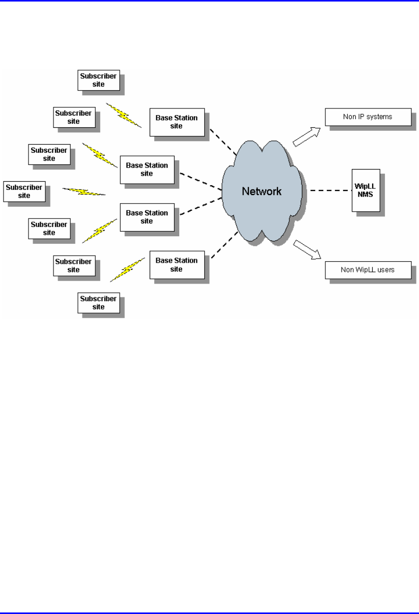
1.2. System Architecture
The ASWipLL system architecture is composed of the following three basic areas:
Base Station site: consists of ASWipLL access units that interface between the
provider's backbone and the ASWipLL subscriber sites.
Subscriber site: consists of ASWipLL customer premises equipment (CPE) that
interfaces between the Base Station and the subscriber's network.
Network management tools: consists mainly of Windows- and SNMP-based
programs, providing fault, configuration, performance, and security management
for the ASWipLL system.
Hardware Installation Guide Overview
02030311-08 Airspan Networks Inc. 1-3
Figure 1-1 displays a block diagram of the ASWipLL system architecture.
Figure 1-1: ASWipLL system architecture
Overview Hardware Installation Guide
1-4 Airspan Networks Inc. 02030311-08
1.3. Base Station Units
The ASWipLL Base Station interfaces between the subscriber sites and the service
provider's backbone, providing subscribers with high-speed data, Internet, and VoIP
services.
The ASWipLL system provides various devices (some optional) for the Base Station
site. The implementation of these devices depends on the desired network (e.g.
point-to-point radio link), number of outdoor radios and power source at the Base
Station, and required synchronization type (i.e. by GPS).
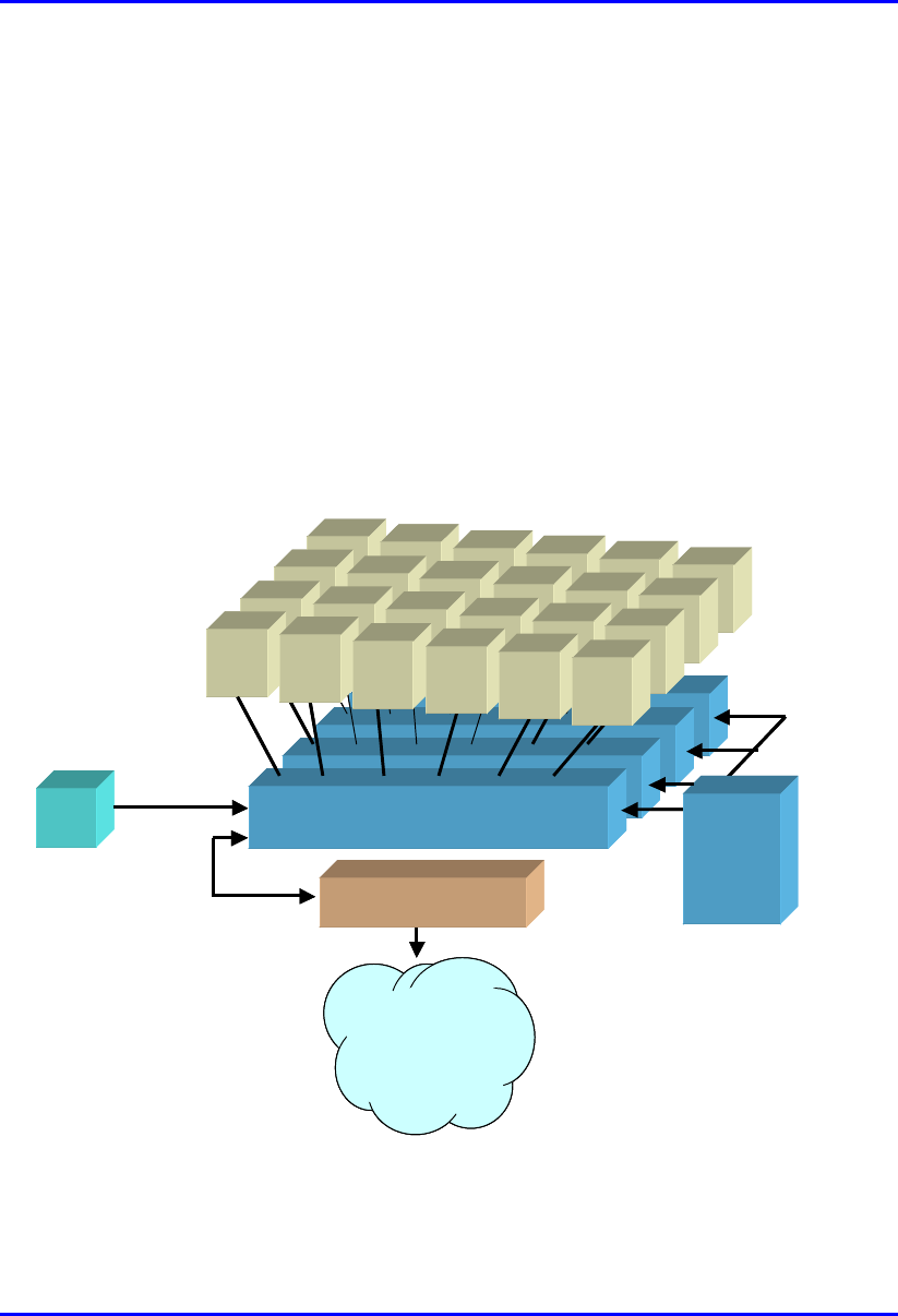
Figure 1-2 shows a fully populated ASWipLL Base Station at maximum
configuration (24 BSRs, 4 BSDUs, 1 BSPS, and a GPS).
BSR
BSDU
BSR BSR BSR BSR BSR
BSR
BSDU
BSR BSR BSR BSR BSR
BSR
BSDU
BSR BSR BSR BSR BSR
BSR
BSDU
-48 VDC
100BaseT
BSPS
BSR BSR BSR BSRBSR
GPS
Backbone
(IP, ATM,FR, MPLS)
Interface unit
(e.g. router, switch)
BSR
BSDU
BSR BSR BSR BSR BSR
BSR
BSDU
BSR BSR BSR BSR BSR
BSR
BSDU
BSR BSR BSR BSR BSR
BSR
BSDU
-48 VDC
100BaseT
BSPS
BSR BSR BSR BSRBSR
GPS
Backbone
(IP, ATM,FR, MPLS)
Interface unit
(e.g. router, switch)
Figure 1-2: ASWipLL Base Station units (maximum configuration)

Hardware Installation Guide Overview
02030311-08 Airspan Networks Inc. 1-5
1.3.1. Base Station Radio (BSR)
The BSR is an outdoor radio unit, typically mounted on a pole or wall, involved in
providing a wireless link between the Base Station and subscribers. The standard
BSR provides 60-degree radio coverage, serving up to 126 subscribers in a sector.
For Base Stations consisting of multiple BSRs, the BSRs are powered, and interface
with the provider's backbone by the ASWipLL Base Station Distribution Unit
(BSDU). For a Base Station consisting of a single BSR, the BSR is typically
powered and connected to the provider's backbone by the ASWipLL Subscriber
Data Adapter (SDA).
1.3.2. Point-to-Point Radio (PPR)
The PPR device is similar to the BSR, but implemented in a point-to-point radio
configuration, providing wireless communication with a single remote subscriber
ASWipLL radio unit (i.e. SPR or IDR).

Overview Hardware Installation Guide
1-6 Airspan Networks Inc. 02030311-08
1.3.3. Base Station Distribution Unit (BSDU)
The BSDU is an Ethernet switch implemented at Base Stations consisting of
multiple BSRs. The BSDU provides 100Base-T interface between the BSRs and the
provider's backbone. The BSDU is also responsible for providing BSRs with –48
VDC power supply and frequency hop synchronization between BSDUs, BSRs, and
Base Stations (when a GPS is implemented).
The BSDU is installed indoors in a standard 19-inch cabinet, and connects to the
BSRs by standard CAT-5 cables. Each BSDU can connect to a maximum of six
BSRs. In addition, up to four BSDUs can be daisy-chained to support a maximum of
24 BSRs. Therefore, a Base Station at maximum configuration can serve up to 3,024
subscribers.
Note: At a Base Station consisting of a single BSR, the BSR typically
interfaces with the provider's backhaul through the SDA instead of the BSDU.
(See Section 1.4.1, "Outdoor Radio (SPR) with Indoor Switch/Hub").
1.3.4. SDA-1/48V
The SDA-1/48V is a compact indoor adapter, especially designed for use when
available power source is 48VDC (i.e. no AC power supply), and when no
synchronization is required (i.e. in licensed bands). The SDA-1/48V provides the
BSR with Ethernet connectivity to the backhaul.
1.3.5. Global Positioning System (GPS) - Optional
The GPS antenna is a rugged, self-contained GPS receiver and antenna that receives
a universal GPS satellite clock signal. The GPS is an optional unit that connects to
the BSDU. The GPS synchronizes frequency hopping of multiple Base Stations,
ensuring that the entire ASWipLL network operates with the same clock based on a
universal satellite clock signal, and, thereby, eliminating radio frequency ghosting
effects.

Hardware Installation Guide Overview
02030311-08 Airspan Networks Inc. 1-7
1.3.6. Base Station Power Supply (BSPS) - Optional
The BSPS is an optional third-party unit that is implemented at Base Stations to
provide –48 VDC power supply and power redundancy. The BSPS is installed in a
standard 19-inch cabinet and connected to the BSDU.
The BSPS provides the BSDUs and BSRs with the following:
Power supply of –48 VDC.
Power redundancy in case of power failure. The BSPS charges a battery bank
that provides this power redundancy during mains failure. Thus, the BSPS acts
as a DC-uninterruptible power supply (UPS) with a battery connected to it. The
size of the battery determines the backup and charging time. Since the system is
current limited, the maximum battery size is based on that limit.
Remote power management and monitoring (by ASWipLL's WipManage
program).
The BSPS consists of the following basic components:
Main unit:
DC Rectifier modules: converts AC current to DC. The BSPS can house up
to four rectifiers. The rectifiers are "hot plugged" and operate in parallel.
This enables the user to define an N+1or N+2 redundant system. Each
rectifier has its own current sharing system, satisfying a complete sharing
among rectifiers.
System controller: provides BSPS management control and BSPS operating
information.
Electronic Low Voltage Detector (ELVD): disconnects the battery from
the load, avoiding damage to the battery when over-discharged.
Load and battery circuit breakers: provide DC protection and distribution.
DC Distribution unit: provides circuit breakers for distributing the output
current to multiple BSDUs. It also contains a bypass switch to bypass the LVD.
Battery: provides the BSPS system with back-up power.

Overview Hardware Installation Guide
1-8 Airspan Networks Inc. 02030311-08
1.4. Subscriber Site Units
The ASWipLL subscriber units are located at the subscriber's premises. The
ASWipLL subscriber site consists of a radio transceiver that receives and transmits
signals from and to the Base Station. The radio transceiver provides the subscriber
with high-speed data access, Internet access, and VoIP at up to 4 Mbps. The
ASWipLL radios interface with the subscriber's Ethernet network either through a
hub or switch, or directly, depending on ASWipLL radio model.
Note: For VoIP support, Airspan can provide a third-party residential gateway
(RGW). The RGW typically provides two POTS ports for telephony, a 10BaseT
LAN port for subscriber PC/network, and a 10BaseT port for connecting to the
SDA or IDR (depending on subscriber site configuration).
The ASWipLL system provides two different subscriber site configurations:
Outdoor radio (i.e. SPR) with indoor Ethernet switch/hub (i.e. SDA)
Indoor radio only (i.e. IDR device)
1.4.1. Outdoor Radio (SPR) with Indoor Switch/Hub
(SDA)
The outdoor radio with indoor Ethernet switch/hub configuration consists of the
ASWipLL Subscriber Premises Radio (SPR) and the ASWipLL Subscriber Data
Adapter (SDA), respectively.
1.4.1.1. Subscriber Premises Radio (SPR)
The SPR is an outdoor radio transceiver that provides a wireless link between the
subscriber's network and the Base Station.
The SPR connects to the subscriber's network through the SDA Ethernet hub/
switch. The SDA provides the SPR with DC power, lightening protection, and
Ethernet (10Base-T and/or 100Base-T) interface with the subscriber's PCs/network
(up to four PCs depending on SDA model).

Hardware Installation Guide Overview
02030311-08 Airspan Networks Inc. 1-9
The SPR is mounted outside on an external wall or on a pole. The SPR connects to
the SDA by a standard CAT-5 cable.
1.4.1.2. Subscriber Data Adapter (SDA)
The SDA is a switch or hub (depending on model), providing the SPR with -48
VDC power supply, lightening protection, and 10/100BaseT interface to the
subscriber's PCs/network.
The SDA is installed indoors and can be mounted on a wall or simply placed on a
desktop. The SDA connects to the SPR by a standard CAT-5 cable.
The SDA is available in the following models:
SDA-1: hub providing one 10BaseT interface with the subscriber's computer (or
LAN network if connected to another hub or a switch).
SDA-1/DC: adapter that provides Ethernet (one 10BaseT) and regulated
–48 VDC power to the SPR. This model can be powered from a voltage of 10 –
52 VDC (e.g. from a solar panel that typically provides 12 VDC). This model is
typically implemented in mobile wireless applications, e.g. in a car or truck.
(This model can also be implemented at a Base Station with a BSR.)
SDA-4H: hub providing four 10BaseT interfaces with the subscriber's
computers and/or networks. One of the 10BaseT ports provides crossover
cabling for interfacing with another hub or LAN switch. Alternatively, it may be
connected to another PC via a crossed Ethernet cable.

Overview Hardware Installation Guide
1-10 Airspan Networks Inc. 02030311-08
SDA-4S: integrated LAN switch, providing four 10/100BaseT interfaces with
the subscriber's PCs/network. The ports of the SDA-4S models support Auto
Negotiation, allowing automatic configuration for the highest possible speed
link: 10BaseT or 100BaseT, and Full Duplex or Half Duplex mode. In other
words, the speed of the connected device (e.g. a PC) determines the speed at
which packets are transmitted through the SDA-4S port. For example, if the
device to which the port is connected is running at 100 Mbps, the port
connection will transmit packets at 100 Mbps. If the device to which the port is
connected is running at 10 Mbps, the port connection will transmit packets at 10
Mbps.
The SDA-4S ports also support automatic MDI/MDI-X crossover detection,
allowing connection of straight-through or crossover CAT-5 cables to any port.
The SDA-4S is available in the following models:
SDA-4S (standard): standard integrated LAN switch, providing four
10/100BaseT interfaces with the subscriber's computers. This model is ideal
for SOHO implementation.
SDA-4S/VL: provides VLANs between ports and the SPR, ensuring privacy
between LAN users of the different ports. For example, all users connected
to Port 1 do not "see" users connected to Port 2. This model is ideal for
multi-tenant (VLAN security) implementation.
SDA-4S/VLtag: ideal for multi-tenant applications where traffic engineering
and privacy is required. SDA-4S/VLtag assigns a specific VLAN ID to
traffic, based on the SDA-4S/Vltag port at which the traffic arrives. The
VLAN IDs are fixed (since SDA-4S/VLtag is not user configurable). SPR
converts the four VLAN IDs tagged by SDA-4S/VLtag to four VLAN IDs
configured through ASWipLL's network management system (WipManage).
The tag conversion is performed by SPR before sending the traffic to the air
(i.e. to the BSR) and vice versa when coming from the air.
Hardware Installation Guide Overview
02030311-08 Airspan Networks Inc. 1-11
SDA-4S/1H3L: provides a high priority port (left-most port) for VoIP
traffic.
SDA-4S/VL/1H3L: combines the functionality of the SDA-4S/VL and
SDA-4S/1H3L models (i.e. VLAN for each port and a high priority port for
VoIP).
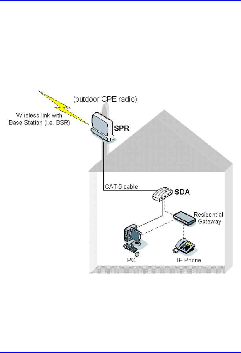
Figure 1-3 displays a typical subscriber site setup implementing an SPR and SDA.
Figure 1-3: Subscriber site with SPR and SDA units (optional RGW)

Overview Hardware Installation Guide
1-12 Airspan Networks Inc. 02030311-08
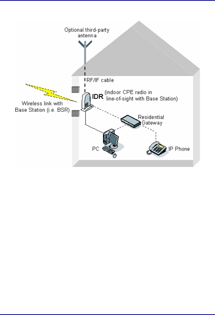
1.4.2. Indoor Radio Unit (IDR) Only
The indoor radio unit configuration consists of the ASWipLL Indoor Data Radio
(IDR). The IDR combines the functionality of the SPR and SDA, functioning as a
transceiver and a hub. The IDR provides one 10BaseT Ethernet interface to the
subscriber's network. The IDR receives its power from a separate power supply unit
(AC-DC power adapter).
The IDR with a built-in antenna is typically mounted on an interior wall or on a
desktop with line-of-site with the Base Station. The antenna of the IDR model with
an external antenna is typically mounted outdoors to provide line-of-site with the
Base Station.
The IDR can be used for data and voice transmissions. In the case of voice, the IDR
uses a third-party RGW to interface with the subscriber's IP phone. Figure 1-4
displays a typical setup for data and voice at a subscriber site implementing the IDR.
Hardware Installation Guide Overview
02030311-08 Airspan Networks Inc. 1-13
Figure 1-4: Subscriber site with IDR (optional third-party external antenna and RGW)
02030311-08 Airspan Networks Inc. 2-1
Safety Guidelines
This chapter outlines safety guidelines when installing the ASWipLL system.
Warning: The user and the installer should be aware that changes and
modifications not expressly approved by Airspan Networks could void the
user's authority to operate the equipment.
Warning: Never install equipment that is damaged.
Warning: Only qualified personnel should be allowed to install, replace, and
service the ASWipLL equipment.
2
Safety Guidelines Hardware Installation Guide
2-2 Airspan Networks Inc. 02030311-08
2.1. ASWipLL Radios and Third-Party External
Antennas
Warning: Do not connect and disconnect antennas while the power is on. This
can cause irreversible damage to the device.
Warning: The digital portion of the transceiver has been tested and found to
comply with the limits for a Class B digital device, pursuant to part 15 of the
FCC rules. These limits are designed to provide reasonable protection against
harmful interference in a residential installation. This equipment generates,
uses, and can radiate radio frequency energy and, if not installed and used in
accordance with the instructions, may cause harmful interference to radio
communications. However, there is no guarantee that interference will not
occur in a particular installation. If this equipment does cause harmful
interference to radio or television reception, which can be determined by
turning the equipment on and off, the user is encouraged to try correct the
interference by performing one or more of the following measures:
- Reorientate or relocate the receiving antenna
- Increase separation between the equipment and receiver
- Connect the equipment to an outlet on a circuit different from that to which
the receiver is connected
- Consult the dealer or an experienced radio/TV technician for help
Warnings:
1) The device cannot be sold retail, to the general public or by mail order. It
must be sold to dealers.
2) Installation must be controlled.
3) Installation must be performed by licensed professionals.
4) Installation requires special training.
Warning: The ASWipLL radio devices and antennas should be installed ONL
Y
by experienced installation professionals who are familiar with local building
and safety codes and, wherever applicable, are licensed by the appropriate
government regulatory authorities. Failure to do so may void Airspan's
ASWipLL product warranty and may expose the end user or the service
provider to legal and financial liabilities. Airspan and its resellers or distributors
are not liable for injury, damage or violation of regulations associated with the
installation of outdoor units or antennas.
Hardware Installation Guide Safety Guidelines
02030311-08 Airspan Networks Inc. 2-3
Warning: For unlicensed bands, it is the responsibility of the person installing
the ASWipLL system to ensure that when using the outdoor antenna kits in the
United States (or where FCC rules apply), that only those antennas certified
with the product are used. The use of any antenna other than those certified
with the product is expressly forbidden in accordance with FCC rules CFR47
part 15.204. The installer should configure the output power level of antennas
according to country regulations and per antenna type.
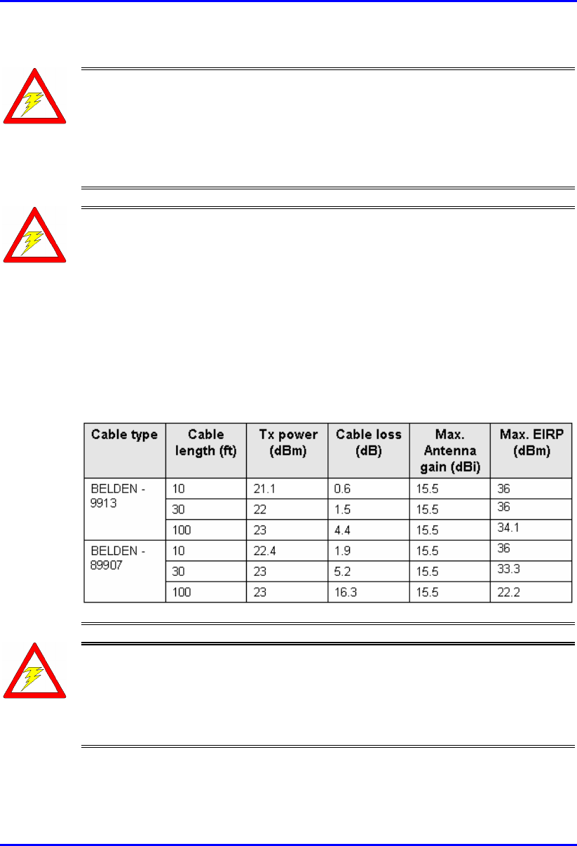
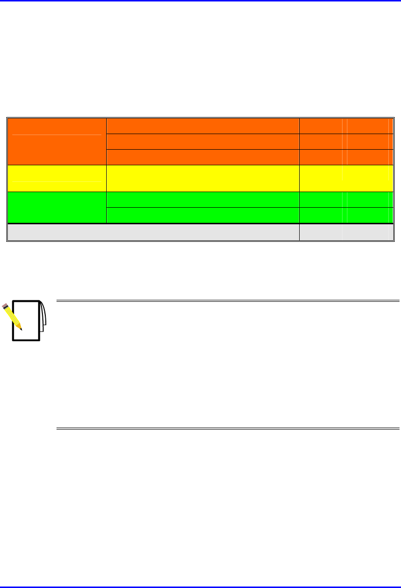
Warning: For unlicensed bands, in accordance with FCC regulations, ensure
that the external antennas provide an EIRP of less than or equal to 36 dBm to
prevent interference with other radios operating in the unlicensed band. The
EIRP is defined by the following formula:
Max. Power Output + Antenna Gain - Cable Loss ≤ 36 dBm (EIRP)
Airspan does not supply cables for connecting external antennas. It is the
responsibility of the installer to provide the cable and ensure the cable
characteristics (e.g. length and cable loss) enables adherence to FCC's
regulations concerning maximum EIRP.
The table below lists examples of cable loss per cable (not supplied by
Airspan) for maximum antenna gains, based on the formula above. Note that
the EIRP is either equal to or less than 36 dBm.
Warning: The ASWipLL radios emit microwave radiation. Therefore, a
minimum distance must be maintained from the front of the ASWipLL radios:
- Unlicensed bands (e.g. 5.8 GHz): 200 mm
- Licensed bands:
- 700 MHz (i.e. ASWipLL 700) = 800 mm
- 2.5 GHz (i.e. ASWipLL 2.5) = 500 mm

Safety Guidelines Hardware Installation Guide
2-4 Airspan Networks Inc. 02030311-08
Warning: To avoid RF interference between BSRs, ensure a minimum
1-meter horizontal separation between co-located BSRs.
Warning: To avoid RF interference between BSRs operating in the 700 MHz
where four BSRs are installed at a Base Station, in addition to 1-meter
horizontal separation, a minimum 1-meter vertical separation must be provided
between the two pairs of BSR antennas: one pair operating in the lower
frequencies (i.e. 711.5 and 714.5 for 1 Msps mode; 712 and 714 for 1.33 Msps
mode) and the other pair operating in the upper frequencies
(i.e. 741.5 and 744.5 for 1 Msps mode; 742 and 744 for 1.33 Msps mode).
Warning: When using external antennas, the external antennas must not be
co-located or operating in conjunction with any other antenna or transmitter.
Warning: ASWipLL radios using an external antenna(s) must not be co-
located or operating in conjunction with any other antenna or transmitter.
Warning: Inherent risks exist in operating equipment in license-exempt bands
(i.e. 900 MHz). Airspan recommends that you do not purchase or deploy any
equipment that operates in license-exempt bands without first analyzing the
interference environment at each of your proposed deployment locations.
Please contact your Authorized Airspan System Integrator or Distributor if you
have any questions or require assistance regarding interference analysis.
Airspan Networks will not be held responsible for product performance issues
related to interference.
Warning: In environments that produce disturbances such as paging systems,
Airspan recommends using a narrow-band cavity filter and implementing the
appropriate frequency bands (within the filter's capabilities), i.e. building an
NVRAM frequency table using only these frequencies.
Warning: Mount outdoor radios so that their front panel ports face down to
prevent water from settling on the ports. This avoids damage to the units such
as corrosion and electrical short-circuiting.
Warning: Do not mount outdoor radios and external antennas in weather such
as rain or lightening that may increase risk of electrocution.

Hardware Installation Guide Safety Guidelines
02030311-08 Airspan Networks Inc. 2-5
2.2. Electrical Safety Guidelines
Warning: Connect the power only after all network and antenna cable
connections are performed. Powering the device before connecting, fo
r
example, the external antenna, can lead to irreversible device damage.
Warning: To prevent short-circuiting and electrical shocks, cables with
exposed ends (i.e. not yet crimped) should be covered with protective
polythene bags during external cable installation processes.
2.2.1. Handling Electrostatic Devices
Warning: To prevent ESD damage to ASWipLL devices, always wear an ESD
wrist strap when handling these devices or coming into contact with internal
components.
Electrostatic devices are those devices that may be damaged by the inadvertent
discharge of static electricity from a charged body. The risk of damage, due to
electrostatic discharge (ESD) to a device, may cause the device to fail suddenly, or it
may induce a partial defect within the device, which will cause subsequent
premature failure. Static electricity can result from operators walking on floors,
moving around on chairs, from the movement of operator's clothing or even casual
brushing against racks, benches or walls.
Airspan recommends the following guidelines to be adopted to minimize the risk of
component failure due to electrostatic discharge to the device:
ASWipLL devices are provided typically in see-through anti-static bags.
Wherever possible, checking and inspection of a unit should occur without
removing it from the bag.
All operators shall wear the approved conductive overall.
Where operators come into direct contact with any piece of electronic hardware,
operators must wear an ESD-preventive wrist strap. All straps and cords
should be tested using a Wrist Strap Tester prior to use. The wrist strap cords
Safety Guidelines Hardware Installation Guide
2-6 Airspan Networks Inc. 02030311-08
shall have a 2 Meg Ohm resistor fitted at either end. Wrist straps should be worn
in direct contact with bare skin and not over clothing.
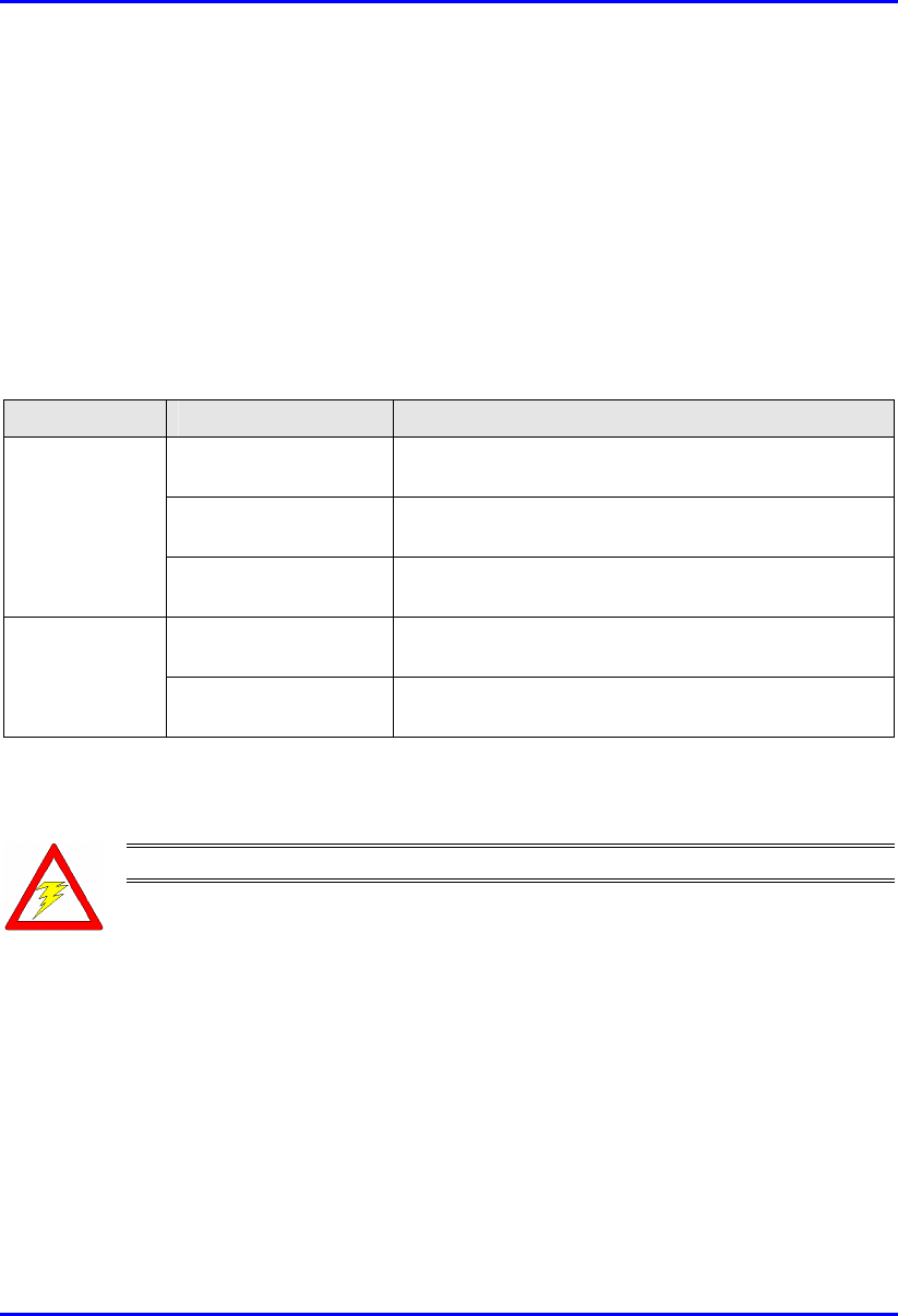
2.2.2. Grounding
Only certain ASWipLL devices require additional grounding. ASWipLL devices
that do not require additional grounding provide grounding at the main supply
outlet. The following table lists the ASWipLL devices' grounding requirements.
Table 2-1: ASWipLL grounding requirements
Site ASWipLL device Grounding
BSR Through the mains (via BSDU), i.e. no additional
grounding required
BSDU Additional grounding required (grounding lug at rear
end of chassis)
Base Station
BSPS (third-party) Additional grounding required (grounding lug at rear
end of chassis)
SPR Through the mains (via SDA), i.e. no additional
grounding required
CPE
IDR Through the mains, i.e. no additional grounding
required
2.2.3. Lightning Protection
Warning: Never install the equipment during stormy weather and lightning.
ASWipLL devices comply with the Surge Immunity standard: EN 61000-4-5.
ASWipLL devices are protected from lightning surges as the outdoor devices (BSRs
and SPRs) are encased in a plastic covering. Therefore, if lightning strikes the
device, an electrical circuit cannot be completed, and hence, no electrical surge can
occur.
In addition, ASWipLL outdoor and indoor (i.e. SDA) devices provide high-speed
data line protection against direct and induced transient over-voltage surges on the
cables. This capability is provided by the fact that all ASWipLL devices are
Hardware Installation Guide Safety Guidelines
02030311-08 Airspan Networks Inc. 2-7
designed with transient voltage suppressor (TVS) components that maintain
potential differences.
However, in geographical areas that have above normal lightning activity, Airspan
can supply an optional DC surge protector adapter (see Part II, Chapter 18, "Power
Cabling").
2.3. Cabling
Warning: The maximum cable length between the radio transmitters (i.e. BSR
and SPR) and terminating equipment is 100 meters.
Warning: Cables with exposed ends (i.e. not yet crimped) should be covered
with protective polythene bags during external cable installation processes.
Warning: Disturbance of cables on an In-Service exchange can cause loss o
f
service. Extreme care must be taken when installing cables at any customer o
r
subscriber premises.
2.3.1. Considerations
The following issues should be considered during cabling at the ASWipLL Base
Station and customer premises:
Cable routes are to be defined in a site-specific documentation.
Note: A minimum separation of 200 mm should exist between power and data
cables. However, it is permissible to allow these cables to cross each other a
t
right angles.
Observe recommended minimum bend radii when installing copper cables.
Wherever a cable changes direction, ensure that it does so in a smooth curve
with a radius of at least 50 mm to prevent damage.
Plastic ties and wraps are to be used to secure cables at regular intervals to trays,
guides, and mounting pole/bracket. Ensure all trimmed ends are disposed of
safely and at regular intervals.

Safety Guidelines Hardware Installation Guide
2-8 Airspan Networks Inc. 02030311-08
Data cables of less than 20 pairs shall be mixed in bundles not exceeding 50 mm
in diameter.
Ensure cables are not trapped in cabinet doors, by slide-in equipment or support
metalwork.
Excessive stress on cable terminations caused by taught cables should be
avoided. Connector strain relief, if not built into the connector used, shall be
provided by means of a strategically located cable tie. A maintenance loop or a
generous amount of cable slack shall be provided just before the cable reaches
the ASWipLL device to allow for equipment removal without disturbance to
adjacent cables.
When installing network cables, ensure they are not damaged by friction or sharp
edges.
Data cables providing connection to the customers network shall be run in
protective conduits. Cable conduits should be secured to the wall in accordance
with manufacturers instructions.
External data cables are to be protected in metal conduits, which are to be
secured to the building structure in accordance with manufacturers
recommendations.
Wiring conduits must be placed in areas to prevent a trip hazard (e.g. don't install
on roof walkways)
Cables should be carefully fed through conduits and not pulled by means of any
attached connector.
Sufficient space should be provided in cable conduits, trunking or trays (where
possible) to allow for future cabling growth.
Data cables threaded into holes drilled in walls are to be covered by a waterproof
sheath to prevent water penetration.
Silicone sealant should be used to plug any holes on both internal and external
wall surfaces once cables are in place.
Cables not housed in conduits must be placed in a manner to avoid a trip hazard.
(Avoid trailing wires across passageways.)

Hardware Installation Guide Safety Guidelines
02030311-08 Airspan Networks Inc. 2-9
2.3.2. Labeling
The following labels are required to be fitted to ASWipLL equipment:
Voltage Warning
High Earth Leakage Current
Signal Cable Designation
2.3.2.1. Voltage Warning
Warning: Voltages over 30 Volts AC and 50 Volts DC are categorized as
hazardous. Hazard warning labels should be fitted where required. Certain
countries require equipment warning and instruction labels to appear in the
local language. When installing ASWipLL equipment ensure that local
requirements regarding labels are given consideration.
Where mains power is fed from separate phases, appropriate warning labels must
be fitted to warn of the increased danger.
The AC equipment used in the BSPS cabinet must carry a relevant voltage
warning label specific to the country in which it is being installed. The label will
be fitted to the cabinet doors displaying an electrical hazard symbol, the local
operating voltage and the letters 'AC'.
A power feed identification label (e.g. PWR 'A') shall be applied in the following
locations:
On the rear of the main power rack adjacent to the terminal block
Attached to BSPS AC mains power plug or lead
Attached to the customer mains power socket or distribution rail
On the BSPS power circuit connection at the fuse board

Safety Guidelines Hardware Installation Guide
2-10 Airspan Networks Inc. 02030311-08
2.3.2.2. High Earth Leakage Current
If equipment earth leakage current exceeds 3.5 mA, a warning label as shown in
Figure 2-1 must be fitted to the rear of the main power rack alongside the AC inlet
terminal block.
Figure 2-1: Warning label if earth leakage current exceeds 3.5 mA
2.3.2.3. Signal Cable Designation
All data cables should be labeled with both the source and destination at each end. A
wrap around identification label is to be fitted to both ends of ASWipLL data cables.
Care should be taken to ensure that the cable identification information is clearly
visible. Fit the label 100 mm from the cable end. Wrap the label ensuring good
adhesion to cable and itself.
WARNING
HIGH LEAKAGE CURRENT
Earth connection essential
Before connecting supply

02030311-08 Airspan Networks Inc. 5-1
Radio Site Planning
Proper site selection and planning before installing your ASWipLL devices will
ensure a successful deployment of your ASWipLL system. Site planning includes
the following considerations:
Minimum obstructions (e.g. buildings) in the radio path between Base Station
radio (i.e. BSR) and subscriber radios (i.e. SPR/IDR).
Minimum incursions on Fresnel Zone (recommended minimum of 60%
clearance of first Fresnel Zone).
Mount radios as high as possible to avoid obstructions in the wireless path.
Check possibility of future obstructions such as plans to erect buildings and trees
that may grow tall enough to obstruct the wireless path.
Align antennas for maximizing received signal strength (RSS)
Consider nearby sources of interference that could degrade performance of radio.
Mount radios as far from sources of interference as possible
Ensure Base Station radio and subscriber premise's radio are within maximum
coverage range of reception
Maximum CAT-5 cable length connecting the outdoor radio to the indoor
terminating equipment (i.e. switch/hub) is 100 meters
Ensure that you have sufficient wiring conduit and cable ties to channel and
protect the CAT 5 cable connecting the outdoor radio to the indoor hub/switch.
Ensure required power mains outlet is available at the site.
5
Radio Site Planning Hardware Installation Guide
5-2 Airspan Networks Inc. 02030311-08
5.1. Minimal Radio Path Obstructions
ASWipLL radios communicate by propagation of waves. Thus, ensure minimum
obstructions (from, e.g. buildings and trees) in the radio path between Base Station
radio (i.e. BSR) and subscriber radios (i.e. SPR/IDR). It is essential that the
ASWipLL radios or antennas be installed in such a way that their radio paths have a
clear path with each other.
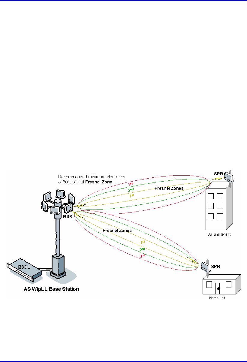
5.2. Fresnel Zone Clearance
There must be sufficient open space around the radio path to minimize interference
with the radio beam. A minimum of 60% of the first Fresnel Zone of the path
should be clear of obstructions. Despite a clear line-of-site, objects close enough to
the transmission path may cause attenuation in signal strength and an increase in
signal interference. Objects with reflective surfaces that seem relatively far away,
but yet still encroaching on Fresnel Zone, may cause these interferences.
Figure 5-1: At least 60% of first Fresznel Zone should be clear
Fresnel Zones define the amount of clearance required from obstacles. These zones
are composed of concentric ellipsoid areas surrounding the straight-line path

Hardware Installation Guide Radio Site Planning
02030311-08 Airspan Networks Inc. 5-3
between two antennas. Thus, the zone affects objects to the side of the path and
those directly in the path. The first Fresnel Zone is the surface containing every
point for which the distance from the transmitter to any reflection point on the
surface point and then onto the receiver is one-half wavelength longer than the direct
signal path.
One method for clearing the Fresnel Zone (to use the free space model to calculate
link budget – see Section 5.6, "Calculating Link Budget") is by increasing the
antenna height.
The first Fresnel Zone radius is calculated by the following equation:
Where f is the frequency (in MHz) and d is the distance (in meters).
For example, using the formula above, a link of 4 km at 700 MHz produces a first
Fresnel Zone radius clearance of about 20 meters. This implies that to ensure the
ground does not enter into the first Fresnel Zone, both antennas (i.e. at Base Station
and subscriber) must be mounted at least 20 meters above ground level (or clutter
level). Typically, at least 60% clearance of the first Fresnel Zone is considered as
LOS. Therefore, in the above example, a height of at least 12 meters (i.e. 60% of 20
meters) above ground level is sufficient for LOS.
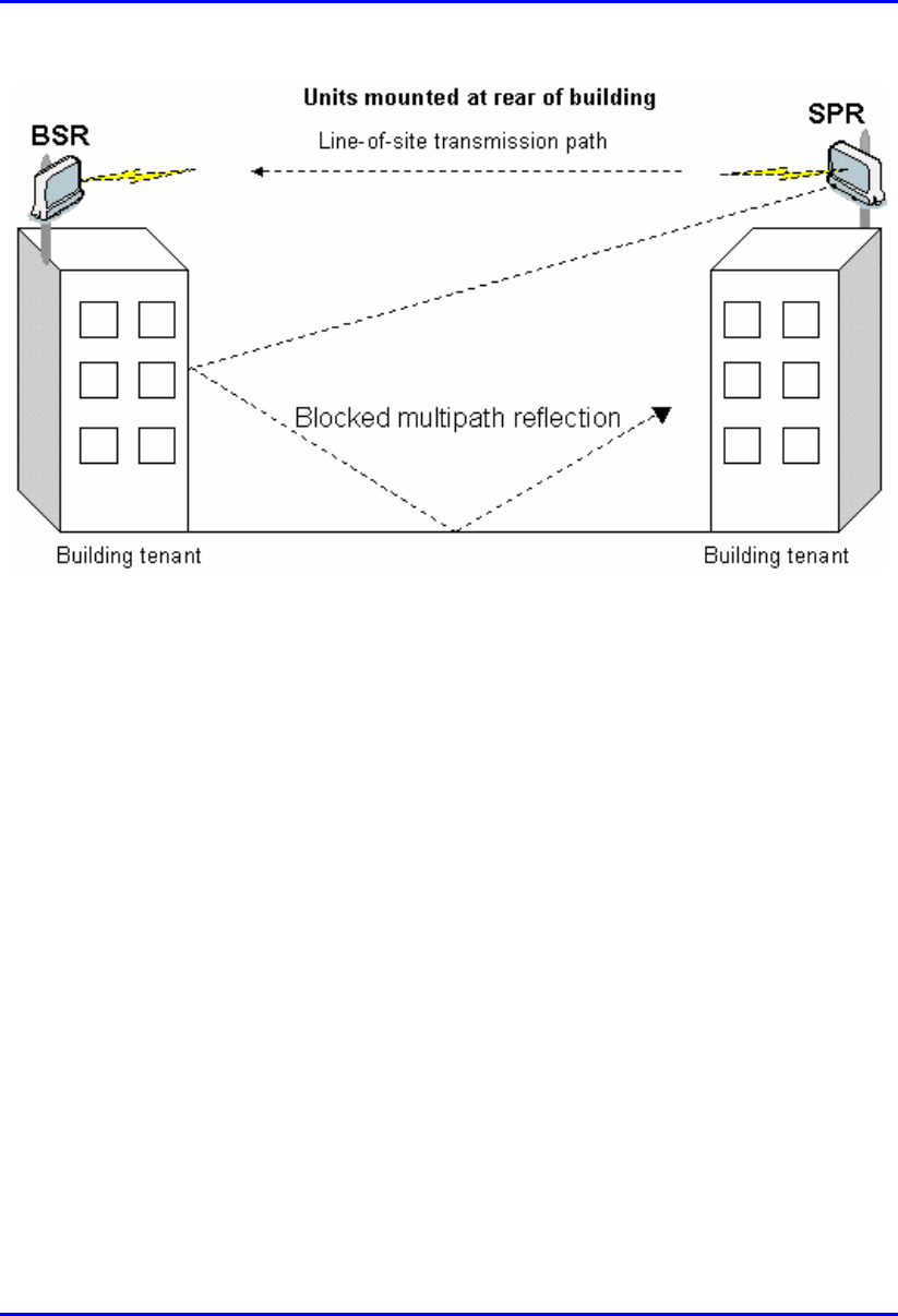
5.3. Multipath Fading
Some of the transmitted signals may be reflected from a nearby building, by water
under the signal path, or from any other reflectors. This reflected ("bounced") signal
can then be received by the radio receiving the signal and superimposed on the main
received signal, thereby degrading the signal strength.
To avoid multipath fading from nearby buildings etc., Airspan recommends
installing the outdoor radios at the rear end of the buildings instead of at the front.
When you install at the rear end of the building, the front-end of the building blocks
incoming signals from multipath reflections.
Radio Site Planning Hardware Installation Guide
5-4 Airspan Networks Inc. 02030311-08
Figure 5-2: Radios mounted at rear, blocking multipath reflection
5.4. Spectrum Analysis for Locating Clear
Frequencies
Before setting up your wireless link between Base Station and subscribers, Airspan
recommends (especially in unlicensed bands), analyzing the RF spectrum at the
Base Station to select only clear frequency channels (i.e. without interferences) for
building a frequency table for wireless communication between Base Station and
subscriber.
Prior to performing this test, you need to mount the radio/antenna in the desired
installation spot. In general, you will be looking for frequencies with signal strengths
of –85 dBm or greater.
For using Airspan's spectrum analyzer tool, refer to the WipConfig User's Guide. For
evaluating link quality using the Spectrum Analyzer, see Appendix F, "Evaluating
Link Quality".

Hardware Installation Guide Radio Site Planning
02030311-08 Airspan Networks Inc. 5-5
5.5. Adjacent Base Station Radios
For installations involving co-location of BSRs, it is important to assign frequencies
of maximum spacing. This is to reduce possible radio interference between
adjacently installed BSRs. In addition, a 1-meter separation must exist between
adjacent BSRs.
5.6. Calculating Link Budget
Link budget is the computation of the maximal achievable reception level for the
communication link between the Base Station and the subscriber site. This level is
the minimum required received signal level (RSS) at the antenna port for the radio to
close the communication link at a given data rate and under the worst-case fading
channel. This level must be greater or equal to the radio's receiver sensitivity, which
is the minimum RF signal power level required at the input of a receiver for certain
performance (e.g. > BER).
This takes into account the following aparameters:
Transmit (dBm) EIRP:
Tx transmitter power (dBm) - cable loss (dB) + Tx antenna gain (dBi)
Propagation (dB):
Free space loss (dB) = 32.44 + 20logd(km) + 20logf(MHz), where f is the
frequency in MHz, and d is the distance between transmitting and receiving
radios in km.
Note: Free space propagation loss is valid when the first Fresnel Zone is clear.
Receive (dBm):
Rx antenna gain (dBi) - cable loss (dB)
The formual to calculate receive signal power:
Rx = Tx EIRP – (path loss) + receive (i.e. Tx gain – Tx cable loss)
Radio Site Planning Hardware Installation Guide
5-6 Airspan Networks Inc. 02030311-08
The Rx value must be higher than the receiver sensitivity for communication link to
succeed.
Example: Frequency =2.4 GHz; Tx power output = 27 dBm; Tx and Rx cable loss =
0 dB; Tx antenna gain = 11 dBi; Rx antenna gain = 15 dBi; distance between sites =
6 km; Receiver sensitivity = -75 dBm.
Transmit output power 27 dBm
Cable loss (negative value) 0 dB
Transmit
Antenna gain 11 dBi
Propagation Free space loss (negative value)
32.44 + 20log(6 km) + 20log(2400 MHz)
-116 dB
Antenna gain 15 dBi
Receive
Cable loss (negative value) 0 dB
Minimal received signal Rx = -63 dBi
Therefore, received signal power is EIRP – path loss + receive = 38 dBm – 116 dB +
15 dBi = -63 dBm. In conclusion, the received signal power is above the device's
sensitivity threshold (-75); thus a communication link should succeed.
Notes:
1) ASWipLL can operate in 2-, 4-, and 8-level FSK with signal strengths (i.e.
receiver sensitivity) of greater than -90, -83, and -75 dBm, respectively.
2) These link budget rules are theoretical. It represents the maximum
achievable for a system. In reality we have interferences (other WLAN
networks, bluetooth), industrial noise (microwave ovens), atmospheric losses
(air moisture, scattering, refraction), badly pointed antenna, reflexions,... that
will affect performances. Thus, It is necessary to take a sufficient security
margin on large distances.
3) Normally, a higher margin is desirable due to fluctuation in received power
as a result of signal fading.
5.7. Radio Antenna Alignment
Once the subscriber unit (i.e. SPR/IDR) is installed and aimed in the general
direction of the BSR, it is recommended to measure the received signal strength

Hardware Installation Guide Radio Site Planning
02030311-08 Airspan Networks Inc. 5-7
(RSS) to determine the signal strength received from the BSR, and to precisely align
the SPR/IDR for maximum signal strength.
You need to orientate (up/down, left/right) the SPR/IDR until the maximum RSSI
levels are achieved, and then secure the SPR/IDR. For short links you can expect an
RSSI of –60 dBm or better. For longer links, an RSSI of –75 dBm is acceptable.
Any RSSI of less than –80 dBm may be too weak for the radios to reliably
communicate.
Airspan offers various tools for measuring RSS (check with your Airspan
representative regarding cost and supply):
SPR:
RSS LED adapter (see Part II, Chapter 17, "Antenna Alignment using RSS
LED Adapter")
WipConfig program (see Appendix F, "Evaluating Link Quality")
IDR: built-in RSSI LEDs (see Part III, Chapter 24, " Antenna Alignment Using
RSS LEDs")
5.8. Considerations when Using External
Antennas
Notes:
1) To avoid unnecessary RF cable loss, use short-length cables and with low
attenuation.
2) Antennas should have a VSWR of less than 1:1.5.
3) Ensure BSR and SPR/IDR use the same antenna polarity.
4) When using an omni-directional antenna, choose a type providing a wide
vertical beam width (of at least 8°) to allow connection of closer CPEs.
5) Antenna must be DC grounded.
5.8.1. Cable Loss
Airspan's ASWipLL radios provide transmit power compensation for power
attenuation caused by cable loss (in cable connecting to external antenna). Cable loss

Radio Site Planning Hardware Installation Guide
5-8 Airspan Networks Inc. 02030311-08
is the loss of radio transmit (Tx) power as heat, and directly proportional to cable
length and quality, and operating frequency.
Hardware Installation Guide Radio Site Planning
02030311-08 Airspan Networks Inc. 5-9
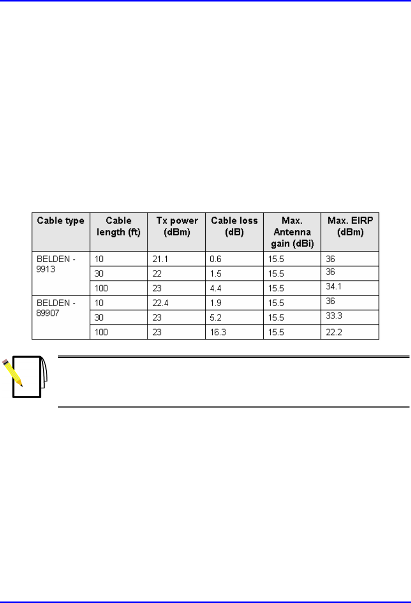
To adhere to Effective Isotropic Radiated Power (EIRP) limitations in the regulatory
domain (country) in which you are operating your ASWipLL system, when
purchasing antenna cables, take into consideration cable loss per cable length. EIRP
is calculated using cable loss (i.e. EIRP = max. transmitter power output + antenna
gain - cable loss). For example, FCC regulations state that when operating in
unlicensed bands, the external antennas must provide an EIRP of less than or equal
to 36 dBm to prevent interference with other radios. Thus, knowing this EIRP
parameter, you can choose the cable that ensures adherence to this parameter value.
The table below lists examples of cable loss per cable length.
Table 5-1: Examples of cable loss per cable length
Note: Airspan does not supply external antenna cables. It is the responsibility
of the installer to provide the cable and ensure the cable characteristics (e.g.
length and cable loss) enables adherence to EIRP regulations of the country or
area in which the ASWipLL system is operating.

Radio Site Planning Hardware Installation Guide
5-10 Airspan Networks Inc. 02030311-08
5.8.2. Omni-Directional Antennas
In some scenarios, where capacity demand is relatively low, external omni-
directional antenna use at the Base Station may seem attractive. However, it is
recommended to avoid using omni-directional antennas (if possible), due to the
following disadvantages that these antennas pose compared to directional antennas:
Higher sensitivity to external interferences.
Higher sensitivity to multipath, resulting in the following:
The root mean square (RMS) delay spread at the Base Station is substantially
higher.
Multipath interference at the CPE side (when using omni-directional antenna
at the Base Station) is substantially higher. In fact, when using an omni-
directional antenna, the existence of clear Fresnel zone between BSR and
SPR/IDR is insufficient to eliminate multipath interference, since multipath,
in this case, can be caused by reflections originating from obstacles outside
the Fresnel zone.
Higher sensitivity to alignment. Since the omni-directional antenna gain is
achieved by narrowing the vertical beam width, a relatively low deviation in the
antenna alignment will result in severe signal attenuation.
5.8.3. Operating in 900 MHz
The performance of ASWipLL 900 operating in the 900 MHz band, may vary
dramatically depending on the polarization of antennas, i.e. vertical or horizontal.
Therefore, it is recommended that the operator, during installation, compare the
performance between horizontal and vertical polarization of external antennas, and
use the polarization providing the best performance.
Note: Some antennas support both horizontal and vertical polarization:
- Yagi
- 9 dBi antenna (Cat. No. 35000008)
- 6.5 dBi antenna (Cat. No. 35000009)
Hardware Installation Guide Radio Site Planning
02030311-08 Airspan Networks Inc. 5-11
5.8.4. Operating in Band-C for FCC Markets
Some operators (e.g. in the USA) have licenses for Band-C (710 – 716 MHz and 740
– 746 MHz). ASWipLL 700 provides an external antenna, allowing coverage in the
entire 700 MHz band (698 to 746 MHz), including the licensed A and B bands used
in USA.
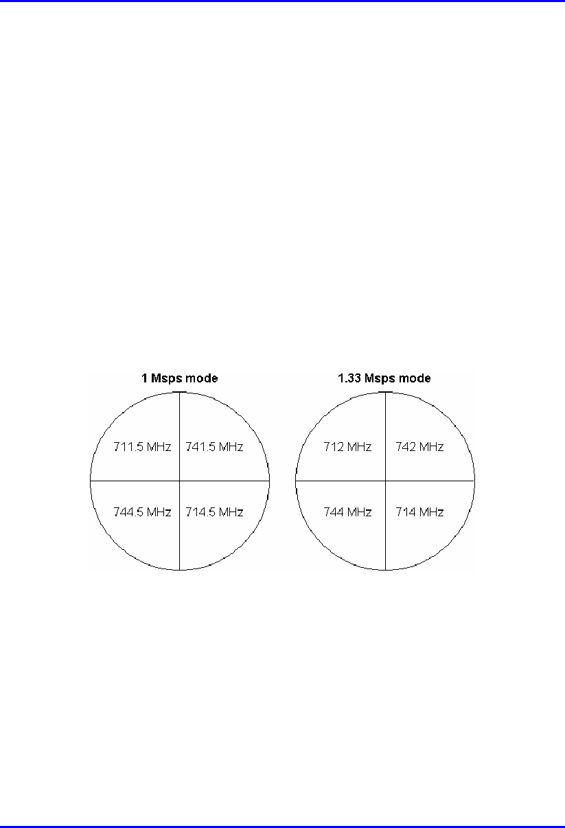
A maximum of four BSRs operating in Band-C are allowed at a Base Station (in
accordance with FCC regulations). This regulation ensures minimum RF
interference with other radio devices that may be operating in nearby frequencies.
In the 1 Megasymbols per second (Msps) mode, the center frequencies are 711.5,
712.5, 713.5, 714.5, 741.5, 742.5, 743.5, and 744.5. Thus, the frequency allocation
for four BSRs is 711.5, 741.5, 714.5, and 744.5.
In the 1.33 Msps mode, the center frequencies are 712, 713, 714, 742, 743, and 744.
Thus, the frequency allocation for four BSRs is 712, 742, 714, and 744.
Figure 5-3: Frequency allocation in a four-sector Base Station
Radio interference may occur between the BSRs operating in the upper frequency
range (i.e. 742 MHz and 744 MHz) and the lower frequency range (i.e. 712 MHz
and 714 MHz). To overcome this interference, a 1-meter vertical separation (in
addition to the general 1-meter horizontal separation) is recommended between the
BSRs operating in the upper frequency and the BSRs operating in the lower
frequency.

Radio Site Planning Hardware Installation Guide
5-12 Airspan Networks Inc. 02030311-08
5.8.5. Dual Antenna Receive Diversity
For BSRs operating in the 700 MHz or 900 MHz bands, two antennas are provided
for antenna receive diversity at the ASWipLL Base Station. This allows the BSR to
select the antenna providing the best RF reception to receive the signal.
In this operating band, for BSR models with integral antennas, two internal, built-in
antennas are provided. For BSR models without built-in, internal antennas, dual
diversity is provided by the existence of two N-type connectors for attaching two
external antennas.
Notes:
1) The BSR with two antennas transmits using only one of the antennas
(factory selected).
2) Antennas must be orientated to cover the same area/cell (i.e. subscriber
sites), from only a slightly different location.

02030311-08 Airspan Networks Inc. 6-1
Basic Design of Devices
This chapter describes the basic design of the ASWipLL devices that can be
installed at the Base Station:
BSR
BSDU
SDA-1/48V
GPS
BSPS
6.1. BSR
The BSR is an encased outdoor radio providing access to the BSR's communication
ports on its front panel. The BSR's bottom panel provides holes for mounting the
BSR to, for example, a pole or wall.
6.1.1. Models
The BSR is available in the following basic physical designs:
BSR with a built-in, internal antenna
BSR with an N-type port for connecting an optional third-party external antenna
BSR with two N-type ports for connecting two optional third-party external
antennas for dual antenna diversity (when operating in the 700 or 900 MHz
bands)
6

Basic Design of Devices Hardware Installation Guide
6-2 Airspan Networks Inc. 02030311-08
The table below provides a brief description of the BSR models and the frequencies
in which they can operate. For a detailed description of the BSR products, see
Appendix I, "ASWipLL Product List".
Table 6-1: Operating frequency ranges per BSR model
BSR model Operating frequency (MHz) Antenna configuration
BSR 700 698 to 746 Internal or external (up to two
external antennas)
BSR 900 902 to 928 Internal or external (up to two
external antennas)
BSR 925 910 to 940 External
BSR 1.5 1,427 to 1,525 Internal or external
BSR 2.3 2,300 to 2,400 Internal or external
BSR 2.4 2,400 to 2,500 Internal or external
BSR MMDS 2,500 to 2,686 Internal or external
BSR 2.8 2,700 to 2,900 Internal or external
BSR 3.x 3,300 to 3,810 Internal or external
BSR 5.8 5,725 to 5,875 Internal or external
Notes:
1) BSR device with an N-type port(s) for attaching a third-party external
antenna(s) do not provide a built-in antenna.
2) The BSR installation procedures described in this guide apply to all BSR
models, except the procedures for attaching third-party external antennas
(which apply only to BSR models providing an N-type port).
6.1.2. Physical Dimensions
The BSR's physical dimensions are described in the table below.
Table 6-2: BSR physical dimensions
Parameter Value Comment
Height 400 mm (15.74 inches) The BSR's physical dimensions
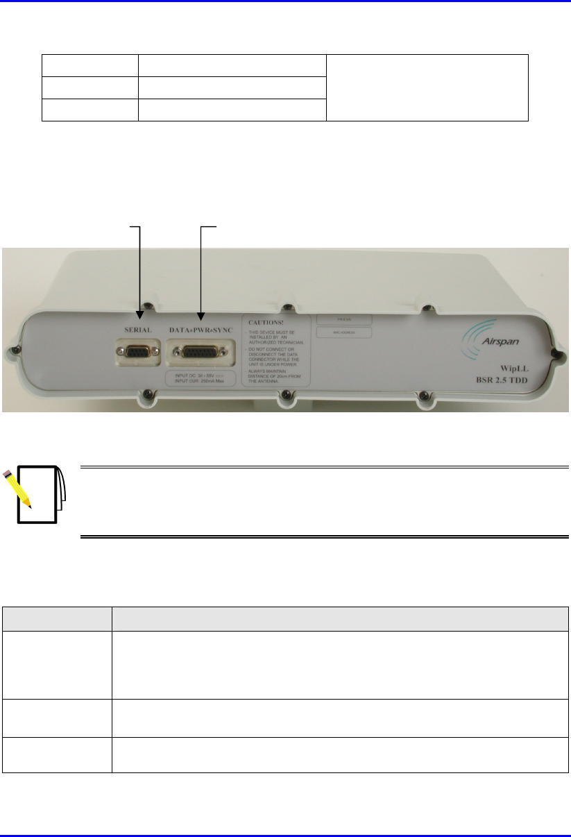
Hardware Installation Guide Basic Design of Devices
02030311-08 Airspan Networks Inc. 6-3
Width 317 mm (12.48 inches)
Depth 65.5 mm (2.58 inches)
Weight 4.7 kg
exclude the mounting kit
6.1.3. Ports
The BSR provides various ports on its front panel, as displayed below:
Figure 6-1: BSR front panel (built-in antenna model)
Note: BSR models that use third-party external antennas provide an N-type
female receptacle for attaching an external antenna. In addition, BSR models
operating in the 700 and 900 MHz bands provide two N-type receptacles fo
r
dual antenna receive diversity.
The table below describes the BSR ports.
Table 6-3: BSR ports
Port Interface
15-pin D-type • Ethernet (10BaseT): with the BSDU (or SDA)
• Synchronization: of BSRs controlled by BSDU
• Power: supplied by BSDU (or SDA)
9-pin D-type Serial (RS-232) local initial configuration (using WipConfig tool) during
installation
N-type (Depends on model). For attaching third-party external antennas. BSR models
for the 700 and 900 MHz bands provide two N-type ports. BSR models with
9-pin D-type por
t
15-pin D-type port

Basic Design of Devices Hardware Installation Guide
6-4 Airspan Networks Inc. 02030311-08
built-in antennas do not provide N-type ports.
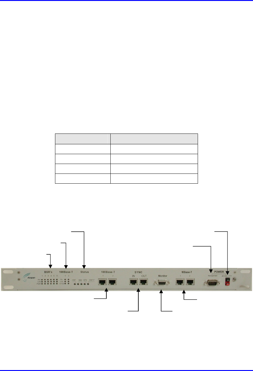
Hardware Installation Guide Basic Design of Devices
02030311-08 Airspan Networks Inc. 6-5
6.2. BSDU
The BSDU is an Ethernet switch encased in a chassis providing access to the
BSDU's communication ports on the front and rear panels. The BSDU is installed in
a standard 19-inch rack.
6.2.1. Physical Dimensions
The BSDU's physical dimensions are described in the table below.
Table 6-4: BSDU physical dimensions
Parameter Value
Height 43.2 mm (1.7 inches)
Width 482.6 mm (19 inches)
Depth 228.6 mm (9 inches)
Weight 2.9 kg
6.2.2. Ports
The BSDU (displayed below) provides ports on the front and rear panels.
Figure 6-2: BSDU front panel
BSR's LEDs
100Base-T LEDs
Status LEDs Power receptacle
BSPS power
management port
10BaseT ports
Serial port Synchronization ports
100BaseT ports
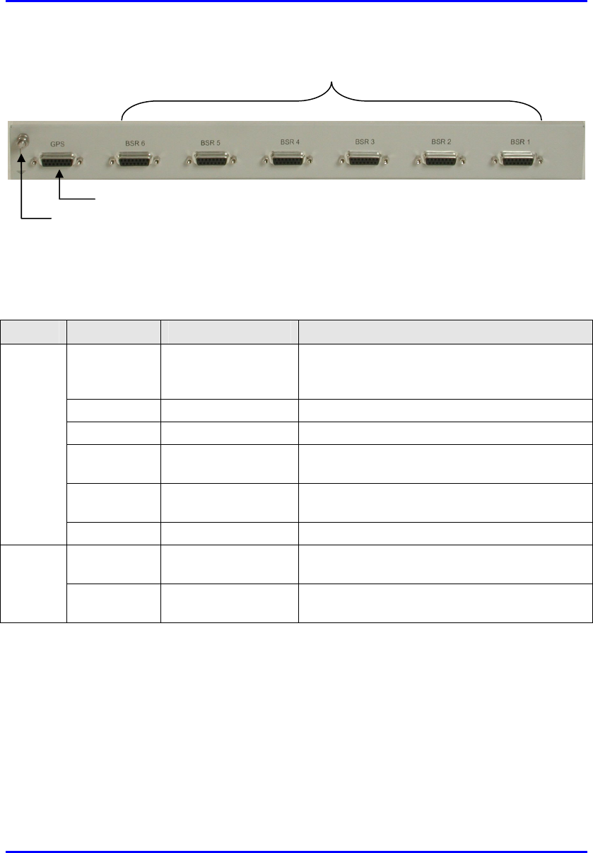
Basic Design of Devices Hardware Installation Guide
6-6 Airspan Networks Inc. 02030311-08
Figure 6-3: BSDU rear panel
The table below describes the BSDU's ports on the front and rear panels.
Table 6-5: List of BSDU ports
Panel Label Port Interface
100Base-T RJ-45 (two) 100BaseT interface with provider's backbone
(WAN), and for BSDU and BSRs management
interface (if 10Base-T ports are looped)
SYNC RJ-45 (two) Synchronization between BSDUs
Monitor 9-pin D-type female BSDU serial interface
10Base-T RJ-45 (two) BSDU management (port #2) and management
to BSRs connected to BSDU (port #1)
Management 9-pin D-type male Base Station Power System (BSPS) remote
management interface using WipManage
Front
48 VDC Power receptacle Connecting DC power supply from, e.g. BSPS
GPS 15-pin D-type Connecting a Global Positioning System (GPS)
antenna for synchronization
Rear
BSR 15-pin D-type (six) Interfacing with BSRs, providing BSRs with DC
power, Ethernet connection, and synchronization
A 5-mm diameter-grounding lug is present on the rear panel for grounding the
BSDU.
6.2.3. LED Indicators
The BSDU provides various LED indicators located on the BSDU's front panel (see
Figure 6-2). These LEDs are grouped under the following labels:
15-pin D-type ports for BSRs
15-pin D-type for GPS
Grounding lug

Hardware Installation Guide Basic Design of Devices
02030311-08 Airspan Networks Inc. 6-7
BSR's
100Base-T
Status
6.2.3.1. BSR's LEDs
The BSR's LED indicators provide three LEDs for each of the six BSR ports. These
LEDs are described in Table 6-6.
Table 6-6: BSR's LED description
LED Color Status Meaning
On Ethernet activity is detected on the BSR port
Act Yellow
Off No Ethernet activity detected on the BSR port
On Physical link exists between the BSDU and BSR
Link Yellow
Off No physical link exists between the BSDU and BSR
On Power is supplied to the BSDU's BSR port
PWR Yellow
Off No power is available, or the BSDU's BSR port is disabled by
software, or port failure has occurred
6.2.3.2. 100Base-T LEDs
The 100Base-T LED indicators provide three LEDs for each of the two 100Base-T
ports. These LEDs are described in Table 6-7.
Table 6-7: 100Base-T LED Description
LED Color Status Meaning
On Data is received through the 100Base-T port
Rx Yellow
Off No data is received through the 100Base-T port
On Viable physical link between the 100Base-T port and the
external device to which this port connects
Link Yellow
Off No physical link between the 100Base-T port and the external
device to which this port connects
On Power is supplied to the 100Base-T port
10/100 Yellow
Off No power at the 100Base-T port

Basic Design of Devices Hardware Installation Guide
6-8 Airspan Networks Inc. 02030311-08
6.2.3.3. Status LEDs
The Status LEDs indicate various synchronization and GPS functioning, as
described in the table below.
Table 6-8: Status LED Description
LED Color Status Meaning
HSP (Hop
Synchronization
Process)
Green On BSDU synchronization process is
active
Only right LED is on Synchronization process is starting
Both LEDs are on BSDU is the master unit
Only left LED is on BSDU is a slave unit
State (two LEDs) Green
Both LEDs are off BSDU synchronization pulse lost
(i.e. no synchronization)
On GPS antenna is connected to the
BSDU
GPS Green
Blinking Receiving a satellite signal via GPS
HSP P (Hop
Synchronization
Process Pulse)
Green On Change state for the HSP pulse
6.3. SDA-1/48V
The SDA-1/48V is a compact indoor adapter especially designed for use when
available power source is 48VDC (i.e. no AC power supply), and when no
synchronization is required (i.e. in licensed bands). The SDA-1/48V connects to the
BSR by a standard CAT 5 cable, providing Etherent and power interfaces.
6.3.1. Physical Dimensions
The SDA-1/48V physical dimensions are described in the table below.
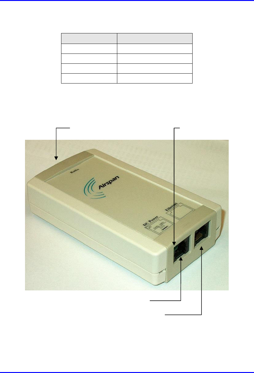
Hardware Installation Guide Basic Design of Devices
02030311-08 Airspan Networks Inc. 6-9
Table 6-9: SDA-1/48V physical dimensions
Parameter Dimensions
Height 123 mm (4.84 inches)
Width 68 mm (2.68 inches)
Depth 30 mm (1.18 inches)
Weight 85g
6.3.2. Ports
The SDA-1/48V provides various port interfaces as displayed in Figure 6-4.
Figure 6-4: SDA-1/48V ports
RJ-11 DC power port
RJ-45 Ethernet port
15-pin D-type port (Radio) Power LED

Basic Design of Devices Hardware Installation Guide
6-10 Airspan Networks Inc. 02030311-08
The table below describes the SDA-1/48V port interfaces.
Table 6-10: Description of SDA-1/48V ports
Port Interface
15-pin D-type Interfaces with ASWipLL outdoor radio (i.e. BSR, PPR, or SPR) by a CAT 5
cable
8-pin RJ-45 10BaseT interface with, for example, a router, backhaul solutions, a LAN
switch, a PC
6-pin RJ-11 Power (including power LED)
6.3.3. LED Indicators
The SDA-1/48V provides a power LED that indicates whether or not the
SDA-1/48V is receiving power. This LED is located in the top-left corner of the RJ-
11 port (labeled DC Power).
When power is received by the SDA-1/48V, the power LED is lit (green color).
When no power is received, the power LED is off.
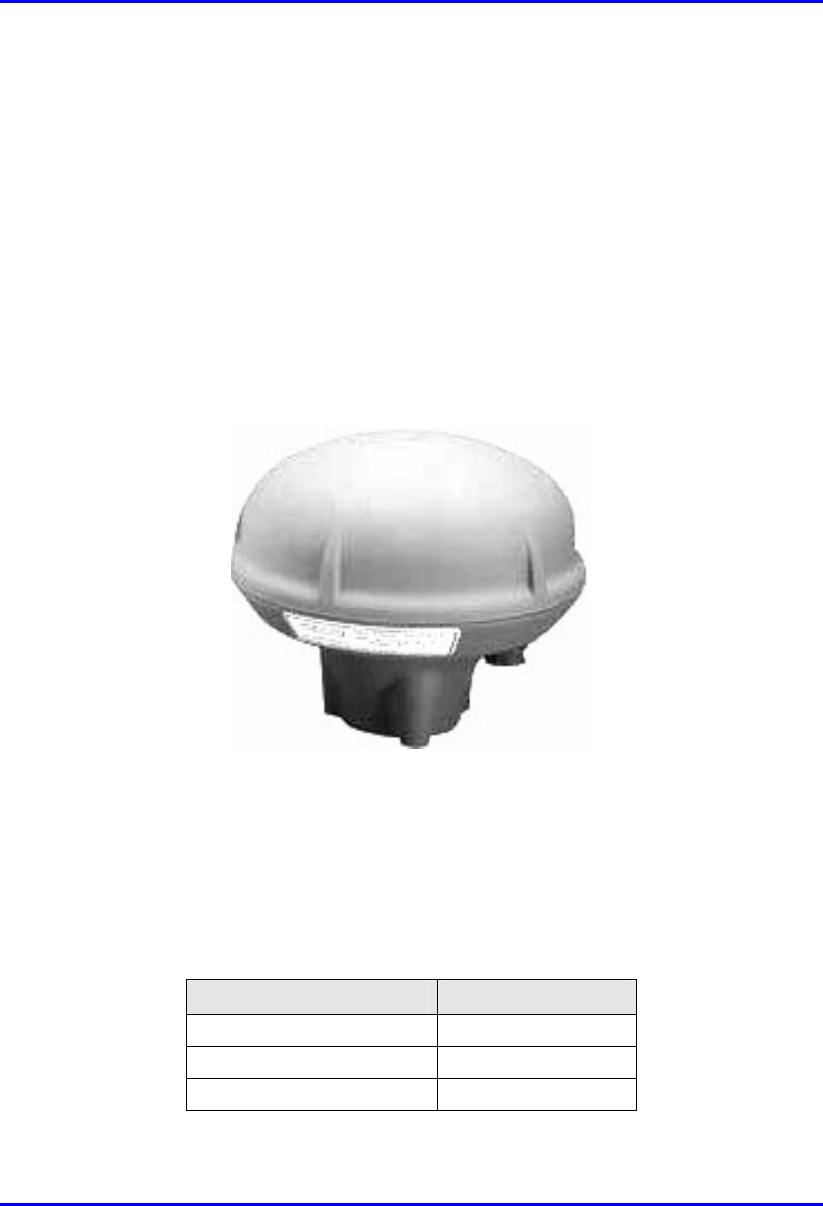
Hardware Installation Guide Basic Design of Devices
02030311-08 Airspan Networks Inc. 6-11
6.4. GPS
The third-party GPS antenna is a rugged, self-contained GPS receiver and antenna.
The GPS connects to the BSDU, providing satelite clock signals for synchronizing
the BSDUs and multiple Base Stations.
6.4.1. Ports
The GPS provides a 12-pin male contacts for connecting a cable between it and the
BSDU.
Figure 6-5: GPS antenna – side view
6.4.2. Physical Dimensions
The GPS physical dimensions are described in the following table.
Table 6-11: GPS physical dimensions
Parameter Description
Diameter 4.5" (115 mm)
Height 3.6" (90 mm)
Weight 0.454 kg (2 lb)

Basic Design of Devices Hardware Installation Guide
6-12 Airspan Networks Inc. 02030311-08
6.5. BSPS
For a detailed description of the BSPS, see Appendix B, "Installing the BSPS".

02030311-08 Airspan Networks Inc. 7-1
Mounting the Devices
This chapter describes the mounting procedures for the following devices:
BSR
BSDU
SDA-1/48V
BSPS
7.1. Pole-Mounting the BSR
The BSR is typically mounted on a pole, however, it can be wall mounted as well.
Pole mounting allows the BSR to be easily adjusted in the horizontal (azimuth) and
vertical (elevation) planes for antenna alignment.
Note: In the standard BSR kit, Airspan does not supply wall-mounting
brackets. To order wall-mounting brackets, contact your Airspan
representative. BSR wall mounting is identical to SPR wall mounting.
Therefore, for a detailed description of wall mounting, see SPR wall mounting
in Part II, Chapter 13, "Mounting the Devices".
The BSR is mounted using the mounting holes located on the BSR's bottom panel
(see Figure 7-1) and the supplied pole-mounting brackets. The pole-mounting
bracket is designed to support the BSR on a round pole of 45 mm in diameter.
8 7