Airspan Networks AIRSPAN-BSR19 Base Station Radio User Manual
Airspan Networks Inc Base Station Radio Users Manual
UserManual.wiki
>
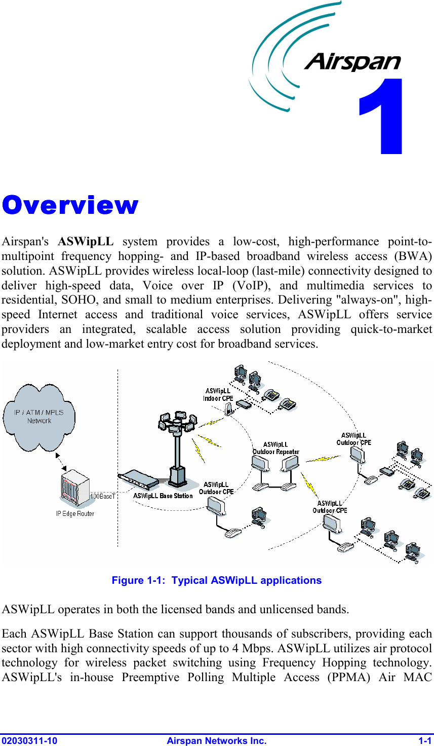
Airspan Networks
>
AIRSPAN BSR19 User Manual
Users Manual
Navigation menu
Upload a User Manual
Namespaces
Wiki Guide
HTML
PDF
Info
Views
User Manual
Discussion / Help
Navigation

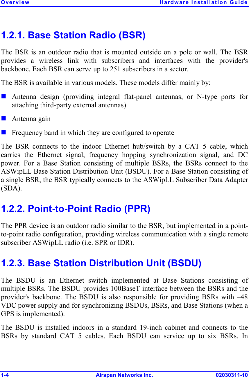
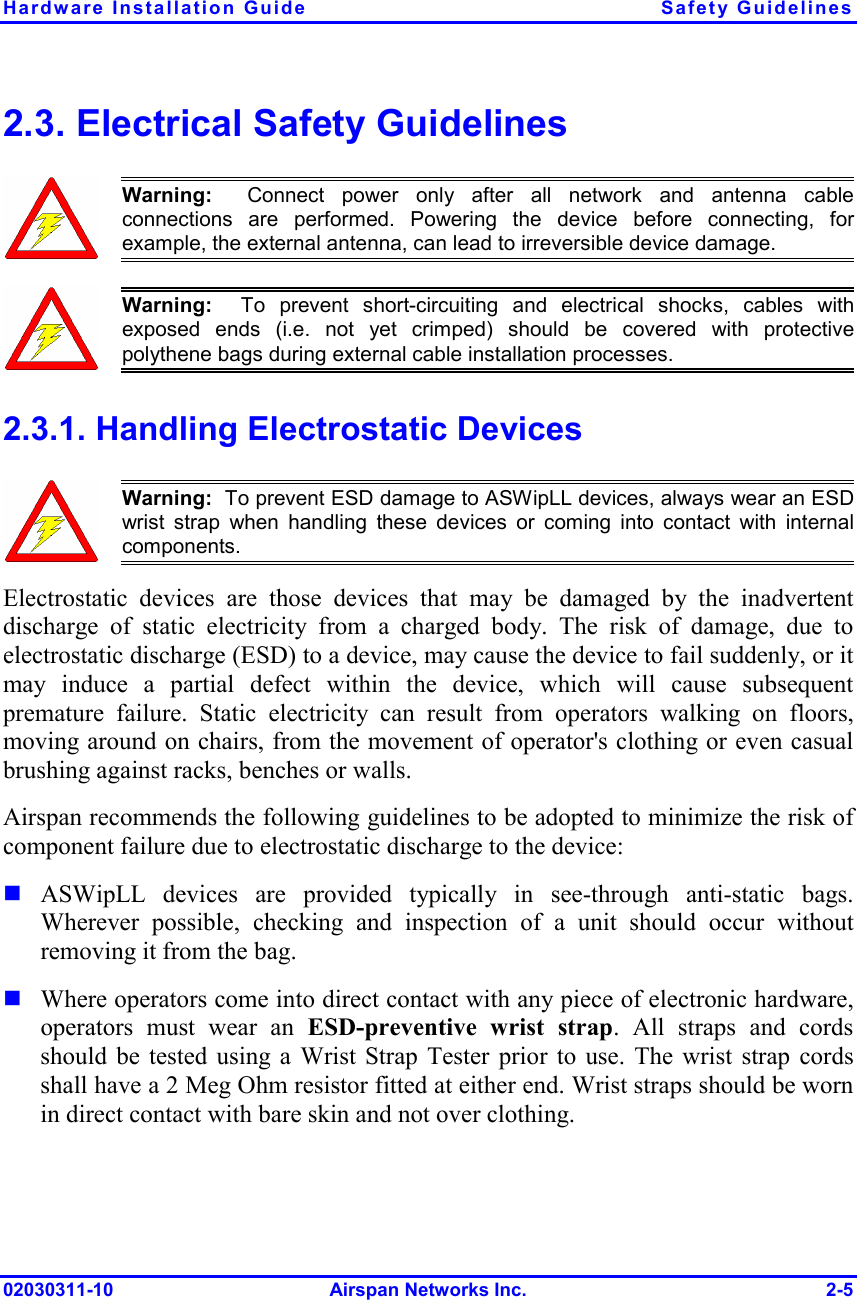
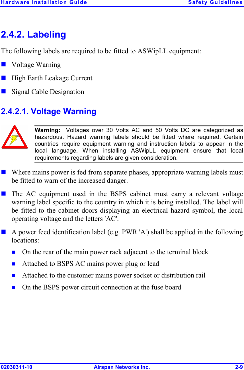
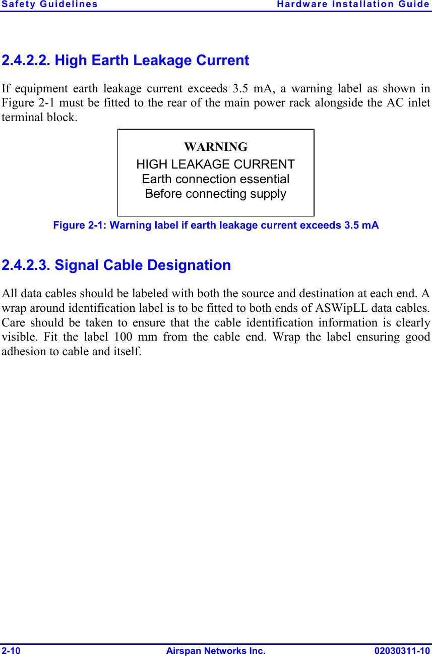
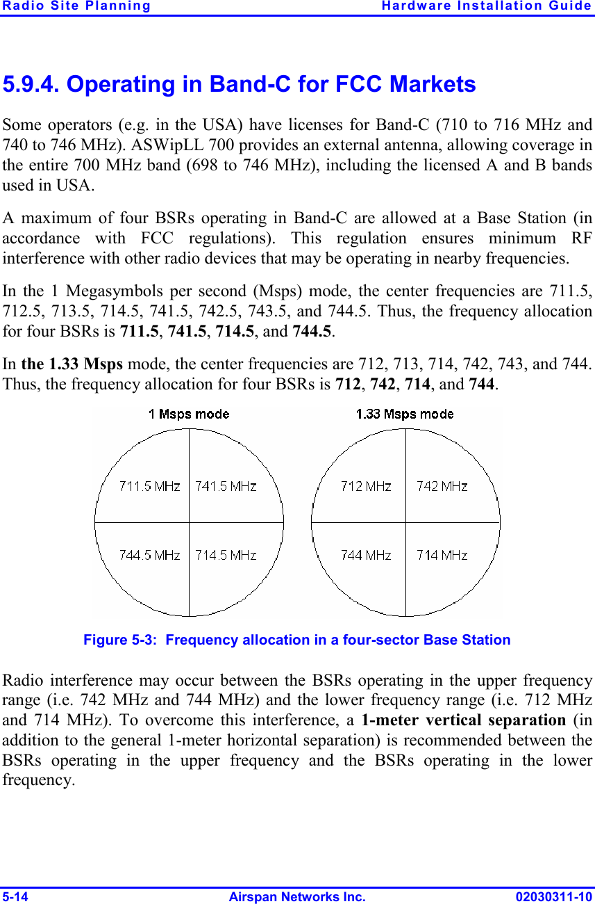
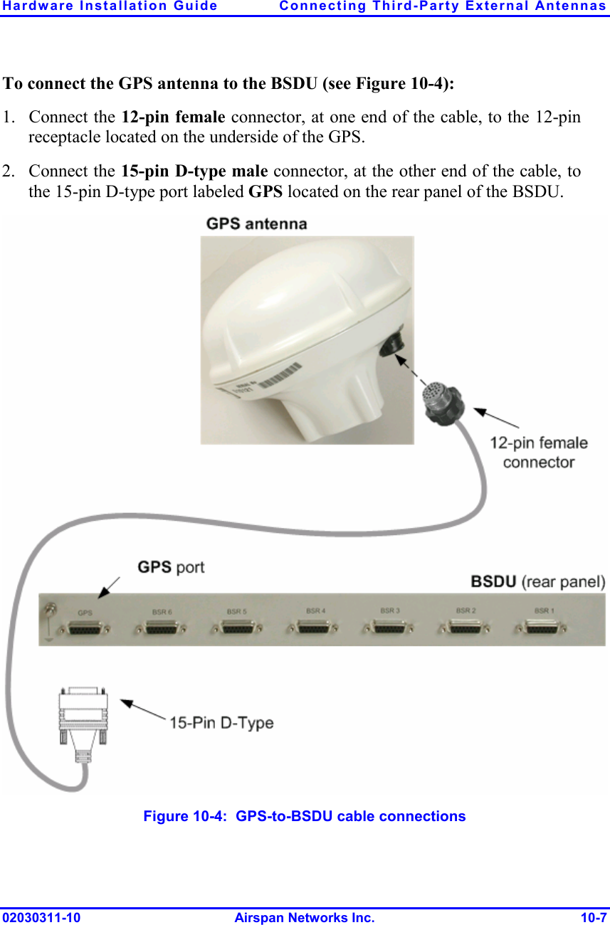
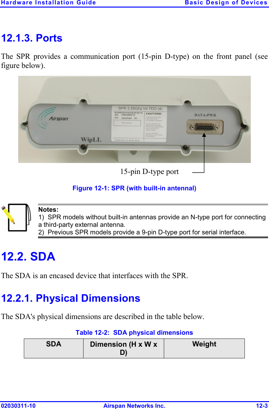
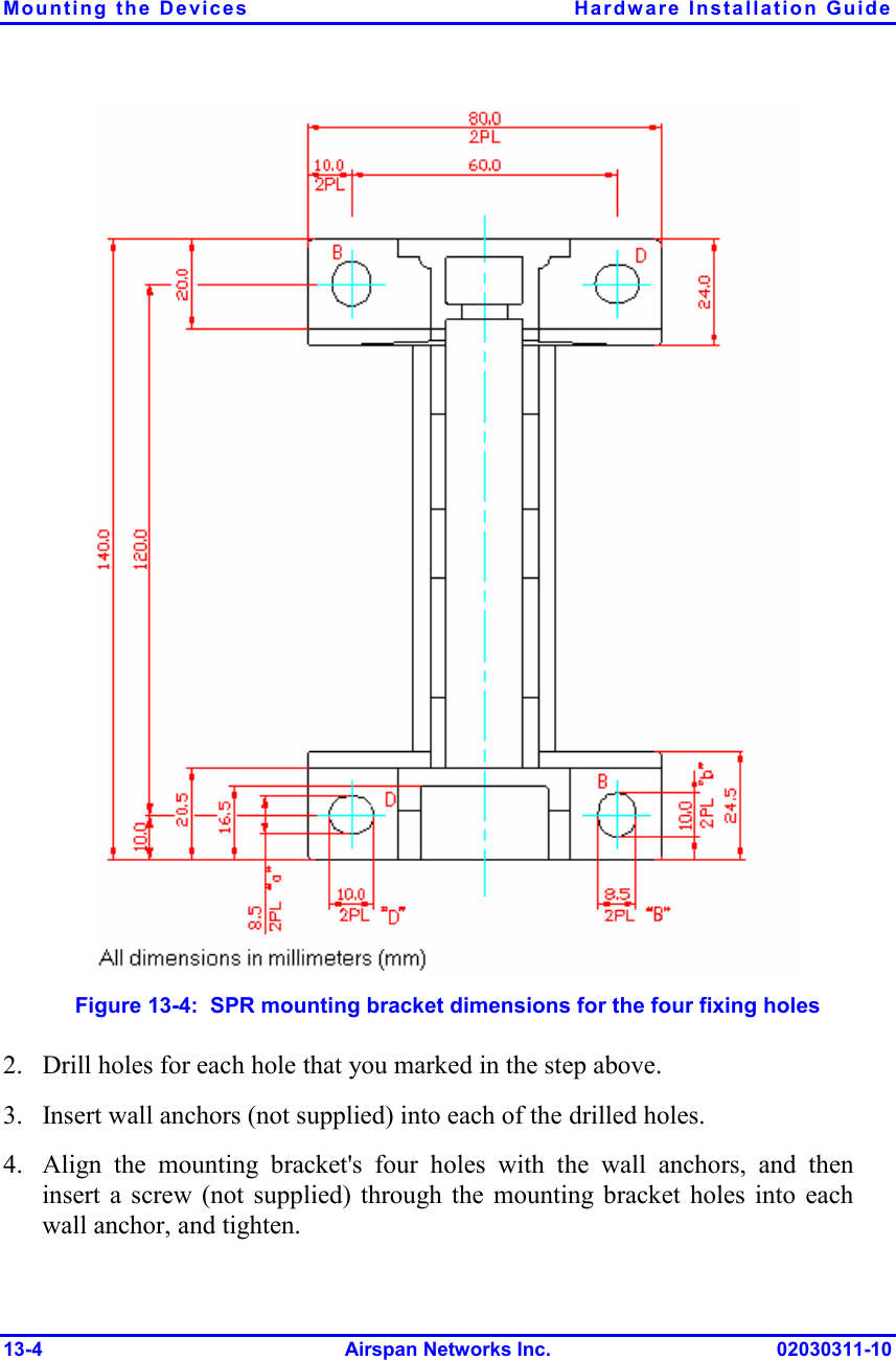
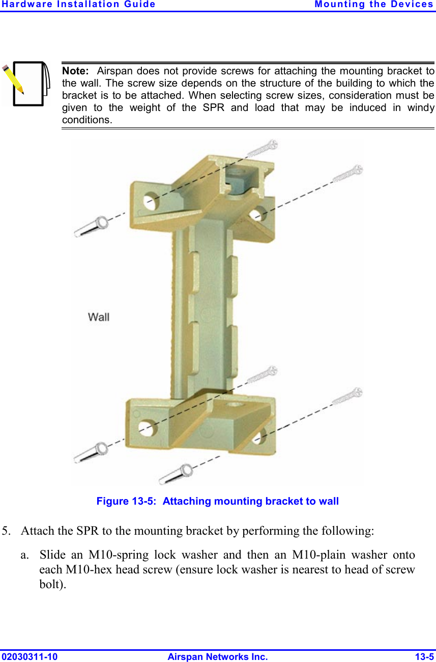
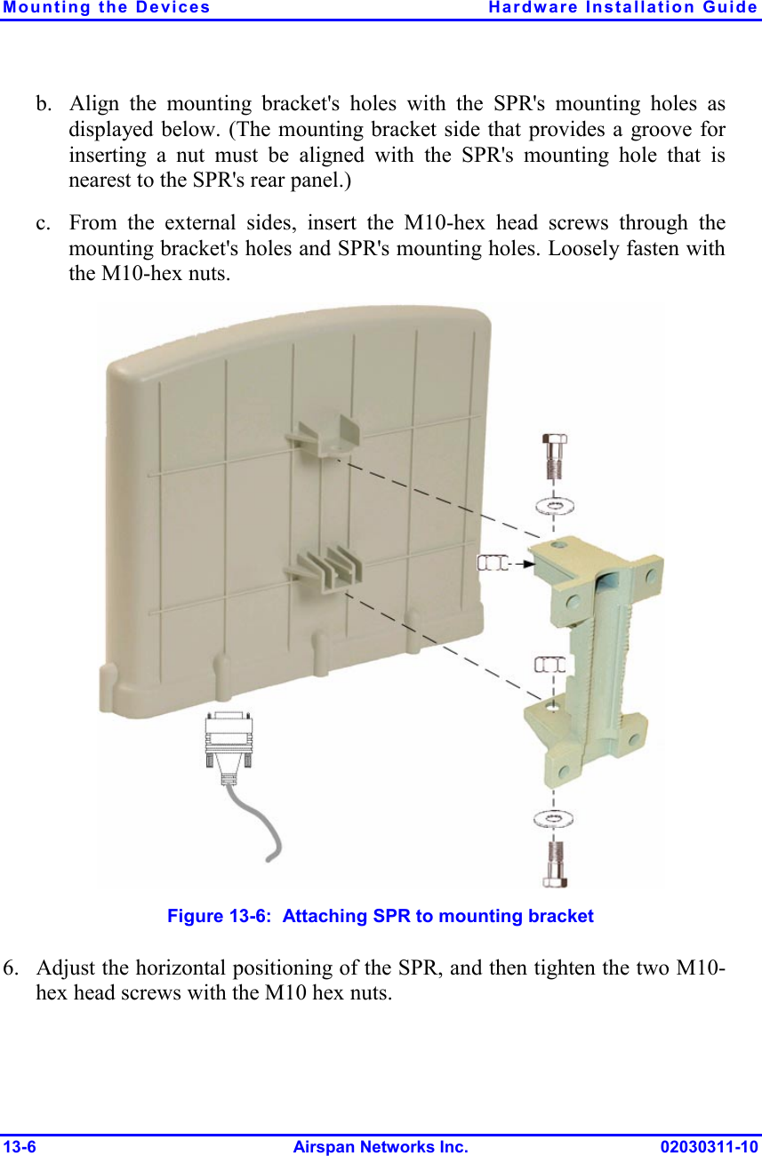
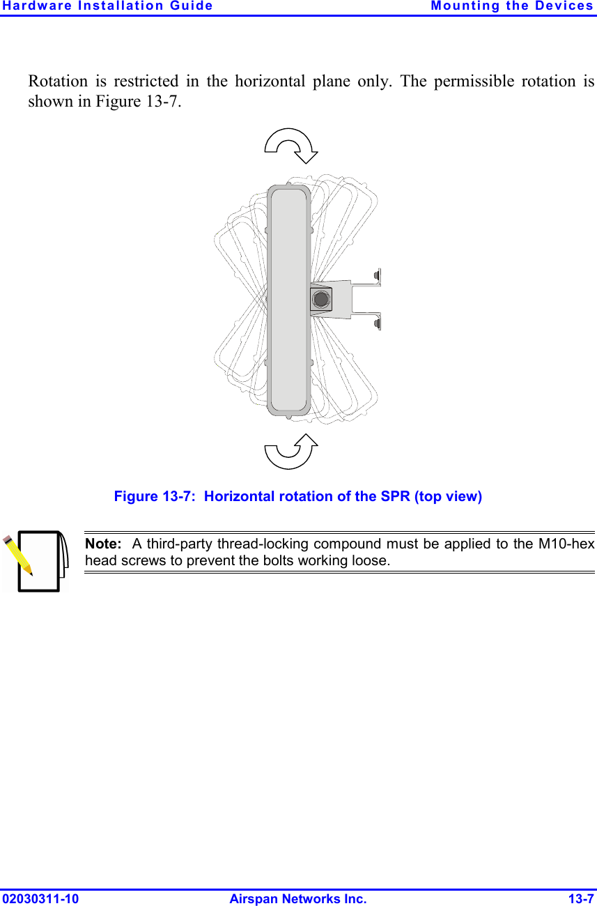
![Hardware Installation Guide Radio Site Planning 02030311-10 Airspan Networks Inc. 5-5 Prior to performing this test, you need to mount the radio/antenna in the desired installation spot. In general, you will be looking for frequencies with signal strengths of –85 dBm or greater. For using Airspan's spectrum analyzer tool, refer to the WipConfig User's Guide. For evaluating link quality using the Spectrum Analyzer, see Appendix G, "Evaluating Link Quality". 5.5. Adjacent Base Station Radios For installations involving co-location of BSRs, it is important to assign frequencies of maximum spacing. This is to reduce possible radio interference between adjacently installed BSRs. In addition, a 1-meter separation must exist between adjacent BSRs. 5.6. Calculating Link Budget Link budget is the computation of the maximal achievable reception level for the communication link between the Base Station and the subscriber site. This level is the minimum required received signal level (RSS) at the antenna port for the radio to close the communication link at a given data rate and under the worst-case fading channel. The weakest signal a receiver can successfully pick up and demodulate at an acceptable bit-error rate is called receiver sensitivity. This level must be greater or equal to the radio's receiver sensitivity, which is the minimum RF signal power level required at the input of a receiver for certain performance (e.g. > BER). This takes into account the following parameters: Transmit (dBm) EIRP: Tx transmitter power (dBm) - cable loss (dB) + Tx antenna gain (dBi) Propagation (dB): Fade Margin + Free space loss (dB) = [fade margin] + 32.44 + 20logd(km) + 20logf(MHz), where f is the frequency in MHz, and d is the distance between transmitting and receiving radios in km.](https://usermanual.wiki/Airspan-Networks/AIRSPAN-BSR19/User-Guide-593412-Page-49.png)