Airspan Networks AIRSPAN-WIPLL2 WippLL Radio User Manual Hardware Installation Guide

Airspan Networks Inc WippLL Radio Hardware Installation Guide

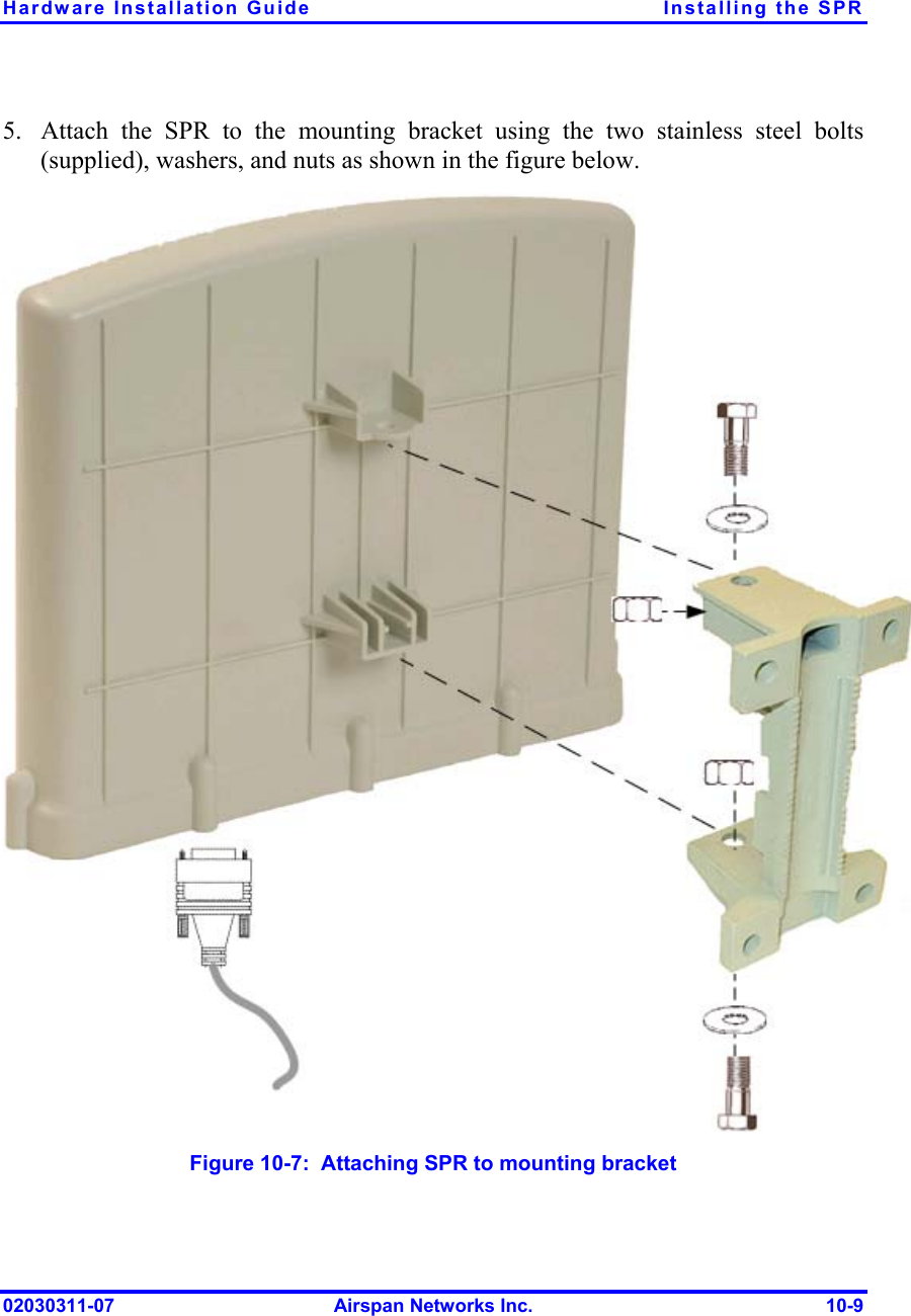
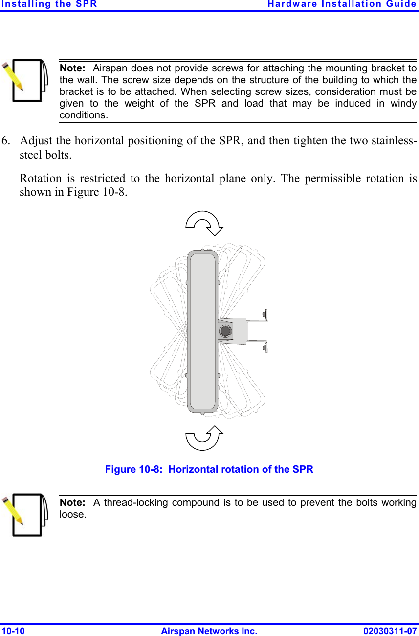
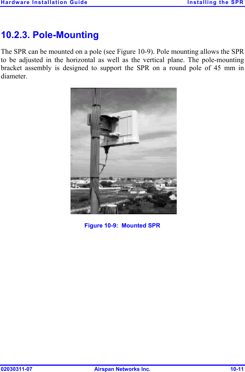
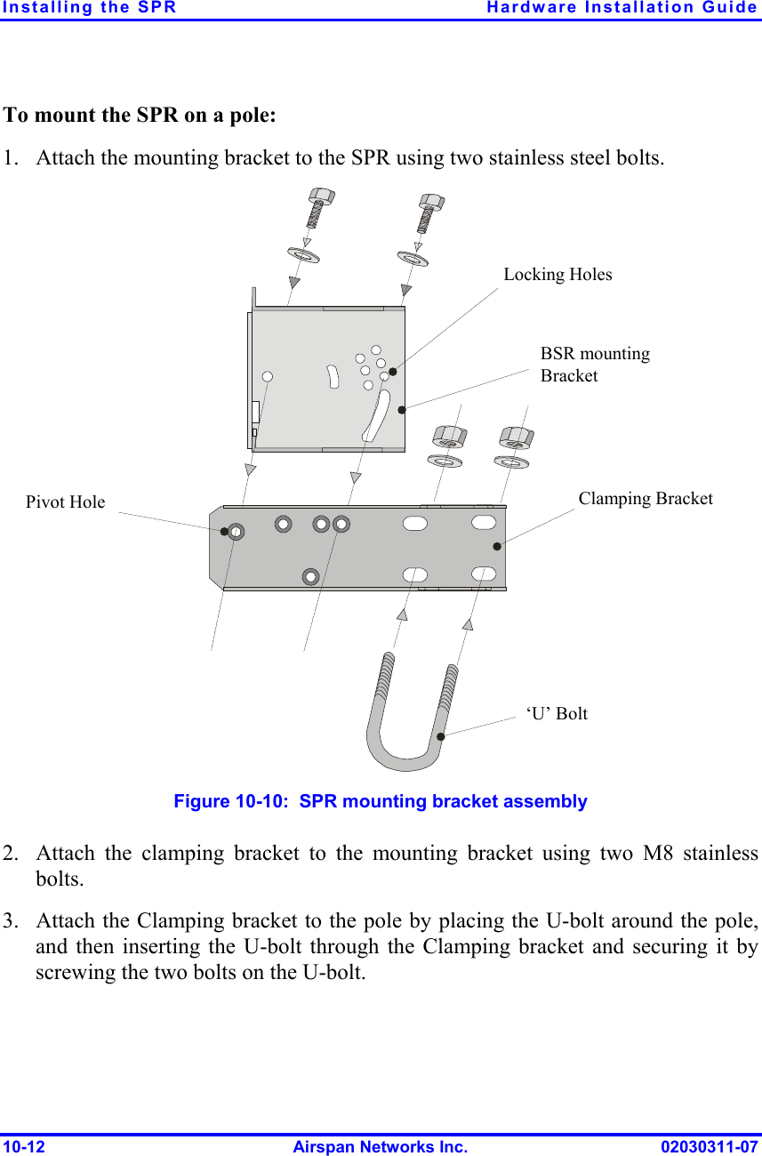
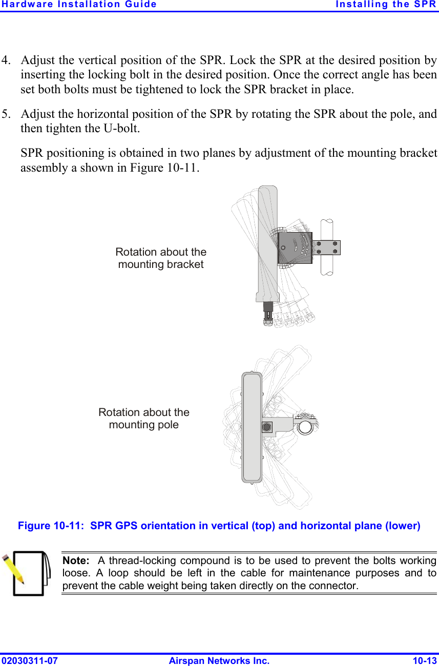
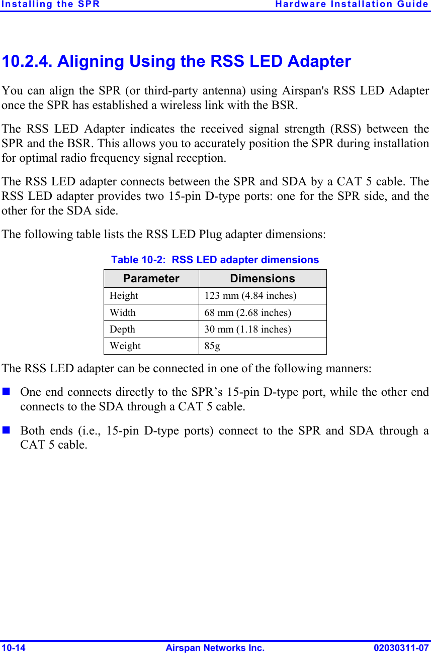
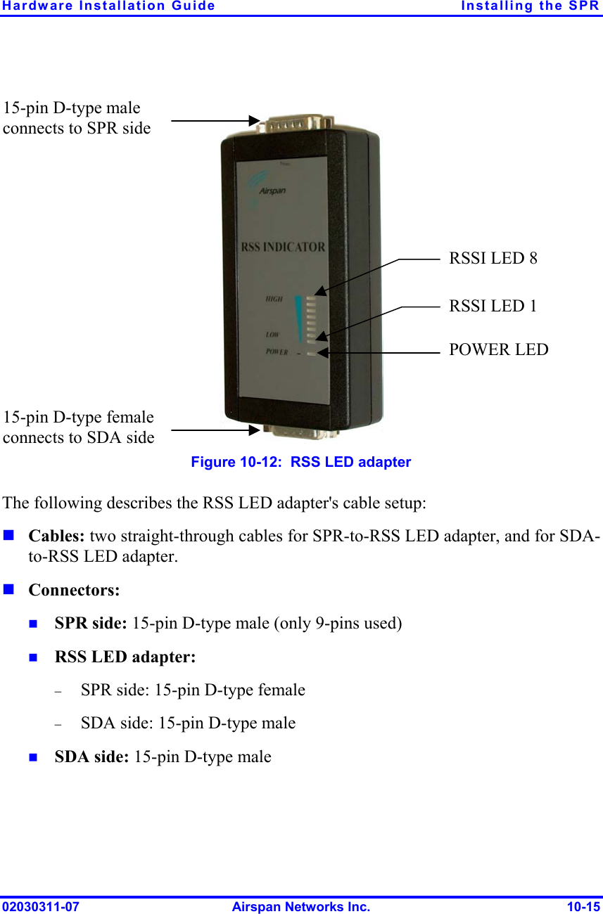
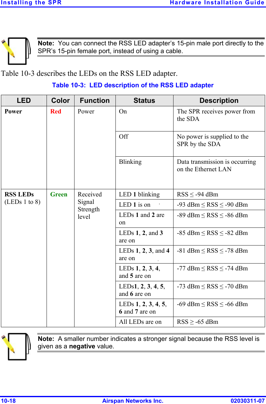
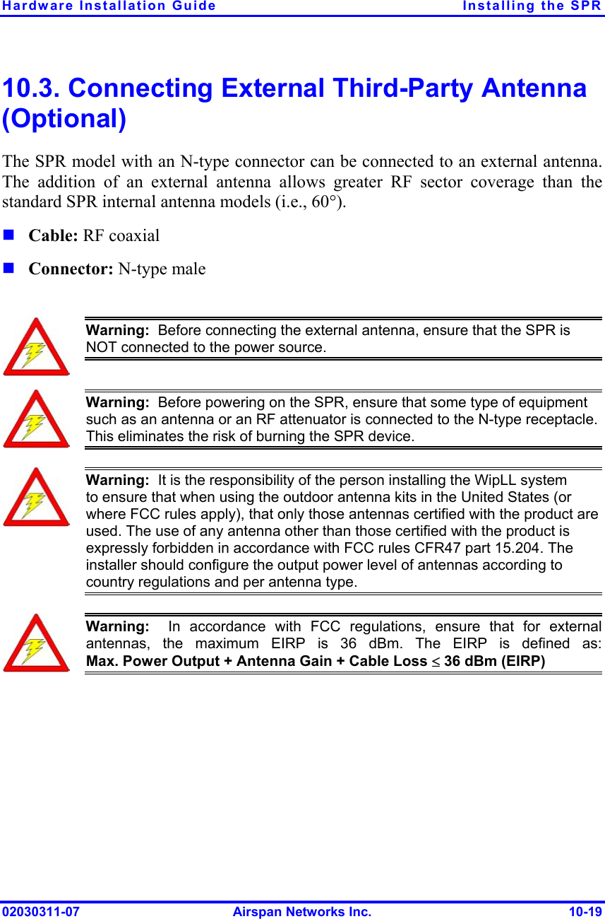
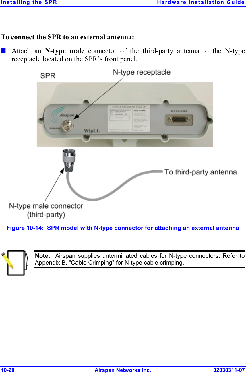
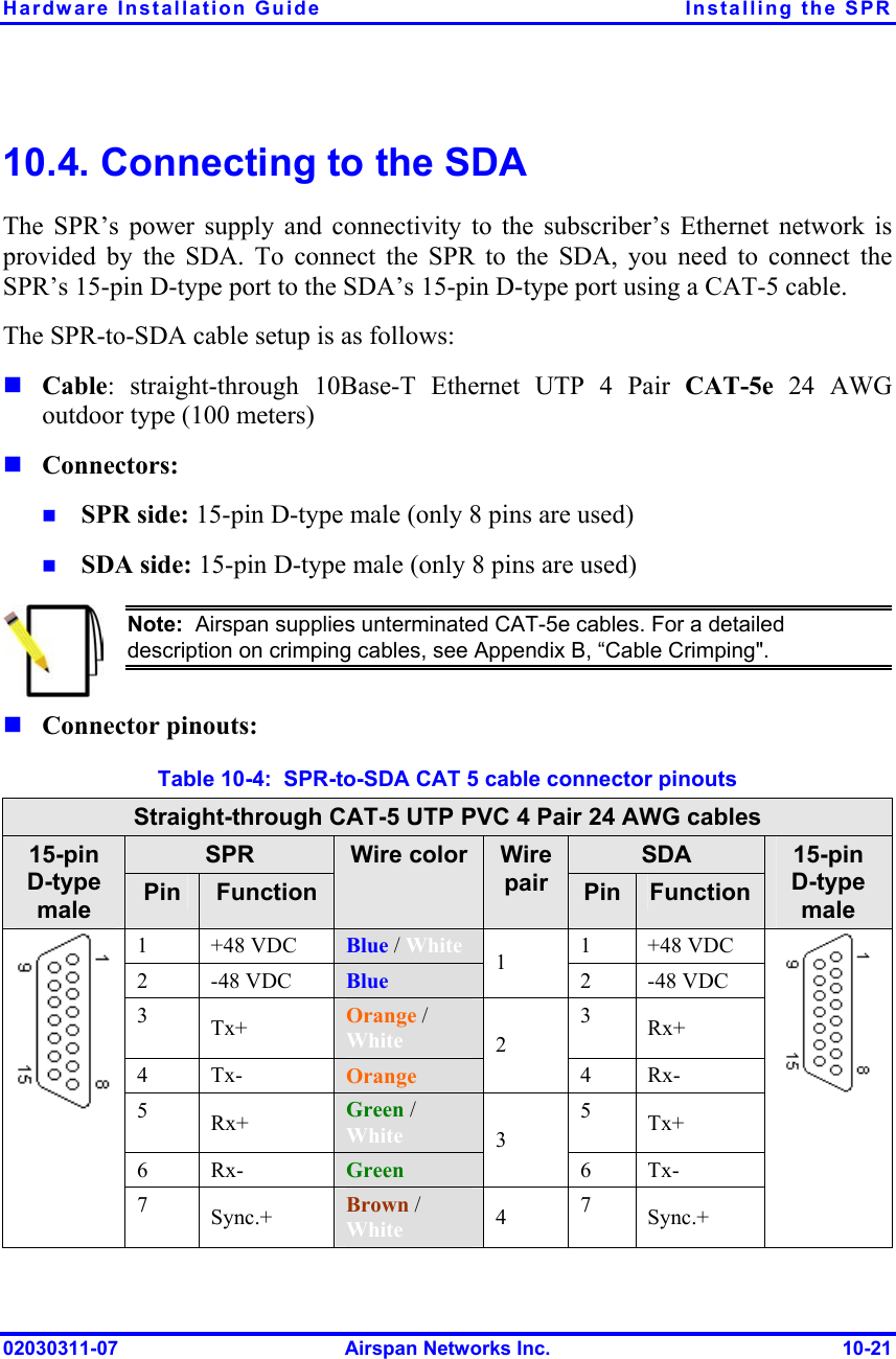
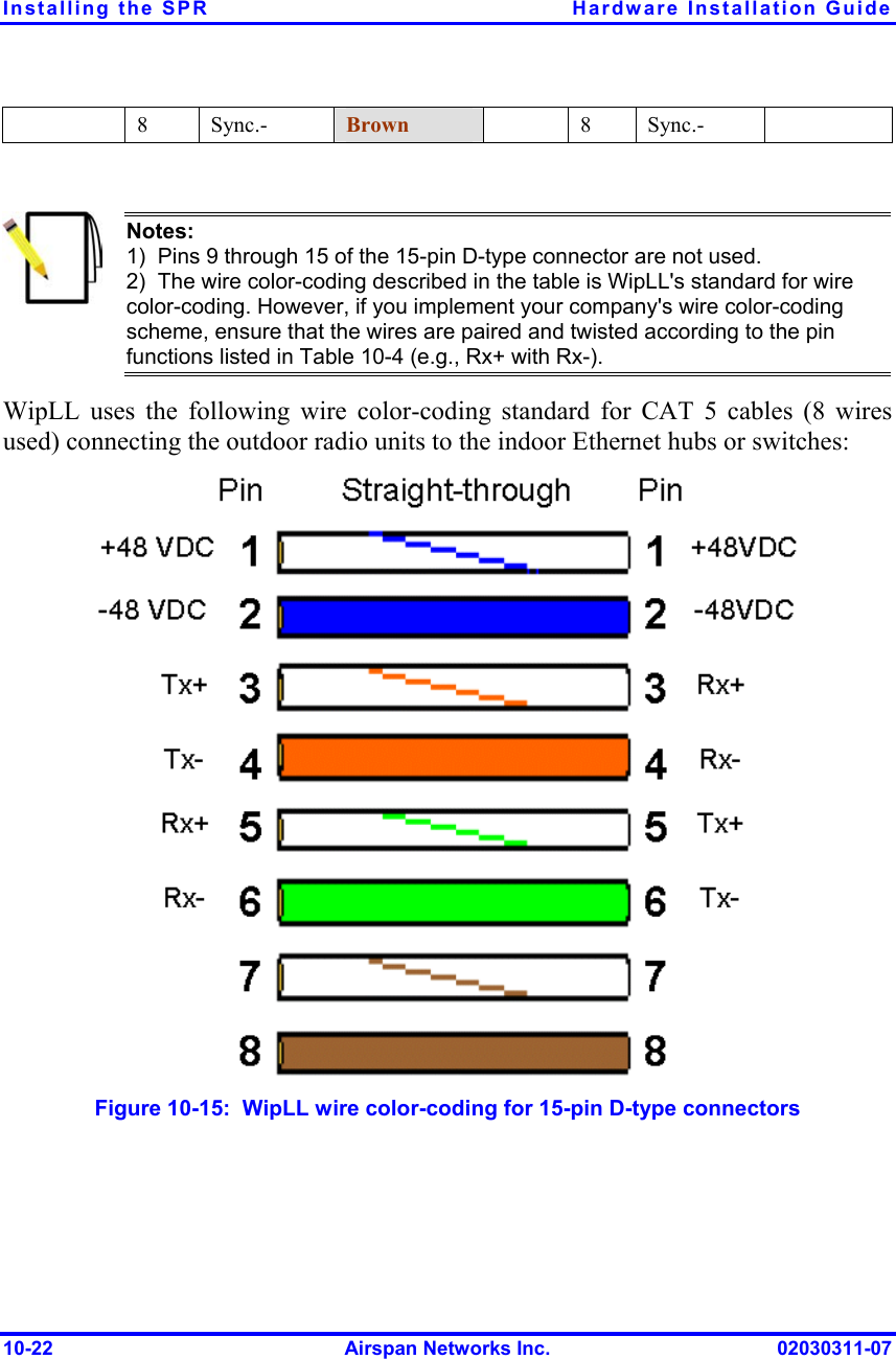
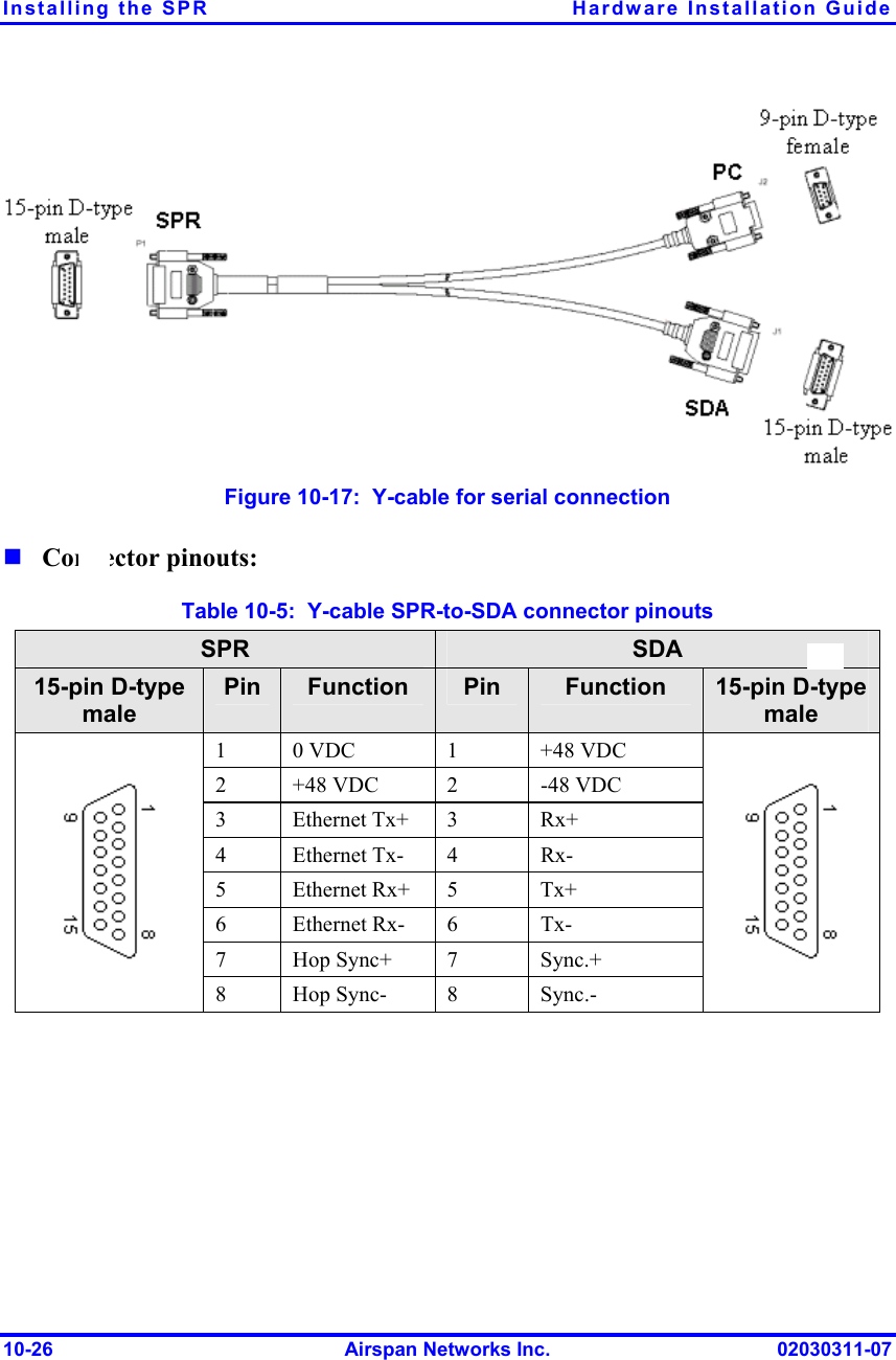
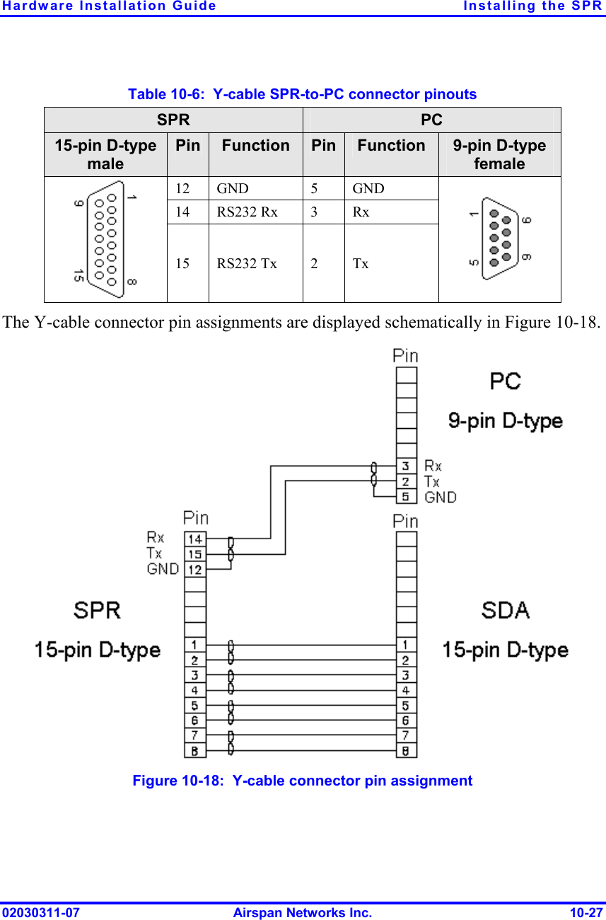
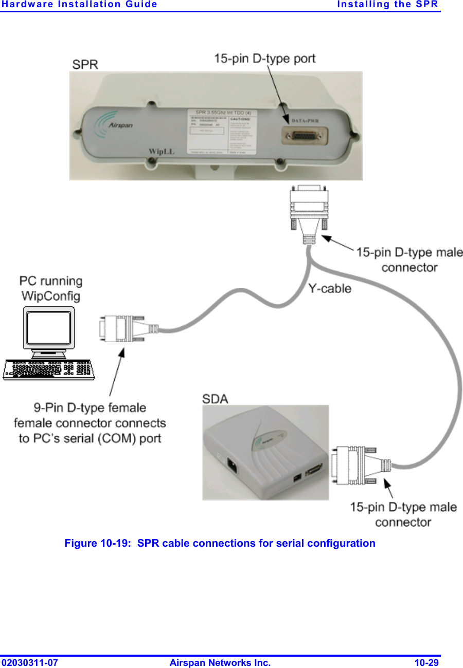
Installaton Manual Model 1

   Installing the SPR This chapter describes the installation of the WipLL Subscriber Premises Radio (SPR), located at the subscriber's premises.   Warning:  Cables with exposed ends (i.e., not yet crimped) should be coveredwith protective polythene bags during external cable installation processes.     Warning:  As the system emits microwave radiation, a minimum distance of500 mm must be maintained from the front of the SPR. However, for the 700MHz band (i.e. WipLL 700), when external antennas are used, a minimum distance of 800 mm must be maintained from the front of the device.    Warning:  To avoid electrical or fire hazard, connect the SPR to the powersupply only after mounting the SPR and connecting data cables.  Note:  Usually, the SPR is initialized (i.e., configured with an IP address) atAirspan's factory. However, if the SPR has not been configured, see Section 10.5, “Connecting to a PC for Serial Configuration”, before mounting the SPR. 1002030311-07  Airspan Networks Inc.  10-1
Installing the SPR  Hardware Installation Guide  Note:  The digital portion of the transceiver has been tested and found to comply with the limits for a Class B digital device, pursuant to part 15 of the FCC rules. These limits are designed to provide reasonable protection against harmful interference in a residential installation. This equipment generates, uses, and can radiate radio frequency energy and, if not installed and used in accordance with the instructions, may cause harmful interference to radio communications. However, there is no guarantee that interference will not occur in a particular installation. If this equipment does cause harmful interference to radio or television reception, which can be determined by turning the equipment on and off, the user is encouraged to try correct the interference by performing one or more of the following measures: -  Reorientate or relocate the receiving antenna -  Increase separation between the equipment and receiver -  Connect the equipment to an outlet on a circuit different from that to which the receiver is connected -  Consult the dealer or an experienced radio/TV technician for help  Note:  A minimum separation of 200 mm should exist between power and data cables.  10-2  Airspan Networks Inc.  02030311-07
Hardware Installation Guide  Installing the SPR 10.1. Physical Dimensions and Basic Design The SPR is encased in a chassis and provides access to the SPR’s communication port (15-pin D-type) at the front panel (see figure below). The SPR’s bottom panel provides holes for mounting the SPR to, for example, a pole or wall.   15-pin D-type port Figure  10-1: SPR (with built-in antennal) The SPR’s physical dimensions are described in the following table. Table  10-1:  SPR physical dimensions SPR model Parameter  Standard Gain Antenna High Gain Antenna  Comment Height  311 mm (12.24 inches)  400 mm (15.74 inches) Width  224 mm (8.82 inches)  317 mm (12.48 inches) Depth  65.5 mm (2.58 inches)  65.5 mm (2.58 inches) Weight  2.5 kg  4.7 kg The SPR’s physical dimensions exclude the mounting kit. SPR models with an N-type receptacle for attaching a third-party external antenna are also available.  02030311-07  Airspan Networks Inc.  10-3
Installing the SPR  Hardware Installation Guide 10.2. Mounting the SPR The SPR can be mounted on a wall or pole. The SPR is mounted using the mounting holes located on the SPR’s bottom panel (see Figure  10-2), and the mounting bracket (provided). The mounting brackets for wall- and pole mounting are different from one another.  Mounting holesFigure  10-2:  SPR bottom panel providing holes for mounting 10-4  Airspan Networks Inc.  02030311-07
Hardware Installation Guide  Installing the SPR 10.2.1. Minimum Distance between SPRs  A minimum of 3-meter separation is required between mounted SPRs and existing customer radio equipment when not transmitting on the same sector (see Figure  10-3).  3.0 metres Figure  10-3:  SPR separation when not transmitting on the same sector A 1-meter separation is required between SPRs when on the same sector and transmitting to the same BSR without requiring shielding (see Figure  10-4).  1.0 metre Figure  10-4:  SPR separation when transmitting on the same sector to the same BSR 02030311-07  Airspan Networks Inc.  10-5
Installing the SPR  Hardware Installation Guide 10.2.2. Wall-Mounting SPR wall mounting is performed in two stages:   1. 2. 3. 4. Attaching the mounting bracket to the SPR’s mounting holes. Attaching the mounting bracket (attached to the SPR) to the wall. To mount the SPR on a wall: Position the mounting bracket on the mounting surface (e.g., wall), and then use a pencil to mark the position of the four mounting holes. Drill holes for each hole that you marked in the step above. Insert wall anchors into each of the drilled holes. Align the mounting bracket’s four holes with the wall anchors, and then insert a screw through the mounting bracket holes into each wall anchor, and tighten. The figure below displays relevant dimensions of the mounting bracket. Note the two different sized fixing holes.  10-6  Airspan Networks Inc.  02030311-07
Hardware Installation Guide  Installing the SPR  Figure  10-5:  Attaching mounting bracket to wall Below is a diagram illustrating the fixing dimensions of the mounting bracket. Ensure that the distance between the hole centers are 120 mm and 60 mm.  02030311-07  Airspan Networks Inc.  10-7
Installing the SPR  Hardware Installation Guide  Figure  10-6:  SPR mounting bracket dimensions for the four fixing holes 10-8  Airspan Networks Inc.  02030311-07
Hardware Installation Guide  Installing the SPR 5.  Attach the SPR to the mounting bracket using the two stainless steel bolts (supplied), washers, and nuts as shown in the figure below.  Figure  10-7:  Attaching SPR to mounting bracket 02030311-07  Airspan Networks Inc.  10-9
Installing the SPR  Hardware Installation Guide  Note:  Airspan does not provide screws for attaching the mounting bracket to the wall. The screw size depends on the structure of the building to which thebracket is to be attached. When selecting screw sizes, consideration must begiven to the weight of the SPR and load that may be induced in windy conditions. 6.  Adjust the horizontal positioning of the SPR, and then tighten the two stainless-steel bolts. Rotation is restricted to the horizontal plane only. The permissible rotation is shown in Figure  10-8.   Figure  10-8:  Horizontal rotation of the SPR  Note:  A thread-locking compound is to be used to prevent the bolts workingloose.  10-10  Airspan Networks Inc.  02030311-07
Hardware Installation Guide  Installing the SPR 10.2.3. Pole-Mounting The SPR can be mounted on a pole (see Figure  10-9). Pole mounting allows the SPR to be adjusted in the horizontal as well as the vertical plane. The pole-mounting bracket assembly is designed to support the SPR on a round pole of 45 mm in diameter.  Figure  10-9:  Mounted SPR 02030311-07  Airspan Networks Inc.  10-11
Installing the SPR  Hardware Installation Guide To mount the SPR on a pole: 1.  Attach the mounting bracket to the SPR using two stainless steel bolts. Pivot Hole ‘U’ Bolt  Locking Holes BSR mounting Bracket  Clamping Bracket   Figure  10-10:  SPR mounting bracket assembly 2. 3. Attach the clamping bracket to the mounting bracket using two M8 stainless bolts.  Attach the Clamping bracket to the pole by placing the U-bolt around the pole, and then inserting the U-bolt through the Clamping bracket and securing it by screwing the two bolts on the U-bolt.   10-12  Airspan Networks Inc.  02030311-07
Hardware Installation Guide  Installing the SPR 4. 5. Adjust the vertical position of the SPR. Lock the SPR at the desired position by inserting the locking bolt in the desired position. Once the correct angle has been set both bolts must be tightened to lock the SPR bracket in place. Adjust the horizontal position of the SPR by rotating the SPR about the pole, and then tighten the U-bolt. SPR positioning is obtained in two planes by adjustment of the mounting bracket assembly a shown in Figure  10-11.  Rotation about the mounting poleRotation about the mounting bracket Figure  10-11:  SPR GPS orientation in vertical (top) and horizontal plane (lower)  Note:  A thread-locking compound is to be used to prevent the bolts workingloose. A loop should be left in the cable for maintenance purposes and to prevent the cable weight being taken directly on the connector. 02030311-07  Airspan Networks Inc.  10-13
Installing the SPR  Hardware Installation Guide 10.2.4. Aligning Using the RSS LED Adapter You can align the SPR (or third-party antenna) using Airspan's RSS LED Adapter once the SPR has established a wireless link with the BSR. The RSS LED Adapter indicates the received signal strength (RSS) between the SPR and the BSR. This allows you to accurately position the SPR during installation for optimal radio frequency signal reception.  The RSS LED adapter connects between the SPR and SDA by a CAT 5 cable. The RSS LED adapter provides two 15-pin D-type ports: one for the SPR side, and the other for the SDA side.  The following table lists the RSS LED Plug adapter dimensions: Table  10-2:  RSS LED adapter dimensions Parameter  Dimensions Height  123 mm (4.84 inches) Width  68 mm (2.68 inches) Depth  30 mm (1.18 inches) Weight 85g The RSS LED adapter can be connected in one of the following manners:   One end connects directly to the SPR’s 15-pin D-type port, while the other end connects to the SDA through a CAT 5 cable. Both ends (i.e., 15-pin D-type ports) connect to the SPR and SDA through a CAT 5 cable. 10-14  Airspan Networks Inc.  02030311-07
Hardware Installation Guide  Installing the SPR  15-pin D-type male connects to SPR side  RSSI LED 8 RSSI LED 1 POWER LED 15-pin D-type female connects to SDA side Figure  10-12:  RSS LED adapter The following describes the RSS LED adapter's cable setup:      Cables: two straight-through cables for SPR-to-RSS LED adapter, and for SDA-to-RSS LED adapter. Connectors: SPR side: 15-pin D-type male (only 9-pins used) RSS LED adapter:  −  SPR side: 15-pin D-type female  −  SDA side: 15-pin D-type male SDA side: 15-pin D-type male 02030311-07  Airspan Networks Inc.  10-15
Installing the SPR  Hardware Installation Guide To connect the RSSI LED adapter (see Figure  10-13): 1. 2. 3. 4. Connect the 15-pin D-type male connector, at one end of the straight-through cable, to the SPR. Connect the 15-pin D-type female connector, at the other end of the straight-through cable from the SPR, to the RSS LED adapter. Connect the 15-pin D-type male connector, at one end of the straight-through cable, to the SDA. Connect the 15-pin D-type male connector, at the other end of the straight-through cable from the SDA, to the RSS LED adapter. 10-16  Airspan Networks Inc.  02030311-07
Hardware Installation Guide  Installing the SPR  Figure  10-13: Connecting the RSS LED Plug adapter 02030311-07  Airspan Networks Inc.  10-17
Installing the SPR  Hardware Installation Guide  Note:  You can connect the RSS LED adapter’s 15-pin male port directly to the SPR’s 15-pin female port, instead of using a cable.  Table  10-3 describes the LEDs on the RSS LED adapter. Table  10-3:  LED description of the RSS LED adapter LED  Color  Function  Status  Description On  The SPR receives power from the SDA  Off  No power is supplied to the SPR by the SDA Power  Red  Power Blinking  Data transmission is occurring on the Ethernet LAN LED 1 blinking  RSS ≤ -94 dBm  LED 1 is on  -93 dBm ≤ RSS ≤ -90 dBm LEDs 1 and 2 are on -89 dBm ≤ RSS ≤ -86 dBm LEDs 1, 2, and 3 are on -85 dBm ≤ RSS ≤ -82 dBm LEDs 1, 2, 3, and 4 are on -81 dBm ≤ RSS ≤ -78 dBm LEDs 1, 2, 3, 4, and 5 are on -77 dBm ≤ RSS ≤ -74 dBm LEDs1, 2, 3, 4, 5, and 6 are on -73 dBm ≤ RSS ≤ -70 dBm LEDs 1, 2, 3, 4, 5, 6 and 7 are on -69 dBm ≤ RSS ≤ -66 dBm RSS LEDs  (LEDs 1 to 8) Green  Received Signal Strength level All LEDs are on  RSS ≥ -65 dBm  Note:  A smaller number indicates a stronger signal because the RSS level is given as a negative value.  10-18  Airspan Networks Inc.  02030311-07
Hardware Installation Guide  Installing the SPR 10.3. Connecting External Third-Party Antenna (Optional) The SPR model with an N-type connector can be connected to an external antenna. The addition of an external antenna allows greater RF sector coverage than the standard SPR internal antenna models (i.e., 60°).   Cable: RF coaxial  Connector: N-type male   Warning:  Before connecting the external antenna, ensure that the SPR is NOT connected to the power source.   Warning:  Before powering on the SPR, ensure that some type of equipment such as an antenna or an RF attenuator is connected to the N-type receptacle. This eliminates the risk of burning the SPR device.  Warning:  It is the responsibility of the person installing the WipLL system to ensure that when using the outdoor antenna kits in the United States (or where FCC rules apply), that only those antennas certified with the product are used. The use of any antenna other than those certified with the product is expressly forbidden in accordance with FCC rules CFR47 part 15.204. The installer should configure the output power level of antennas according to country regulations and per antenna type.  Warning:  In accordance with FCC regulations, ensure that for externalantennas, the maximum EIRP is 36 dBm. The EIRP is defined as:Max. Power Output + Antenna Gain + Cable Loss ≤ 36 dBm (EIRP)  02030311-07  Airspan Networks Inc.  10-19
Installing the SPR  Hardware Installation Guide To connect the SPR to an external antenna:  Attach an N-type male connector of the third-party antenna to the N-type receptacle located on the SPR’s front panel.  Figure  10-14:  SPR model with N-type connector for attaching an external antenna   Note:  Airspan supplies unterminated cables for N-type connectors. Refer to Appendix B, “Cable Crimping" for N-type cable crimping. 10-20  Airspan Networks Inc.  02030311-07
Hardware Installation Guide  Installing the SPR 10.4. Connecting to the SDA The SPR’s power supply and connectivity to the subscriber’s Ethernet network is provided by the SDA. To connect the SPR to the SDA, you need to connect the SPR’s 15-pin D-type port to the SDA’s 15-pin D-type port using a CAT-5 cable. The SPR-to-SDA cable setup is as follows:     Cable: straight-through 10Base-T Ethernet UTP 4 Pair CAT-5e 24 AWG outdoor type (100 meters) Connectors:  SPR side: 15-pin D-type male (only 8 pins are used) SDA side: 15-pin D-type male (only 8 pins are used)  Note:  Airspan supplies unterminated CAT-5e cables. For a detailed description on crimping cables, see Appendix B, “Cable Crimping".  Connector pinouts: Table  10-4:  SPR-to-SDA CAT 5 cable connector pinouts Straight-through CAT-5 UTP PVC 4 Pair 24 AWG cables SPR  SDA 15-pin D-type male  Pin  Function Wire color  Wire pair  Pin  Function 15-pin  D-type male 1 +48 VDC Blue / White 1 +48 VDC 2 -48 VDC Blue 1  2 -48 VDC 3  Tx+  Orange / White 3  Rx+ 4 Tx-  Orange 2 4 Rx- 5  Rx+  Green / White 5  Tx+ 6 Rx-  Green 3 6 Tx-  7  Sync.+  Brown / White 4  7  Sync.+  02030311-07  Airspan Networks Inc.  10-21
Installing the SPR  Hardware Installation Guide 8 Sync.- Brown   8 Sync.-       Notes:   1)  Pins 9 through 15 of the 15-pin D-type connector are not used. 2)  The wire color-coding described in the table is WipLL's standard for wire color-coding. However, if you implement your company's wire color-coding scheme, ensure that the wires are paired and twisted according to the pin functions listed in Table  10-4 (e.g., Rx+ with Rx-).  WipLL uses the following wire color-coding standard for CAT 5 cables (8 wires used) connecting the outdoor radio units to the indoor Ethernet hubs or switches:  Figure  10-15:  WipLL wire color-coding for 15-pin D-type connectors  10-22  Airspan Networks Inc.  02030311-07
Hardware Installation Guide  Installing the SPR  Warning:  To avoid electrical shock, before connecting the SPR to the SDA,ensure that the SDA is not connected to the power supply.  Notes:   1)  The wires are twisted together in pairs, for example, blue/white with blue, and orange/white with orange. This prevents electrical interference between the transmitter pins. For example, pin 3 (Tx+; orange / white) is paired and twisted with pin 4 (Tx-; orange). 2)  The SDA connector pinouts are the same for all SDA models (SDA-1, SDA-4H, SDA-4S, SDA-4S/VL, SDA-4S/Vltag, SDA-4S/1H3L, and SDA-4S/VL/1H3L). To connect the SPR to the SDA  (see Figure  10-16): 1. 2. Connect the 15-pin D-type connector, at one end of the CAT 5 cable, to the SPR’s 15-pin D-type port labeled DATA POWER SYNC. Connect the 15-pin D-type connector, at the other end of the CAT 5 cable, to the SDA’s 15-pin D-type port. 02030311-07  Airspan Networks Inc.  10-23
Installing the SPR  Hardware Installation Guide  Figure  10-16:  SPR-to-SDA cable connections  Note:  The maximum cable length permissible between the SPR and SDA is 100 meters. 10-24  Airspan Networks Inc.  02030311-07
Hardware Installation Guide  Installing the SPR 10.5. Connecting to a PC for Serial Configuration To configure an SPR, you need to connect a PC running the WipLL WipConfig configuration tool to the SPR. The SPR’s 15-pin D-type port also provides serial interface to a PC for SPR initial configuration. This port uses 9 of its 15 pins for serial interface; the remaining pins are used for interfacing with the SDA with which the SPR remains connected. To connect the SPR to the management station (i.e., PC) and the SDA, a Y-cable (splitter) is used.  Note:  SPR configuration is performed while the SPR is connected to the SDA.The SPR-to-PC and SDA cable connections for SPR serial configuration are as follows:      Connectors: SPR side: 15-pin D-type male (only 9-pins used) PC side: 9-pin D-type (RS-232) SDA side: 15-pin D-type male Cable: straight-through Y-cable 02030311-07  Airspan Networks Inc.  10-25
Installing the SPR  Hardware Installation Guide   Figure  10-17:  Y-cable for serial connection  Connector pinouts:   Table  10-5:  Y-cable SPR-to-SDA connector pinouts SPR  SDA 15-pin D-type male Pin  Function  Pin  Function  15-pin D-type male 1  0 VDC  1  +48 VDC 2  +48 VDC  2  -48 VDC 3 Ethernet Tx+ 3  Rx+ 4 Ethernet Tx- 4  Rx- 5 Ethernet Rx+ 5  Tx+ 6 Ethernet Rx- 6  Tx- 7 Hop Sync+ 7  Sync.+  8 Hop Sync- 8  Sync.-    10-26  Airspan Networks Inc.  02030311-07
Hardware Installation Guide  Installing the SPR Table  10-6:  Y-cable SPR-to-PC connector pinouts SPR  PC 15-pin D-type male Pin  Function  Pin Function  9-pin D-type female 12 GND  5  GND 14 RS232 Rx  3  Rx  15 RS232 Tx  2  Tx  The Y-cable connector pin assignments are displayed schematically in Figure  10-18.  Figure  10-18:  Y-cable connector pin assignment 02030311-07  Airspan Networks Inc.  10-27
Installing the SPR  Hardware Installation Guide To connect the SPR to a PC for serial configuration (see Figure  10-19): 1. 2. 3. Connect the 15-pin D-type male connector, at the one end of the Y-cable, to the SPR. Connect the 15-pin D-type male connector, at the other end of the Y-cable, to the SDA. Connect the 9-pin D-type female (RS232) connector, at the other end of the Y-cable, to the PC’s serial port. 10-28  Airspan Networks Inc.  02030311-07
Hardware Installation Guide  Installing the SPR  Figure  10-19:  SPR cable connections for serial configuration 02030311-07  Airspan Networks Inc.  10-29
Installing the SPR  Hardware Installation Guide  Note: For performing SPR initial configuration using WipLL’s management applications, refer to Airspan’s WipConfig User’s Guide or WipConfig PDA User’s Guide. 10.6. Connecting Power The SPR receives power through its 15-pin D-type port from the SDA. In turn, the SDA connects to an external AC-DC power adapter from where it receives power. The SDA provides 48 VDC nominal power to the SPR (minimum of 30 VDC: maximum of 55 VDC).  Warning:  If you are using an external antenna, ensure that you connect theantenna before connecting the SPR to the power source.    Note:  For a description on connecting power to the SPR and SDA, see Chapter 9, “Installing the SDA”.  10-30  Airspan Networks Inc.  02030311-07

Navigation menu