Airspan Networks AIRSPAN-WIPLL9 WippLL Radio User Manual Inst 02

Airspan Networks Inc WippLL Radio Inst 02

Contents

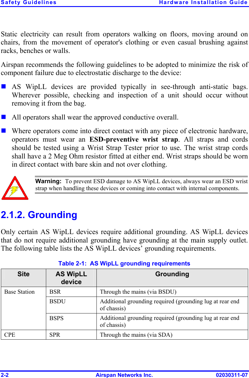
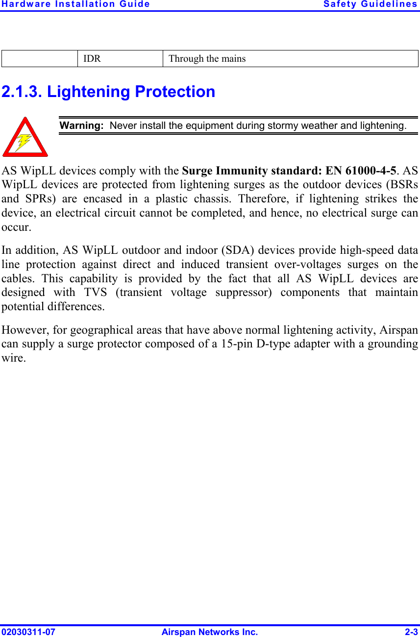
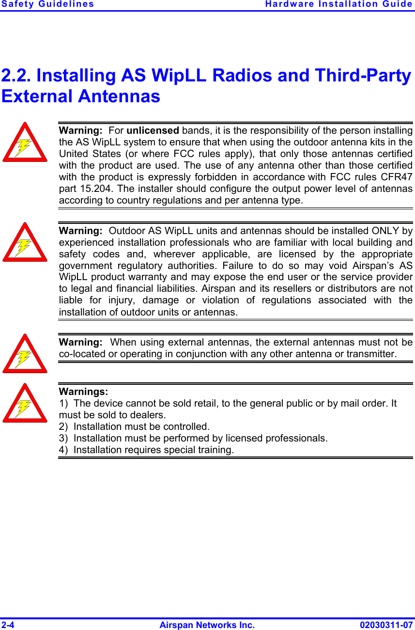
Safety Installation Information

 02030311-07  Airspan Networks Inc.  2-1   Safety Guidelines This chapter outlines safety guidelines when installing the AS WipLL system.  Warning:  The user and the installer should be aware that changes andmodifications not expressly approved by Airspan Networks could void theuser’s authority to operate the equipment.  Warning:  Never install equipment that is damaged.  Warning:  Only qualified personnel should be allowed to install, replace, andservice the AS WipLL equipment. 2.1. Electrical Safety Guidelines  Warning:  Disconnect all power when installing. 2.1.1. Handling Electrostatic Devices Electrostatic devices are those devices that may be damaged by the inadvertent discharge of static electricity from a charged body. The risk of damage, due to electrostatic discharge (ESD) to a device, may cause the device to fail suddenly, or it may induce a partial defect within the device, which will cause subsequent premature failure. 2
Safety Guidelines  Hardware Installation Guide 2-2  Airspan Networks Inc.  02030311-07 Static electricity can result from operators walking on floors, moving around on chairs, from the movement of operator's clothing or even casual brushing against racks, benches or walls. Airspan recommends the following guidelines to be adopted to minimize the risk of component failure due to electrostatic discharge to the device:  AS WipLL devices are provided typically in see-through anti-static bags.  Wherever possible, checking and inspection of a unit should occur without removing it from the bag.  All operators shall wear the approved conductive overall.  Where operators come into direct contact with any piece of electronic hardware, operators must wear an ESD-preventive wrist strap. All straps and cords should be tested using a Wrist Strap Tester prior to use. The wrist strap cords shall have a 2 Meg Ohm resistor fitted at either end. Wrist straps should be worn in direct contact with bare skin and not over clothing.  Warning:  To prevent ESD damage to AS WipLL devices, always wear an ESD wrist strap when handling these devices or coming into contact with internal components. 2.1.2. Grounding Only certain AS WipLL devices require additional grounding. AS WipLL devices that do not require additional grounding have grounding at the main supply outlet. The following table lists the AS WipLL devices’ grounding requirements. Table  2-1:  AS WipLL grounding requirements Site   AS WipLL device Grounding BSR  Through the mains (via BSDU) BSDU  Additional grounding required (grounding lug at rear end of chassis) Base Station BSPS  Additional grounding required (grounding lug at rear end of chassis) CPE  SPR  Through the mains (via SDA)
Hardware Installation Guide  Safety Guidelines 02030311-07  Airspan Networks Inc.  2-3   IDR  Through the mains 2.1.3. Lightening Protection  Warning:  Never install the equipment during stormy weather and lightening. AS WipLL devices comply with the Surge Immunity standard: EN 61000-4-5. AS WipLL devices are protected from lightening surges as the outdoor devices (BSRs and SPRs) are encased in a plastic chassis. Therefore, if lightening strikes the device, an electrical circuit cannot be completed, and hence, no electrical surge can occur.  In addition, AS WipLL outdoor and indoor (SDA) devices provide high-speed data line protection against direct and induced transient over-voltages surges on the cables. This capability is provided by the fact that all AS WipLL devices are designed with TVS (transient voltage suppressor) components that maintain potential differences. However, for geographical areas that have above normal lightening activity, Airspan can supply a surge protector composed of a 15-pin D-type adapter with a grounding wire.
Safety Guidelines  Hardware Installation Guide 2-4  Airspan Networks Inc.  02030311-07 2.2. Installing AS WipLL Radios and Third-Party External Antennas  Warning:  For unlicensed bands, it is the responsibility of the person installing the AS WipLL system to ensure that when using the outdoor antenna kits in the United States (or where FCC rules apply), that only those antennas certifiedwith the product are used. The use of any antenna other than those certifiedwith the product is expressly forbidden in accordance with FCC rules CFR47 part 15.204. The installer should configure the output power level of antennasaccording to country regulations and per antenna type.  Warning:  Outdoor AS WipLL units and antennas should be installed ONLY by experienced installation professionals who are familiar with local building andsafety codes and, wherever applicable, are licensed by the appropriategovernment regulatory authorities. Failure to do so may void Airspan’s AS WipLL product warranty and may expose the end user or the service providerto legal and financial liabilities. Airspan and its resellers or distributors are notliable for injury, damage or violation of regulations associated with the installation of outdoor units or antennas.  Warning:  When using external antennas, the external antennas must not beco-located or operating in conjunction with any other antenna or transmitter.  Warnings: 1)  The device cannot be sold retail, to the general public or by mail order. It must be sold to dealers. 2)  Installation must be controlled. 3)  Installation must be performed by licensed professionals. 4)  Installation requires special training.
Hardware Installation Guide  Safety Guidelines 02030311-07  Airspan Networks Inc.  2-5  Warning:  For unlicensed bands, in accordance with FCC regulations, ensure that the external antennas provide an EIRP of less than or equal to 36 dBm to prevent interference with other radios operating in the unlicensed band. The EIRP is defined by the following formula: Max. Power Output + Antenna Gain - Cable Loss ≤ 36 dBm (EIRP)  Airspan does not supply cables for connecting external antennas. It is the responsibility of the installer to provide the cable and ensure the cable characteristics (e.g. length and cable loss) enables adherence to FCC's regulations concerning maximum EIRP. The table below lists examples of cable loss per cable (not supplied by Airspan) for maximum antenna gains, based on the formula above. Note that the EIRP is either equal to or less than 36 dBm.   Warning:  The AS WipLL transceivers emit microwave radiation. Therefore, a minimum distance of 200 mm must be maintained from the front of the device. However, when operating in the 700 MHz band (i.e. AS WipLL 700) using external antennas a minimum distances of 800 mm must exist.
Safety Guidelines  Hardware Installation Guide 2-6  Airspan Networks Inc.  02030311-07 2.3. Preventing Radio Interference The digital portion of the transceiver has been tested and found to comply with the limits for a Class B digital device, pursuant to part 15 of the FCC rules. These limits are designed to provide reasonable protection against harmful interference in a residential installation. This equipment generates, uses, and can radiate radio frequency energy and, if not installed and used in accordance with the instructions, may cause harmful interference to radio communications. However, there is no guarantee that interference will not occur in a particular installation. If this equipment does cause harmful interference to radio or television reception, which can be determined by turning the equipment on and off, the user is encouraged to try correct the interference by performing one or more of the following measures:  Reorientate or relocate the receiving antenna  Increase separation between the equipment and receiver  Connect the equipment to an outlet on a circuit different from that to which the receiver is connected  Consult the dealer or an experienced radio/TV technician for help  Warning:  The AS WipLL transceivers emit microwave radiation. Therefore, a minimum distance of 200 mm must be maintained from the front of the AS WipLL radios. However, the following minimum distances must exist when operating in the following bands: - 700 MHz (i.e. AS WipLL 700) = 800 mm - 2.5 GHz  (i.e. AS WipLL 2.5) = 500 mm
Hardware Installation Guide  Safety Guidelines 02030311-07  Airspan Networks Inc.  2-7 2.4. Cabling  Warning: The maximum cable length between the radio transmitters (i.e., BSR and SPR) and terminating equipment is 100 meters.  Warning:  Cables with exposed ends (i.e., not yet crimped) should be coveredwith protective polythene bags during external cable installation processes.   Note:  Prior to the commencement of any installation, commissioning work at‘live’ sites it is the responsibility of the Airspan engineer to advise thecustomers representative before any activity commences. If in doubt assumeequipment is ‘live’.    Warning:  Disturbance of cables on an In-Service exchange can cause loss of service.  Extreme care must be taken when installing cables at any customer orsubscriber premises. 2.4.1. Considerations The following issues should be considered during cabling at the AS WipLL Base Station and customer premises:  Cable routes are to be defined in the site-specific documentation.  Note:  A minimum separation of 200 mm should exist between power and datacables. However, it is permissible to allow these cables to cross each other atright angles.  Observe recommended minimum bend radii when installing copper cables. Wherever a cable changes direction, ensure that it does so in a smooth curve with a radius of at least 50 mm to prevent damage.  Plastic ties and wraps are to be used to secure cables at regular intervals to trays, guides, and mounting pole/bracket. Ensure all trimmed ends are disposed of safely and at regular intervals.
Safety Guidelines  Hardware Installation Guide 2-8  Airspan Networks Inc.  02030311-07  Data cables of less than 20 pairs shall be mixed in bundles not exceeding 50 mm in diameter.    Ensure cables are not trapped in cabinet doors, by slide-in equipment or support metalwork.  Excessive stress on cable terminations caused by taught cables should be avoided. Connector strain relief, if not built into the connector used, shall be provided by means of a strategically located cable tie. A maintenance loop or a generous amount of cable slack shall be provided just before the cable reaches the AS WipLL device to allow for equipment removal without disturbance to adjacent cables.   When installing network cables, ensure they are not damaged by friction or sharp edges.  Data cables providing connection to the customers network shall be run in protective conduits. Cable conduits should be secured to the wall in accordance with manufacturers instructions.   External data cables are to be protected in metal conduits, which are to be secured to the building structure in accordance with manufacturers recommendations.  Wiring conduits must be placed in areas to prevent a trip hazard (e.g. don’t install on roof walkways)  Cables should be carefully fed through conduits and not pulled by means of any attached connector.  Sufficient space should be provided in cable conduits, trunking or trays (where possible) to allow for future cabling growth.  Data cables threaded into holes drilled in walls are to be covered by a waterproof sheath to prevent water penetration.   Silicone sealant should be used to plug any holes on both internal and external wall surfaces once cables are in place.  Cables not housed in conduits must be placed in a manner to avoid a trip hazard. (Avoid trailing wires across passageways.)
Hardware Installation Guide  Safety Guidelines 02030311-07  Airspan Networks Inc.  2-9 2.4.2. Labeling The following labels are required to be fitted to AS WipLL equipment:  Voltage Warning  High Earth Leakage Current  Signal Cable Designation 2.4.2.1. Voltage Warning  Warning:  Voltages over 30 Volts AC and 50 Volts DC are categorized as hazardous. Hazard warning labels should be fitted where required. Certaincountries require equipment warning and instruction labels to appear in thelocal language. When installing AS WipLL equipment ensure that local requirements regarding labels are given consideration.  Where mains power is fed from separate phases, appropriate warning labels must be fitted to warn of the increased danger.   The AC equipment used in the BSPS cabinet must carry a relevant voltage warning label specific to the country in which it is being installed. The label will be fitted to the cabinet doors displaying an electrical hazard symbol, the local operating voltage and the letters ‘AC’.  A power feed identification label (e.g. PWR ‘A’) shall be applied in the following locations:   On the rear of the main power rack adjacent to the terminal block   Attached to BSPS AC mains power plug or lead   Attached to the customer mains power socket or distribution rail   On the BSPS power circuit connection at the fuse board
Safety Guidelines  Hardware Installation Guide 2-10  Airspan Networks Inc.  02030311-07 2.4.2.2. High Earth Leakage Current If equipment earth leakage current exceeds 3.5 mA, a warning label as shown in Figure  2-1 must be fitted to the rear of the main power rack alongside the AC inlet terminal block. Figure  2-1: Warning label if earth leakage current exceeds 3.5 mA 2.4.2.3. Signal Cable Designation All data cables should be labeled with both the source and destination at each end. A wrap around identification label, similar to that shown in Figure  2-2, is to be fitted to both ends of AS WipLL data cables. Care should be taken to ensure that the cable identification information is clearly visible. Fit the label 100 mm from the cable end. Wrap the label ensuring good adhesion to cable and itself.   From BDSU 1/1 To SPR 1 ToSPR 1FromBDSU 1/1 BSDU End SPR End  Figure  2-2:  Typical signal cable identification label WARNING HIGH LEAKAGE CURRENT Earth connection essential Before connecting supply

Navigation menu