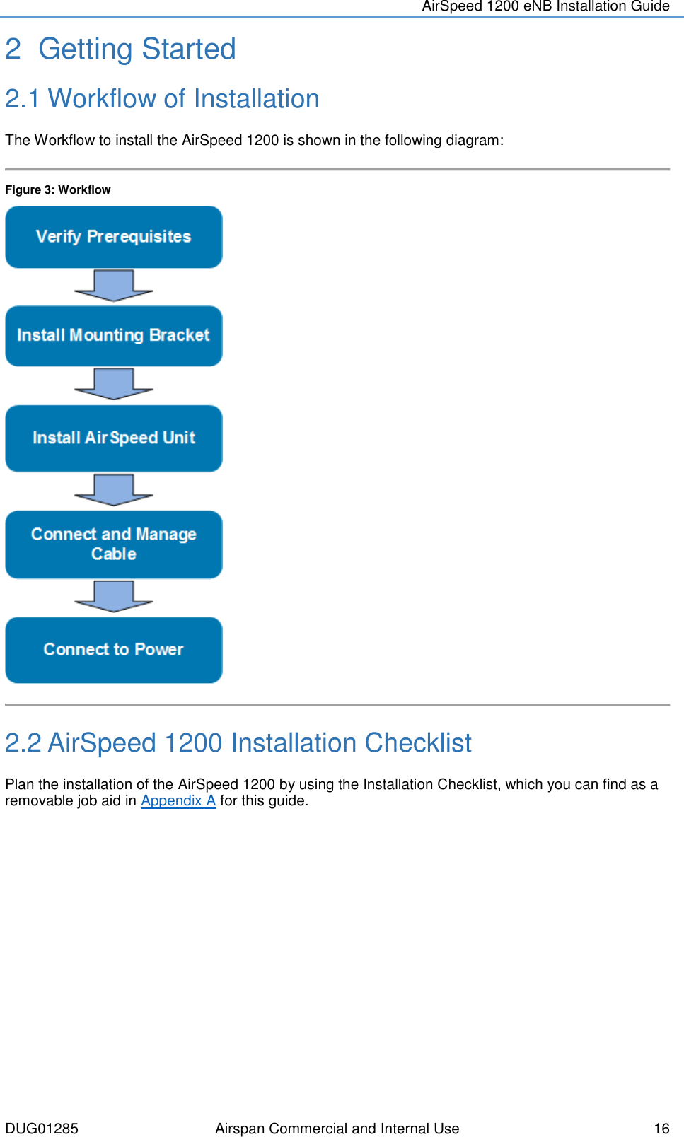
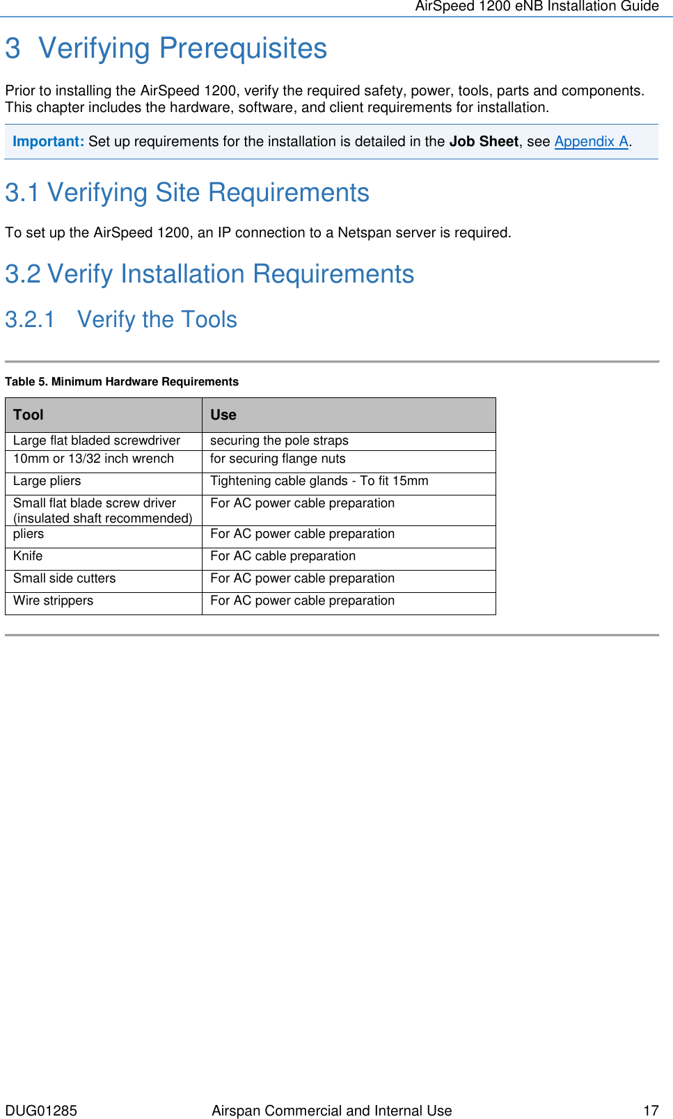
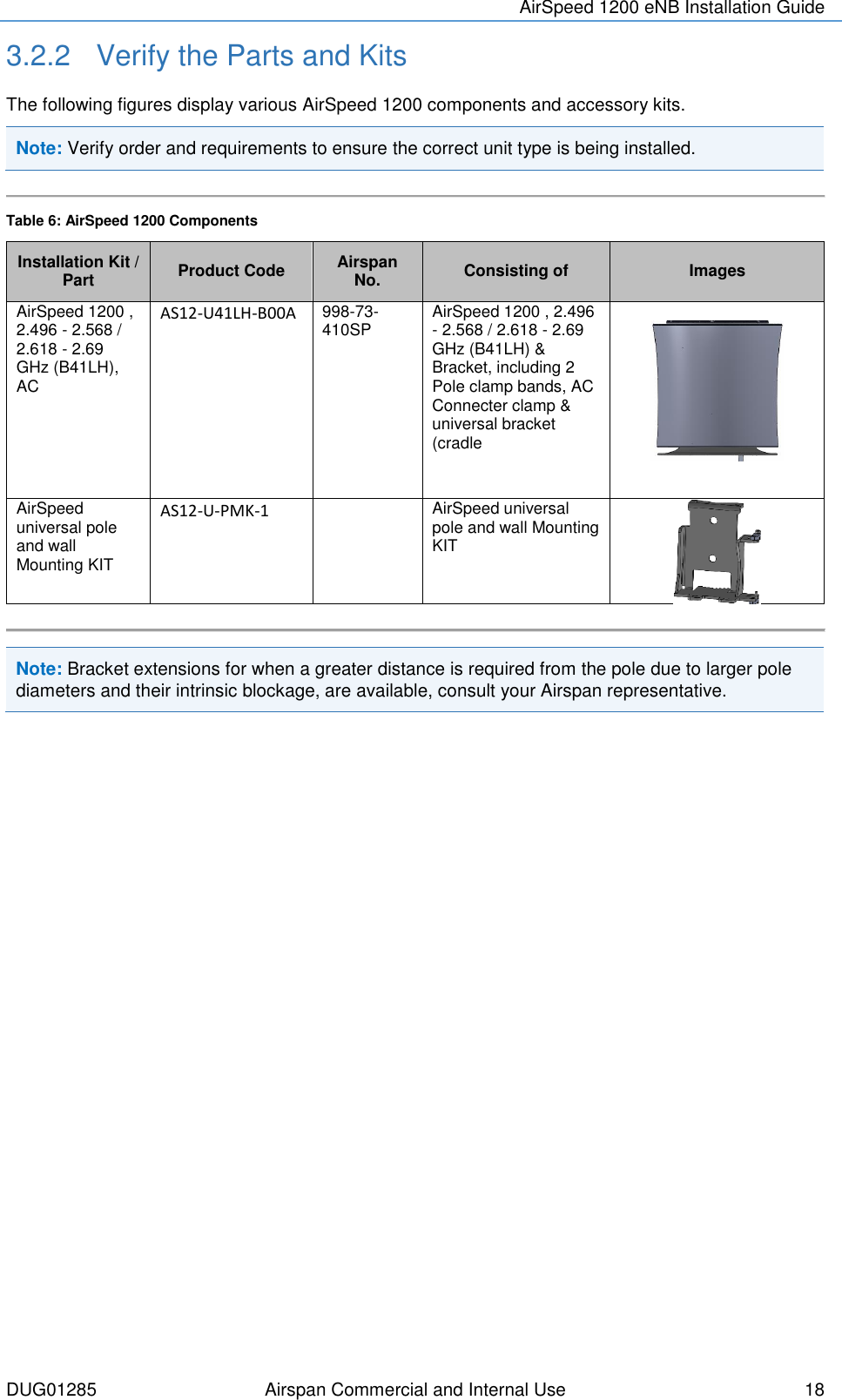
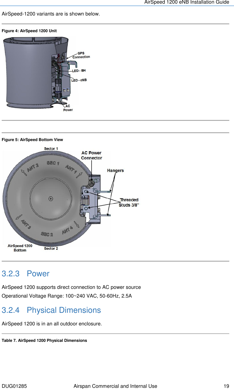
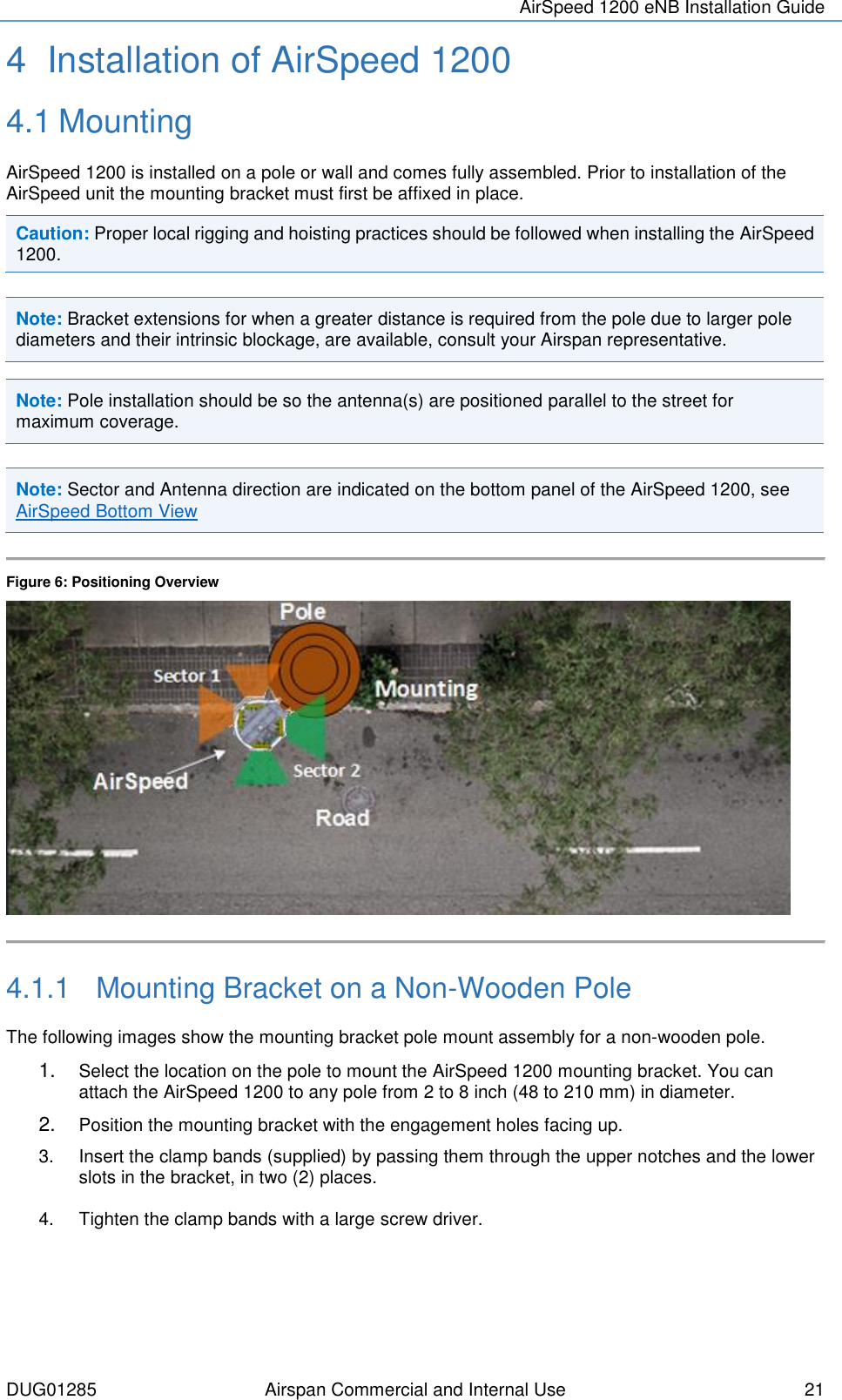
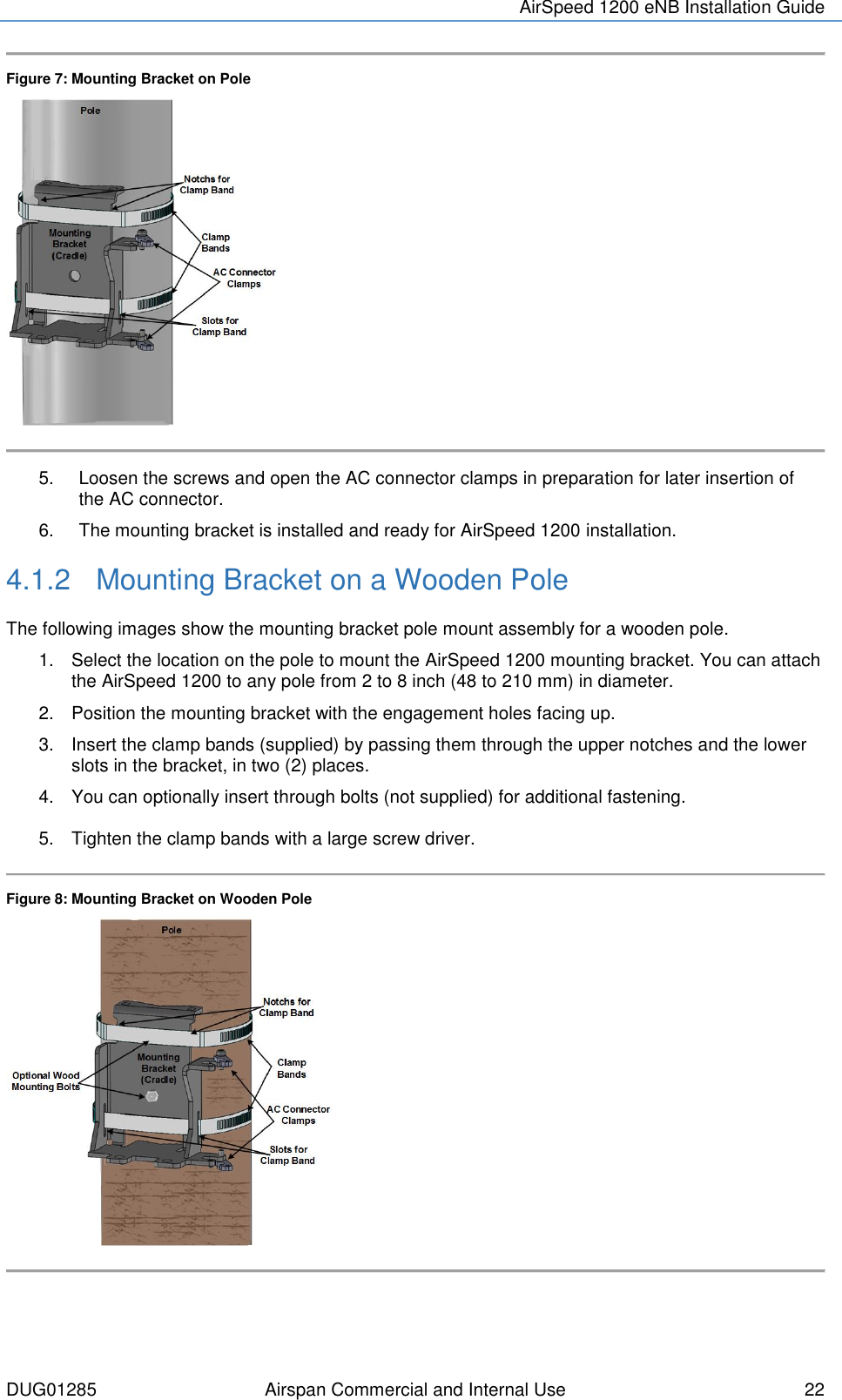
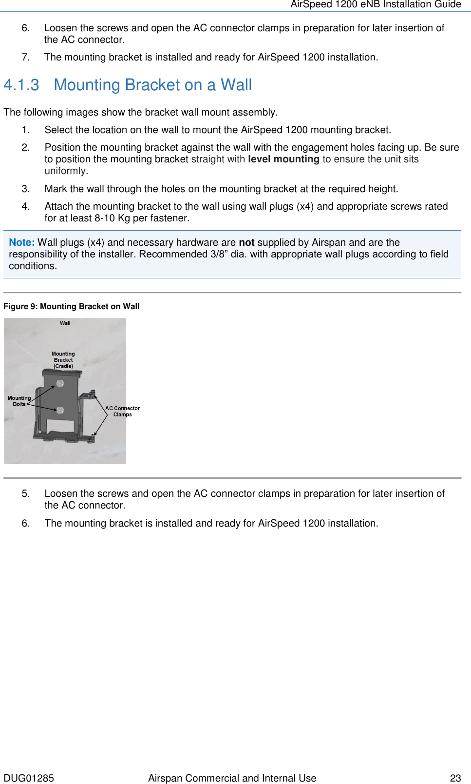
Airspan Networks AS1200 Base station of LTE fixed cellular system User Manual AirSpeed 1200 eNB Installation Guide

Airspan Networks Inc Base station of LTE fixed cellular system AirSpeed 1200 eNB Installation Guide

Users Manual

                      AirSpeed-1200 eNB Installation Guide                Part Number: DUG01285 System Release: 15.5 Revision: AFC Published: August 2017
  © Copyright by Airspan Networks Inc., 2017 - 2017. All rights reserved worldwide. Legal Notices The information contained within this document is proprietary and is subject to all relevant copyright, patent and other laws protecting intellectual property, as well  as  any specific agreements protecting Airspan  Networks Inc.  rights  in  the  aforesaid information. Neither this document nor the information contained herein may be  published, reproduced or disclosed to third parties, in whole or in part, without the express, prior, written permission of Airspan Networks Inc. In addition, any use of this document or the information contained herein for the purposes other than those for which it is disclosed is strictly forbidden. Airspan Networks Inc. reserves the right, without prior notice or liability, to make changes in equipment design or specifications. Information supplied by Airspan Networks Inc. is believed to be accurate and reliable. However, no responsibility is assumed by Airspan Networks Inc. for the use thereof nor for the rights of third parties which may be effected in any way by the use of thereof. Any  representation(s)  in  this  document  concerning  performance  of  Airspan  Networks  Inc.  product(s)  are  for  informational purposes only and are not warranties of future performance, either expressed or implied. Airspan Networks Inc. standard limited warranty, stated in its sales contract or order confirmation form, is the only warranty offered by Airspan Networks Inc. in relation thereto. This document may contain flaws, omissions or typesetting errors; no warranty is granted nor liability assumed in relation thereto unless specifically undertaken in Airspan Networks Inc. sales contract or order confirmation. Information contained herein is periodically updated and changes will be incorporated into subsequent editions. If you have encountered an error, please notify Airspan Networks Inc. All specifications are subject to change without prior notice. Product performance figures quoted within this document are indicative and for information purposes only.  Acknowledgements   © Intel Corporation    http://www.intel.com/   © Microsoft Corporation     http://www.microsoft.com
DUG01285 Airspan Commercial and Internal Use   i  Table of Contents Document Information ............................................................................. 1 Abstract .................................................................................................................. 1 Revision History ..................................................................................................... 1 Warnings and Cautions ........................................................................... 2 Human Exposure to Radio Frequencies ................................................................ 2 Avertissement et Precautions d’Utilisation .............................................. 2 Radio Interference ................................................................................................. 2 Modifications .......................................................................................................... 2 General .................................................................................................................. 2 Général .................................................................................................................. 2  Important Safety Instructions ............................................................................ 3 Safety ..................................................................................................................... 3 Securite .................................................................................................................. 4 Warning of Hazardous Voltages ............................................................................ 4 Attention aux Voltages Hasardeux ......................................................................... 5 Adherence to European Directive 1999/5/EC ........................................................ 5 Warning Symbols ................................................................................................... 5 Service Information ................................................................................................ 5 UL Information ....................................................................................................... 6 Lightning Protection ............................................................................................... 6 Outdoor Ethernet Cabling ...................................................................................... 7 DECLARATION OF CONFORMITY....................................................................... 7 GPS Compliance ................................................................................................... 8 Maximum Output TX Total Power ........................................................... 9 Power Consumption ............................................................................................... 9 Antenna System ................................................................................................... 10 About This Document ........................................................................... 11 Purpose ................................................................................................................ 11 Intended Audience ............................................................................................... 11
AirSpeed 1200 eNB Installation Guide  DUG01285 Airspan Commercial and Internal Use  ii Document Conventions ........................................................................................ 11 Related Reading .................................................................................................. 12 Customer Care Help Desk .................................................................... 13 Airspan Encourages Comments .......................................................................... 13 1 Introduction ....................................................................................... 14 1.1 AirSpeed 1200 .............................................................................................. 14 1.1.1 Deployment .................................................................................................. 14 1.1.2 Integrated Backhaul – LTE UE Relay ........................................................... 14 2 Getting Started .................................................................................. 16 2.1 Workflow of Installation ................................................................................. 16 2.2 AirSpeed 1200 Installation Checklist ............................................................. 16 3 Verifying Prerequisites ...................................................................... 17 3.1 Verifying Site Requirements .......................................................................... 17 3.2 Verify Installation Requirements .................................................................... 17 3.2.1 Verify the Tools ............................................................................................ 17 3.2.2 Verify the Parts and Kits ............................................................................... 18 3.2.3 Power ........................................................................................................... 19 3.2.4 Physical Dimensions .................................................................................... 19 3.2.5 Environmental .............................................................................................. 20 4 Installation of AirSpeed 1200 ............................................................. 21 4.1 Mounting ....................................................................................................... 21 4.1.1 Mounting Bracket on a Non-Wooden Pole .................................................... 21 4.1.2 Mounting Bracket on a Wooden Pole ........................................................... 22 4.1.3 Mounting Bracket on a Wall .......................................................................... 23 4.2 Securing AirSpeed 1200 to the Mounting Bracket ......................................... 24 5 Connecting and Managing Power Cable ........................................... 25 5.1 Power Cable Connection ............................................................................... 25 5.1.1 Power Cable Preparation ............................................................................. 25 5.1.2 Wire Connection for the Power Cable Connector ......................................... 25 A Job Sheet .......................................................................................... 28 B Abbreviations .................................................................................... 30
AirSpeed 1200 eNB Installation Guide  DUG01285 Airspan Commercial and Internal Use  iii  Figures Figure 1: AirSpeed 1200 ....................................................................................................................... 10 Figure 2: AirSpeed 1200 ....................................................................................................................... 15 Figure 3: Workflow ................................................................................................................................ 16 Figure 4: AirSpeed 1200 Unit ................................................................................................................ 19 Figure 5: AirSpeed Bottom View ........................................................................................................... 19 Figure 6: Positioning Overview ............................................................................................................. 21 Figure 7: Mounting Bracket on Pole ...................................................................................................... 22 Figure 8: Mounting Bracket on Wooden Pole ....................................................................................... 22 Figure 9: Mounting Bracket on Wall ...................................................................................................... 23 Figure 10: Securing AirSpeed 1200 to Mounting Bracket ..................................................................... 24 Figure 11: Cable Connector Exploded View ......................................................................................... 25 Figure 12: Cable Preparation ................................................................................................................ 26 Figure 13: Secure Cable to Connector ................................................................................................. 26 Figure 14: Power Cable Assembled ..................................................................................................... 26 Figure 15: Close AC Connector Clamps ............................................................................................... 27 Figure 16: AirSpeed 1200 on Wooden Pole ......................................................................................... 27 Figure 17: AirSpeed 1200 on Non-Wooden Pole ................................................................................. 28 Figure 18: AirSpeed 1200 on Wall ........................................................................................................ 28 Tables   Table 1: AirSpeed 1200 B41 FCC Maximum Output TX Total Power .................................................... 9 Table 2: AirSpeed 1200 B41 ETSI Maximum Output TX Total Power ................................................... 9 Table 3: Power Consumption .................................................................................................................. 9 Table 4: Typographic Conventions ....................................................................................................... 11 Table 5. Minimum Hardware Requirements ......................................................................................... 17 Table 6: AirSpeed 1200 Components ................................................................................................... 18 Table 7. AirSpeed 1200 Physical Dimensions ...................................................................................... 19 Table 8. AirSpeed 1200 Environment Compliance ............................................................................... 20 Table 9: Wire Assignment ..................................................................................................................... 26
AirSpeed 1200 eNB Installation Guide  DUG01285 Airspan Commercial and Internal Use   1  Document Information   Abstract This document details procedures for installing the Airspan’s AirSpeed 1200 Pico-class LTE eNodeB variant.  Revision History Revision Details Date Summary of Changes 0.1 June 2017   Initial document & comments A July 2017   Additions prior to publishing   Additional content from comments AFC1 August 2017   Additions
AirSpeed 1200 eNB Installation Guide  DUG01285 Airspan Commercial and Internal Use  2 Warnings and Cautions Human Exposure to Radio Frequencies The AirSpeed 1200 should be installed and operated from a minimum safe distance of 2.5m Avertissement et Precautions d’Utilisation Exposition des personnes aux fréquences radioélectriques Les antennes d’AirSpeed 1200 doivent être installée et utilisée de façon à garantir la distance minimale de sécurité de 2.5m Radio Interference This AirSpeed 1200 generates, uses, and can radiate radio frequency energy and, if not installed and used in accordance with the instructions, may cause harmful interference to radio communications. However,  there  is  no  guarantee  that  interference  will  not  occur  in  a  particular  installation.  If  this equipment does cause harmful interference to radio or television reception, which can be determined by turning the equipment on and off, the technician is encouraged to try to correct the interference by performing one or more of the following measures:  Re-orientate or relocate the unit    Increase separation between the units and/or End Device   Connect the equipment to a circuit different from that to which the power source is connected Modifications Any changes and modifications to this device that are not expressly approved by Airspan Networks may void the user's authority to operate the equipment. General   Only qualified personnel should be allowed to install, replace, and service the equipment.   The device cannot be sold retail, to the general public or by mail order. It must be sold to operators.   Installation must be controlled.   Installation must be performed by licensed professionals.   Installation requires special training. The AirSpeed 1200 radio and antenna should be installed ONLY by experienced installation professionals who are familiar with local building and safety codes and, wherever applicable, are licensed by the appropriate government regulatory authorities. Failure to do so may void Airspan's product warranty and may expose the end user or the service provider to legal and financial liabilities. Airspan and its resellers or distributors are not liable for injury, damage or violation of regulations associated with the installation of outdoor units or antennas.   The device is to be installed in a Restricted Access Location.   Power provided by PoE output cannot be considered limited power source (LPS) per IEC/UL 60950-1 clause 2.5.   Connection to the PoE port is permitted only by certified electrician according to NEC requirements.    Connect PoE terminal only to equipment which does NOT require “LPS only” feeding. Général
AirSpeed 1200 eNB Installation Guide  DUG01285 Airspan Commercial and Internal Use  3  Seul le personnel qualifié peut être autorisé pour installer ou remplacer l’équipement ainsi qu’effectuer les opérations de maintenance pour cet équipement.  L’équipement ne peut pas être vendu en grande distribution ou par commande via email à destination du public. Il doit être vendu aux opérateurs de télécommunications.   Son installation doit être contrôlée   Son Installation doit être effectuée par des professionnels autorises.   Son installation requiert une formation spécifique du personnel. L’AirSpeed 1200, radio et antenne doit être installe UNIQUEMENT par des installateurs professionnels expérimentés et ayant une connaissance des constructions locales et règles de sécurité, ainsi que, dès que nécessaire, disposant d’un agreement des autorités gouvernementales de régulation. Toute enfreinte a ces obligations peut  annuler la garantie délivrée par Airspan pour ces produits et peut exposer l’utilisateur final ou le fournisseur de services a des dommages légaux et financiers.   Airspan et ses revendeurs ou ses distributeurs ne sont pas responsables des blessures, dommages ou violations de la régulation en vigueur lies a l’installation du système extérieur ou des antennes.  L’Equipment doit être installe dans une zone a accès réduit et contrôle.  L’alimentation fournie par la sortie PoE ne peut pas être considérée comme une Source d’Alimentation Limitée ( ou LPS – limited power source ) selon le standard IEC/UL 60950-1 clause 2.5    La connexion au port PoE est autorisée par un électricien certifie selon les standards NEC.  Connecter le port PoE uniquement aux équipements NE demandant PAS un source de type ‘’ LPS only  Important Safety Instructions   Read and Save these instructions   This Installation Guide contains instructions and warnings that should be followed during installation, and operation.    Failure to follow these instructions could cause bodily injury and/or product failure. Safety  1.  Read this guide and follow all operating and safety instructions. 2.  Supply cord is not shipped with the unit and is to be provided by user. Installation is to be performed by a qualified electrician according to local codes. Installation to be done in accordance with the National Electrical Code (NEC), ANSI/NFPA 70, the Canadian Electrical Code (CEC), Part I, CAN/CSA C22.1, and when applicable, the National Electrical Safety Code, IEEE C2. 3.  Static sensitive components inside - do not remove the lid or base: No user serviceable parts inside. 4.  The ground connection should be made before connecting to supply connections. 5.  Position the power cord to avoid possible damage; do not overload circuits. 6.  Do not place this product on or near a direct heat source, and avoid placing objects on the terminal. 7.  To avoid electrical shock do not install this device during adverse conditions such as rain or inclement weather. 8.  Use only a damp cloth for cleaning. Do not use liquid or aerosol cleaners. Disconnect the power before cleaning. 9.  The units should not be located too near power lines or other electrical power circuits, where it can come into contact with such power lines or circuits.
AirSpeed 1200 eNB Installation Guide  DUG01285 Airspan Commercial and Internal Use  4 10.  The radio transceiver must be properly grounded to protect against power surges and accumulated static electricity. It is the user’s responsibility to install this device in accordance with the local electrical codes. 11.  Installation of the AirSpeed 1200 must be contracted to a professional installer.  12.  The circuit breaker should be easily accessible in case you have to disconnect the device. 13.  When installed in the final configuration, the product must comply with the applicable Safety Standards and regulatory requirements of the country in which it is installed. If necessary, consult with the appropriate regulatory agencies and inspection authorities to ensure compliance. Securite 1.  Lire attentivement ce guide et suivre les instructions d’utilisation et de sécurité. 2. Le cordon d’alimentation n’est pas livré avec l'appareil et doit être fourni par l'utilisateur. L’installation doit être effectuée par un électricien qualifié conformément aux règles et standards locaux. L’installation doit être effectuée en conformité avec le Code national de l'électricité ( NEC ), ANSI / NFPA 70, le Code canadien de l'électricité (CCE ), Partie I, CAN / CSA C22.1, et le cas échéant, le Code national de sécurité électrique, IEEE C2. 3. Des composants sensibles a électricité statique sont utilisés à l’intérieur. Ne pas retirer le coffre ou la base. Aucune pièce a l’intérieur est d’utilité pour l’utilisateur. 4.  La connexion "terre" doit être effectuée en priorité et avant d'effectuer les connexions à la source d'alimentation (phase et neutre). 5. Positionner le cordon d’alimentation de façon à éviter des dommages potentiels. Ne pas surcharger les circuits. 6. Ne pas placer ce produit sur ou à proximité d’une source directe de chaleur et éviter de placer des objets sur le terminal. 7. Afin d’éviter des problèmes électriques, ne pas installer cet équipement au cours d’évènements climatiques difficiles comme averses ou météo non clémente. 8.  Utiliser uniquement chiffon de coton pour nettoyage. Ne pas utiliser de produits liquides ou d’aérosols. Déconnecter le produit de la source d’alimentation avant nettoyage. 9. L’unité ne doit pas être située trop près de lignes électriques ou autres circuits de puissance, avec lesquels il pourrait entrer en contact. 10. L’émetteur radio doit être correctement relie a la terre afin de le protéger contre les surtensions ou accumulation d’électricité statique. L’utilisateur est tenu responsable de l’installation du produit conformément aux règles électrique en vigueur localement. 11. L’installation de AirSpeed 1200 doit être contractualisée avec un installateur professionnel. 12. L’interrupteur de circuit électrique doit être facilement accessible afin de pouvoir déconnecter l’équipement. 13.  Lors de l’installation de la configuration finale, le produit doit être conforme aux Standards de Sécurité en vigueur ainsi qu’aux exigences réglementaires du pays dans lequel il est installé. Si nécessaire, consulter les agences règlementaires appropriées, ainsi que les autorités chargées de l’inspection afin de garantir la conformité. Warning of Hazardous Voltages On AC installations, hazardous voltages exist.  Use caution when verifying or working with AC power.  Remove metal jewellery that could come into contact with AC power. On DC sections, short-circuiting the low voltage, low impedance circuits can cause severe arcing that may result in burns or eye damage.  Remove rings, watches etc. to avoid shorting DC circuits.
AirSpeed 1200 eNB Installation Guide  DUG01285 Airspan Commercial and Internal Use  5 Note: Airspan products do not contain hazardous substances (as defined in UK Control of Substances Hazardous to Health Regulations 1989 and the Dangerous Substances Regulations 1990).  At the end of any Airspan products life cycle, the customer should consult with Airspan to ensure that the product is disposed of in conformance with the relevant regulatory requirements. Attention aux Voltages Hasardeux Sur  les  installations  de  réseau  électrique  de  type  courant  alternatif  (CA)  des  voltages  hasardeux peuvent  survenir.  Garder  une  Attention  particulière  lors  d’une  vérification ou de travaux  sur réseau électrique CA. Retirer tous bijoux en métal qui pourraient entrer en contact avec l’alimentation ou le réseau CA. Sur les portions de réseau électrique de type courant continu (CC), un circuit basse impédance peut causer de sérieux arcs  électriques qui pourraient bruler  ou endommager les yeux. Retirer bagues, anneaux, montres etc… afin d’éviter les court-circuit sur le réseau CC. Adherence to European Directive 1999/5/EC European Council Recommendation 1999/5/EC details basic restrictions and reference levels on human exposure to electromagnetic fields as advised by the ICNIRP. Adherence to these recommended restrictions and reference levels should provide a high level of protection as regards the established health effects that may result from exposure to electromagnetic fields.  Airspan  equipment  is  compliant  with  CE  and  R&TTE  regulations  and  can  be  operated  in  all  EU (European Union) locations listed below: Country Code BE EL LT PT BG ES LU RO CZ FR HU SI DK HR MT SK DE IT NL FI EE CY AT SE IE LV PL UK Warning Symbols The following symbols may be encountered during installation or troubleshooting. These warning symbols mean danger. Bodily injury may result if you are not aware of the safety hazards involved in working with electrical equipment and radio transmitters. Familiarize yourself with standard safety practices before continuing.     Caution, hot surface Caution Electro-Magnetic Radiation High Voltage Service Information
AirSpeed 1200 eNB Installation Guide  DUG01285 Airspan Commercial and Internal Use  6 Refer all repairs to qualified service personnel. Do not modify any part of this device, as this will void the warranty. Disconnect the power to this product and return it for service if the following conditions apply: a.  The terminal does not function after following the operating instructions outlined in this manual. b.  The product has been dropped or the housing is damaged. Locate the serial number of the terminal and record this on your registration card for future reference. Also record the MAC address, located on the product sticker. UL Information - The equipment must be properly grounded according with NEC and other local safety code requirements. - Reminder to all the BWA system installers: Attention to Section 820-40 of the NEC which provides guidelines for proper grounding and, in particular, specifies that the cable ground shall be connected to the grounding system of the building, as close to the point of cable entry as is practical. - AirSpeed 1200 is designed to operate in environmental conditions complying with IP66 and relevant standards. Lightning Protection WARNING: The following notes are general recommendations for the system. The wireless equipment should be installed by a qualified professional installer and must follow local and national codes for electrical  grounding  and  safety.  Failure  to  meet  safety  requirements  and/or  use  of  non-standard practices and procedures could result in personal injury and damage to equipment. A direct lightning strike may cause serious damage even if these guidelines are followed. All outdoor wireless equipment is susceptible to lightning damage from a direct hit or induced current from a near strike. Lightning protection and grounding practices in local and national electrical codes serve to minimize equipment damage, service outages, and serious injury. The antennas are to be DC grounded, so surge protection is not required. Reasons for lightning damage are summarized as: - Poorly grounded tower/antenna sites that can conduct high lightning strike energy into equipment. -  Lack  of  properly  installed  lightning  protection  equipment  that  can  cause  equipment  failures  from lightning induced currents. A lighting protection system provides a means by which the energy may enter earth without passing through and damaging parts of a structure. A lightning protection system does not prevent lightning from striking; it provides a means for controlling it and preventing damage by providing a low resistance path for the discharge of energy to travel safely to ground. Improperly grounded connections are also a source of noise that can cause sensitive equipment to malfunction. A good tower grounding system disperses most of the surge energy from a tower strike away from the building and equipment. To limit the equipment damage due to a lightning strike, the following practices are recommended for the wireless system: -  Provide  direct  grounding  from  the  antenna  mounting  bracket,  the  radio  and  antenna  and  the lightning/surge protectors to the same ground point at the base of the tower or a ground bus on the building. Use the grounding screws on the antenna bracket and the radio and antenna for terminating the ground wires. - The circuit ground must be connected to the same grounding system as the eNodeB.
AirSpeed 1200 eNB Installation Guide  DUG01285 Airspan Commercial and Internal Use  7 Outdoor Ethernet Cabling - Ethernet cable connected to should be outdoor grade with UV protection. - Use shielded out CAT6 cabled terminated with metallic RJ45 connectors. - In order to protect the indoor unit, install surge protection circuits on all copper cables on their entrance to the building. - Surge protection circuit must use a minimum 14AWG grounding cable. DECLARATION OF CONFORMITY European Community, Switzerland, Norway, Iceland, and Liechtenstein  Declaration of Conformity with Regard to the R&TTE Directive 1999/5/EC English:  This  equipment  is  in  compliance  with  the  essential  requirements  and  other  relevant  provisions  of Directive 1999/5/EC.  Deutsch:  Dieses  Gerät  entspricht  den  grundlegenden  Anforderungen  und  den  weiteren  entsprecheneden Vorgaben der Richtlinie 1999/5/EU.   Dansk:  Dette udstyr er i overensstemmelse med de væsentlige krav og andre relevante bestemmelser i Directiv 1999/5/EF.   Español:  Este equipo cumple con los requisitos esenciales asi como con otras disposiciones de la Directive 1999/5/EC.   Greek:  ΜΕ  ΤΗΝ ΠΑΡΟΥΣΑ  Airspan  ΔΗΛΩΝΕΙ  ΟΤΙ  Ο  ΕΞΟΠΛΙΣΜΟΣ  ΣΥΜΜΟΡΦΩΝΕΤΑΙ  ΠΡΟΣ  ΤΙΣ ΟΥΣΙΩΔΕΙΣ ΑΠΑΙΤΗΣΕΙΣ ΚΑΙ ΤΙΣ ΛΟΙΠΕΣ ΣΧΕΤΙΚΕΣ ΔΙΑΤΑΞΕΙΣ ΤΗΣ ΟΔΗΓΙΑΣ 1999/5/ΕΚ.   Français:  Cet appareil  est conforme aux exigencies  essentialles  et  aux  autres  dispositions  pertinantes  de la Directive 1999/5/EC.   Íslenska:  Þessi búnaður samrýmist lögboðnum kröfum og öðrum ákvæðum tilskipunar 1999/5/ESB.   Italiano:  Questo apparato é conforme ai requisiti essenziali ed agli altri principi sanciti dalla Direttiva 1999/5/EC.   Nederlands:  Deze apparatuur voldoet aan de belangrijkste eisen en andere voorzieningen van richtlijn 1999/5/EC.   Norsk:  Dette utstyret er i samsvar med de grunnleggende krav og andre relevante bestemmelser i EU-directiv 1999/5/EC.   Português:  Este equipamento satisfaz os requisitos essenciais e outras provisões da Directiva 1999/5/EC.   Suomalainen:  Tämä laite täyttää direktiivin 1999/5/EY oleelliset vaatimukset ja on siinä asetettujen muidenkin ehtojen mukainen.
AirSpeed 1200 eNB Installation Guide  DUG01285 Airspan Commercial and Internal Use  8 Svenska:  Denna utrustning är i överensstämmelse med de väsentliga kraven och andra relevanta bestämmelser i Direktiv 1999/5/EC. Român: Acest echipament este în conformitate cu cerinţele esenţiale şi alte prevederi relevante ale Directivei 1999/5/CE.  The Declaration of Conformity related to this product can be obtained from PLM@Airspan.com. GPS Compliance The GPS is in compliance with the essential requirements and other relevant provisions of Directive 1999/5/EC." The GPS complies with the following EMC Common Regulatory Testing standards:   EN55022: Radiated and Conducted Emissions   CISPR 22: Class B   EN 50081-1: Generic Emissions Class B   EN 50082-1: Generic Immunity Class B   EN 61000-4-2: Electrostatic Discharge Immunity   EN 61000-4-3: Radiated RF EM Field Immunity Test   EN 61000-4-4: Electrical Fast Transient/Burst Test   EN 61000-4-6: Conducted Immunity   EN 61000-4-8: Magnetic Field Immunity Note: A GPS is recommended for synchronizing between LTE sectors.  Note: An optional GPS Lightning/Surge protector is available from Airspan when installing the GPS antenna in a remote location for lightning prone deployments.
AirSpeed 1200 eNB Installation Guide  DUG01285 Airspan Commercial and Internal Use  9 Maximum Output TX Total Power  Table 1: AirSpeed 1200 B41 FCC Maximum Output TX Total Power Frequency Band (MHz) FCC TX                  EIRP Antenna Gain 2496 – 2690 28.32 dBm 38.82 dBm 10.5 dBi   Table 2: AirSpeed 1200 B41 ETSI Maximum Output TX Total Power Frequency Band (MHz) ETSI TX                  EIRP Antenna Gain 2496 – 2690 MHz 28 dBm 38.5 dBm 10.5 dBi  Caution: Do not set maximum output TX power to higher than local regulations. Power Consumption AirSpeed 1200 has a Max nominal power consumption of 50W. AirSpeed 1200 power consumption is described in the following table:  Table 3: Power Consumption Duplex Tx Power at RF Port (dBm) Nominal Power Consumption (W) TDD Sec1: 25 Sec2: 41 50
AirSpeed 1200 eNB Installation Guide  DUG01285 Airspan Commercial and Internal Use  10 Antenna System The AirSpeed 1200 provides the best SINR levels toward the donor MACRO eNodeB.  Figure 1: AirSpeed 1200
AirSpeed 1200 eNB Installation Guide  DUG01285 Airspan Commercial and Internal Use  11 About This Document Purpose This guide provides the workflow and step-by-step procedures for Installing the AirSpeed 1200.  These procedures include:   Verify prerequisites   Install the AirSpeed 1200   Connect and manage cables Intended Audience This guide is intended for persons who are responsible for installing the AirSpeed 1200 equipment. These persons should have a working knowledge of the equipment. Document Conventions This document uses the following typographic conventions.  Table 4: Typographic Conventions Convention Element Blue underlined text  Cross-reference links. Bold text Keyboard buttons and GUI elements. Command Command names or phrases. Computer output Text displayed by the computer. Hyperlinks Website and e-mail addresses. Danger Signifies a hazardous situation—if not avoided—will cause death or serious injury. Describes how to avoid it. Warning Signifies a hazardous situation—if not avoided—can cause death or serious personal injury. Describes how to avoid it.  Caution Signifies a hazardous situation—if not avoided—can void the product warranty, and cause property damage. Describes how to avoid it. Important Provides necessary information to explain a task. Note Provides additional information. Tip Provides helpful hints.
AirSpeed 1200 eNB Installation Guide  DUG01285 Airspan Commercial and Internal Use  12 Related Reading The following documents contain related information:   AirSpeed 1200 Product Datasheet  Airspan LTE Commissioning Manual Pending
AirSpeed 1200 eNB Installation Guide  DUG01285 Airspan Commercial and Internal Use  13 Customer Care Help Desk Airspan’s Customer Care Help Desk offers prompt and efficient customer support services. Note: To avail Airspan’s Customer Care Help Desk support, you must be a registered user and must have a valid support contract. To register, click here and fill the Registration form. To create and update issue logs, send e-mails to Customer Care Help Desk. Once you submit your issue, the system generates a new issue and sends an issue number for your reference. The system uses this issue number to categorize and store e-mails under the appropriate issue. To help Customer Care Help Desk identify your issue, include the issue number and your Customer Care Helpdesk account details in all further communications. Main Operations Airspan Communications Ltd.  Capital Point  33 Bath Road  Slough, Berkshire  SL1 3UF, United Kingdom  Tel: +44-1895-467-100  Worldwide Headquarters Airspan Networks Inc. 777, Yamato Road, Suite 105 Boca Raton, FL 3341-4408, USA Tel: +1 561 893 8670 Airspan Encourages Comments Airspan welcomes any feedback and suggestions that help to improve the quality of the documentation. Send your feedback to documentfeedback@airspan.com.
AirSpeed 1200 eNB Installation Guide  DUG01285 Airspan Commercial and Internal Use  14 1  Introduction This section provides a descriptive overview of the Airspan’s AirSpeed 1200 Pico-class eNodeB variant and its place in the Airspan product suite.  1.1 AirSpeed 1200 AirSpeed 1200 is part of Airspan’s carrier-class LTE advanced outdoor small cell eNodeB family. AirSpeed 1200 is a Pico-class LTE eNodeB product, providing high-speed data, mobility, Voice over LTE, and broadcast/multicast services. AirSpeed 1200 is a super compact, easy to install Pico-class eNodeB. Allowing an operator to deploy LTE broadband services on any Street Furniture, rooftop or building front without the need for backhaul connectivity or infrastructure – It uses the already existing Macro layer for backhauling. AirSpeed 1200 is a dual sector / carrier 2x2 MIMO product. AirSpeed 1200 fully supports the standard LTE (Uu/S1/X2) interfaces. All Airspan eNodeB products, including AirSpeed 1200, are interoperable with a rich portfolio of 3rd party end user devices, including many handsets, indoor UEs, outdoor UEs and USB dongles from several ODMs, using various chipsets. For an updated of interoperability list, please contact your nearest Airspan Sales Representative. Note: For management please refer to the AirSpan LTE Commissioning Manual as well as the Netspan User Manual. 1.1.1  Deployment AirSpeed 1200 perfectly fits the requirements of the hard zoning outdoor locations such as hotels, city centers, parks and universities all due to its super compact one box form factor.   AirSpeed 1200 creates a single install process for LTE Access and Backhaul, and enables “Just add Power”  plug  and play  deployment method and  along with  the  easy  zoning  of the  product  saving deployment related costs and time.   Note: The following is for illustration only; actual layout may differ as infrastructure is installation-specific.  Note: AirSpeed 1200 must be properly grounded according with NEC and other local safety code requirements.  1.1.2  Integrated Backhaul – LTE UE Relay AirSpeed 1200 includes an integrated wireless backhaul using an innovative LTE UE Relay technology using the Macro layer for backhauling.
AirSpeed 1200 eNB Installation Guide  DUG01285 Airspan Commercial and Internal Use  15  Figure 2: AirSpeed 1200   Note: The illustration above displays the AirSpeed 1200 unit.
AirSpeed 1200 eNB Installation Guide  DUG01285 Airspan Commercial and Internal Use  16 2  Getting Started 2.1 Workflow of Installation The Workflow to install the AirSpeed 1200 is shown in the following diagram:   Figure 3: Workflow   2.2 AirSpeed 1200 Installation Checklist Plan the installation of the AirSpeed 1200 by using the Installation Checklist, which you can find as a removable job aid in Appendix A for this guide.
AirSpeed 1200 eNB Installation Guide  DUG01285 Airspan Commercial and Internal Use  17 3  Verifying Prerequisites Prior to installing the AirSpeed 1200, verify the required safety, power, tools, parts and components. This chapter includes the hardware, software, and client requirements for installation. Important: Set up requirements for the installation is detailed in the Job Sheet, see Appendix A.  3.1 Verifying Site Requirements To set up the AirSpeed 1200, an IP connection to a Netspan server is required. 3.2 Verify Installation Requirements 3.2.1  Verify the Tools  Table 5. Minimum Hardware Requirements Tool Use Large flat bladed screwdriver  securing the pole straps 10mm or 13/32 inch wrench  for securing flange nuts Large pliers  Tightening cable glands - To fit 15mm Small flat blade screw driver (insulated shaft recommended) For AC power cable preparation pliers  For AC power cable preparation Knife For AC cable preparation Small side cutters For AC power cable preparation Wire strippers For AC power cable preparation
AirSpeed 1200 eNB Installation Guide  DUG01285 Airspan Commercial and Internal Use  18 3.2.2  Verify the Parts and Kits The following figures display various AirSpeed 1200 components and accessory kits. Note: Verify order and requirements to ensure the correct unit type is being installed.  Table 6: AirSpeed 1200 Components Installation Kit / Part Product Code Airspan No. Consisting of Images AirSpeed 1200 , 2.496 - 2.568 / 2.618 - 2.69 GHz (B41LH), AC AS12-U41LH-B00A 998-73-410SP AirSpeed 1200 , 2.496 - 2.568 / 2.618 - 2.69 GHz (B41LH) & Bracket, including 2 Pole clamp bands, AC Connecter clamp & universal bracket (cradle     AirSpeed universal pole and wall Mounting KIT AS12-U-PMK-1  AirSpeed universal pole and wall Mounting KIT   Note: Bracket extensions for when a greater distance is required from the pole due to larger pole diameters and their intrinsic blockage, are available, consult your Airspan representative.
AirSpeed 1200 eNB Installation Guide  DUG01285 Airspan Commercial and Internal Use  19 AirSpeed-1200 variants are is shown below.  Figure 4: AirSpeed 1200 Unit     Figure 5: AirSpeed Bottom View   3.2.3  Power AirSpeed 1200 supports direct connection to AC power source Operational Voltage Range: 100~240 VAC, 50-60Hz, 2.5A  3.2.4  Physical Dimensions AirSpeed 1200 is in an all outdoor enclosure.  Table 7. AirSpeed 1200 Physical Dimensions
AirSpeed 1200 eNB Installation Guide  DUG01285 Airspan Commercial and Internal Use  20 Variant Dimensions (H x D) Comment Total size 260 x 200 - 230 mm / 10.24 x 8-9 in. The physical dimensions exclude connectors Weight Main Unit 4.6 Kg / 10.14 Lbs.  Universal mounting bracket (cradle) 1 Kg / 2.2 Lbs.   3.2.5  Environmental Note: AirSpeed 1200 is not meant to be used in a Marine environment.  AirSpeed 1200 meets the following environmental requirements:  GR-63 Storage and Transportation   ETSI EN 300-019-1-4 Operational (non-weather protected equipment)   ETSI EN 300-019-1-1 Storage (weather protected, not temperature controlled locations)   ETSI EN 300-019-1-2 Transportation  Table 8. AirSpeed 1200 Environment Compliance Type Details Operating temperature -40°C to 55°C / -40°F to 131°F Operating humidity 5% - 100% non-condensing Storage temperature -40°C to 70° C / -40°F to 158°F Storage humidity 5% - 100% non-condensing Rain and dust ingress protection IP66
AirSpeed 1200 eNB Installation Guide  DUG01285 Airspan Commercial and Internal Use  21 4  Installation of AirSpeed 1200 4.1 Mounting AirSpeed 1200 is installed on a pole or wall and comes fully assembled. Prior to installation of the AirSpeed unit the mounting bracket must first be affixed in place. Caution: Proper local rigging and hoisting practices should be followed when installing the AirSpeed 1200.  Note: Bracket extensions for when a greater distance is required from the pole due to larger pole diameters and their intrinsic blockage, are available, consult your Airspan representative.  Note: Pole installation should be so the antenna(s) are positioned parallel to the street for maximum coverage.  Note: Sector and Antenna direction are indicated on the bottom panel of the AirSpeed 1200, see AirSpeed Bottom View  Figure 6: Positioning Overview   4.1.1  Mounting Bracket on a Non-Wooden Pole The following images show the mounting bracket pole mount assembly for a non-wooden pole. 1. Select the location on the pole to mount the AirSpeed 1200 mounting bracket. You can attach the AirSpeed 1200 to any pole from 2 to 8 inch (48 to 210 mm) in diameter. 2. Position the mounting bracket with the engagement holes facing up. 3.  Insert the clamp bands (supplied) by passing them through the upper notches and the lower slots in the bracket, in two (2) places.  4.  Tighten the clamp bands with a large screw driver.
AirSpeed 1200 eNB Installation Guide  DUG01285 Airspan Commercial and Internal Use  22  Figure 7: Mounting Bracket on Pole   5.  Loosen the screws and open the AC connector clamps in preparation for later insertion of the AC connector. 6.  The mounting bracket is installed and ready for AirSpeed 1200 installation. 4.1.2  Mounting Bracket on a Wooden Pole The following images show the mounting bracket pole mount assembly for a wooden pole. 1.  Select the location on the pole to mount the AirSpeed 1200 mounting bracket. You can attach the AirSpeed 1200 to any pole from 2 to 8 inch (48 to 210 mm) in diameter. 2.  Position the mounting bracket with the engagement holes facing up. 3.  Insert the clamp bands (supplied) by passing them through the upper notches and the lower slots in the bracket, in two (2) places. 4.  You can optionally insert through bolts (not supplied) for additional fastening.  5.  Tighten the clamp bands with a large screw driver.  Figure 8: Mounting Bracket on Wooden Pole
AirSpeed 1200 eNB Installation Guide  DUG01285 Airspan Commercial and Internal Use  23 6.  Loosen the screws and open the AC connector clamps in preparation for later insertion of the AC connector. 7.  The mounting bracket is installed and ready for AirSpeed 1200 installation. 4.1.3  Mounting Bracket on a Wall The following images show the bracket wall mount assembly. 1.  Select the location on the wall to mount the AirSpeed 1200 mounting bracket. 2.  Position the mounting bracket against the wall with the engagement holes facing up. Be sure to position the mounting bracket straight with level mounting to ensure the unit sits uniformly. 3.  Mark the wall through the holes on the mounting bracket at the required height. 4.  Attach the mounting bracket to the wall using wall plugs (x4) and appropriate screws rated for at least 8-10 Kg per fastener. Note: Wall plugs (x4) and necessary hardware are not supplied by Airspan and are the responsibility of the installer. Recommended 3/8” dia. with appropriate wall plugs according to field conditions.  Figure 9: Mounting Bracket on Wall   5.  Loosen the screws and open the AC connector clamps in preparation for later insertion of the AC connector. 6.  The mounting bracket is installed and ready for AirSpeed 1200 installation.
AirSpeed 1200 eNB Installation Guide  DUG01285 Airspan Commercial and Internal Use  24 4.2 Securing AirSpeed 1200 to the Mounting Bracket The following procedure describes assembly of the AirSpeed 1200 on the mounting bracket (cradle). This procedure is applicable to all mounting scenarios, pole or wall. 1.  Lift the AirSpeed 1200 unit on to the mounting bracket and align the hangers with their respective slots on the top portion of the bracket. 2.  Insert the hangers into the top slots of the mounting bracket. 3.  With the hangers engaged in the top slots align the threaded (M8) studs (that protrude from the bottom of the unit) into the bottom holes of the mounting bracket and fasten the supplied M8 washer and flange nut. 4.  Tighten the M8 flange nuts (2 places).  Figure 10: Securing AirSpeed 1200 to Mounting Bracket   The AirSpeed 1200 is installed and ready for power cable connection. Assembly of the power cable and the power cable connector clamp are described in  Power Cable Preparation below.
AirSpeed 1200 eNB Installation Guide  DUG01285 Airspan Commercial and Internal Use  25 5  Connecting and Managing Power Cable 5.1  Power Cable Connection Danger: Hazardous voltage!  Before working, ensure that the power is removed from the power connection cables.  When the system is powered on, do not touch the power terminals. 5.1.1  Power Cable Preparation Tip: It is good practice to label both ends of the cable to identify which AirSpeed 1200 unit it is connected to.  Tip: It is good practice to leave a spare loop of cable (approximately 0.5m). This will allow for easier wiring and will allow the cable to be re-terminated if necessary in the future.  Warning: Required:  - Circuit breaker for AC power source -16A for EU installation and 20A for US installation. Minimum – 10A. The power cable is connected to the AirSpeed 1200 connector on the back panel of the unit.  Figure 11: Cable Connector Exploded View   Note: When securing the cable make sure there is no tension on the cable so that it is easy to disconnect and re-connect for future maintenance actions. 5.1.2  Wire Connection for the Power Cable Connector 1.  Unscrew the connector lower section of the connector which is attached to the cable on the AirSpeed 1200 unit. 2.  Feed the unterminated end of the power cable to the location of the AC Power Connector suspended from the AirSpeed unit. 3.  Strip back and remove the outer sheath to expose the inner blue / white and black insulated wires to a length of 3cm (1.18 in). Then strip back 6mm (0.24 in) of the inner core insulation. 4.  Thread the prepared cable end through the gland, washer, sealing ring and body of the connector.
AirSpeed 1200 eNB Installation Guide  DUG01285 Airspan Commercial and Internal Use  26  Figure 12: Cable Preparation   5.  Secure the prepared ends of the cable into the inner part of the connector.  Figure 13: Secure Cable to Connector    6.  Line up the attached cable in preparation for closing the connector housing sections. Do not tighten the tail nut yet.  Figure 14: Power Cable Assembled   7.  Once assembled tighten the tail nuts.  Table 9: Wire Assignment Wire Color Description White Neutral Black Phase Green Ground  1.  Insert into connector, and screw shut. 2.  Tighten the tail nut on to the body forcing the seal to compress around the power cable ends. Caution: Do not over tighten the connector or the tail nut. The connector nut should be tightened to a torque of no more than 3.3 Nm (2.43 lb-ft) max.   Note: When securing the cable verify there is no tension on the connector so that it is easy to disconnect and re-connect for future maintenance actions.   3.  Gently re-position the AC Connector so the AC Connector Clamps close onto the power cable holding it in place.
AirSpeed 1200 eNB Installation Guide  DUG01285 Airspan Commercial and Internal Use  27  Figure 15: Close AC Connector Clamps   4.  Secure the AC clamp screws. 5.  The AirSpeed 1200 is installed and ready for power cable connection. AirSpeed 1200 mounted on a wooden pole.  Figure 16: AirSpeed 1200 on Wooden Pole
AirSpeed 1200 eNB Installation Guide  DUG01285 Airspan Commercial and Internal Use  28 AirSpeed 1200 mounted on a non-wooden pole.  Figure 17: AirSpeed 1200 on Non-Wooden Pole   AirSpeed 1200 mounted on a wall.  Figure 18: AirSpeed 1200 on Wall    A Job Sheet This job sheet enables the users to keep track of their installation. It covers all the prerequisites required for accomplishing the AirSpeed 1200 installation.   Site Requirements  o  Pole or Wall for installation identified o  Position on pole or Wall identified o  Access restrictions (highway regulations, other services on pole, power pole) o  Method of reaching desired positions (ladders, Elevated work platform) o  AC main fuse block available (where needed) o  Configuration programming details known o  All equipment items available at the installation site
AirSpeed 1200 eNB Installation Guide  DUG01285 Airspan Commercial and Internal Use  29 o  Main AirSpeed 1200 unit o  AC Connector Clamp Tool Requirements (For further information, see Verify the Tools.) o  Large flat screw driver for pole clamps o  Small flat blade screw driver (insulated shaft recommended) o  Medium Philips head screw driver o  8mm wrench for unit nuts o  Knife o  pliers o  Small side cutters o  Tweezers (or fine blade long nose pliers) o  Wire strippers Required Ancillary Equipment o  Laptop PC for initial configuration o  cable for temporary connection of the lap top
AirSpeed 1200 eNB Installation Guide  DUG01285 Airspan Commercial and Internal Use  30 B  Abbreviations Term Definition 3GPP 3rd Generation Partnership Project, responsible for LTE ABS Almost Blank Subframe ACS Adjacent Channel Selectivity is a measurement of a receiver's ability to process a desired signal while rejecting a strong signal in an adjacent frequency channel. ACS is defined as the ratio of the receiver filter attenuation on the assigned channel frequency to the receiver filter attenuation on the adjacent channel frequency. AWGN Additive White Gaussian Noise is a channel model in which the only impairment to communication is a linear addition of white noise with a constant spectral density and a Gaussian distribution of amplitude. BER Bit Error Rate CN Core Network CP Cyclic Prefix CTC Convolution Turbo Code is a high-performance forward error correction (FEC) code dB Decibel. A logarithmic unit used to describe a ratio (such as power ratio in radio telecommunications) dBm An abbreviation for the power ratio in decibels (dB) of the measured power referenced to one milliwatt (mW). It is used as a convenient measure of absolute power because of its capability to express both very large and very small values in a short form eNodeB Evolved Node B, is the element in E-UTRAN of LTE ESP Encapsulating Security Payloads (ESP) provide confidentiality, data-origin authentication, connectionless integrity, an anti-replay service (a form of partial sequence integrity), and limited traffic-flow confidentiality E-UTRAN Evolved UMTS Terrestrial Radio Access Network, is the air interface of 3GPP's Long Term Evolution EVM/RCE The Error Vector Magnitude or EVM (sometimes also called Receive Constellation Error or RCE) is a measure used to quantify the performance of a digital radio transmitter or receiver. It is measured in dB or percentage (%) – the lower the better FDD Frequency-Division Duplexing. A transceiver mode where the transmitter and receiver operate at different carrier frequencies GNSS Global Navigation Satellite System is a term used to describe a satellite navigation system with global coverage. There are currently two fully operational GNSSs – the US GPS and the Russian GLONASS. GTP-U GPRS Tunneling Protocol for User data is a relatively simple IP based tunneling protocol which permits many tunnels between each set of end points HPBW Half Power BandWidth is the angular separation in an antenna, in which the magnitude of the radiation pattern decreases by 50% (or -3 dB) from the peak of the main beam ICS In-channel selectivity is a measure of the receiver’s ability to receive a wanted signal at its assigned Resource Block locations in the presence of an interfering signal IPSec Internet Protocol Security is a protocol suite for securing Internet Protocol (IP) communications by authenticating and encrypting each IP packet of a communication session
AirSpeed 1200 eNB Installation Guide  DUG01285 Airspan Commercial and Internal Use  31 LED Light Emitting Diode LTE Long Term Evolution MAC Medium Access Controller – responsible for several functions such Error Correction, Packet (De)Multiplexing, etc… MBSFN Multicast-Broadcast Single Frequency Network is an LTE feature designed to deliver services such as Mobile TV using the LTE infrastructure, and is expected to be a competitor to DVB-H-based TV broadcast MCS Modulation and Coding Scheme  MME Mobility Management Entity is the key control-node for the LTE access-network. It is responsible, among other things for idle mode UE tracking and paging procedure including retransmissions MTBF Mean Time Between Failures OFDMA Orthogonal Frequency-Division Multiple Access (OFDMA) is a multi-user version of OFDM digital modulation scheme, used for eNodeB transmissions to UEs PDCP Packet Data Convergence Protocol. A Sub-Layer in LTE responsible for IP Header (De)Compression, etc… PDU Protocol Data Unit PTP Precision Time Protocol is used to synchronize clocks throughout a network. In this document, PTP is referring to IEEE1588-2008 protocol RB Resource Block RLC Radio Link Control. A Sub-Layer in LTE responsible for Ack/Nack, error correction, packet reordering, etc… ROHS Restriction Of Hazardous Substances RRM Radio Resource Management is used to cover all functions that are related to the assignment and sharing of radio resources among UEs S-GW Serving Gateway. A Core entity in the LTE EPC architecture responsible for routing and forwarding user data packets, while also acting as the mobility anchor for the user plane during inter-eNodeB handovers and as the anchor for mobility between LTE and other 3GPP technologies SC-FDMA Single-Carrier FDMA is a frequency-division multiple access scheme, dealing with the assignment of multiple users to a shared communication resource. Used in LTE for UE transmissions to the eNodeB SCTP Stream Control Transmission Protocol is a reliable transport layer protocol, ensuring in-sequence transport of messages with congestion control like TCP SDR Software Defined Radio WEEE Waste Electrical and Electronic Equipment

Navigation menu