Airspan Networks ASMAX14 Subscriber unit User Manual EasyST Hardware Installation User Guide
Airspan Networks Inc Subscriber unit EasyST Hardware Installation User Guide
Contents
- 1. easy user manual
- 2. pro user manual
easy user manual

UWB-D00128 Rev K
EasyST
Hardware Installation
User Guide
Software Release 7.7
EasyST Hardware Installation User Guide
Page 2 Commercial in Confidence UWB-D00128 Rev K
Acknowledgements
Airspan Networks Inc acknowledges the following trademarks used within this document:
© Intel Corporation http://www.intel.com/
© SEQUANS COMMUNICATIONS http://www.sequans.com
© Microsoft Corporation http://www.microsoft.com
Copyright
© Copyright by Airspan Networks Inc., 2009. All rights reserved worldwide.
The information contained within this document is proprietary and is subject to all relevant copyright,
patent and other laws protecting intellectual property, as well as any specific agreements protecting
Airspan Networks Inc. rights in the aforesaid information. Neither this document nor the information
contained herein may be published, reproduced or disclosed to third parties, in whole or in part,
without the express, prior, written permission of Airspan Networks Inc. In addition, any use of this
document or the information contained herein for the purposes other than those for which it is
disclosed is strictly forbidden.
Airspan Networks Inc. reserves the right, without prior notice or liability, to make changes in
equipment design or specifications.
Information supplied by Airspan Networks Inc. is believed to be accurate and reliable. However, no
responsibility is assumed by Airspan Networks Inc. for the use thereof nor for the rights of third parties
which may be effected in any way by the use of thereof.
Any representation(s) in this document concerning performance of Airspan Networks Inc. product(s)
are for informational purposes only and are not warranties of future performance, either expressed or
implied. Airspan Networks Inc. standard limited warranty, stated in its sales contract or order
confirmation form, is the only warranty offered by Airspan Networks Inc. in relation thereto.
This document may contain flaws, omissions or typesetting errors; no warranty is granted nor liability
assumed in relation thereto unless specifically undertaken in Airspan Networks Inc. sales contract or
order confirmation. Information contained herein is periodically updated and changes will be
incorporated into subsequent editions. If you have encountered an error, please notify Airspan
Networks Inc. All specifications are subject to change without prior notice.
Product performance figures quoted within this document are indicative and for information purposes
only.

EasyST Hardware Installation User Guide
Page 3 Commercial in Confidence UWB-D00128 Rev K
Table of Contents
Acknowledgements ..........................................................................................................................2
Copyright ..........................................................................................................................................2
Table of Contents .............................................................................................................................3
Summary of Figures .........................................................................................................................5
Summary of Tables ..........................................................................................................................6
Warnings and Cautions ....................................................................................................................7
Human Exposure to Radio Frequencies.......................................................................................7
Radio Interference ........................................................................................................................7
Avoiding Radio Interference .........................................................................................................7
Modifications.................................................................................................................................7
Manufacturer's Disclaimer Statement...........................................................................................7
Declaration of Conformity .................................................................................................................8
FCC Notice .......................................................................................................................................9
Federal Communication Commission Notice ...............................................................................9
Maximum Output TX Power .......................................................................................................10
700MHz External Antennas........................................................................................................10
1 About this Guide.......................................................................................................................11
1.1 Purpose .................................................................................................................................11
1.2 Intended Audience ................................................................................................................11
1.3 Conventions ..........................................................................................................................11
1.4 Referenced Documentation ..................................................................................................12
2 System Overview .....................................................................................................................13
2.1 EasyST Frequency Ranges ..................................................................................................14
2.2 Main Features .......................................................................................................................15
2.3 EasyST-2 Frequency Ranges...............................................................................................15
2.4 Main Features .......................................................................................................................16
2.5 Architecture ...........................................................................................................................17
2.5.1 EasyST Models .............................................................................................................18
2.5.2 EasyST Block Diagram .................................................................................................18
2.6 EasyST Protocol Stack .........................................................................................................19
2.7 Theory of Operation ..............................................................................................................20
3 Installation Prerequisites..........................................................................................................21
3.1 Package Contents.................................................................................................................21
3.2 Minimum PC Requirements ..................................................................................................21
3.3 Required Tools......................................................................................................................21
4 Physical Description.................................................................................................................22
4.1 Physical Dimensions .............................................................................................................22

EasyST Hardware Installation User Guide
Page 4 Commercial in Confidence UWB-D00128 Rev K
4.2 Ports ......................................................................................................................................22
4.3 LEDs......................................................................................................................................23
4.4 LED Button ............................................................................................................................25
5 Cabling .....................................................................................................................................27
5.1 Connecting EasyST to a Computer.......................................................................................27
5.2 Connecting EasyST to Power ...............................................................................................28
5.2.1 Changing the AC/DC Power Adapter's Prongs.............................................................28
5.2.2 Connecting the Power...................................................................................................29
5.3 Verifying Correct Cabling ......................................................................................................30
6 Mounting ..................................................................................................................................31
6.1 Desktop Mounting .................................................................................................................31
6.2 Wall Mounting........................................................................................................................31
7 Optimizing RF Reception .........................................................................................................34
8 Connecting the External Antenna ............................................................................................36
8.1 Attaching the Antenna RF Cable...........................................................................................36
8.2 Mounting the External Antenna.............................................................................................38
9 Replacing the Clip-On Antenna ...............................................................................................41
10 EasyST Smart Card ..............................................................................................................44
11 Resetting EasyST to Default Settings...................................................................................45
12 Troubleshooting.....................................................................................................................46
13 Appendix ...............................................................................................................................47
13.1 Glossary of Terms.........................................................................................................47
13.2 Revision History ............................................................................................................48
13.3 Contact Information.......................................................................................................49

EasyST Hardware Installation User Guide
Page 5 Commercial in Confidence UWB-D00128 Rev K
Summary of Figures
Figure 1 - EasyST Maximum Output TX Power .............................................................................10
Figure 2 - EasyST architecture.......................................................................................................18
Figure 3 - EasyST Block Diagram ..................................................................................................19
Figure 4 - EasyST protocol stack ...................................................................................................20
Figure 5 - EasyST top panel ports..................................................................................................23
Figure 6 - EasyST side and bottom panel ports .............................................................................23
Figure 7 - EasyST LEDs.................................................................................................................24
Figure 8 - cable connection ............................................................................................................27
Figure 9 - EasyST to PC port .........................................................................................................28
Figure 10 - change prongs .............................................................................................................29
Figure 11 - cord connection............................................................................................................29
Figure 12 - Desktop ........................................................................................................................31
Figure 13 - Wall mounting ..............................................................................................................32
Figure 14 - Mounting hooks............................................................................................................33
Figure 15 - Signal strength LED .....................................................................................................34
Figure 16 - Positioning EasyST ......................................................................................................35
Figure 17 - lift clip-on antenna ........................................................................................................36
Figure 18 - remove plastic cover ....................................................................................................37
Figure 19 - connecting antenna......................................................................................................37
Figure 20 - install plastic cap ..........................................................................................................38
Figure 21 - external antenna window-mount ..................................................................................39
Figure 22 - Mounting antenna on its front panel.............................................................................39
Figure 23 - Mounting antenna on its side panel .............................................................................40
Figure 24 - mounted antenna .........................................................................................................40
Figure 25 - Remove cover ..............................................................................................................41
Figure 26 - Unplug MCX connector................................................................................................41
Figure 27 - clip-on antenna.............................................................................................................42
Figure 28 - antenna attached .........................................................................................................42
Figure 29 - insert screw ..................................................................................................................43
Figure 30 - tighten screw ................................................................................................................43
Figure 31 - Resetting EasyST ........................................................................................................45

EasyST Hardware Installation User Guide
Page 6 Commercial in Confidence UWB-D00128 Rev K
Summary of Tables
Table 1 - 700MHz External Antenna Types ...................................................................................10
Table 2 - EasyST Frequency Ranges ...........................................................................................14
Table 3 - EasyST-2 Frequency Ranges .........................................................................................15
Table 4 - EasyST physical dimensions ..........................................................................................22
Table 5 - EasyST ports...................................................................................................................22
Table 6 - EasyST LEDs ..................................................................................................................24
Table 7 - Professional Mode # 1.....................................................................................................25
Table 8 - Professional Mode # 2 - RSSI.........................................................................................25
Table 9 – pinouts ............................................................................................................................27
Table 10 -verify cabling ..................................................................................................................30
Table 11 - SNR values ...................................................................................................................35
Table 12 – Troubleshooting............................................................................................................46

EasyST Hardware Installation User Guide
Page 7 Commercial in Confidence UWB-D00128 Rev K
Warnings and Cautions
Human Exposure to Radio Frequencies
The EasyST (or the external antenna, if implemented) should be installed and operated from a
minimum distance of 20 cm except for 700MHz antenna which must have a minimum distance of
45 cm to your body.
Radio Interference
This equipment generates, uses, and can radiate radio frequency energy and, if not installed and
used in accordance with the instructions, may cause harmful interference to radio
communications. However, there is no guarantee that interference will not occur in a particular
installation. If this equipment does cause harmful interference to radio or television reception,
which can be determined by turning the equipment on and off, the user is encouraged to try
correcting the interference by performing one or more of the following measures:
¾ Re-orientate or relocate the receiving antenna
¾ Increase separation between the equipment and receiver
¾ Connect the equipment to an outlet on a circuit different from that to which the receiver is
connected
¾ Consult the dealer or an experienced radio/TV technician for help
Avoiding Radio Interference
¾ This transmitter must not be co-located or operating in conjunction with any antenna or
transmitter.
¾ Ensure a minimum of 1-meter separation between co-located EasySTs.
¾ When using an external antenna, the external antenna must not be co-located or
operating in conjunction with any other antenna or transmitter.
Modifications
Any changes and modifications to this device that are not expressly approved by Airspan
Networks may void the user's authority to operate the equipment.
Manufacturer's Disclaimer Statement
The information in this document is subject to change without notice and does not represent a
commitment on the part of the vendor. No warranty or representation, either expressed or implied,
is made with respect to the quality, accuracy or fitness for any particular purpose of this
document. The manufacturer reserves the right to make changes to the content of this document
and/or the products associated with it at any time without obligation to notify any person or
organization of such changes. In no event will the manufacturer be liable for direct, indirect,
special, incidental or consequential damages arising out of the use or inability to use this product
or documentation, even if advised of the possibility of such damages. This document contains
materials protected by copyright. All rights are reserved. No part of this manual may be
reproduced or transmitted in any form, by any means or for any purpose without expressed
written consent of its authors. Product names appearing in this document are mentioned for
identification purchases only. All trademarks, product names or brand names appearing in this
document are registered property of their respective owners.

EasyST Hardware Installation User Guide
Page 8 Commercial in Confidence UWB-D00128 Rev K
Declaration of Conformity
European Community, Switzerland, Norway, Iceland, and Liechtenstein
Declaration of Conformity with Regard to the R&TTE Directive 1999/5/EC
English:
This equipment is in compliance with the essential requirements and other relevant provisions of
Directive 1999/5/EC.
Deutsch:
Dieses Gerät entspricht den grundlegenden Anforderungen und den weiteren entsprecheneden
Vorgaben der Richtlinie 1999/5/EU.
Dansk:
Dette udstyr er i overensstemmelse med de væsentlige krav og andre relevante bestemmelser i
Directiv 1999/5/EF.
Español:
Este equipo cumple con los requisitos esenciales asi como con otras disposiciones de la
Directive 1999/5/EC.
Greek:
ΜΕ ΤΗΝ ΠΑΡΟΥΣΑ Airspan ΔΗΛΩΝΕΙ ΟΤΙ Ο ΕΞΟΠΛΙΣΜΟΣ ΣΥΜΜΟΡΦΩΝΕΤΑΙ ΠΡΟΣ ΤΙΣ
ΟΥΣΙΩΔΕΙΣ ΑΠΑΙΤΗΣΕΙΣ ΚΑΙ ΤΙΣ ΛΟΙΠΕΣ ΣΧΕΤΙΚΕΣ ΔΙΑΤΑΞΕΙΣ ΤΗΣ ΟΔΗΓΙΑΣ 1999/5/ΕΚ.
Français:
Cet appareil est conforme aux exigencies essentialles et aux autres dispositions pertinantes de la
Directive 1999/5/EC.
Íslenska:
Þessi búnaður samrýmist lögboðnum kröfum og öðrum ákvæðum tilskipunar 1999/5/ESB.
Italiano:
Questo apparato é conforme ai requisiti essenziali ed agli altri principi sanciti dalla Direttiva
1999/5/EC.
Nederlands:
Deze apparatuur voldoet aan de belangrijkste eisen en andere voorzieningen van richtlijn
1999/5/EC.
Norsk:
Dette utstyret er i samsvar med de grunnleggende krav og andre relevante bestemmelser i EU-
directiv 1999/5/EC.
Português:
Este equipamento satisfaz os requisitos essenciais e outras provisões da Directiva 1999/5/EC.
Suomalainen:
Tämä laite täyttää direktiivin 1999/5/EY oleelliset vaatimukset ja on siinä asetettujen muidenkin
ehtojen mukainen.
Svenska:
Denna utrustning är i överensstämmelse med de väsentliga kraven och andra relevanta
bestämmelser i Direktiv 1999/5/EC.
The Declaration of Conformity related to this product can be obtained from
product_management@Airspan.com

EasyST Hardware Installation User Guide
Page 9 Commercial in Confidence UWB-D00128 Rev K
FCC Notice
Federal Communication Commission Notice
This equipment has been tested and found to comply with the limits for a Class B digital device,
pursuant to Part 15 of the FCC Rules. These limits are designed to provide reasonable protection
against harmful interference in a residential installation. This equipment generates, uses and can
radiate radio frequency energy and, if not installed and used in accordance with the instructions,
may cause harmful interference to radio communications. However, there is no guarantee that
interference will not occur in a particular installation. If this equipment does cause harmful
interference to radio or television reception, which can be determined by turning the equipment off
and on, the user is encouraged to try to correct the interference by one of the following measures:
¾ Reorient or relocate the receiving antenna.
¾ Increase the separation between the equipment and receiver.
¾ Connect the equipment into an outlet on a circuit different from that to which the receiver
is connected.
¾ Consult the dealer or an experienced radio/TV technician for help.
Fixed and base stations transmitting a signal with an emission bandwidth greater than 1 MHz
must not exceed an ERP of 1000 watts/MHz and an antenna height of 305 m HAAT, except that
antenna heights greater than 305 m HAAT are permitted if power levels are reduced below 1000
watts/MHz ERP.
This device complies with Part 15 of the FCC Rules. Operation is subject to the following two
conditions: (1) This device may not cause harmful interference, and (2) this device must accept
any interference received, including interference that may cause undesired operation.
FCC Caution: Any changes or modifications not expressly approved by the party responsible for
compliance could void the user's authority to operate this equipment.
IMPORTANT NOTE:
FCC Radiation Exposure Statement:
This equipment complies with FCC radiation exposure limits set forth for an uncontrolled
environment. This equipment should be installed and operated with minimum distance of 20 cm
except for 700MHz antenna which must have a minimum distance of 45 cm between the radiator
& your body.
This transmitter must not be co-located or operating in conjunction with any other antenna or
transmitter.
EasyST Hardware Installation User Guide
Page 10 Commercial in Confidence UWB-D00128 Rev K
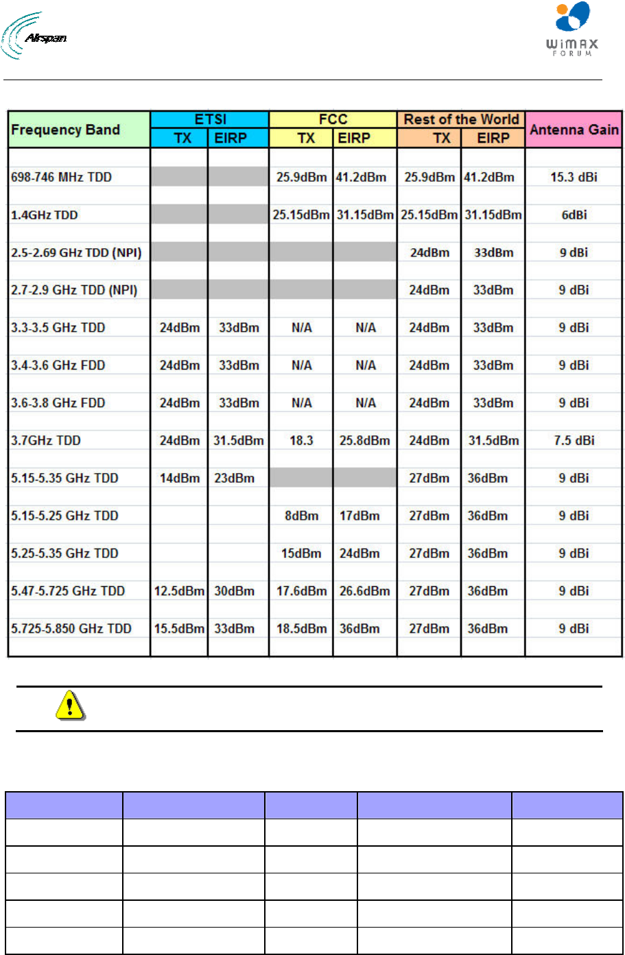
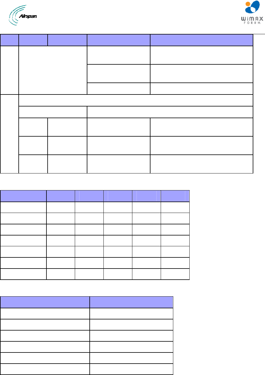
Maximum Output TX Power
Figure 1 - EasyST Maximum Output TX Power
Caution: Do not set maximum output TX power higher than local regulations.
700MHz External Antennas
Table 1 - 700MHz External Antenna Types
Type Frequency range Gain Manufacturer Model number
V-Pol MCX 698-746 MHz 7.5 dBi Mars Antennas MA-WA70-AS8
Flat panel 698-746 MHz 10.5 dBi Mti Wireless Edge Ltd. MT-223003/N
Sector 698-746 MHz 12 ± 0.5 dBi Mti Wireless Edge Ltd. MT-223002/NV
Sector 698-746 MHz 13.5 dBi Mti Wireless Edge Ltd. MT-223006/NV
Yagi directional 698 - 746 MHz 15.3 dBi Trival antene AD-40/722-14
EasyST Hardware Installation User Guide
Page 11 Commercial in Confidence UWB-D00128 Rev K
1 About this Guide
This section discusses the purpose, intended audience, conventions, referenced documentation
and organization for this document.
1.1 Purpose
This guide provides step-by-step instructions for setting up and installing the EasyST customer
premise equipment (CPE) is part of Airspan's WiMAX family of WiMAX-based products. EasyST
also has a multimode model (EasyST-2) based on the Rosedale chipset which supports both TDD
and FDD.
Note: EasyST-2 is presently available for frequencies, 3.4-3.6 and 3.6-3.8
only.
Note: For more information on the EasyST-2 contact your supplier.
The purpose of this User Guide is to provide step-by-step instructions for setting up and installing
the EasyST. These procedures include:
¾ System Overview
¾ Installation Prerequisites
¾ Physical description
¾ Cabling
¾ Mounting
¾ Connecting
1.2 Intended Audience
This guide is intended for the technician who is qualified and authorized to install the EasyST.
1.3 Conventions
Icon Description
Checkpoint: Marks a point in the workflow where there may be an exit or
branch to some other procedure. At each Checkpoint the reason for an
exit or branch is given along with specific directions to locate the entry
point in the other procedure.
Reference: Gives a resource in the workflow that may be needed to
complete a procedure along with specific directions to use the resource.
Caution: Describes a possible risk and how to lessen or avoid the risk.
Advice: Provides a recommendation based on best practice.
Note: Provides useful information.

EasyST Hardware Installation User Guide
Page 12 Commercial in Confidence UWB-D00128 Rev K
1.4 Referenced Documentation
For a detailed description of the Web-based configuration tool, refer to the WiMAX Web-based
Management for Subscriber Stations User Guide.
EasyST Hardware Installation User Guide
Page 13 Commercial in Confidence UWB-D00128 Rev K
2 System Overview
EasyST is a revolutionary, self-install, indoor WiMAX customer premises equipment (CPE). The
EasyST is designed to work with WiMAX compliant base stations including the base station
products in the AS.MAX family. The EasyST, which uses Intel Corporation’s Pro/Wireless 5116
broadband interface, connects IP-enabled devices directly to WiMAX networks and can be
installed indoors by end users within minutes without the need for costly professional installations
by an operator. EasyST is designed for the residential and small enterprise markets, providing
high-speed broadband Internet access and a Fast Ethernet connection to the subscriber's local
area network (LAN).
EasyST models support IP services at speeds of up to 37 Mbit/s over-the-air gross rates over
channel bandwidths of up to 10 MHz in both uplink and downlink. EasyST is available in
numerous ETSI frequency bands, operating in FDD and TDD modes in numerous channels, see:
EasyST Frequency Ranges and EasyST-2 Frequency Ranges.
EasyST is also available in a multi-mode model (EasyST-2) based on the Rosedale chipset which
supports both TDD and FDD.
Note: EasyST-2 is presently available for frequencies, 3.4–3.6 and 3.6–3.8
only.
EasyST uses the OFDM signaling format, providing non line-of-sight (NLOS) performance.
EasyST utilizes QAM, QPSK, and BPSK modulation technologies by modulating transmitted
signals and demodulating the received signals where the original digital message can be
recovered. The use of adaptive modulation allows EasyST to optimize throughput, yielding higher
throughputs while also covering long distances.
EasyST is typically deployed with a clip-on antenna, which is attached directly to the EasyST's top
panel. However, for deployments in rigorous terrains, the EasyST can be attached using an RF
cable to an external window-mount antenna to provide strong radio coverage.
The EasyST's compact design allows it to be deployed alongside the end-user's PC by simply
placing it on a desktop (or mounting it to a wall when using an external antenna. Easy-to-read
radio signal strength LED indicators on the EasyST's top panel enable the end user to position the
device in the optimum location, ensuring service availability and reliability, while increasing
service speed and reducing network load.
EasyST provides 10/100BaseT interface with the subscriber's LAN. In addition, the EasyST
provides an interface for adding plug-in expansion modules to provide support for features such
as:
¾ WiFi and LAN Switch (EasyWiFi module)
¾ VoIP and battery backup (EasyVoice module)
EasyST is powered by an AC/DC power adapter that is plugged into any standard electrical wall
outlet. The power adapter provides interchangeable plug prongs to suit country-specific electrical
wall sockets.
EasyST can be managed by Airspan's AS.MAX Web-based management system using standard
Web browsers, or alternatively, by an SNMP-based network management system (Netspan)
through BS intervention using standard and proprietary MIBs. In addition, external third-party
management systems such as HP OpenView can also manage the EasyST using these MIBs.

EasyST Hardware Installation User Guide
Page 14 Commercial in Confidence UWB-D00128 Rev K
2.1 EasyST Frequency Ranges
The table below lists the frequency range of EasyST models currently available. This table will
grow as more models become available.
Table 2 - EasyST Frequency Ranges
Frequency Band Channel Bandwidth
698 – 748 in MHz TDD mode ¾ 2.5 MHz
¾ 5 MHz
¾ 10 MHz
1.39 – 1.524 in GHz TDD mode ¾ 1.5 MHz
¾ 1.75 MHz
¾ 2.5 MHz
¾ 5 MHz
2.5 – 2.69 GHz in TDD mode
NPI
¾ 2.5 MHz
¾ 5 MHz
¾ 10 MHz
2.7 – 2.9 GHz in TDD mode
NPI
¾ 3 MHz
¾ 6 MHz
¾ 10 MHz
3.3 – 3.5 GHz in TDD mode ¾ 1.75 MHz
¾ 2.75 MHz
¾ 3.5 MHz
¾ 5 MHz
3.4 – 3.6 GHz in FDD mode ¾ 1.75 MHz
¾ 3.5 MHz
3.6 – 3.8 GHz in TDD mode ¾ 1.75 MHz
¾ 3.5 MHz
¾ 5 MHz
4.9 – 5.0 GHz in TDD mode ¾ 2.5 MHz
¾ 5 MHz
¾ 10 MHz
5.47 – 5.725 GHz in TDD mode ¾ 2.5 MHz
¾ 5 MHz
¾ 10 MHz
5.725 – 5.875 GHz in TDD mode ¾ 2.5 MHz
¾ 5 MHz
¾ 10 MHz
EasyST Hardware Installation User Guide
Page 15 Commercial in Confidence UWB-D00128 Rev K
5.850 – 5.950 GHz in TDD mode ¾ 2.5 MHz
¾ 5 MHz
¾ 10 MHz
2.2 Main Features
¾ World’s First "Self-Install" WiMAX Subscriber Station - fast, easy and simple installation
¾ Full Indoor Non-LOS Deployment -- 256 FFT
¾ No professional installation, simply Plug and Play -- user unpacks, plugs in and surfs
¾ Based on the latest wireless technology WiMAX IEEE 802.16 standard
¾ Based on 802.16 ProWireless 5116 Rosedale chip
¾ Compact unit occupying little space
¾ Designed to sit next to a computer on a desktop (or mounted on a wall when external
antenna used)
¾ Clip-on antenna containing four 90-degree, high-gain directional antennas providing 360
degree coverage (EasyST selects antenna with best RF reception) -- self pointing for
easy setup by untrained subscriber
¾ Provides signal strength LEDs for quick and simple alignment with provider's base station
¾ High throughput providing fast access at burst data rates of up to 37 Mbps over channel
bandwidths of up to 10 MHz
¾ Supports transparent bridging
¾ Supports multiple UL bursts per SS frame
¾ Signal information can be obtained via Web Management Performance tool
¾ Supports QoS (based on IP addresses, protocols, applications, DiffServ/TOS, 802.1p)
¾ Smart Card (SIM) option
¾ Configuration for Operator Network via integrated Smart Card (SIM) socket
¾ Stackable Style Design for adding plug-in expansion modules for the following interfaces:
• Integrated IEEE 802.11b/g WiFi access point and 4 Port LAN Switch (EasyWiFi)
allowing you to add WiFi functionality to your EasyST.
• Integrated VoIP allowing connection of 2 conventional telephones (POTS) one
Ethernet and battery backup (EasyVoice) allowing you to add VoIP functionality to
your EasyST.
¾ Low cost
Note: Contact your Airspan representative for more information on the
EasyVoice extension module or the EasyWiFi extension module.
Note: Check product specifications for latest feature content.
2.3 EasyST-2 Frequency Ranges
The table below lists the frequency range of EasyST-2, TDD/FDD Multimode models currently
available. This table will grow as more models become available.
Table 3 - EasyST-2 Frequency Ranges
EasyST Hardware Installation User Guide
Page 16 Commercial in Confidence UWB-D00128 Rev K
Frequency Band Channel Bandwidth
3.4 – 3.6 GHz in TDD/FDD 50/100 mode ¾ 1.75 MHz
¾ 2.75 MHz
¾ 3.5 MHz
¾ 5 MHz
¾ 7 MHz
¾ 10 MHz
3.6 – 3.8 GHz in TDD/FDD 50/100 mode ¾ 1.75 MHz
¾ 2.75 MHz
¾ 3.5 MHz
¾ 5 MHz
¾ 7 MHz
¾ 10 MHz
2.4 Main Features
¾ New CPE variants are equipped with Rosedale chipset enabling FDD/TDD multimode
operation, supporting 5 MHz and 7 MHz in both TDD and HFDD modes.
¾ Mobile WiMAX upgrade-able
¾ World’s First "Self-Install" WiMAX Subscriber Station - fast, easy and simple installation
¾ Full Indoor Non-LOS Deployment -- 256 FFT
¾ No professional installation, simply Plug and Play -- user unpacks, plugs in and surfs
¾ Based on the latest wireless technology WiMAX IEEE 802.16 standard
¾ Based on 802.16 ProWireless 5116 Rosedale chip
¾ Compact unit occupying little space
¾ Designed to sit next to a computer on a desktop (or mounted on a wall when external
antenna used)
¾ Clip-on antenna containing four 90-degree, high-gain directional antennas providing 360
degree coverage (EasyST selects antenna with best RF reception) -- self pointing for
easy setup by untrained subscriber
¾ Provides signal strength LEDs for quick and simple alignment with provider's base station
¾ High throughput providing fast access at burst data rates of up to 37 Mbps over channel
bandwidths of up to 10 MHz
¾ Supports transparent bridging
¾ Supports multiple UL bursts per SS frame
¾ Signal information can be obtained via Web Management Performance tool
¾ Supports QoS (based on IP addresses, protocols, applications, DiffServ/TOS, 802.1p)
¾ Smart Card (SIM) option
¾ Configuration for Operator Network via integrated Smart Card (SIM) socket
¾ Stackable Style Design for adding plug-in expansion modules for the following interfaces:
EasyST Hardware Installation User Guide
Page 17 Commercial in Confidence UWB-D00128 Rev K
• Integrated IEEE 802.11b/g WiFi access point and 4 Port LAN Switch (EasyWiFi)
which allows you to add WiFi functionality to your EasyST.
• Integrated VoIP allowing connection of 2 conventional telephones (POTS) one
Ethernet and battery backup (EasyVoice) allowing you to add VoIP functionality to
your EasyST.
¾ Low cost
Note: Contact your Airspan representative for more information on the
EasyVoice extension module or the EasyWiFi extension module.
Note: Check product specifications for latest feature content.
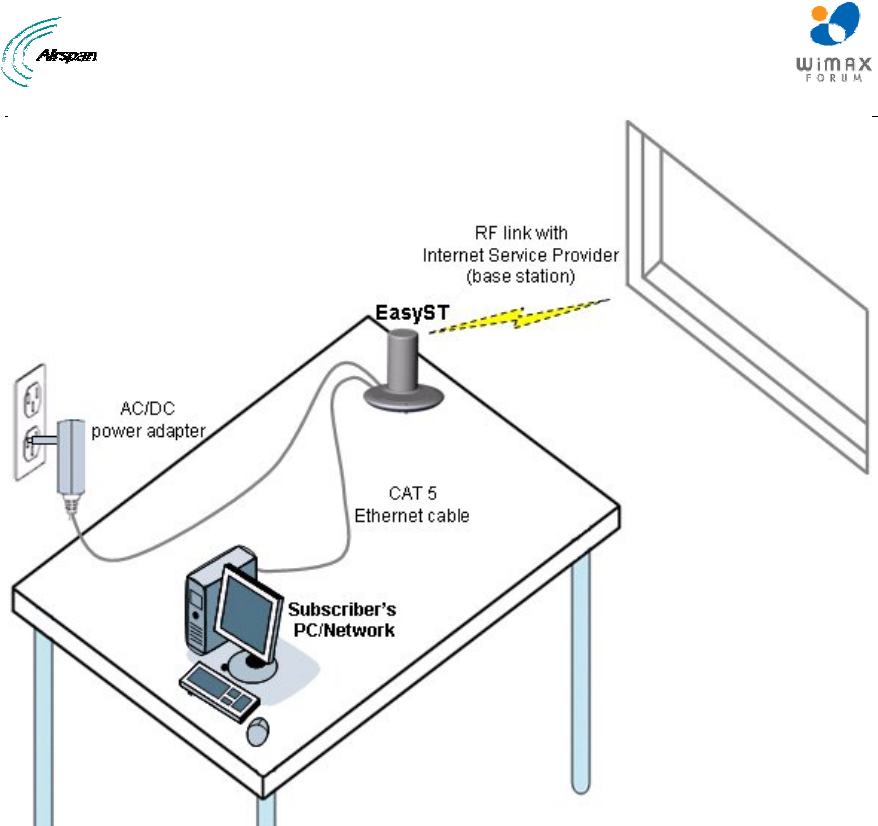
2.5 Architecture
The EasyST is a self-install indoor unit requiring no professional installation. The EasyST
architecture includes the following components:
¾ EasyST module with clip-on antenna
¾ AC/DC power adapter with interchangeable plug prongs: plugged into a standard
electrical wall outlet (110/240 VAC, 50/60 Hz), supplying the EasyST with 6 VDC power
The EasyST provides a fast and easy mounting method by allowing you to simply place it on a
desktop/table. However, if an external antenna is used, the EasyST can alternatively be mounted
on a wall.
The figure below displays the EasyST architecture:
EasyST Hardware Installation User Guide
Page 18 Commercial in Confidence UWB-D00128 Rev K
Figure 2 - EasyST architecture
2.5.1 EasyST Models
The EasyST is available in three optional deployment models:
¾ EasyST with clip-on antenna containing four high-gain, integrated flat panel, 90-degree
directional antennas, providing 360 degree coverage. EasyST selects the antenna with
best RF reception with the BS by using the 6-pin Antenna Controller.
¾ EasyST with external antenna connected by RF cable for easy window mounting.
¾ EasyST (clip on or external antenna) providing plug-in expansion modules supporting the
following interfaces:
• WiFi (EasyWiFi)
• VoIP and battery backup (EasyVoice)
• LAN switch
2.5.2 EasyST Block Diagram
The figure below displays the EasyST block diagram:

EasyST Hardware Installation User Guide
Page 19 Commercial in Confidence UWB-D00128 Rev K
Figure 3 - EasyST Block Diagram
Note: EasyST uses the antenna switch to select one of the four 90-degree
antennas of the clip-on antenna. The antenna switch is not used in
deployments in which the external window-mount antenna is implemented.
2.6 EasyST Protocol Stack
The figure below displays a block diagram of the EasyST's network architecture, designed as a
hierarchy of protocols (i.e. protocol stack) implemented in the communication network.

EasyST Hardware Installation User Guide
Page 20 Commercial in Confidence UWB-D00128 Rev K
Figure 4 - EasyST protocol stack
2.7 Theory of Operation
For basic operation, the EasyST requires no initial configuration--simply plug and play.
Configuration is automatically performed over the air by the BS. The EasyST is preconfigured by
the operator at the BS (using Netspan) with service flow parameters such as the maximum
information rate, the committed information rate, the maximum latency, and maximum jitter.
These configuration parameters are stored in Netspan's database corresponding to the EasyST's
MAC address.
Before any communication between EasyST and BS can occur, the EasyST must be positioned in
a location that provides sufficient RF reception.
To join a network, the EasyST needs to perform a few tasks. First, the "Network Entry" process
(defined in IEEE 802.16-2004) begins with the EasyST scanning for a downlink (DL) signal from
the base station, and then synchronizing to the DL channel. Thereafter the EasyST can start the
process of initial ranging, which alerts the BS to the presence of the EasyST and establishment of
management connections to obtain basic, primary and secondary management connection IDs
(CID) from the BS. After the CIDs have been obtained, the EasyST commences authorization and
key exchange. In the final stage, the EasyST registers at the base station and thereafter obtains
the IP address, time of day and the configuration file from the BS.
During Network entry, the EasyST sends the BS its MAC address. The BS via SNMP notifies
Netspan of a new CPE connection and Netspan checks the database to it contains the CPE MAC
address. The BS then accesses Netspan's database (via SNMP) and checks whether the
EasyST's MAC address appears in the database. If it locates the MAC address, the Netspan
feeds all the EasyST's configuration parameters (service flows) from the database and the BS
downloads them to the EasyST device.
EasyST Hardware Installation User Guide
Page 21 Commercial in Confidence UWB-D00128 Rev K
3 Installation Prerequisites
Before installing your EasyST, read the following sections to ensure that no EasyST items are
missing, minimum computer requirements are fulfilled, and you have the required installation
tools.
3.1 Package Contents
The EasyST kit includes the following items:
¾ EasyST module with clip-on antenna
¾ AC/DC power supply adapter
¾ CAT-5 Ethernet LAN cable (1.5 meters)
¾ Mounting kit with 2 x screws and 2 x wall anchors (implemented only when using external
antenna)
¾ Protective plastic cap cover to replace clip-on antenna (implemented only when using
external antenna)
¾ Quick Installation Guide
Note: Examine the EasyST shipping container. If you notice any damage, or
missing items as listed in the Packing List, immediately notify the carrier that
delivered the unit and contact an Airspan representative.
3.2 Minimum PC Requirements
Ensure that your computer provides an Ethernet interface such as a Network Interface Card (that
provides an RJ-45 port).
3.3 Required Tools
Typically, the EasyST requires no tools for installation, except when you want to wall mount the
unit. For wall-mounting, ensure that you have the following tools:
¾ Drill with a no. 6 twist drill bit
¾ Hammer for tapping the wall anchors into the drilled holes
¾ Pencil for marking the hole positions on the wall
¾ Philips screwdriver
EasyST Hardware Installation User Guide
Page 22 Commercial in Confidence UWB-D00128 Rev K
4 Physical Description
The EasyST's physical description is described in the following topics:
¾ Physical dimensions
¾ Ports
¾ LEDs
¾ LED Button
4.1 Physical Dimensions
The physical dimensions of the EasyST are listed in the table below:
Table 4 - EasyST physical dimensions
Parameter Value
Dimensions
(H x W x D):
¾ With clip-on antenna: 130 x 145 x 145 mm (5.12 x 5.7 x 5.7
inches)
¾ Without clip-on antenna: 30 x 145 x 145 mm (1.18 x 5.7 x 5.7
inches)
Weight: ¾ With clip-on antenna: 0.43 kg (approximate)
¾ Without clip-on antenna: 0.3 kg (approximate)
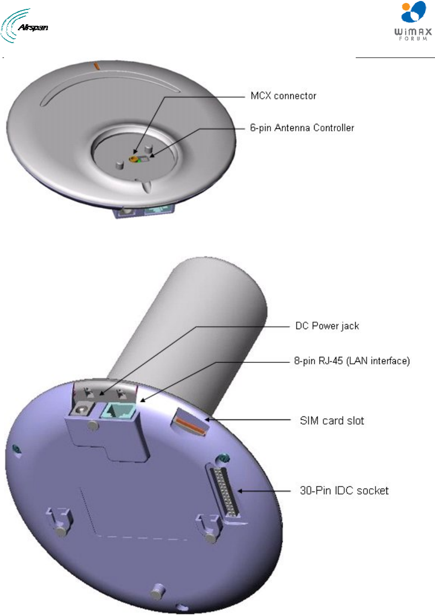
4.2 Ports
The EasyST provides various ports on its top, bottom, and side panels, as described in the table
below:
Table 5 - EasyST ports
Panel Port Interface
8-pin RJ-45 10/100BaseT Ethernet LAN
Side
DC power
jack
6 VDC power (supplied by AC/DC power adapter)
6-pin
header
Integrated Antenna Controller for attaching clip-on antenna
(determines active antenna--1 out of 4)
Top (cover
exposed)
MCX jack Clip-on antenna or window-mount external antenna
(connected by RF cable)
30-pin IDC
socket
Plug-in extension module for the following interfaces:
¾ 802.11 WiFi and LAN Switch
¾ VoIP and Battery Backup (EasyVoice)
Bottom
SIM Operator's defined parameters
The EasyST ports located on the top panel (with the clip-on antenna removed) are shown in the
figure below:
EasyST Hardware Installation User Guide
Page 23 Commercial in Confidence UWB-D00128 Rev K
Figure 5 - EasyST top panel ports
The EasyST ports located on the side and bottom panels are shown in the figure below:
Figure 6 - EasyST side and bottom panel ports
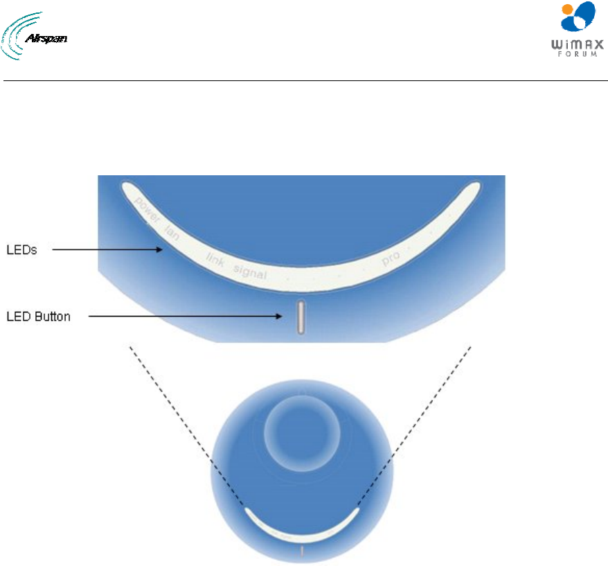
4.3 LEDs
The EasyST provides LEDs for indicating the status of various operations. These LEDs are
located on the EasyST's top panel for easy viewing, as shown in the figure below:
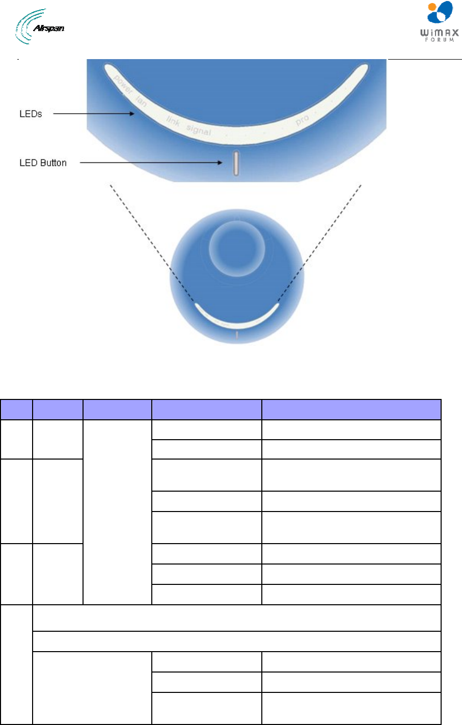
EasyST Hardware Installation User Guide
Page 24 Commercial in Confidence UWB-D00128 Rev K
Figure 7 - EasyST LEDs
The EasyST LEDs are described in the table below:
Table 6 - EasyST LEDs
LED Color Mode Status Description
On EasyST receiving power power Red
Off No power received by EasyST
On 10/100BaseT network device (e.g.
PC) correctly connected to EasyST
Flashing Active LAN link (i.e. traffic flow)
lan Green
Off No 10/100BaseT interface
connected to EasyST
On Active WiMAX link
Flashing Undergoing Network Entry
link Green
Off No WiMAX link
Customer mode
Average Signal to Noise Ratio (SNR)
All LEDs are off SNR < 5
First left-most LED is on 5 <= SNR < 9
signal
Green
Two left-most LEDs are
on
9 <= SNR < 12
EasyST Hardware Installation User Guide
Page 25 Commercial in Confidence UWB-D00128 Rev K
LED Color Mode Status Description
Three left-most LEDs
are on
12 <= SNR < 16
Four left-most LEDs are
on
16 <= SNR < 22
Five LEDs are on 22 <= SNR
PRO mode
Customer mode Off
Red Professional
Mode #1
On Modulation (See table below)
Green Professional
Mode #2
On RSSI (See table below)
signal
N/
A
Professional
Mode #3
N/
A
N/A
Table 7 - Professional Mode # 1
Modulation LED #1 LED #2 LED #3 LED #4 LED #5
BPSK_1/2 OFF ON OFF OFF OFF
QPSK_1/2 OFF OFF ON OFF OFF
QPSK_3/4 ON OFF ON OFF OFF
16QAM-1/2 OFF OFF OFF ON OFF
16QAM_3/4 ON OFF OFF ON OFF
64QAM_2/3 OFF OFF OFF OFF ON
64QAM_3/4 ON OFF OFF OFF ON
Table 8 - Professional Mode # 2 - RSSI
Average RSSI Values (dBm) 5 Signal LEDs
RSSI < (-95) All LEDs are OFF
(-95) < = RSSI< (-90) First (left) LED is ON
(-90) < = RSSI < (-85) Two first (left) LEDs are ON
(-85) < = RSSI < (-80) Three left LEDs are ON
(-80) < = RSSI < (-75) Four left LEDs are ON
(-75) < = RSSI Five LEDs are ON
4.4 LED Button
The LED button (full support pending) located below the LED lights provides the following
functionality:
¾ Toggles between LED modes: Each time you press the button, the LED mode changes:
EasyST Hardware Installation User Guide
Page 26 Commercial in Confidence UWB-D00128 Rev K
• Customer (standard mode): Signal LEDs display SNR value as described in the
table above
• Professional #1: provides technician with an indication of the modulation and FEC
used in the uplink
• Professional #2: provides technician with indication of RSSI
• Professional #3: provides technician with indication of downlink throughput (planned
for future)
¾ Resets EasyST to factory default settings: To reset to default settings, hold down the
button for 10 seconds.
Note: When any of the Professional modes are active for 30 seconds, the
mode returns automatically to the Customer mode.
EasyST Hardware Installation User Guide
Page 27 Commercial in Confidence UWB-D00128 Rev K
5 Cabling
Cabling your EasyST is fast and simple, and consists of the following:
¾ Connecting EasyST to a computer
¾ Connecting EasyST to power
¾ Verifying correct cabling
5.1 Connecting EasyST to a Computer
EasyST provides 10/100BaseT (Fast Ethernet) interface with the subscriber's network. The
connectivity is performed through the supplied Category 5 Ethernet cable consisting of 8-pin RJ-
45 connectors on either end.
The EasyST-to-computer cable setup is as follows:
¾ Cable: straight-through CAT 5 Ethernet cable
¾ Connector: 8-pin RJ-45
¾ Connector pinouts:
Table 9 – pinouts
Pin Function
1 Rx+
2 Rx-
3 Tx+
6 Tx-
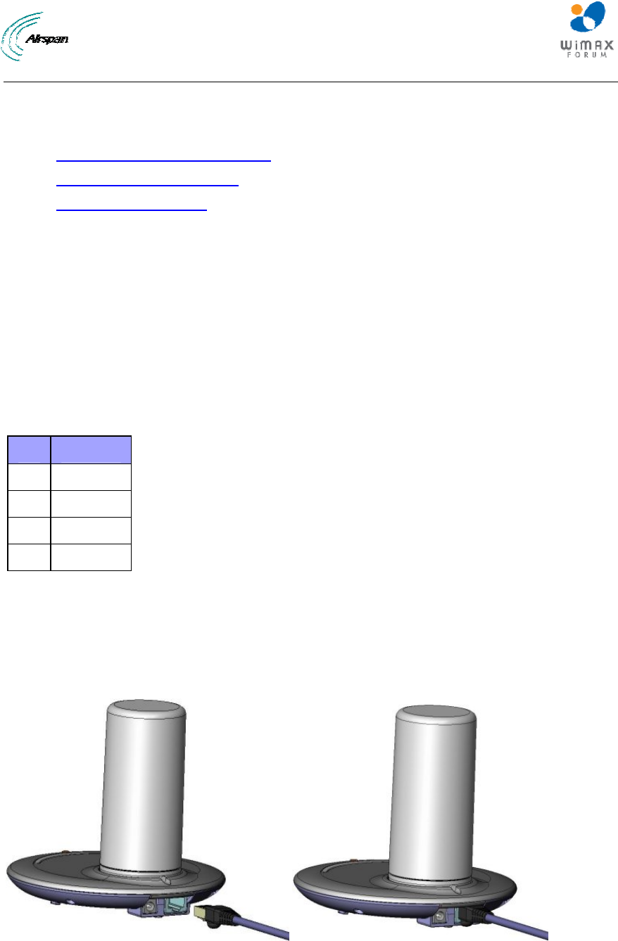
To connect EasyST to the subscriber's network:
1. Plug the supplied Category 5 Ethernet cable into the EasyST's 8-pin RJ-45 port.
2. Plug the other end of the Category 5 Ethernet cable into your computer's LAN port located at
the back of your computer.
The figure below illustrates the CAT 5 cable connection to the EasyST's RJ-45 port:
Figure 8 - cable connection
The figure below illustrates the CAT 5 cable connection to the computer's LAN port:
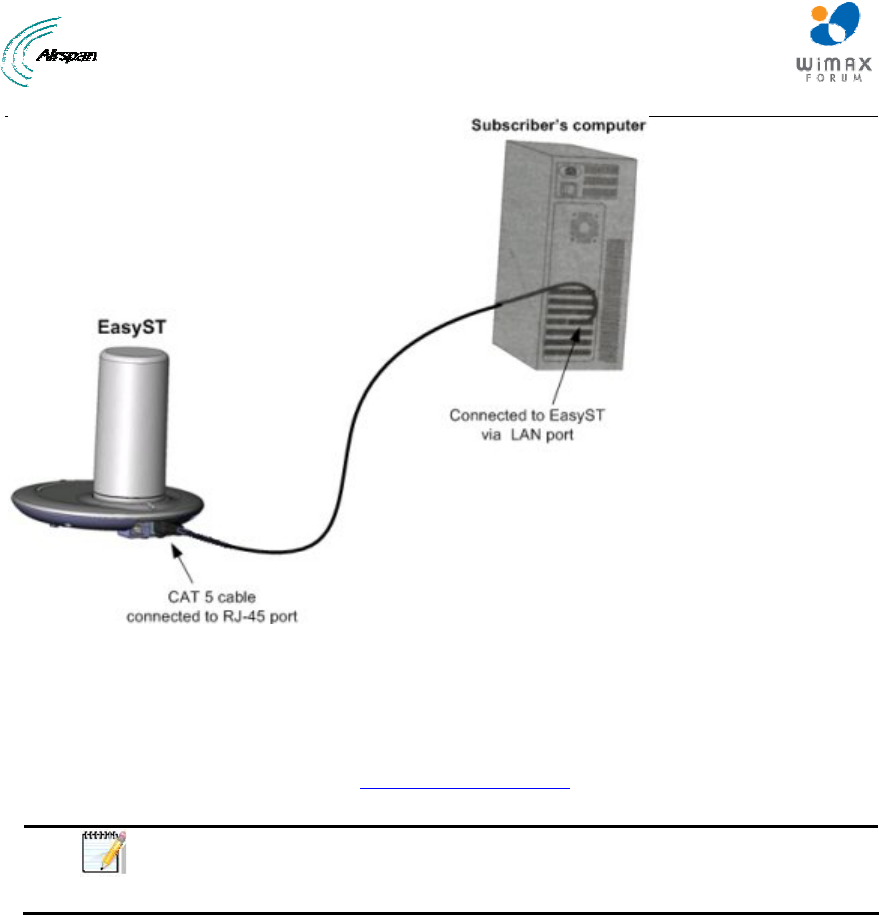
EasyST Hardware Installation User Guide
Page 28 Commercial in Confidence UWB-D00128 Rev K
Figure 9 - EasyST to PC port
5.2 Connecting EasyST to Power
EasyST is powered by an AC/DC power supply adapter which supplies the EasyST with 6 VDC (7
Watts). The AC/DC adapter is simply plugged into a standard electrical wall outlet (110/240 VAC;
50/60 Hz). The power adapter provides interchangeable prongs (e.g. American vs. European) that
can be replaced to suit country electrical standards in which the EasyST is being installed.
Note: Any AC/DC power adapter which is Class 2, LPS, and safety approved
according to national rules and that provides rated input of 100-240 V, 50/60
Hz, 0.4 A and output of 6 V, 2 A DC, may be used for powering the EasyST.
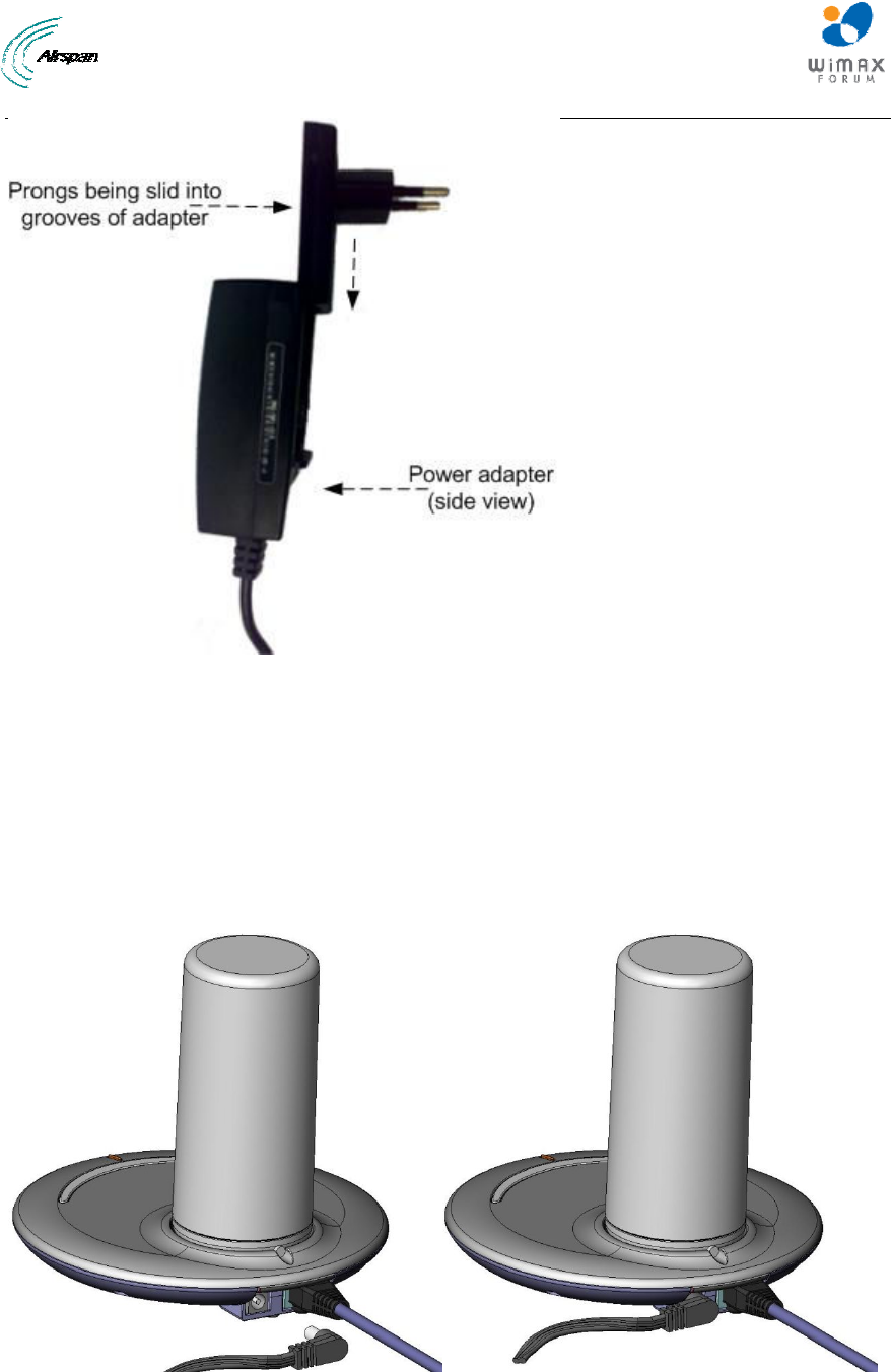
5.2.1 Changing the AC/DC Power Adapter's Prongs
The AC/DC power adapter provides interchangeable prongs to suit electrical wall outlet sockets
in the country in which the EasyST is being installed.
To change the plug prongs:
1. Remove the prongs by forcibly sliding the prongs upwards, away from the power cord.
2. Align the desired prongs with the adapter's prong groove, and then slide the prongs onto the
adapter in the orientation as shown in the figure below. Ensure that the prongs reach the end
of the prong groove.
EasyST Hardware Installation User Guide
Page 29 Commercial in Confidence UWB-D00128 Rev K
Figure 10 - change prongs
5.2.2 Connecting the Power
Once you have attached the correct plug prong to the power adapter, you can connect the power
cables.
To connect the EasyST to the power supply:
1. Before plugging the power cord into the electrical wall outlet, plug the AC/DC power
adapter's power cable (i.e. DC power jack) into the EasyST's DC power socket.
2. Plug the prongs of the AC/DC power adapter into the electrical wall outlet.
Figure 11 - cord connection
EasyST Hardware Installation User Guide
Page 30 Commercial in Confidence UWB-D00128 Rev K
5.3 Verifying Correct Cabling
Once you have connected the EasyST to the subscriber's LAN and to the power supply, you can
verify that you have cabled the EasyST correctly by checking the following EasyST LEDs:
Table 10 -verify cabling
Connection LED Color Correct Status Troubleshooting
Power power Red On If the power LED is off,
recheck the power
cabling and that power
exists at the wall socket.
LAN lan Green
On If the lan LED is off,
recheck the LAN
cabling; ensure that you
have connected it to the
correct LAN port on your
PC and that your
network connection on
your PC is enabled.
EasyST Hardware Installation User Guide
Page 31 Commercial in Confidence UWB-D00128 Rev K
6 Mounting
Caution: EasyST is an indoor unit and therefore, must be mounted only
indoors.
EasyST is a self-install indoor unit, requiring no professional technician. EasyST must be
mounted indoors in a location that provides:
¾ High quality RF reception with the Internet service provider (i.e. base station)
¾ Accessibility to power supply and LAN network with regards to cable lengths
The mounting options of the EasyST depend on the antenna configuration:
¾ EasyST with clip-on antenna: mounted horizontally on a desktop
¾ EasyST with window-mount external antenna:
• Horizontally on a desktop
• Vertically on a wall
6.1 Desktop Mounting
The EasyST can be simply placed horizontally on a desk/table (as shown in the figure below).
The EasyST radio provides integrated rubber feet (pads) on the bottom panel. These rubber feet
provide cushioning as well as insulation from static electricity.
Caution: To prevent a fire hazard caused by overheating, do not place the
EasyST on a carpeted surface where airflow is restricted.
Figure 12 - Desktop
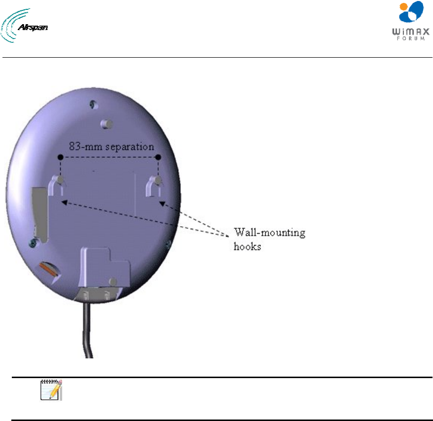
6.2 Wall Mounting
When EasyST implements the window-mount external antenna (i.e. no clip-on antenna), the
EasyST can be mounted either on a desk (i.e. desktop mounting) or a wall. For mounting to a
EasyST Hardware Installation User Guide
Page 32 Commercial in Confidence UWB-D00128 Rev K
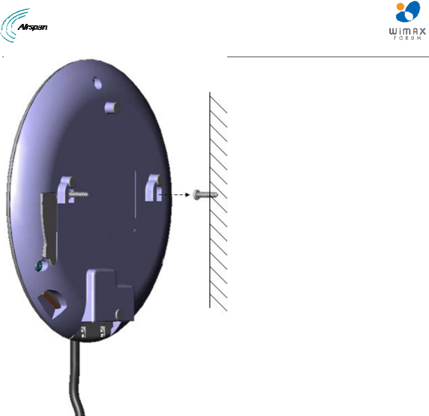
wall, the EasyST provides two mounting hooks molded into EasyST's bottom panel, as shown
below:
Figure 13 - Wall mounting
Note: Before mounting the unit, ensure that the RF cable of the window-
mount external antenna is plugged into the EasyST's MCX connector and
that the cover cap is fitted onto the EasyST, protecting the MCX connector.
To wall mount the EasyST:
1. On the wall, mark the position where you want to drill the two holes for the screws on to
which the two mounting hooks will later by guided. The distance between the two wall-
mounting hooks (from their centers) is 83 mm (3.27 inches). Ensure that the holes are
aligned and level using a spirit level.
2. Drill holes for each hole that you marked in the step above, using a no. 6 twist drill bit.
3. Insert the 6-mm wall anchors (supplied) into each of the drilled holes.
4. Drive the two 0.75-inch screws (supplied) into the wall anchors. Ensure that at least 0.08-
inch gap is exposed between the screw head and the wall anchor to allow insertion into the
EasyST mounting hooks.
5. Align the entrance to the two EasyST mounting hooks with the screws, and then pull down
the EasyST to lock the screws into the mounting hooks.
EasyST Hardware Installation User Guide
Page 33 Commercial in Confidence UWB-D00128 Rev K
Figure 14 - Mounting hooks
EasyST Hardware Installation User Guide
Page 34 Commercial in Confidence UWB-D00128 Rev K
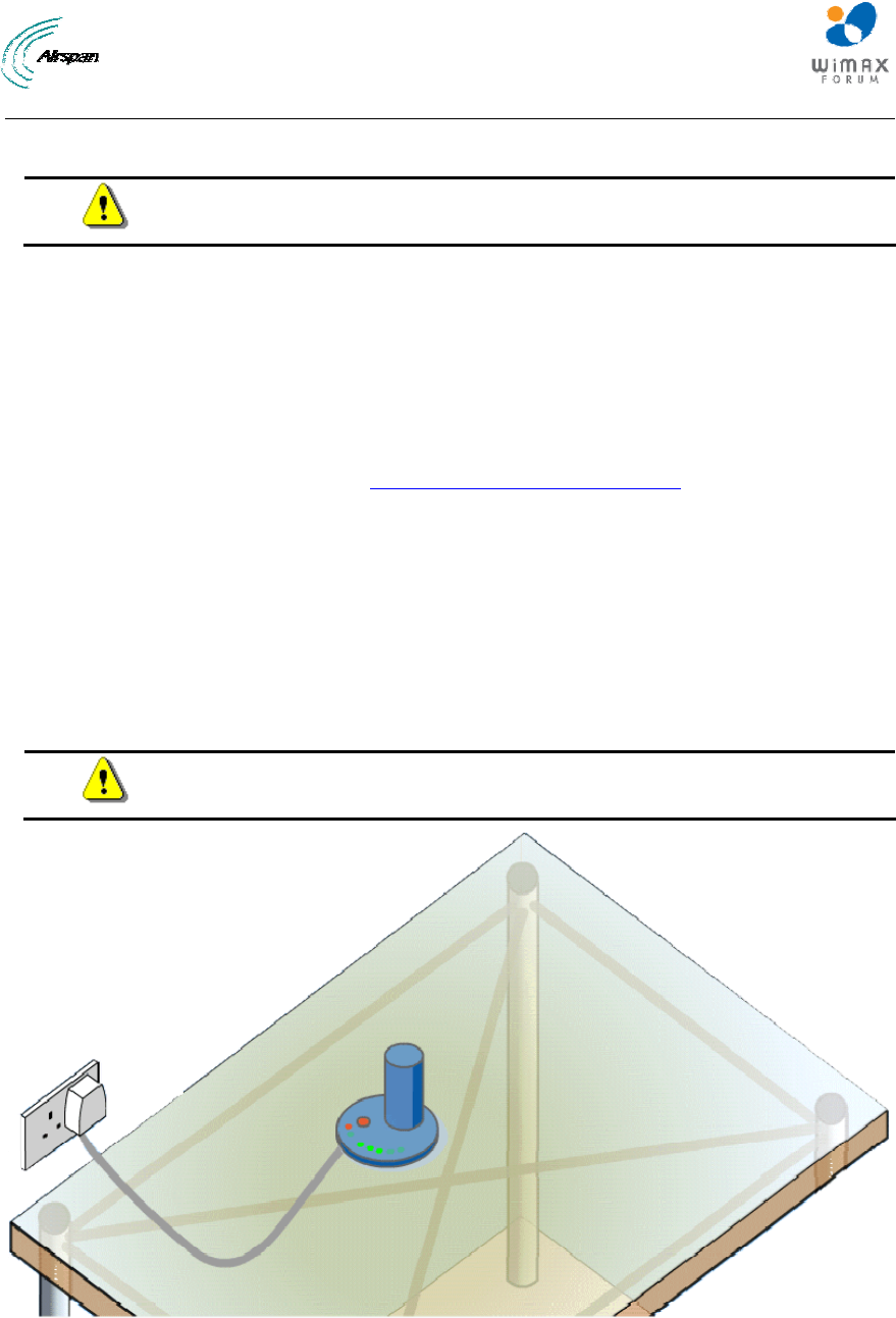
7 Optimizing RF Reception
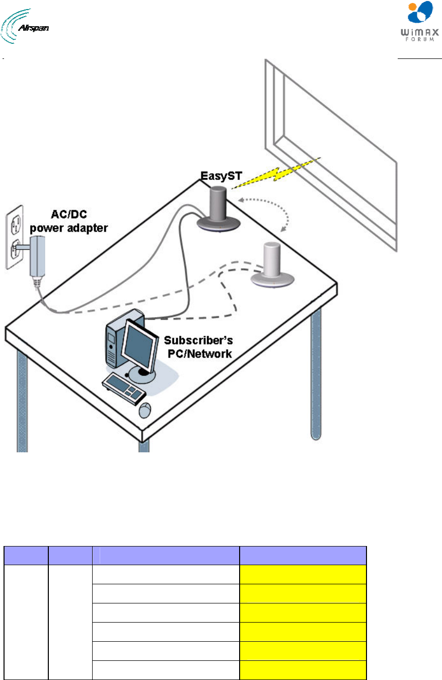
To ensure a reliable, secure, and fast connection with your Internet Service Provider (ISP), you
need to place your EasyST in a position that provides the best RF reception with the ISP (i.e.
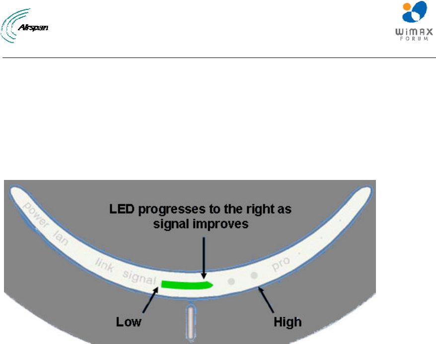
base station). To help you locate the best position, EasyST provides you with a LED indicator that
indicates the strength of the RF signal with your ISP. This LED is labeled signal and is located on
the EasyST's top panel.
As the signal strength increases, so the signal LED line progresses to the right, as illustrated
below:
Figure 15 - Signal strength LED
Therefore, for optimal reception, simply move the EasyST to the position that lights up a longer
signal LED line.
EasyST Hardware Installation User Guide
Page 35 Commercial in Confidence UWB-D00128 Rev K
Figure 16 - Positioning EasyST
The signal LED indicates the strength of the signal by measuring the signal-to-noise ratio (SNR).
SNR indicates received signal strength relative to background noise. The ratio is usually
measured in decibels (dB). Thus, the higher the SNR ratio, the better the communication.
The table below describes the EasyST signal LEDs with regards to SNR values.
Table 11 - SNR values
LED Color Status Average SNR (dBm)
All LEDs are off SNR < 5
First left-most LED is on 5 <= Avg. SNR < 9
Two left-most LEDs are on 9 <= Avg. SNR < 12
Three left-most LEDs are on 12 <= Avg. SNR < 16
Four left-most LEDs are on 16 <= Avg. SNR < 22
signal Green
Five LEDs are on 22 <= Avg. SNR
EasyST Hardware Installation User Guide
Page 36 Commercial in Confidence UWB-D00128 Rev K
8 Connecting the External Antenna
You can improve RF reception on EasyST by implementing a window-mount external antenna.
This may be necessary in the following scenarios:
¾ Subscriber's premises is located far from the base station, resulting in insufficient signal
strength for viable communication link to occur when using the clip-on antenna.
¾ Location of mounted EasyST provides insufficient signal strength due to obstacles
between the EasyST and ISP (i.e. Airspan WiMAX base station) when using the clip-on
antenna.
EasyST provides an MCX connector for attaching the window-mount, external antenna's RF cable
(approximately 1.5 meters). The external antenna can then be easily mounted in a vertical
position on a window using adhesive pads.
The connection of the external antenna to the EasyST is performed in two main steps:
¾ Attaching the antenna's RF cable to the EasyST
¾ Mounting the external antenna to a window
For a detailed list of the specifications of the external antenna, see Window-Mount Antenna
Specifications.
8.1 Attaching the Antenna RF Cable
Caution: Before connecting the external antenna, ensure that the EasyST is
NOT connected to the power source. Do not connect and disconnect
antennas while the power is on. This can cause irreversible damage to the
device.
To attach the external antenna's RF cable to the EasyST:
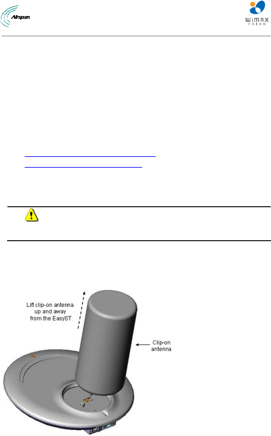
1. If you had originally ordered the EasyST with a clip-on antenna, then you need to remove it;
otherwise, skip to Step 2.
Remove the clip-on antenna by holding down on the EasyST with one hand, and then with
the other hand, lifting the clip-on antenna up and away from the EasyST.
Figure 17 - lift clip-on antenna
EasyST Hardware Installation User Guide
Page 37 Commercial in Confidence UWB-D00128 Rev K
Caution: Do not rotate the clip-on antenna until it has detached entirely from
the EasyST.
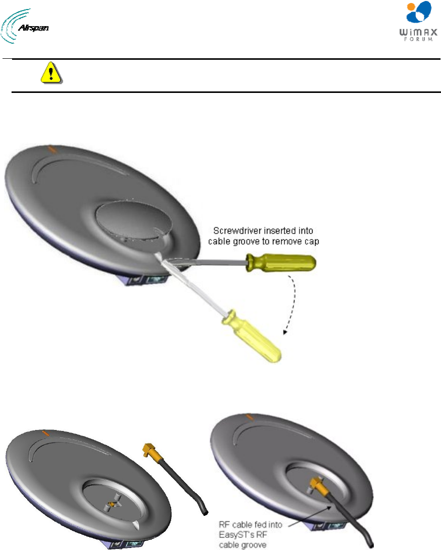
2. Remove the plastic protector cap to expose the MCX female connector. Insert a flat-head
screw driver (or any tool with a blunt, pointed edge), into the cable groove created by the cap
and the EasyST, and then gently leverage the cap's guides out of the EasyST's cover pins.
Figure 18 - remove plastic cover
3. Plug the external antenna's MCX connector into the EasyST's MCX female connector, as
shown below.
Figure 19 - connecting antenna
4. Feed the RF cable into the EasyST's RF cable groove, ensuring that the RF cable exits the
EasyST through the EasyST's RF cable groove, as shown above.
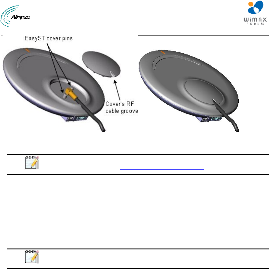
5. Protect the connectors by covering the area exposed by the removal of the clip-on antenna,
with the plastic protector cap (supplied). Attach the plastic protector cap to the exposed area,
by aligning the cap's two position cups with the EasyST's two position pins. Ensure that the
cap's RF cable groove is aligned and flush with the RF cable and EasyST's RF cable groove.
EasyST Hardware Installation User Guide
Page 38 Commercial in Confidence UWB-D00128 Rev K
Figure 20 - install plastic cap
Note: If you later decide to disconnect the external antenna and reconnect
the clip-on antenna, see Replacing the Clip-On Antenna.
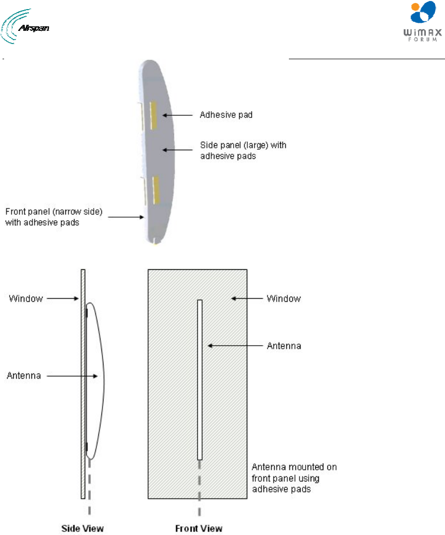
8.2 Mounting the External Antenna
The external antenna can be easily mounted in a vertical position on a window using the adhesive
pads located on the side and front panels of the antenna. The antenna can be mounted in one of
two orientations:
¾ Antenna's front panel (narrow edge) is mounted flat against the window (typical
orientation)
¾ Antenna's side panel is mounted flat against the window
Note: The external antenna must be mounted on a flat, smooth, dry, and
clean surface (i.e. window).
To window-mount the external antenna:
1. Locate the desired position on the inside of a window to where you want to mount the
antenna.
2. Remove the white tape from the adhesive pads. Do not touch the adhesive surfaces.
3. Align the antenna vertically just above the window surface to where you want to mount the
antenna, in the desired orientation (as described above).
4. Press the antenna down firmly onto the window surface so that all adhesive pads touch at
the same time. Put pressure on all the areas under which are located adhesive pads.
EasyST Hardware Installation User Guide
Page 39 Commercial in Confidence UWB-D00128 Rev K
Figure 21 - external antenna window-mount
Figure 22 - Mounting antenna on its front panel
EasyST Hardware Installation User Guide
Page 40 Commercial in Confidence UWB-D00128 Rev K
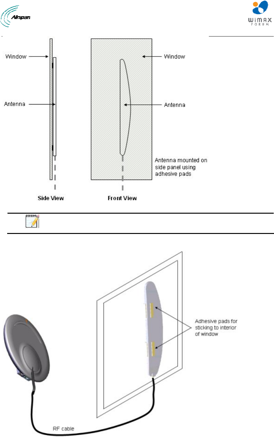
Figure 23 - Mounting antenna on its side panel
Note: When mounted on its side panel, some loss in gain may be incurred.
The figure below displays the antenna mounted on a window using the antenna's side panel.
Figure 24 - mounted antenna
EasyST Hardware Installation User Guide
Page 41 Commercial in Confidence UWB-D00128 Rev K
9 Replacing the Clip-On Antenna
The EasyST is supplied with the clip-on antenna already attached to the EasyST. However, in
cases where you may have previously removed it to connect EasyST to an external window-
mount antenna, you may want to discontinue using the external antenna and replace it with the
clip-on antenna.
Caution: Before disconnecting the external antenna and replacing the clip-on
antenna, ensure that the EasyST is not connected to the power source. Do
not connect and disconnect antennas while the power is on. This can cause
irreversible damage to the EasyST.
Note: Later EasyST models provide a screw for securing the clip-on antenna
to the EasyST.
To replace the clip-on antenna:
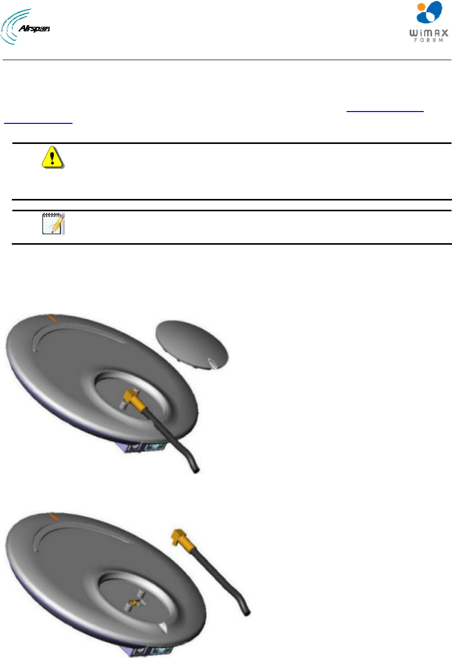
1. Remove the plastic protection cap protecting the antenna connectors, by inserting a flat-
head screw driver between the cap and the EasyST, and then gently leveraging the cap's
guides out of the EasyST's cover pins.
Figure 25 - Remove cover
2. Unplug the external antenna's MCX connector from the EasyST's MCX jack.
Figure 26 - Unplug MCX connector
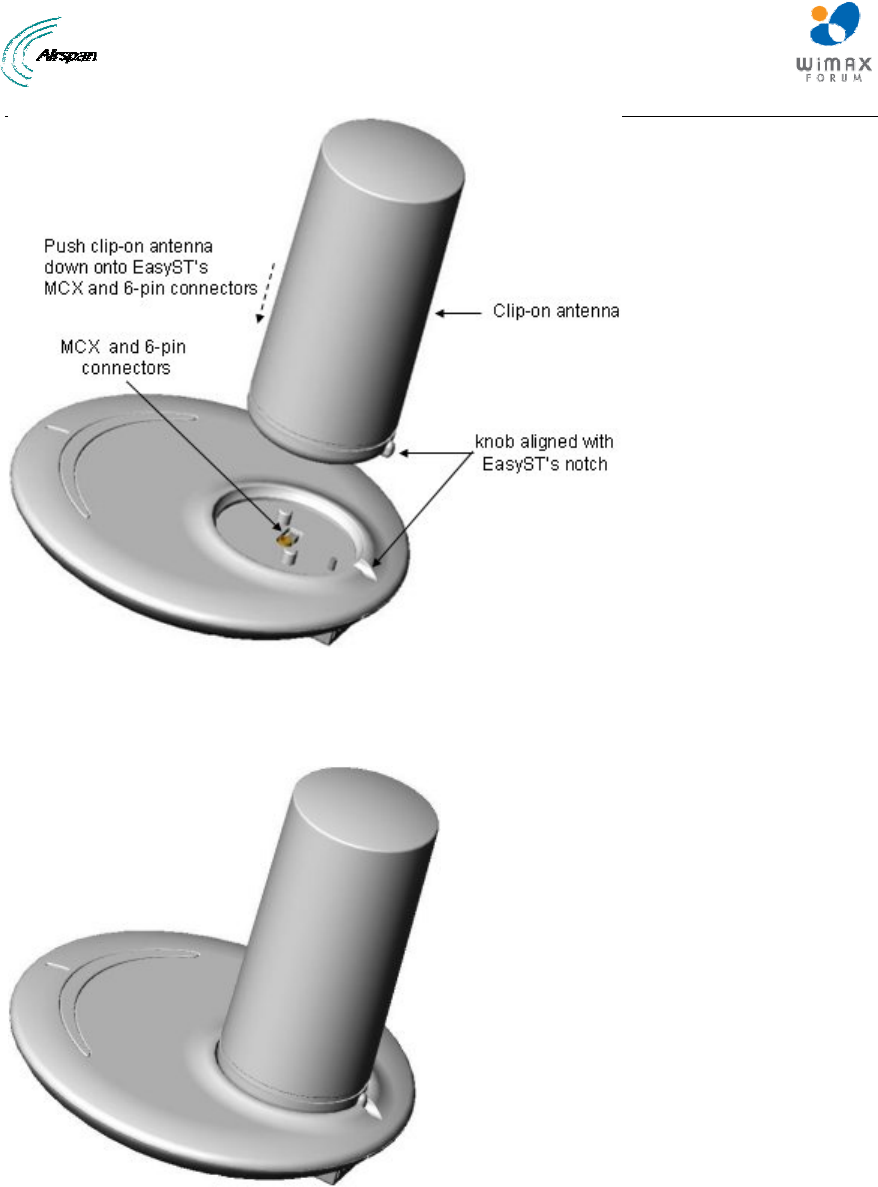
3. Align the clip-on antenna's knob with the EasyST's notch, as shown in the figure below.
EasyST Hardware Installation User Guide
Page 42 Commercial in Confidence UWB-D00128 Rev K
Figure 27 - clip-on antenna
4. Gently push the antenna down onto the EasyST so that the MCX and 6-pin connectors plug
into their respective receptacles, and that the antenna's knob sits firmly into the EasyST's
notch.
Figure 28 - antenna attached
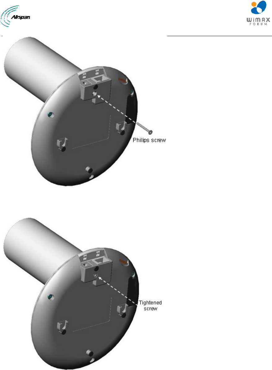
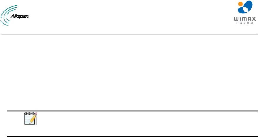
5. For customers possessing EasyST models that implement a screw mechanism for securing
the antenna to the EasyST, continue with the following steps:
a. Flip the EasyST over so that its rear panel is visible. Insert the M3 25-mm flat-head Philips
screw (supplied) into the hole that's located on the rear panel, behind the RJ-45 and DC power
connectors, as shown in the figure below.
EasyST Hardware Installation User Guide
Page 43 Commercial in Confidence UWB-D00128 Rev K
Figure 29 - insert screw
b. Using a Philips screwdriver, tighten the screw so that the antenna is firmly attached to
the EasyST.
Figure 30 - tighten screw
EasyST Hardware Installation User Guide
Page 44 Commercial in Confidence UWB-D00128 Rev K
10 EasyST Smart Card
The EasyST has an integrated Smart Card (SIM) terminal, which can utilize the optional EasyST
Smart Card (sold separately). Contact your Airspan supplier for more information.
The EasyST is fully functional with or without the EasyST Smart Card.
When the EasyST Smart Card is inserted the EasyST uses the parameters set in the card
(overriding the NVRAM parameter settings). Otherwise it uses the parameters set in the EasyST's
NVRAM. Currently the Smart Cards are available from Airspan and are configured to your specific
requirements.
Note: In the event the Smart Card is removed the EasyST continues to
function using SIM parameters, until the next reset when it utilizes the default
stored NVRAM settings.
The following defines the EasyST Smart Card stored parameters:
¾ Operator ID - defines the Operator ID by means of the BS ID and Mask in order to
enforce the CPE to be associated to a specific BS or to a group of BSs. This prevents the
CPE from connecting to other BS(s) that do not belong to this specific operator
¾ RF Channel Scanning Table - determines the channel scanning range, when there are
RF channel shifts in the table. This is performed during network entry, to find the best RF
channel with the best reception level
¾ Maximum Tx Power - defines the maximum Tx power, to meet the regulations of the
region
EasyST Hardware Installation User Guide
Page 45 Commercial in Confidence UWB-D00128 Rev K
11 Resetting EasyST to Default Settings
The EasyST allows you to apply factory default configuration settings to the EasyST. This is
performed by pressing the LED button (located below the LED lights on the top panel)
continuously for at least 10 seconds.
Figure 31 - Resetting EasyST
EasyST Hardware Installation User Guide
Page 46 Commercial in Confidence UWB-D00128 Rev K
12 Troubleshooting
Once you have connected the EasyST to the subscriber's LAN and to the power supply, you can
verify whether you have cabled the EasyST correctly by checking the EasyST LED status:
Table 12 – Troubleshooting
Connection LED Color Correct
Status Troubleshooting
Power power Red On If the power LED is off, recheck the
power cabling and that power exists at
the wall socket.
LAN lan Green
On If the lan LED is off, recheck the LAN
cabling; ensure that you have connected it
to the correct LAN port on your PC and tha
t
your network connection on your PC is
enabled.

EasyST Hardware Installation User Guide
Page 47 Commercial in Confidence UWB-D00128 Rev K
13 Appendix
13.1 Glossary of Terms
BS Base Station
BWA Broadband Wireless Access
CID Connection IDs
CPE Customer Premises Equipment (interchangeable with ST)
dB Decibel
dBm Power ratio in dB (decibel) of the measured power referenced to one milliwatt
DL Downlink
FDD Frequency Division Duplex
FEC Forward Error Correction
GHz Gigahertz
H-FDD Half-Duplex FDD
IAD Integrated Access Device
IP Internet Protocol
ISP Internet Service Provider
LAN Local-Area Network
MAC Media Access Controller. The next layer up from the PHY.
Mbit/s: Megabits per second
MHz Megahertz (one million cycles per second)
MIB Management Information Base
NLOS Non line-of-sight radio propagation path
NPI New Product Introduction
ODU Outdoor unit associated with an ST
OFDM Orthogonal Frequency Division Multiplexing
PHY The physical layer associated with the WiMAX interconnection stack
POTS Plain Old Telephone Service
QAM Quadrature Amplitude Modulation
QoS Quality of Service, which is used to specify level of data throughput
QPSK Quadrature Phase Shift Keying
RF Radio Frequency
Rx Receive
SF Service Flow

EasyST Hardware Installation User Guide
Page 48 Commercial in Confidence UWB-D00128 Rev K
SIM Subscriber Identity Module
SNMP Simple Network Management Protocol
SNR Signal-to-Noise Ratio
ST Subscriber Terminal (interchangeable with CPE or SS)
TDMA Time Division Multiple Access. Technology for delivering digital wireless service
using time-division multiplexing (TDM)
Tx Transmit
UGS Unsolicited Grant Service used to provide fixed bandwidth slots on the uplink for an
ST to transmit data at regular intervals. The bandwidth should be used by the UGS
SF, however the final decision of which SF (if any) uses the bandwidth slot is made
by the ST.
VoIP Voice over Internet Protocol
Wi-Fi Wireless Fidelity
WiMAX WiMAX is a wireless industry coalition whose members are organized to advance
IEEE 802.16 standards for broadband wireless access (BWA) networks.
13.2 Revision History
Revision Originator Date Description
01 M. Dubb 9-2005 Initial document
A M. Falik 2-2006 Warning changed to 20 cm
B M. Falik 3-006 Warning Removed
C M. Falik 4-2006 FCC Statement & warning replaced
D M. Falik 6-2006 Added SIM, additional information
E M. Falik 7-2006 Standardize document
F M. Falik 10-2006 Added tables
G M. Falik 12-2006 Frequency additions
H M. Falik 8-2007 Frequency additions + Max TX table
I M. Falik 12-2007 Additions
J M. Falik 12-2008 Template change & Frequency additions
K M. Falik 2-2009 Frequency additions + corrections
EasyST Hardware Installation User Guide
Page 49 Commercial in Confidence UWB-D00128 Rev K
13.3 Contact Information
Customer Service Help-Desk for customer service emergency
Airspan Networks have introduced the Airspan Tracker application to enable prompt and efficient
Customer Support services.
If you do not have an Airspan Tracker account, please obtain login credentials by filling-in the form in
the main page "Register New Account".
Worldwide Headquarters:
Airspan Networks Inc.
777, Yamato Road, Suite 310,
Boca Raton, FL 33431, USA
Tel: +1 561 893 8670
www.airspan.com
Feedback:
To provide feedback on this document, please send comments to the following email address:
www.airspan.com