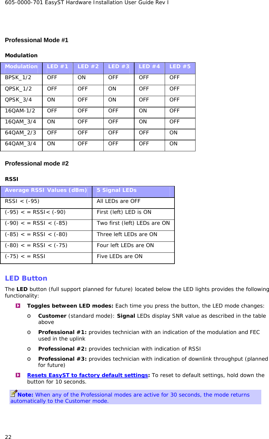
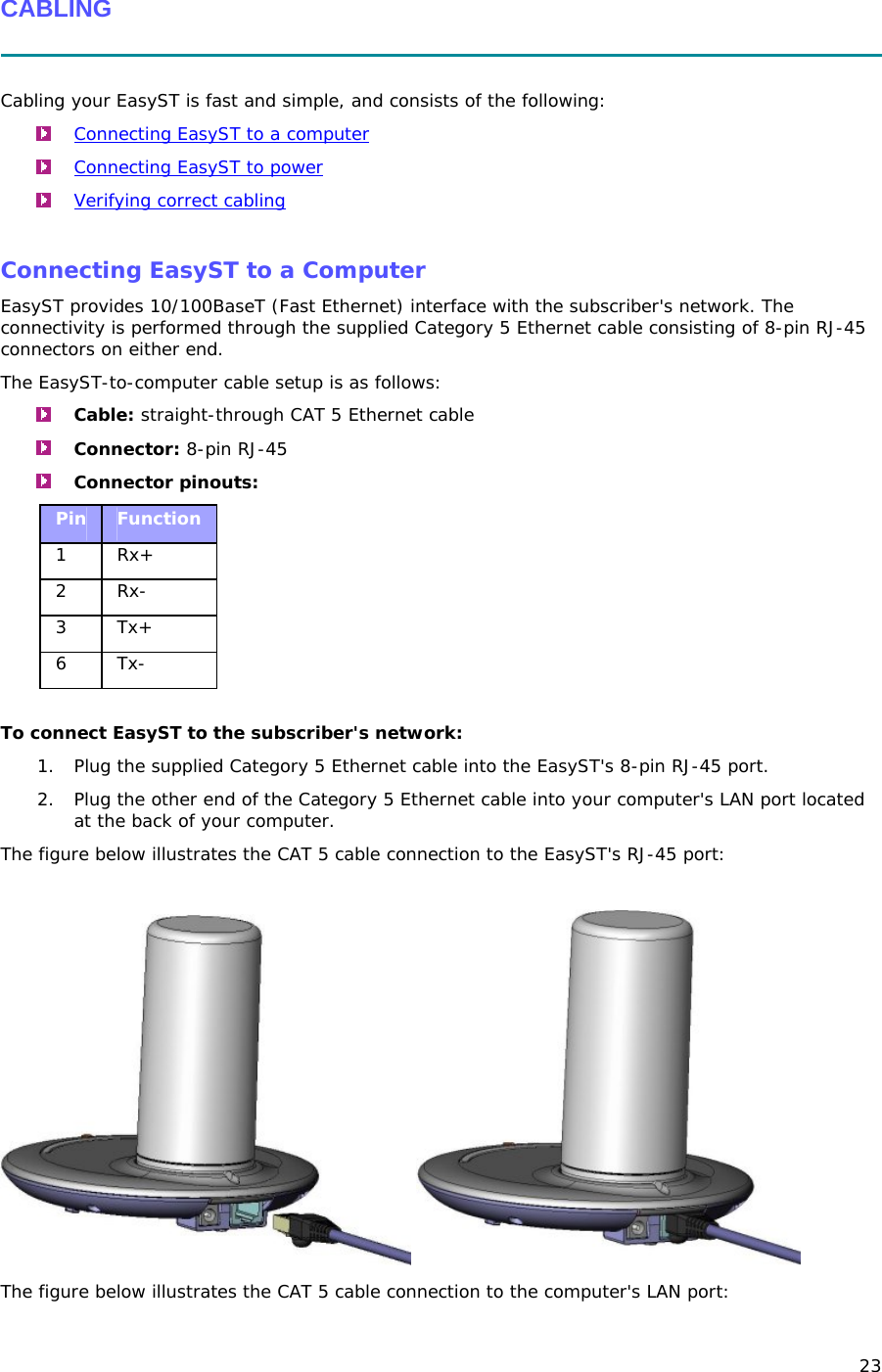
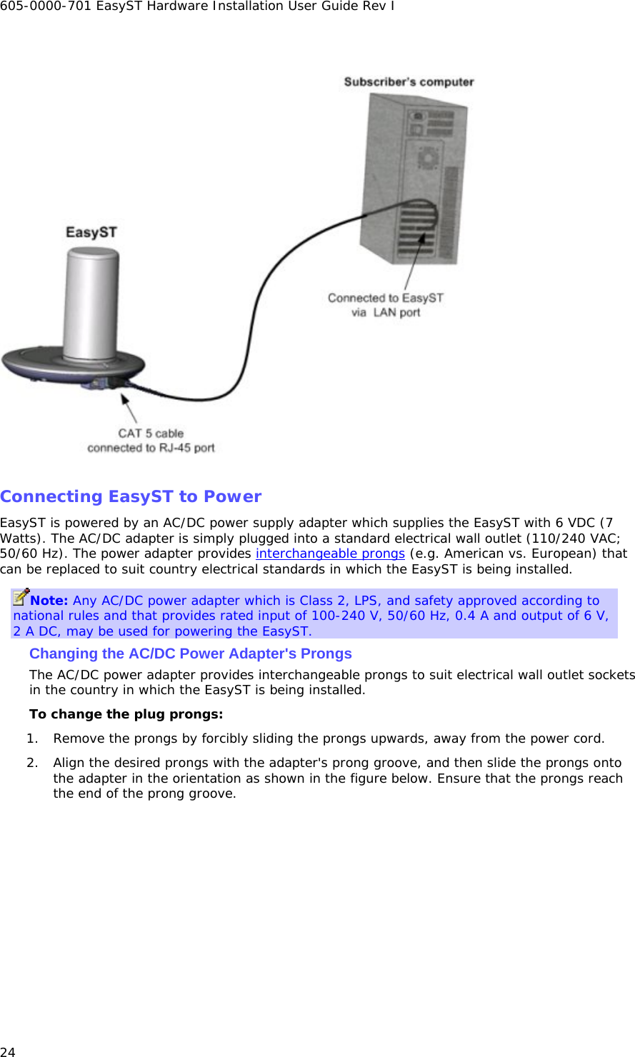
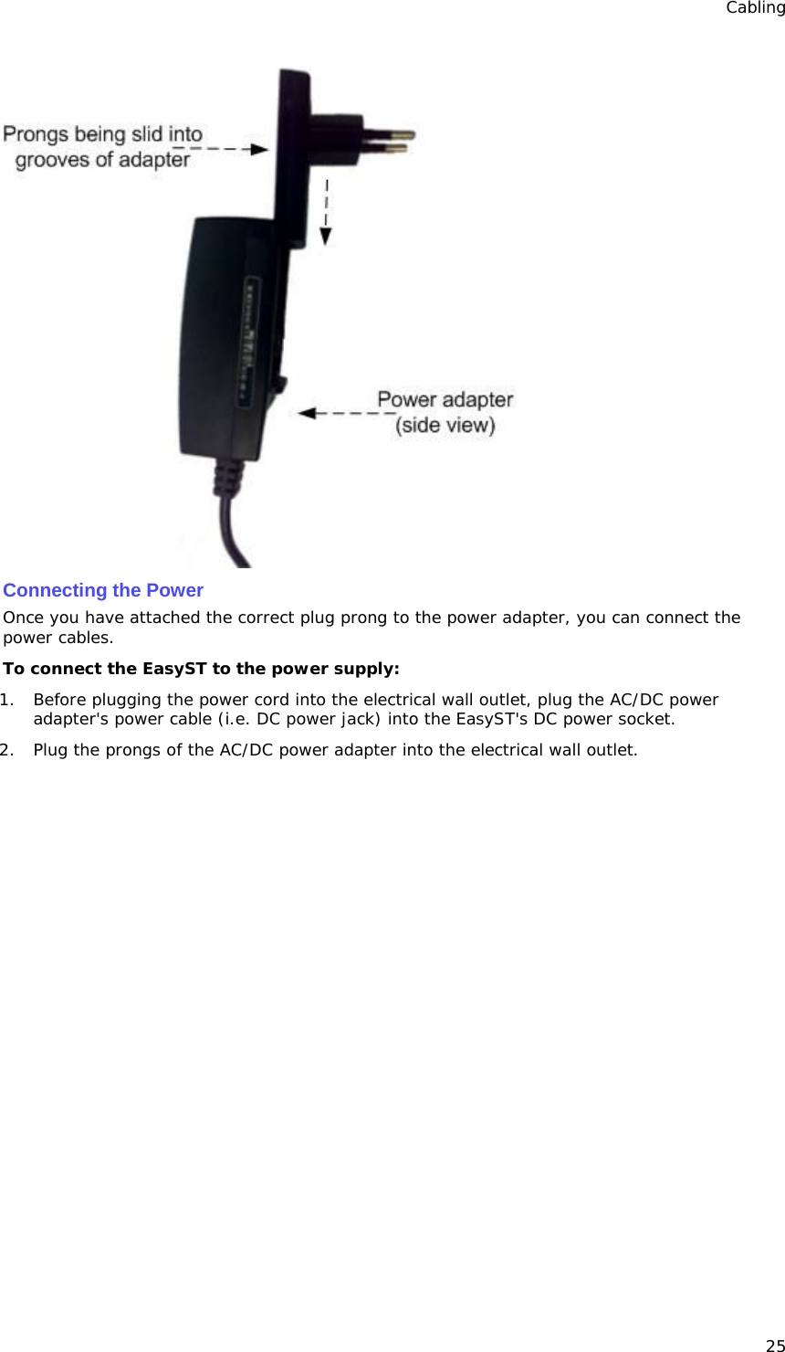
Airspan Networks ASMAX36 Terminal (subscriber) station EasyST 3.7 GHz TDD User Manual EasyST Hardware Installation User Guide

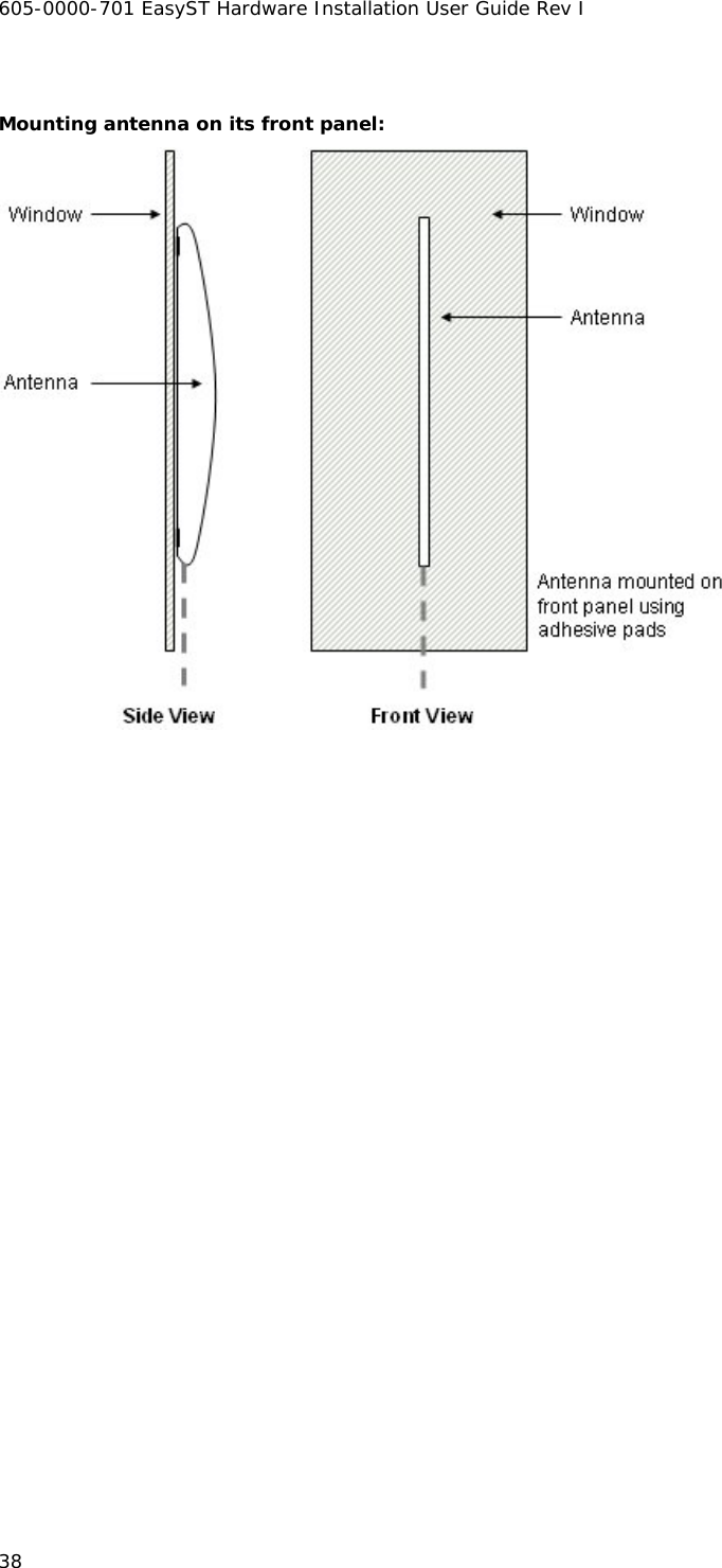
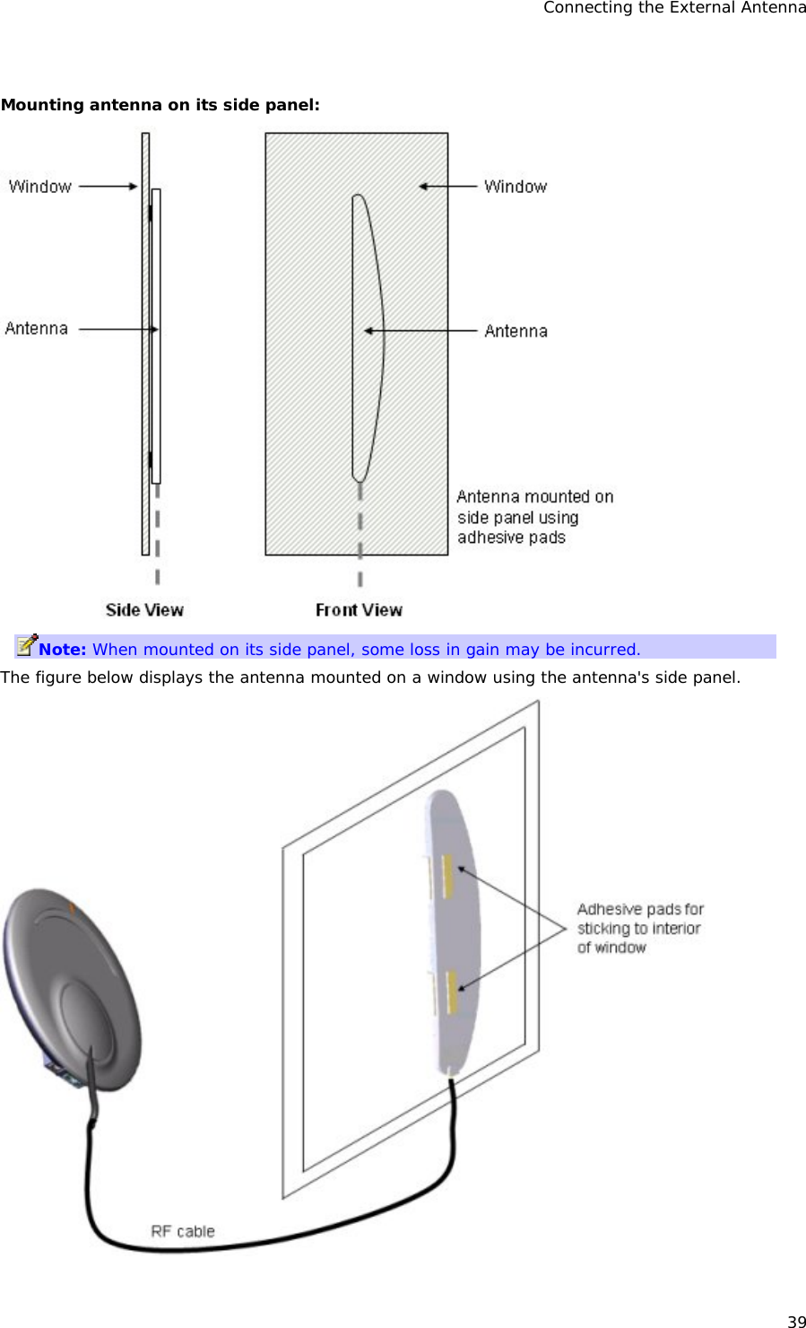
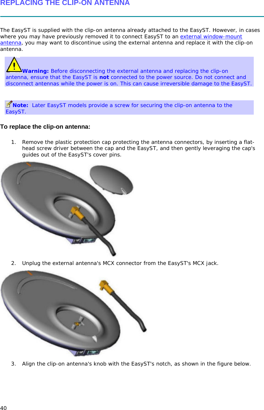
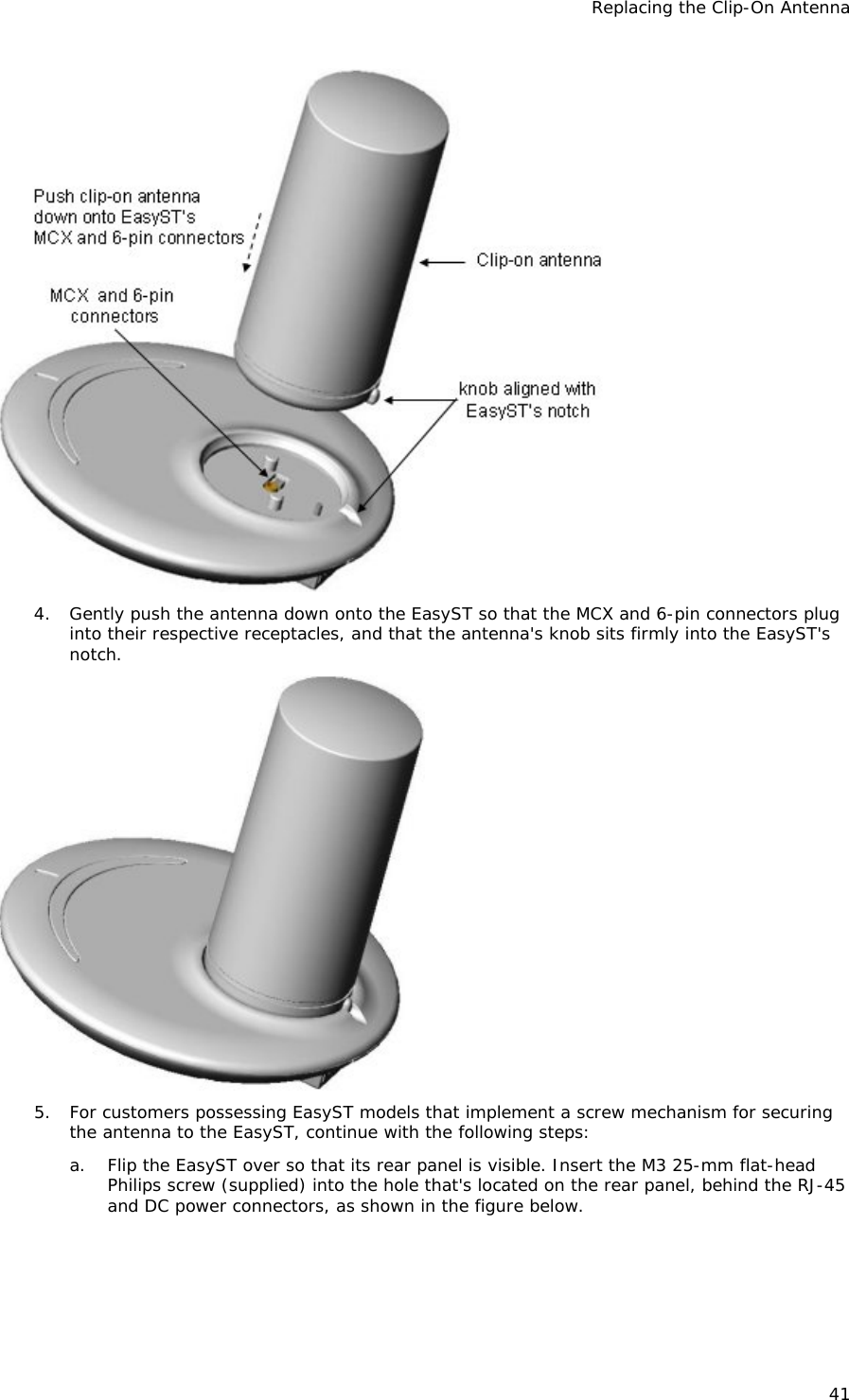
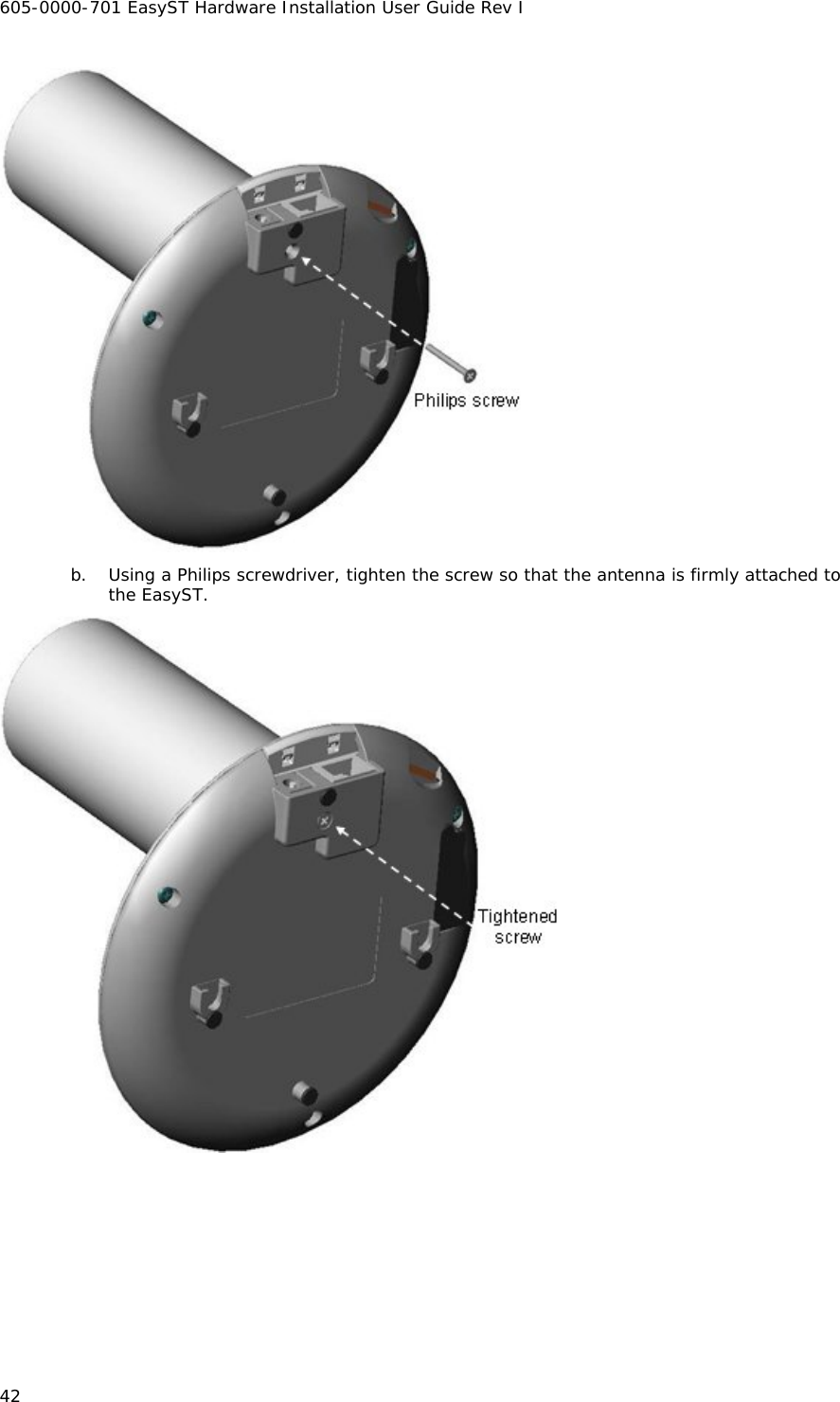
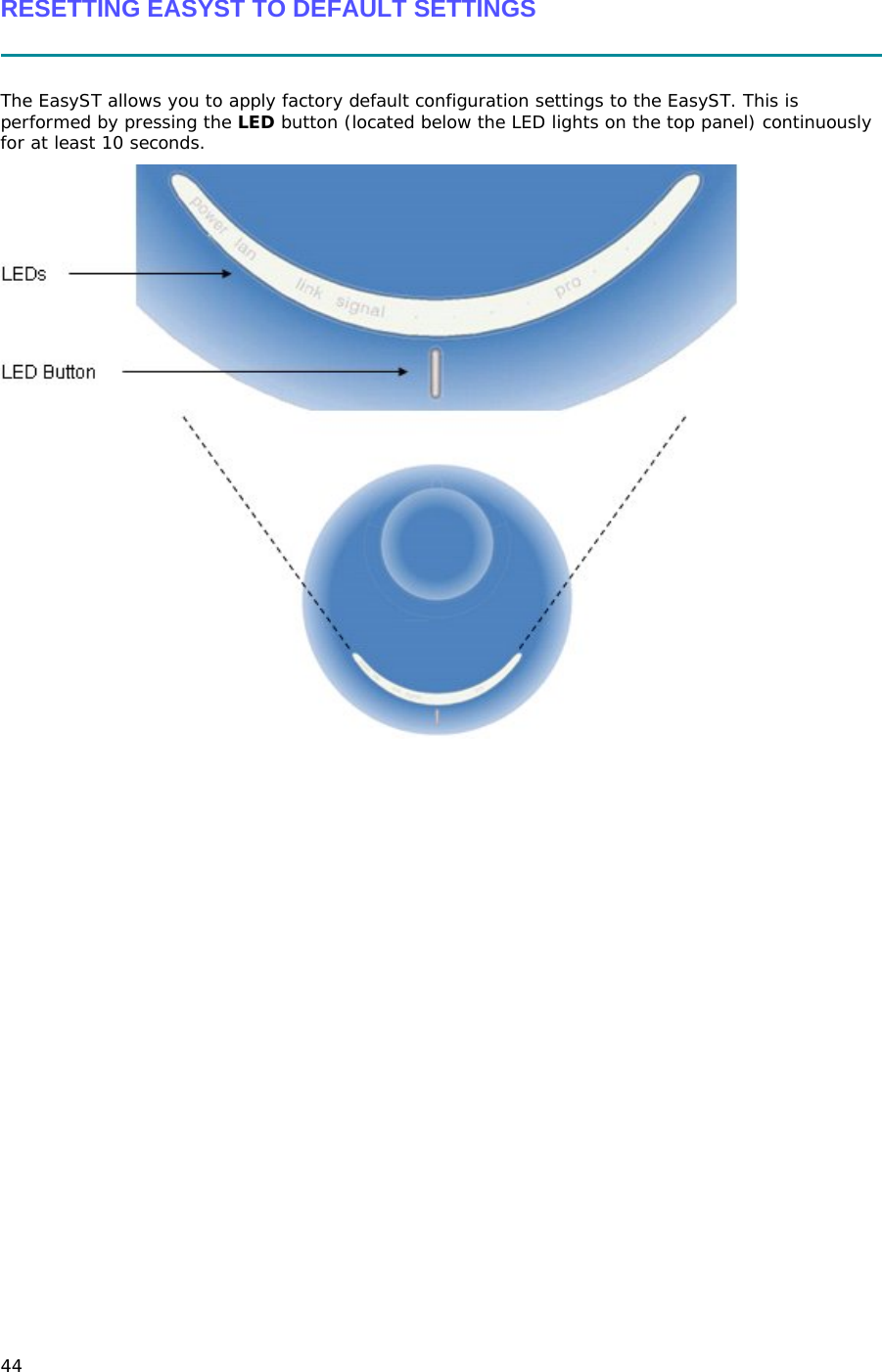
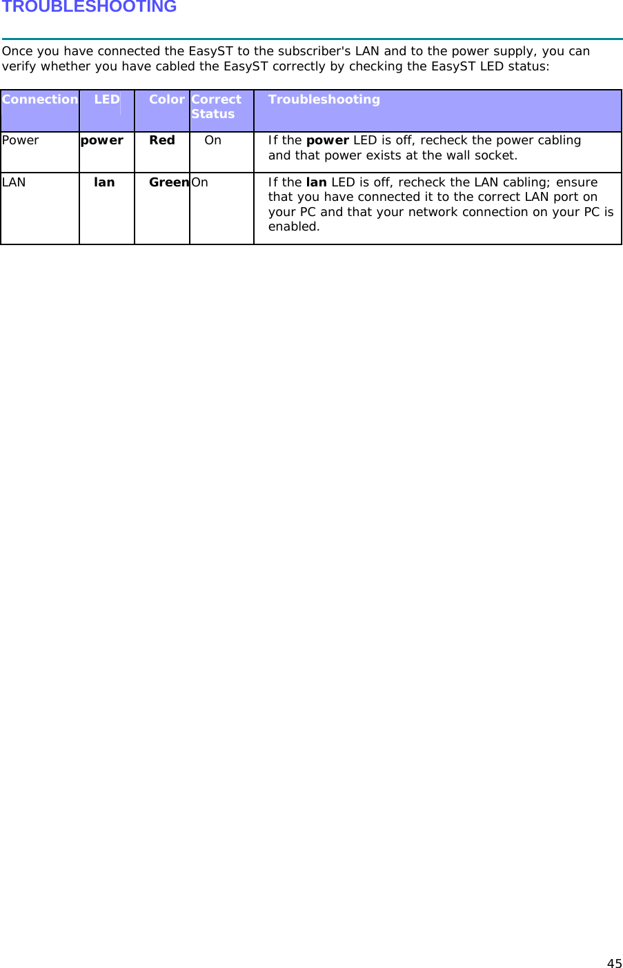
Airspan Networks Inc Terminal (subscriber) station EasyST 3.7 GHz TDD EasyST Hardware Installation User Guide

User manual

           IP-based  Broadband Wireless Access (BWA) System   605-0000-701 Rev I    EasyST Hardware Installation Guide  SR 6.5                                    The Innovation Behind Broadband Wireless Connecting the World
605-0000-701 EasyST Hardware Installation User Guide Rev I 2 Table Of Contents Introduction.......................................................................................................................4 Purpose..........................................................................................................................4 Targeted Audience ...........................................................................................................4 Referenced Documentation................................................................................................4 Conventions....................................................................................................................4 Warnings and Cautions........................................................................................................5 Human Exposure to Radio Frequencies................................................................................5 Radio Interference ...........................................................................................................5 Avoiding Radio Interference...............................................................................................5 Modifications ...................................................................................................................5 Manufacturer's Disclaimer Statement ..................................................................................5 Declaration of Conformity ....................................................................................................6 European Community, Switzerland, Norway, Iceland, and Liechtenstein ...................................6 Declaration of Conformity with Regard to the R&TTE Directive 1999/5/EC.................................6 Fcc Interference statement...................................................................................................8 Federal Communication Commission Interference Statement..................................................8 Maximum Output TX Power ...............................................................................................9 System Overview.............................................................................................................. 10 EasyST Frequency Ranges............................................................................................... 11 Main Features................................................................................................................ 11 EasyST-2 Frequency Ranges............................................................................................ 12 Main Features................................................................................................................ 12 Architecture .................................................................................................................. 13 EasyST Models............................................................................................................ 14 EasyST Block Diagram ................................................................................................. 14 EasyST Protocol Stack .................................................................................................... 15 Theory of Operation ....................................................................................................... 16 Installation Prerequisites.................................................................................................... 17 Package Contents........................................................................................................... 17 Minimum PC Requirements.............................................................................................. 17 Required Tools............................................................................................................... 17 Physical Description .......................................................................................................... 18 Physical Dimensions ....................................................................................................... 18 Ports............................................................................................................................ 18 LEDs ............................................................................................................................20 LED Button.................................................................................................................... 22 Cabling............................................................................................................................ 23 Connecting EasyST to a Computer.................................................................................... 23
3 Connecting EasyST to Power............................................................................................ 24 Changing the AC/DC Power Adapter's Prongs................................................................... 24 Connecting the Power .................................................................................................. 25 Verifying Correct Cabling................................................................................................. 27 Mounting......................................................................................................................... 28 Desktop Mounting .......................................................................................................... 28 Wall Mounting................................................................................................................ 28 Optimizing RF Reception .................................................................................................... 31 Connecting the External Antenna ........................................................................................ 34 Attaching the Antenna RF Cable ....................................................................................... 34 Mounting the External Antenna ........................................................................................ 37 Replacing the Clip-On Antenna............................................................................................ 40 EasyST Smart Card........................................................................................................... 43 Resetting EasyST to Default Settings ................................................................................... 44 Troubleshooting................................................................................................................ 45 Trademarks and Copyrights................................................................................................ 46 Contact Information.......................................................................................................... 47 Revisions......................................................................................................................... 48 Warnings......................................................................................................................... 49 1. Disclaimer................................................................................................................. 49 1.1 Safety Warnings....................................................................................................... 49 1.2 Important Warning Symbols....................................................................................... 49 1.3 Important Service Information.................................................................................... 50 1.4 UL Information......................................................................................................... 50 1.5 CE Notice ................................................................................................................ 50 1.6 European Community, Switzerland, Norway, Iceland, and Liechtenstein............................ 51 Declaration of Conformity with Regard to the R&TTE Directive 1999/5/EC............................ 51 1.7 CAUTION................................................................................................................. 52 1.8 Lightning Protection .................................................................................................. 52 Glossary.......................................................................................................................... 54 Index.............................................................................................................................. 57
605-0000-701 EasyST Hardware Installation User Guide Rev I 4 INTRODUCTION  Thank you for purchasing Airspan's EasyST wireless access device. The EasyST customer premise equipment (CPE) is part of Airspan's ASMAX family of WiMAX-based products. EasyST also has a multi-mode model (EasyST-2) based on the Rosedale chipset which supports both TDD and FDD. Note: EasyST-2 is presently available for frequencies, 3.4–3.6 and 3.6–3.8 only.  Note: For more information on the EasyST-2 contact your supplier. This section provides a preface by discussing the purpose, audience, organization, conventions, and customer support of this guide.  Purpose This guide provides a description of the EasyST as well as step-by-step instructions for installing the EasyST.  Targeted Audience This guide is intended for the end-user installing the EasyST. This device requires no professional installation.  Referenced Documentation For a detailed description of the Web-based management tool, refer to the WiMAX Web-based Management User's Guide. Conventions This guide uses the following typographical conventions:  Convention  Meaning  Example Bold    Command,  menu, icon, button, and field  Click the Next button. "To" in bold face and at the beginning of a sentence Introduces a numbered procedure   To download a SW file:  Warning that provides information that can prevent and avoid bodily or mechanical harm --  Note that provides useful information  --
5  WARNINGS AND CAUTIONS  Human Exposure to Radio Frequencies The EasyST (or the external antenna, if implemented) should be installed and operated from a minimum distance of 20 cm to your body. Radio Interference This equipment generates, uses, and can radiate radio frequency energy and, if not installed and used in accordance with the instructions, may cause harmful interference to radio communications. However, there is no guarantee that interference will not occur in a particular installation. If this equipment does cause harmful interference to radio or television reception, which can be determined by turning the equipment on and off, the user is encouraged to try correcting the interference by performing one or more of the following measures:  Reorientate or relocate the receiving antenna   Increase separation between the equipment and receiver   Connect the equipment to an outlet on a circuit different from that to which the receiver is connected   Consult the dealer or an experienced radio/TV technician for help  Avoiding Radio Interference   This transmitter must not be co-located or operating in conjunction with any antenna or transmitter.   Ensure a minimum of 1-meter separation between co-located EasySTs.  When using an external antenna, the external antenna must not be co-located or operating in conjunction with any other antenna or transmitter. Modifications Any changes and modifications to this device that are not expressly approved by Airspan Networks may void the user's authority to operate the equipment. Manufacturer's Disclaimer Statement  The information in this document is subject to change without notice and does not represent a commitment on the part of the vendor. No warranty or representation, either expressed or implied, is made with respect to the quality, accuracy or fitness for any particular purpose of this document. The manufacturer reserves the right to make changes to the content of this document and/or the products associated with it at any time without obligation to notify any person or organization of such changes. In no event will the manufacturer be liable for direct, indirect, special, incidental or consequential damages arising out of the use or inability to use this product or documentation, even if advised of the possibility of such damages. This document contains materials protected by copyright. All rights are reserved. No part of this manual may be reproduced or transmitted in any form, by any means or for any purpose without expressed written consent of its authors. Product names appearing in this document are mentioned for identification purchases only. All trademarks, product names or brand names appearing in this document are registered property of their respective owners.
605-0000-701 EasyST Hardware Installation User Guide Rev I 6 DECLARATION OF CONFORMITY  European Community, Switzerland, Norway, Iceland, and Liechtenstein  Declaration of Conformity with Regard to the R&TTE Directive 1999/5/EC  English:  This equipment is in compliance with the essential requirements and other relevant provisions of Directive 1999/5/EC.  Deutsch:  Dieses Gerät entspricht den grundlegenden Anforderungen und den weiteren entsprecheneden Vorgaben der Richtlinie 1999/5/EU.   Dansk:  Dette udstyr er i overensstemmelse med de væsentlige krav og andre relevante bestemmelser i Directiv 1999/5/EF.   Español:  Este equipo cumple con los requisitos esenciales asi como con otras disposiciones de la Directive 1999/5/EC.   Greek:  ΜΕ ΤΗΝ ΠΑΡΟΥΣΑ Airspan ∆ΗΛΩΝΕΙ ΟΤΙ Ο ΕΞΟΠΛΙΣΜΟΣ ΣΥΜΜΟΡΦΩΝΕΤΑΙ ΠΡΟΣ ΤΙΣ ΟΥΣΙΩ∆ΕΙΣ ΑΠΑΙΤΗΣΕΙΣ ΚΑΙ ΤΙΣ ΛΟΙΠΕΣ ΣΧΕΤΙΚΕΣ ∆ΙΑΤΑΞΕΙΣ ΤΗΣ Ο∆ΗΓΙΑΣ 1999/5/ΕΚ.   Français:  Cet appareil est conforme aux exigencies essentialles et aux autres dispositions pertinantes de la Directive 1999/5/EC.   Íslenska:  Þessi búnaður samrýmist lögboðnum kröfum og öðrum ákvæðum tilskipunar 1999/5/ESB.   Italiano:  Questo apparato é conforme ai requisiti essenziali ed agli altri principi sanciti dalla Direttiva 1999/5/EC.   Nederlands:  Deze apparatuur voldoet aan de belangrijkste eisen en andere voorzieningen van richtlijn 1999/5/EC.   Norsk:  Dette utstyret er i samsvar med de grunnleggende krav og andre relevante bestemmelser i EU-directiv 1999/5/EC.   Português:  Este equipamento satisfaz os requisitos essenciais e outras provisões da Directiva 1999/5/EC.   Suomalainen:  Tämä laite täyttää direktiivin 1999/5/EY oleelliset vaatimukset ja on siinä asetettujen muidenkin ehtojen mukainen.   Svenska:
7 Denna utrustning är i överensstämmelse med de väsentliga kraven och andra relevanta bestämmelser i Direktiv 1999/5/EC.   The Declaration of Conformity related to this product can be obtained from product_management@Airspan.com
605-0000-701 EasyST Hardware Installation User Guide Rev I 8  FCC INTERFERENCE STATEMENT  Federal Communication Commission Interference Statement This equipment has been tested and found to comply with the limits for a Class B digital device, pursuant to Part 15 of the FCC Rules.  These limits are designed to provide reasonable protection against harmful interference in a residential installation.  This equipment generates, uses and can radiate radio frequency energy and, if not installed and used in accordance with the instructions, may cause harmful interference to radio communications.  However, there is no guarantee that interference will not occur in a particular installation.  If this equipment does cause harmful interference to radio or television reception, which can be determined by turning the equipment off and on, the user is encouraged to try to correct the interference by one of the following measures:  Reorient or relocate the receiving antenna.  Increase the separation between the equipment and receiver.  Connect the equipment into an outlet on a circuit different from that to which the receiver is connected.  Consult the dealer or an experienced radio/TV technician for help. This device complies with Part 15 of the FCC Rules. Operation is subject to the following two conditions: (1) This device may not cause harmful interference, and (2) this device must accept any interference received, including interference that may cause undesired operation. FCC Caution: Any changes or modifications not expressly approved by the party responsible for compliance could void the user's authority to operate this equipment. IMPORTANT NOTE: FCC Radiation Exposure Statement: This equipment complies with FCC radiation exposure limits set forth for an uncontrolled environment. This equipment should be installed and operated with minimum distance 20cm between the radiator & your body. This transmitter must not be co-located or operating in conjunction with any other antenna or transmitter.
9  Maximum Output TX Power EasyST Maximum Output TX Power  Caution: Do not set maximum output TX power higher than local regulations.
10 SYSTEM OVERVIEW   EasyST is a revolutionary, self-install, indoor WiMAX customer premises equipment (CPE). The EasyST is designed to work with WiMAX compliant base stations including the base station products in the AS.MAX family. The EasyST, which uses Intel Corporation’s Pro/Wireless 5116 broadband interface, connects IP-enabled devices directly to WiMAX networks and can be installed indoors by end users within minutes without the need for costly professional installations by an operator. EasyST is designed for the residential and small enterprise markets, providing high-speed broadband Internet access and a Fast Ethernet connection to the subscriber's local area network (LAN). EasyST models support IP services at speeds of up to 37 Mbit/s over-the-air gross rates over channel bandwidths of up to 10 MHz in both uplink and downlink. EasyST is available in numerous ETSI frequency bands, operating in FDD and TDD modes in numerous channels, see: EasyST Frequency Ranges and EasyST-2 Frequency Ranges. EasyST is also available in a multi-mode model (EasyST-2) based on the Rosedale chipset which supports both TDD and FDD. Note: EasyST-2 is presently available for frequencies, 3.4–3.6 and 3.6–3.8 only. EasyST uses the OFDM signaling format, providing non line-of-sight (NLOS) performance. EasyST utilizes QAM, QPSK, and BPSK modulation technologies by modulating transmitted signals and demodulating the received signals where the original digital message can be recovered. The use of adaptive modulation allows EasyST to optimize throughput, yielding higher throughputs while also covering long distances.  EasyST is typically deployed with a clip-on antenna, which is attached directly to the EasyST's top panel. However, for deployments in rigorous terrains, the EasyST can be attached using an RF cable to an external window-mount antenna to provide strong radio coverage.  The EasyST's compact design allows it to be deployed alongside the end-user's PC by simply placing it on a desktop (or mounting it to a wall when using an external antenna. Easy-to-read radio signal strength LED indicators on the EasyST's top panel enable the end user to position the device in the optimum location, ensuring service availability and reliability, while increasing service speed and reducing network load. EasyST provides 10/100BaseT interface with the subscriber's LAN. In addition, the EasyST provides an interface for adding plug-in expansion modules to provide support for features such as:  WiFi and LAN Switch (EasyWiFi module)  VoIP and battery backup (EasyVoice module) EasyST is powered by an AC/DC power adapter that is plugged into any standard electrical wall outlet. The power adapter provides interchangeable plug prongs to suit country-specific electrical wall sockets. EasyST can be managed by Airspan's AS.MAX Web-based management system using standard Web browsers, or alternatively, by an SNMP-based network management system (Netspan) through BS intervention using standard and proprietary MIBs. In addition, external third-party management systems such as HP OpenView can also manage the EasyST using these MIBs.
System Overview 11  EasyST Frequency Ranges The table below lists the frequency range of EasyST models currently available. This table will grow as more models become available. Frequency Band  Channel Bandwidth 1.4265 – 1.524 in GHz TDD mode   1.75 MHz  3.5 MHz  5 MHz 3.3 – 3.5 GHz in TDD mode   1.75 MHz  2.75 MHz  3.5 MHz  5 MHz 3.4 – 3.6 GHz in FDD mode   1.75 MHz  3.5 MHz 3.6 – 3.8 GHz in TDD mode   1.75 MHz  3.5 MHz  5 MHz 4.9 – 5.0 GHz in TDD mode   2.5 MHz  5 MHz  10 MHz 5.47 – 5.725 GHz in TDD mode   2.5 MHz  5 MHz  10 MHz 5.725 – 5.875 GHz in TDD mode   2.5 MHz  5 MHz  10 MHz 5.850 – 5.950 GHz in TDD mode   2.5 MHz  5 MHz  10 MHz  Main Features  World’s First "Self-Install" WiMAX Subscriber Station - fast, easy and simple installation  Full Indoor Non-LOS Deployment -- 256 FFT  No professional installation, simply Plug and Play -- user unpacks, plugs in and surfs  Based on the latest wireless technology WiMAX IEEE 802.16 standard  Based on 802.16 ProWireless 5116 Rosedale chip   Compact unit occupying little space  Designed to sit next to a computer on a desktop (or mounted on a wall when external antenna used)
605-0000-701 EasyST Hardware Installation User Guide Rev I 12  Clip-on antenna containing four 90-degree, high-gain directional antennas providing 360 degree coverage (EasyST selects antenna with best RF reception) -- self pointing for easy setup by untrained subscriber  Provides signal strength LEDs for quick and simple alignment with provider's base station  High throughput providing fast access at burst data rates of up to 37 Mbps over channel bandwidths of up to 10 MHz  Supports transparent bridging  Supports multiple UL bursts per SS frame  Signal information can be obtained via Web Management Performance tool  Supports QoS (based on IP addresses, protocols, applications, DiffServ/TOS, 802.1p)  Smart Card (SIM) option  Configuration for Operator Network via integrated Smart Card (SIM) socket  Stackable Style Design for adding plug-in expansion modules for the following interfaces: o Integrated IEEE 802.11b/g WiFi access point and 4 Port LAN Switch (EasyWiFi) allowing you to add WiFi functionality to your EasyST. o Integrated VoIP allowing connection of 2 conventional telephones (POTS) one Ethernet and battery backup (EasyVoice) allowing you to add VoIP functionality to your EasyST.  Low cost Note: Contact your Airspan representative for more information on the EasyVoice extension module or the EasyWiFi extension module.  Note: Check product specifications for latest feature content. EasyST-2 Frequency Ranges The table below lists the frequency range of EasyST-2, TDD/FDD Multimode models currently available. This table will grow as more models become available. Frequency Band  Channel Bandwidth 3.4 – 3.6 GHz in TDD/FDD 50/100 mode   1.75 MHz  2.75 MHz  3.5 MHz  5 MHz  7 MHz  10 MHz 3.6 – 3.8 GHz in TDD/FDD 50/100 mode   1.75 MHz  2.75 MHz  3.5 MHz  5 MHz  7 MHz  10 MHz  Main Features
System Overview 13  New CPE variants are equipped with Rosedale chipset enabling FDD/TDD multimode operation, supporting 5 MHz and 7 MHz in both TDD and HFDD modes.  Mobile WiMAX upgrade-able  World’s First "Self-Install" WiMAX Subscriber Station - fast, easy and simple installation  Full Indoor Non-LOS Deployment -- 256 FFT  No professional installation, simply Plug and Play -- user unpacks, plugs in and surfs  Based on the latest wireless technology WiMAX IEEE 802.16 standard  Based on 802.16 ProWireless 5116 Rosedale chip   Compact unit occupying little space  Designed to sit next to a computer on a desktop (or mounted on a wall when external antenna used)  Clip-on antenna containing four 90-degree, high-gain directional antennas providing 360 degree coverage (EasyST selects antenna with best RF reception) -- self pointing for easy setup by untrained subscriber  Provides signal strength LEDs for quick and simple alignment with provider's base station  High throughput providing fast access at burst data rates of up to 37 Mbps over channel bandwidths of up to 10 MHz  Supports transparent bridging  Supports multiple UL bursts per SS frame  Signal information can be obtained via Web Management Performance tool  Supports QoS (based on IP addresses, protocols, applications, DiffServ/TOS, 802.1p)  Smart Card (SIM) option  Configuration for Operator Network via integrated Smart Card (SIM) socket  Stackable Style Design for adding plug-in expansion modules for the following interfaces: o Integrated IEEE 802.11b/g WiFi access point and 4 Port LAN Switch (EasyWiFi) allowing you to add WiFi functionality to your EasyST. o Integrated VoIP allowing connection of 2 conventional telephones (POTS) one Ethernet and battery backup (EasyVoice) allowing you to add VoIP functionality to your EasyST.  Low cost Note: Contact your Airspan representative for more information on the EasyVoice extension module or the EasyWiFi extension module.  Note: Check product specifications for latest feature content. Architecture The EasyST is a self-install indoor unit requiring no professional installation. The EasyST architecture includes the following components:  EasyST module with clip-on antenna  AC/DC power adapter with interchangeable plug prongs: plugged into a standard electrical wall outlet (110/240 VAC, 50/60 Hz), supplying the EasyST with 6 VDC power The EasyST provides a fast and easy mounting method by allowing you to simply place it on a desktop/table. However, if an external antenna is used, the EasyST can alternatively be mounted on a wall. The figure below displays the EasyST architecture:
605-0000-701 EasyST Hardware Installation User Guide Rev I 14   EasyST Models The EasyST is available in three optional deployment models:  EasyST with clip-on antenna containing four high-gain, integrated flat panel, 90-degree directional antennas, providing 360 degree coverage. EasyST selects the antenna with best RF reception with the BS by using the 6-pin Antenna Controller.  EasyST with external antenna connected by RF cable for easy window mounting.  EasyST (clip on or external antenna) providing plug-in expansion modules supporting the following interfaces: o WiFi (EasyWiFi) o VoIP and battery backup (EasyVoice) o LAN switch EasyST Block Diagram The figure below displays the EasyST block diagram:
System Overview 15  Note: EasyST uses the antenna switch to select one of the four 90-degree antennas of the clip-on antenna. The antenna switch is not used in deployments in which the external window-mount antenna is implemented. EasyST Protocol Stack The figure below displays a block diagram of the EasyST's network architecture, designed as a hierarchy of protocols (i.e. protocol stack) implemented in the communication network.
605-0000-701 EasyST Hardware Installation User Guide Rev I 16  Theory of Operation For basic operation, the EasyST requires no initial configuration--simply plug and play. Configuration is automatically performed over the air by the BS. The EasyST is preconfigured by the operator at the BS (using Netspan) with service flow parameters such as the maximum information rate, the committed information rate, the maximum latency, and maximum jitter. These configuration parameters are stored in Netspan's database corresponding to the EasyST's MAC address. Before any communication between EasyST and BS can occur, the EasyST must be positioned in a location that provides sufficient RF reception.  To join a network, the EasyST needs to perform a few tasks. First, the "Network Entry" process (defined in IEEE 802.16-2004) begins with the EasyST scanning for a downlink (DL) signal from the base station, and then synchronizing to the DL channel. Thereafter the EasyST can start the process of initial ranging, which alerts the BS to the presence of the EasyST and establishment of management connections to obtain basic, primary and secondary management connection IDs (CID) from the BS. After the CIDs have been obtained, the EasyST commences authorization and key exchange. In the final stage, the EasyST registers at the base station and thereafter obtains the IP address, time of day and the configuration file from the BS.  During Network entry, the EasyST sends the BS its MAC address. The BS via SNMP notifies Netspan of a new CPE connection and Netspan checks the database to it contains the CPE MAC address. The BS then accesses Netspan's database (via SNMP) and checks whether the EasyST's MAC address appears in the database. If it locates the MAC address, the Netspan feeds all the EasyST's configuration parameters (service flows) from the database and the BS downloads them to the EasyST device.
 17 INSTALLATION PREREQUISITES   Before installing your EasyST, read the following sections to ensure that no EasyST items are missing, minimum computer requirements are fulfilled, and you have the required installation tools.  Package Contents The EasyST kit includes the following items:  EasyST module with clip-on antenna  AC/DC power supply adapter  Category 5 Ethernet LAN cable (1.5 meters)  Mounting kit with 2 x screws and 2 x wall anchors (implemented only when using external antenna)  Protective plastic cap cover to replace clip-on antenna (implemented only when using external antenna)  Quick Installation Guide Note: Examine the EasyST shipping container. If you notice any damage, or missing items as listed in the Packing List, immediately notify the carrier that delivered the unit and contact an Airspan representative. Minimum PC Requirements Ensure that your computer provides an Ethernet interface such as a Network Interface Card (that provides an RJ-45 port). Required Tools Typically, the EasyST requires no tools for installation, except when you want to wall mount the unit. For wall-mounting, ensure that you have the following tools:  Drill with a no. 6 twist drill bit  Hammer for tapping the wall anchors into the drilled holes  Pencil for marking the hole positions on the wall  Philips screwdriver
18   PHYSICAL DESCRIPTION   The EasyST's physical description is described in the following topics:  Physical dimensions  Ports  LEDs  LED Button  Physical Dimensions The physical dimensions of the EasyST are listed in the table below: Parameter  Value Dimensions  (H x W x D):  With clip-on antenna: 130 x 145 x 145 mm (5.12 x 5.7 x 5.7 inches)  Without clip-on antenna: 30 x 145 x 145 mm (1.18 x 5.7 x 5.7 inches) Weight:   With clip-on antenna: 0.43 kg (approximate)  Without clip-on antenna: 0.3 kg (approximate)  Ports The EasyST provides various ports on its top, bottom, and side panels, as described in the table below: Panel  Port  Interface 8-pin RJ-45  10/100BaseT Ethernet LAN Side DC power jack  6 VDC power (supplied by AC/DC power adapter) 6-pin header  Integrated Antenna Controller for attaching clip-on antenna (determines active antenna--1 out of 4) Top (cover exposed) MCX jack  Clip-on antenna or window-mount external antenna (connected by RF cable) 30-pin IDC socket  Plug-in extension module for the following interfaces:   802.11 WiFi and LAN Switch  VoIP and Battery Backup (EasyVoice) Bottom SIM Operator's defined parameters  The EasyST ports located on the top panel (with the clip-on antenna removed) are shown in the figure below:
Physical Description 19  The EasyST ports located on the side and bottom panels are shown in the figure below:
605-0000-701 EasyST Hardware Installation User Guide Rev I 20  LEDs The EasyST provides LEDs for indicating the status of various operations. These LEDs are located on the EasyST's top panel for easy viewing, as shown in the figure below:
Physical Description 21  The EasyST LEDs are described in the table below: LED  Color  Mode  Status  Description On  EasyST receiving power power  Red Off  No power received by EasyST On  10/100BaseT network device (e.g. PC) correctly connected to EasyST Flashing  Active LAN link (i.e. traffic flow) lan  Green Off  No 10/100BaseT interface connected to EasyST On Active WiMAX link Flashing  Undergoing Network Entry link  Green  Off  No WiMAX link Customer mode Average Signal to Noise Ratio (SNR) All LEDs are off  SNR < 5 First left-most LED is on  5 <=  SNR < 9 Two left-most LEDs are on  9 <= SNR < 12 Three left-most LEDs are on  12 <= SNR < 16 Four left-most LEDs are on  16 <= SNR < 22 signal  Green Five LEDs are on  22 <= SNR PRO mode Customer mode  Off Red  Professional Mode #1  On Modulation (See table below) Green Professional Mode #2  On  RSSI (See table below) signalN/A Professional Mode #3  N/A  N/A
605-0000-701 EasyST Hardware Installation User Guide Rev I 22  Professional Mode #1  Modulation Modulation  LED #1  LED #2  LED #3  LED #4  LED #5 BPSK_1/2 OFF ON  OFF OFF OFF QPSK_1/2 OFF OFF ON  OFF OFF QPSK_3/4 ON OFF ON OFF OFF 16QAM-1/2 OFF OFF OFF ON  OFF 16QAM_3/4 ON OFF OFF ON OFF 64QAM_2/3 OFF OFF OFF OFF ON 64QAM_3/4 ON  OFF OFF OFF ON Professional mode #2 RSSI Average RSSI Values (dBm)  5 Signal LEDs RSSI < (-95)  All LEDs are OFF (-95) < = RSSI< (-90)  First (left) LED is ON (-90) < = RSSI < (-85)  Two first (left) LEDs are ON (-85) < = RSSI < (-80)  Three left LEDs are ON (-80) < = RSSI < (-75)  Four left LEDs are ON (-75) < = RSSI  Five LEDs are ON  LED Button The LED button (full support planned for future) located below the LED lights provides the following functionality:  Toggles between LED modes: Each time you press the button, the LED mode changes: o Customer (standard mode): Signal LEDs display SNR value as described in the table above o Professional #1: provides technician with an indication of the modulation and FEC used in the uplink o Professional #2: provides technician with indication of RSSI o Professional #3: provides technician with indication of downlink throughput (planned for future)  Resets EasyST to factory default settings: To reset to default settings, hold down the button for 10 seconds. Note: When any of the Professional modes are active for 30 seconds, the mode returns automatically to the Customer mode.
 23 CABLING   Cabling your EasyST is fast and simple, and consists of the following:  Connecting EasyST to a computer  Connecting EasyST to power  Verifying correct cabling  Connecting EasyST to a Computer EasyST provides 10/100BaseT (Fast Ethernet) interface with the subscriber's network. The connectivity is performed through the supplied Category 5 Ethernet cable consisting of 8-pin RJ-45 connectors on either end. The EasyST-to-computer cable setup is as follows:  Cable: straight-through CAT 5 Ethernet cable  Connector: 8-pin RJ-45  Connector pinouts: Pin  Function 1 Rx+ 2 Rx- 3 Tx+ 6 Tx-  To connect EasyST to the subscriber's network: 1. Plug the supplied Category 5 Ethernet cable into the EasyST's 8-pin RJ-45 port.  2. Plug the other end of the Category 5 Ethernet cable into your computer's LAN port located at the back of your computer. The figure below illustrates the CAT 5 cable connection to the EasyST's RJ-45 port:     The figure below illustrates the CAT 5 cable connection to the computer's LAN port:
605-0000-701 EasyST Hardware Installation User Guide Rev I 24    Connecting EasyST to Power EasyST is powered by an AC/DC power supply adapter which supplies the EasyST with 6 VDC (7 Watts). The AC/DC adapter is simply plugged into a standard electrical wall outlet (110/240 VAC; 50/60 Hz). The power adapter provides interchangeable prongs (e.g. American vs. European) that can be replaced to suit country electrical standards in which the EasyST is being installed. Note: Any AC/DC power adapter which is Class 2, LPS, and safety approved according to national rules and that provides rated input of 100-240 V, 50/60 Hz, 0.4 A and output of 6 V, 2 A DC, may be used for powering the EasyST. Changing the AC/DC Power Adapter's Prongs The AC/DC power adapter provides interchangeable prongs to suit electrical wall outlet sockets in the country in which the EasyST is being installed. To change the plug prongs: 1. Remove the prongs by forcibly sliding the prongs upwards, away from the power cord. 2. Align the desired prongs with the adapter's prong groove, and then slide the prongs onto the adapter in the orientation as shown in the figure below. Ensure that the prongs reach the end of the prong groove.
Cabling 25  Connecting the Power Once you have attached the correct plug prong to the power adapter, you can connect the power cables. To connect the EasyST to the power supply: 1. Before plugging the power cord into the electrical wall outlet, plug the AC/DC power adapter's power cable (i.e. DC power jack) into the EasyST's DC power socket. 2. Plug the prongs of the AC/DC power adapter into the electrical wall outlet.
605-0000-701 EasyST Hardware Installation User Guide Rev I 26
Cabling 27  Verifying Correct Cabling Once you have connected the EasyST to the subscriber's LAN and to the power supply, you can verify that you have cabled the EasyST correctly by checking the following EasyST LEDs: Connection  LED  Color  Correct Status  Troubleshooting Power  power Red  On If the power LED is off, recheck the power cabling and that power exists at the wall socket. LAN  lan Green On If the lan LED is off, recheck the LAN cabling; ensure that you have connected it to the correct LAN port on your PC and that your network connection on your PC is enabled.
28   MOUNTING   Warning:  EasyST is an indoor unit and therefore, must be mounted only indoors. EasyST is a self-install indoor unit, requiring no professional technician. EasyST must be mounted indoors in a location that provides:  High quality RF reception with the Internet service provider (i.e. base station)  Accessibility to power supply and LAN network with regards to cable lengths  The mounting options of the EasyST depend on the antenna configuration:  EasyST with clip-on antenna: mounted horizontally on a desktop   EasyST with window-mount external antenna:  o Horizontally on a desktop  o Vertically on a wall Desktop Mounting The EasyST can be simply placed horizontally on a desk/table (as shown in the figure below). The EasyST radio provides integrated rubber feet (pads) on the bottom panel. These rubber feet provide cushioning as well as insulation from static electricity.  Warning: To prevent a fire hazard caused by overheating, do not place the EasyST on a carpeted surface where airflow is restricted.  Wall Mounting When EasyST implements the window-mount external antenna (i.e. no clip-on antenna), the EasyST can be mounted either on a desk (i.e. desktop mounting) or a wall. For mounting to a wall, the EasyST provides two mounting hooks molded into EasyST's bottom panel, as shown below:
Mounting 29  Note: Before mounting the unit, ensure that the RF cable of the window-mount external antenna is plugged into the EasyST's MCX connector and that the cover cap is fitted onto the EasyST, protecting the MCX connector. To wall mount the EasyST: 1. On the wall, mark the position where you want to drill the two holes for the screws on to which the two mounting hooks will later by guided. The distance between the two wall-mounting hooks (from their centers) is 83 mm (3.27 inches). Ensure that the holes are aligned and level using a spirit level. 2. Drill holes for each hole that you marked in the step above, using a no. 6 twist drill bit. 3. Insert the 6-mm wall anchors (supplied) into each of the drilled holes. 4. Drive the two 0.75-inch screws (supplied) into the wall anchors. Ensure that at least 0.08-inch gap is exposed between the screw head and the wall anchor to allow insertion into the EasyST mounting hooks. 5. Align the entrance to the two EasyST mounting hooks with the screws, and then pull down the EasyST to lock the screws into the mounting hooks.
605-0000-701 EasyST Hardware Installation User Guide Rev I 30
 31 OPTIMIZING RF RECEPTION   To ensure a reliable, secure, and fast connection with your Internet Service Provider (ISP), you need to place your EasyST in a position that provides the best RF reception with the ISP (i.e. base station). To help you locate the best position, EasyST provides you with a LED indicator that indicates the strength of the RF signal with your ISP. This LED is labeled signal and is located on the EasyST's top panel.  As the signal strength increases, so the signal LED line progresses to the right, as illustrated below:  Therefore, for optimal reception, simply move the EasyST to the position that lights up a longer signal LED line.
605-0000-701 EasyST Hardware Installation User Guide Rev I 32
Optimizing RF Reception 33  The signal LED indicates the strength of the signal by measuring the signal-to-noise ratio (SNR). SNR indicates received signal strength relative to background noise. The ratio is usually measured in decibels (dB). Thus, the higher the SNR ratio, the better the communication. The table below describes the EasyST signal LEDs with regards to SNR values. LED  Color  Status  Average SNR (dBm) All LEDs are off  SNR < 5 First left-most LED is on  5 <= Avg. SNR < 9 Two left-most LEDs are on   9 <= Avg. SNR < 12 Three left-most LEDs are on  12 <= Avg. SNR < 16 Four left-most LEDs are on  16 <= Avg. SNR < 22 signal Green Five LEDs are on  22 <= Avg. SNR
34   CONNECTING THE EXTERNAL ANTENNA   You can improve RF reception on EasyST by implementing a window-mount external antenna. This may be necessary in the following scenarios:  Subscriber's premises is located far from the base station, resulting in insufficient signal strength for viable communication link to occur when using the clip-on antenna.  Location of mounted EasyST provides insufficient signal strength due to obstacles between the EasyST and ISP (i.e. AS.MAX base station) when using the clip-on antenna. EasyST provides an MCX connector for attaching the window-mount, external antenna's RF cable (approximately 1.5 meters). The external antenna can then be easily mounted in a vertical position on a window using adhesive pads. The connection of the external antenna to the EasyST is performed in two main steps:  Attaching the antenna's RF cable to the EasyST  Mounting the external antenna to a window  For a detailed list of the specifications of the external antenna, see Window-Mount Antenna Specifications. Attaching the Antenna RF Cable Warning: Before connecting the external antenna, ensure that the EasyST is NOT connected to the power source. Do not connect and disconnect antennas while the power is on. This can cause irreversible damage to the device.  To attach the external antenna's RF cable to the EasyST: 1. If you had originally ordered the EasyST with a clip-on antenna, then you need to remove it; otherwise, skip to Step 2. Remove the clip-on antenna by holding down on the EasyST with one hand, and then with the other hand, lifting the clip-on antenna up and away from the EasyST.
Connecting the External Antenna 35  Warning:  Do not rotate the clip-on antenna until it has detached entirely from the EasyST.  2. Remove the plastic protector cap to expose the MCX female connector. Insert a flat-head screw driver (or any tool with a blunt, pointed edge), into the cable groove created by the cap and the EasyST, and then gently leverage the cap's guides out of the EasyST's cover pins.  3. Plug the external antenna's MCX connector into the EasyST's MCX female connector, as shown below.
605-0000-701 EasyST Hardware Installation User Guide Rev I 36          4. Feed the RF cable into the EasyST's RF cable groove, ensuring that the RF cable exits the EasyST through the EasyST's RF cable groove, as shown above.  5. Protect the connectors by covering the area exposed by the removal of the clip-on antenna, with the plastic protector cap (supplied). Attach the plastic protector cap to the exposed area, by aligning the cap's two position cups with the EasyST's two position pins. Ensure that the cap's RF cable groove is aligned and flush with the RF cable and EasyST's RF cable groove.            Note: If you later decide to disconnect the external antenna and reconnect the clip-on antenna, see Replacing the Clip-On Antenna.
Connecting the External Antenna 37  Mounting the External Antenna The external antenna can be easily mounted in a vertical position on a window using the adhesive pads located on the side and front panels of the antenna. The antenna can be mounted in one of two orientations:   Antenna's front panel (narrow edge) is mounted flat against the window (typical orientation)   Antenna's side panel is mounted flat against the window  Note: The external antenna must be mounted on a flat, smooth, dry, and clean surface (i.e. window). To window-mount the external antenna: 1. Locate the desired position on the inside of a window to where you want to mount the antenna. 2. Remove the white tape from the adhesive pads. Do not touch the adhesive surfaces. 3. Align the antenna vertically just above the window surface to where you want to mount the antenna, in the desired orientation (as described above). 4. Press the antenna down firmly onto the window surface so that all adhesive pads touch at the same time. Put pressure on all the areas under which are located adhesive pads.
605-0000-701 EasyST Hardware Installation User Guide Rev I 38  Mounting antenna on its front panel:
Connecting the External Antenna 39  Mounting antenna on its side panel:  Note: When mounted on its side panel, some loss in gain may be incurred. The figure below displays the antenna mounted on a window using the antenna's side panel.
40   REPLACING THE CLIP-ON ANTENNA   The EasyST is supplied with the clip-on antenna already attached to the EasyST. However, in cases where you may have previously removed it to connect EasyST to an external window-mount antenna, you may want to discontinue using the external antenna and replace it with the clip-on antenna. Warning: Before disconnecting the external antenna and replacing the clip-on antenna, ensure that the EasyST is not connected to the power source. Do not connect and disconnect antennas while the power is on. This can cause irreversible damage to the EasyST.   Note:  Later EasyST models provide a screw for securing the clip-on antenna to the EasyST. To replace the clip-on antenna: 1. Remove the plastic protection cap protecting the antenna connectors, by inserting a flat-head screw driver between the cap and the EasyST, and then gently leveraging the cap's guides out of the EasyST's cover pins.  2. Unplug the external antenna's MCX connector from the EasyST's MCX jack.  3. Align the clip-on antenna's knob with the EasyST's notch, as shown in the figure below.
Replacing the Clip-On Antenna 41  4. Gently push the antenna down onto the EasyST so that the MCX and 6-pin connectors plug into their respective receptacles, and that the antenna's knob sits firmly into the EasyST's notch.   5. For customers possessing EasyST models that implement a screw mechanism for securing the antenna to the EasyST, continue with the following steps: a. Flip the EasyST over so that its rear panel is visible. Insert the M3 25-mm flat-head Philips screw (supplied) into the hole that's located on the rear panel, behind the RJ-45 and DC power connectors, as shown in the figure below.
605-0000-701 EasyST Hardware Installation User Guide Rev I 42  b. Using a Philips screwdriver, tighten the screw so that the antenna is firmly attached to the EasyST.
 43 EASYST SMART CARD  The EasyST has an integrated Smart Card (SIM) terminal, which can utilize the optional EasyST Smart Card (sold separately). Contact your Airspan supplier for more information. The EasyST is fully functional with or without the EasyST Smart Card.  When the EasyST Smart Card is inserted the EasyST uses the parameters set in the card (overriding the NVRAM parameter settings). Otherwise it uses the parameters set in the EasyST's NVRAM. Currently the Smart Cards are available from Airspan and are configured to your specific requirements. Note: In the event the Smart Card is removed the EasyST continues to function using SIM parameters, until the next reset when it utilizes the default stored NVRAM settings. The following defines the EasyST Smart Card stored parameters:  Operator ID - defines the Operator ID by means of the BS ID and Mask in order to enforce the CPE to be associated to a specific BS or to a group of BSs. This prevents the CPE from connecting to other BS(s) that do not belong to this specific operator  RF Channel Scanning Table - determines the channel scanning range, when there are RF channel shifts in the table. This is performed during network entry, to find the best RF channel with the best reception level  Maximum Tx Power - defines the maximum Tx power, to meet the regulations of the region
44   RESETTING EASYST TO DEFAULT SETTINGS   The EasyST allows you to apply factory default configuration settings to the EasyST. This is performed by pressing the LED button (located below the LED lights on the top panel) continuously for at least 10 seconds.
 45 TROUBLESHOOTING  Once you have connected the EasyST to the subscriber's LAN and to the power supply, you can verify whether you have cabled the EasyST correctly by checking the EasyST LED status: Connection LED  Color Correct Status  Troubleshooting Power  power Red  On If the power LED is off, recheck the power cabling and that power exists at the wall socket. LAN  lan GreenOn If the lan LED is off, recheck the LAN cabling; ensure that you have connected it to the correct LAN port on your PC and that your network connection on your PC is enabled.
46   TRADEMARKS AND COPYRIGHTS  1. ©Airspan Networks Inc 2007 2. The information in this document is proprietary to Airspan  Networks Inc. This document may not in whole or in part be copied, reproduced, or reduced to any medium without prior consent, in writing, from Airspan Networks Incorporated.  3. This manual is subject to revision. 4. All rights reserved. 5. Right of modification reserved. 6. This manual is supplied without liability for errors or omissions. 7. No part of this manual may be reproduced or used except as authorised by contract or other written permission. 8. This equipment is conditioned by the requirement that no modifications are made to the equipment unless the changes or modifications are expressly approved by  Airspan. 9. Prerequisite skills: Personnel installing, commissioning, and maintaining the Airspan products must have a basic knowledge of telephony and radio communications, and have experience in installing, commissioning and maintaining telecommunications products. Airspan provides a range of comprehensive training courses specifically aimed at providing operators/users of Airspan products with the prerequisite skills to install, commission and or maintain the product. The courses are tailored to provide the level of training required by the operator/user. 10. AS.MAX, MacroMAX, MicroMAX, HiperMAX Netspan, EasyST, EasyVoice, EasyWiFi and ProST are brands of Airspan Networks Inc.
 47 CONTACT INFORMATION  UK Office for sales and general enquiries Airspan Communications Ltd Cambridge House Oxford Road Uxbridge Middlesex UB8 1UN  Call +44 (0) 1895 467100 Fax +44 (0) 1895 467101 email sales@ airspan.com Internet: Airspan.com  Customer Service Help-Desk for customer service emergency  Airspan Communications Limited Cambridge House Oxford Road Uxbridge Middlesex UB8 1UN Airspan Networks have introduced the Airspan Tracker application to enable prompt and efficient Customer Support services. If you do not have an Airspan Tracker account, pleaseobtain login credentials by filling-in the form in the main page "Register New Account"Urgent request for Technical Supportcan be made by telephone directly to the Technical Support Helpdesk:-International:  +44 1895 467 467 Americas:       +1 561 893 8679
48   REVISIONS  Revision Level  Date  Main Changes 01 25-9-2005 Initial Document 02  20-02-2006  Warning changed to 20 cm B 28-03-006 Warning Removed C 30-04-2006 FCC Statement & warning replaced D 12-06-2006 Added SIM, additional information E 04-07-2006 Standardize document F 22-10-2006 add tables G 11-92-2006 Frequency additions H 08-2007 Frequency additions + Max TX table I 12-2007 Additions
 49 WARNINGS  1. Disclaimer Every effort has been made to ensure the accuracy of the material provided herein; however, Airspan assumes no responsibility regarding the use of the material. Additionally, Airspan makes no representations or warranties, either expressed or implied, regarding the contents of this product. Airspan Networks Inc. shall not be liable for any misuse regarding this product. Any product performance limits stated within this document are for information purposes only and should be considered as indicative. 1.1 Safety Warnings 1. Read this User Manual and follow all operating and safety instructions. 2. Keep all product information for future reference. 3. This product is supplied with a grounding power plug. Do not defeat this important safety feature. 4. Warning: High voltages exist inside the product - do not remove the lid or base: No user serviceable parts inside. 5. CAUTION: DOUBLE POLE/NEUTRAL FUSING - Always replace the fuse with the correct type and current rating. 6. Position the power cord to avoid possible damage; do not overload wall outlets. 7. Do not place this product on or near a direct heat source, and avoid placing objects on the terminal. 8. Do not operate this device near water or in a wet location. 9. Use only a damp cloth for cleaning. Do not use liquid or aerosol cleaners. Disconnect the power before cleaning. 10. Protect the terminal by disconnecting the power if not used for long periods. 11. Mount the terminal in a Telco rack on a stable horizontal surface. 12. The radio antenna units must not be located near power lines or other electrical power circuits. 13. The radio transceiver must be properly grounded to protect against power surges and accumulated static electricity. It is the user’s responsibility to install this device in accordance with the local electrical codes: correct installation procedures for grounding of the transceiver unit, mast, lead-in wire and discharge unit, location of discharge unit, size of grounding conductors and connection requirements for grounding electrodes.  14. Installation of the transceiver must be contracted to a professional installer.  15. Disconnect Device. The socket outlet shall be installed near the equipment , easily accessible and will act as the disconnect for the device. 16. When installed in the final configuration, the product must comply with the applicable Safety Standards and regulatory requirements of the country in which it is installed. If necessary, consult with the appropriate regulatory agencies and inspection authorities to ensure compliance. 1.2 Important Warning Symbols The following symbols may be encountered during installation or troubleshooting. These warning symbols mean danger. Bodily injury may result if you are not aware of the safety hazards involved in working with electrical equipment and radio transmitters. Familiarize yourself with standard safety practices before continuing.
605-0000-701 EasyST Hardware Installation User Guide Rev I 50   Electro-Magnetic Radiation  High Voltage  1.3 Important Service Information 1. Refer all repairs to qualified service personnel. Do not remove the covers or modify any part of this device, as this will void the warranty. 2. Disconnect the power to this product and return it for service if the following conditions apply: a. The terminal does not function after following the operating instructions outlined in this manual. b. Liquid has been spilled, a foreign object is inside, or the terminal has been exposed to rain. c. The product has been dropped or the housing is damaged. 3. Locate the serial number of the terminal, antenna, and transceiver and record these on your registration card for future reference. Use the space below to affix serial number stickers. Also record the MAC address, located on the back of the terminal.  1.4 UL Information - The equipment must be properly grounded according with NEC and other local safety code requirements - Reminder to all the BWA system installers: Attention to Section 820-40 of the NEC which provides guidelines for proper grounding and, in particular, specifies that the cable ground shall be connected to the grounding system of the building, as close to the point of cable entry as is practical. 1.5 CE Notice The MacroMAX  shelf carries the CE mark to demonstrate conformity with the Radio Equipment and Telecommunications Terminal Equipment and the Mutual recognition of their conformity (R&TTE) directive 1999/5/EC. WARNING: This is a class A product. In a domestic environment this product may cause radio interference in which case the user may be required to take adequate measures. Installation The transceiver and antenna equipment must be installed in compliance with regional, national, and local regulations. It is the responsibility of the system installer and/or system operator to ensure the installed system does not exceed any operational constraints identified by local regulations.  Refer to the sections in this product User Guide for detailed information about the correct installation steps to ensure power and frequency settings are set correctly before connecting the antenna. Antenna Selection Refer to the product User Guide for a list of Airspan Networks approved antennas. Antennas not listed in the User Guide are outside the scope of this Declaration. CAUTION: European Directive 1999/519/EC details basic restrictions and reference levels on human exposure to electromagnetic fields as advised by the ICNIRP. The directive states that adherence to these recommended restrictions and reference levels should provide a high level of protection as regards the established health effects that may result from exposure to such fields.
Warnings and Cautions 51 By the very nature of the system design and installation users will not find them selves within close proximity of the subscriber terminals.  Standards EN50383 and EN50385 are the applicable harmonised standards for EM fields generated by fixed wireless equipment. The Electromagnetic fields generated by the Central Terminal antenna are below the recommended safe levels at all distances greater than 65 cm from an approved Airspan antenna. The safe distance from a non-approved antenna of length D and Sector Angle δ may be calculated using the formula: Safe distance, r = 36 / (π * D * δ)  1.6 European Community, Switzerland, Norway, Iceland, and Liechtenstein  Declaration of Conformity with Regard to the R&TTE Directive 1999/5/EC   English:   This equipment is in compliance with the essential requirements and other relevant provisions of Directive 1999/5/EC.  Deutsch:   Dieses Gerät entspricht den grundlegenden Anforderungen und den weiteren entsprecheneden Vorgaben der Richtlinie 1999/5/EU.   Dansk:   Dette udstyr er i overensstemmelse med de væsentlige krav og andre relevante bestemmelser i Directiv 1999/5/EF.   Español:   Este equipo cumple con los requisitos esenciales asi como con otras disposiciones de la Directive 1999/5/EC.   Eλληνικά:   Αυτός ο εξοπλισµός συµµορφώνεται µε τις ουσιώδεις απαιτήσεις και τις λοιπές διατάξεις της Οδηγίας 1999/5/EΚ.   Français:   Cet appareil est conforme aux exigencies essentialles et aux autres dispositions pertinantes de la Directive 1999/5/EC.   Íslenska:   Þessi búnaður samrýmist lögboðnum kröfum og öðrum ákvæðum tilskipunar 1999/5/ESB.   Italiano:   Questo apparato é conforme ai requisiti essenziali ed agli altri principi sanciti dalla Direttiva 1999/5/EC.   Nederlands:   Deze apparatuur voldoet aan de belangrijkste eisen en andere voorzieningen van richtlijn 1999/5/EC.   Norsk:   Dette utstyret er i samsvar med de grunnleggende krav og andre relevante bestemmelser i EU-directiv 1999/5/EC.   Português:
605-0000-701 EasyST Hardware Installation User Guide Rev I 52  Este equipamento satisfaz os requisitos essenciais e outras provisões da Directiva 1999/5/EC.   Suomalainen:   Tämä laite täyttää direktiivin 1999/5/EY oleelliset vaatimukset ja on siinä asetettujen muidenkin ehtojen mukainen.   Svenska:   Denna utrustning är i överensstämmelse med de väsentliga kraven och andra relevanta bestämmelser i Direktiv 1999/5/EC.   The Declaration of Conformity related to this product can be obtained from product_management@Airspan.com  1.7 CAUTION  Any modifications to this device not expressly authorized by the manufacturer could void the user's authority to operate this device. Responsible party for compliance is: David Mann, Airspan Networks Inc., Cambridge House, Oxford Rd, Uxbridge, Middlesex, England, UB8 1UN. Telephone (44) 1 895 467450. 1.8 Lightning Protection WARNING: The following notes are general recommendations for the system. The wireless equipment should be installed by a qualified professional installer and must follow local and national codes for electrical grounding and safety. Failure to meet safety requirements and/or use of non-standard practices and procedures could result in personal injury and damage to equipment. A direct lightning strike may cause serious damage even if these guidelines are followed. All outdoor wireless equipment is susceptible to lightning damage from a direct hit or induced current from a near strike. Lightning protection and grounding practices in local and national electrical codes serve to minimize equipment damage, service outages, and serious injury. Reasons for lightning damage are summarized as: - Poorly grounded tower/antenna sites that can conduct high lightning strike energy into equipment. - Lack of properly installed lightning protection equipment that can cause equipment failures from lightning induced currents. A lighting protection system provides a means by which the energy may enter earth without passing through and damaging parts of a structure. A lightning protection system does not prevent lightning from striking; it provides a means for controlling it and preventing damage by providing a low resistance path for the discharge of energy to travel safely to ground. Improperly grounded connections are also a source of noise that can cause sensitive equipment to malfunction. A good tower grounding system disperses most of the surge energy from a tower strike away from the building and equipment. The remaining energy on the RF cable shield and center conductor can be directed safely to ground by using a lightning arrestor in series with the RF cable. To limit the equipment damage due to a lightning strike, the following practices are recommended for the wireless system: - Provide direct grounding from the antenna mounting bracket, the radio and antenna and the lightning arrestors to the same ground point at the base of the tower or a ground bus on the building. Use the grounding screws on the antenna bracket and the radio and antenna for terminating the ground wires.
Warnings and Cautions 53 - Install one RF lightning protector between the radio and antenna in series with the RF cable. - A lightning arrestor in series with the RF cable at the point of entry to the building. - Install a lightning arrestor in series with the IF cable at the transceiver on the tower/mast. - The AC wall outlet ground for the MacroMAX terminal must be connected to the same grounding system as the radio and antenna lightning protectors.
54   GLOSSARY B BS: Base Station BWA: Broadband Wireless Access C CID: Connection IDs CPE: Customer Premises Equipment (interchangeable with ST) D dB: Decibel dBm: Power ratio in dB (decibel) of the measured power referenced to one milliwatt DL: Downlink F FDD: Frequency Division Duplex FEC: Forward Error Correction G GHz: Gigahertz H H-FDD: Half-Duplex FDD I IAD: Integrated Access Device IP: Internet Protocol ISP: Internet Service Provider L LAN: Local-Area Network M MAC: Media Access Controller. The next layer up from the PHY. Mbit/s: Megabits per second MHz: Megahertz (one million cycles per second) MIB: Management Information Base
Glossary 55 N NLOS: Non line-of-sight radio propagation path O ODU: Outdoor unit associated with an ST OFDM: Orthogonal Frequency Division Multiplexing P PHY: The physical layer associated with the WiMAX interconnection stack POTS: Plain Old Telephone Service Q QAM: Quadrature Amplitude Modulation QoS: Quality of Service, which is used to specify level of data throughput QPSK: Quadrature Phase Shift Keying R RF: Radio Frequency Rx: Receive S SF: Service Flow SIM: Subscriber Identity Module SNMP: Simple Network Management Protocol SNR: Signal-to-Noise Ratio ST: Subscriber Terminal (interchangeable with CPE or SS) T TDMA: Time Division Multiple Access. Technology for delivering digital wireless service using time-division multiplexing (TDM) Tx: Transmit U UGS: Unsolicited Grant Service used to provide fixed bandwidth slots on the uplink for an ST to transmit data at regular intervals. The bandwidth should be used by the UGS SF, however the final decision of which SF (if any) uses the bandwidth slot is made by the ST. V VoIP: Voice over Internet Protocol
605-0000-701 EasyST Hardware Installation User Guide Rev I 56 W Wi-Fi: Wireless Fidelity WiMAX: WiMAX is a wireless industry coalition whose members are organized to advance IEEE 802.16 standards for broadband wireless access (BWA) networks.
 57 INDEX A Antenna Alignment (SNR) ....................... 31 Architecture.......................................... 10 Attaching RF Cable................................. 34 B Bandwidth Speed................................... 10 Benefits................................................ 10 Block Diagram....................................... 10 BPSK ................................................... 10 C Cabling Attaching RF Cable.............................. 34 Connecting External Antenna................ 34 Connecting to PC ................................ 23 Connecting to Power............................ 23 Verifying Correct Cabling...................... 23 Components.......................................... 10 Computer, Connecting............................ 23 D Defaults, Resetting to Factory.................. 44 Desktop Mounting.................................. 28 Dimensions........................................... 18 E External Antenna Attaching RF Cable to EasyST ............... 34 Mounting ........................................... 34 F Features............................................... 10 L LED Button ........................................... 18 M Minimum PC Requirements...................... 17 Mounting Desktop Mounting............................... 28 External Antenna ................................ 34 Wall Mounting..................................... 28 O Optimizing Performance.......................... 31 Overview.............................................. 10 P Package Contents .................................. 17 Physical Dimensions............................... 18 Ports, Description .................................. 18 Power Connecting to EasyST.......................... 23 Protocol Stack ....................................... 10 Q QAM .................................................... 10 QPSK ................................................... 10 R Replacing Clip-On Antenna...................... 40 Required Tools ...................................... 17 Resetting to Factory Defaults................... 44 S SNR for Alignment ................................. 31 T Theory of Operation ............................... 10 W Wall Mounting ....................................... 28
             How to find out  more about  Airspan products  and solutions  Airspan has offices in the following countries:  Europe Czech Republic Poland Russia United Kingdom  Africa South Africa  Americas United States  Asia Pacific Australia China Indonesia Japan New ZealandFor more information about Airspan, its products and solutions, please visit our Web site:  www.airspan.com  Or write to us at one of the addresses below.  We will be delighted to send you additional information on any of our products and their applications around the world.  Worldwide Headquarters: Airspan Networks Inc. 777 Yamato Road, Suite 105 Boca Raton, Florida 33431-4408 USA  Tel: +1 561 893 8670 Fax: +1 561 893 8671 Main Operations: Airspan Communications Ltd. Cambridge House, Oxford Road, Uxbridge, Middlesex UB8 1UN UK  Tel: +44 (0) 1895 467 100

Navigation menu