Airspan Networks ASMAX49 Hybrid System Transmitter User Manual ProST 3 5 Installation
Airspan Networks Inc Hybrid System Transmitter ProST 3 5 Installation
Contents
- 1. User Manual 1
- 2. User Manual 2
User Manual 1
IP-based
Broadband Wireless Access (BWA) System
605-0000-703 Rev D
EasyST 4.9
Hardware Installation Guide
The Innovation Behind Broadband Wireless
Connecting the World
ii
Table Of Contents
Warnings........................................................................................................................... 2
Human Exposure to Radio Frequencies ................................................................................ 2
Radio Interference ........................................................................................................... 2
Avoiding Radio Interference............................................................................................... 2
Modifications ................................................................................................................... 2
Manufacturer's Disclaimer Statement .................................................................................. 2
Declaration of Conformity .................................................................................................... 3
European Community, Switzerland, Norway, Iceland, and Liechtenstein ................................... 3
Declaration of Conformity with Regard to the R&TTE Directive 1999/5/EC................................. 3
Fcc Interference statement................................................................................................... 5
Federal Communication Commission Interference Statement .................................................. 5
About this Guide................................................................................................................. 6
Purpose .......................................................................................................................... 6
Targeted Audience ........................................................................................................... 6
Referenced Documentation................................................................................................ 6
Conventions .................................................................................................................... 6
System Overview................................................................................................................ 7
Main Features.................................................................................................................. 7
Customer Benefits............................................................................................................ 8
Architecture .................................................................................................................... 8
EasyST Models.............................................................................................................. 9
EasyST Block Diagram ................................................................................................... 9
EasyST Protocols Stack ................................................................................................ 10
Theory of Operation..................................................................................................... 11
Getting Started................................................................................................................. 12
Package Contents........................................................................................................... 12
Minimum PC Requirements .............................................................................................. 12
Physical Description .......................................................................................................... 13
Physical Dimensions ....................................................................................................... 13
Ports ............................................................................................................................ 13
LEDs ............................................................................................................................ 14
LED Button.................................................................................................................... 16
Connecting EasyST to a PC................................................................................................. 17
Connecting EasyST to Power............................................................................................... 19
Changing the AC/DC Power Adapter's Prongs ..................................................................... 19
Connecting EasyST to AC/DC Power Adapter ...................................................................... 19
Mounting EasyST .............................................................................................................. 21
Optimizing Performance..................................................................................................... 22
Table Of Contents
iii
Resetting to Default Settings .............................................................................................. 24
Attaching Clip-On Antenna ................................................................................................. 25
Specifications ................................................................................................................... 28
EasyST Specifications ..................................................................................................... 28
Power Adapter Specifications ........................................................................................... 30
Troubleshooting................................................................................................................ 32
General ........................................................................................................................... 33
Revisions......................................................................................................................... 33
Contact Information .......................................................................................................... 34
Copyright Information ....................................................................................................... 35
Warnings and Cautions ...................................................................................................... 36
1. Disclaimer ................................................................................................................. 36
1.1 Safety Warnings ....................................................................................................... 36
1.2 Important Warning Symbols....................................................................................... 36
1.3 Important Service Information.................................................................................... 38
1.4 UL Information......................................................................................................... 38
1.5 CE Notice ................................................................................................................ 38
1.6 European Community, Switzerland, Norway, Iceland, and Liechtenstein............................ 39
Declaration of Conformity with Regard to the R&TTE Directive 1999/5/EC............................ 39
1.7 CAUTION................................................................................................................. 40
1.8 Lightning Protection .................................................................................................. 40
Glossary.......................................................................................................................... 42
Index.............................................................................................................................. 45
1
605-0000-703
EasyST 4.9 Installation Guide
Read the Warnings and Cautions before installing or working on this
equipment.

2
WARNINGS
Human Exposure to Radio Frequencies
The EasyST (or the external antenna, if implemented) should be installed and operated from a
minimum distance of 20 cm to your body.
Radio Interference
This equipment generates, uses, and can radiate radio frequency energy and, if not installed and
used in accordance with the instructions, may cause harmful interference to radio communications.
However, there is no guarantee that interference will not occur in a particular installation. If this
equipment does cause harmful interference to radio or television reception, which can be
determined by turning the equipment on and off, the user is encouraged to try correct the
interference by performing one or more of the following measures:
Reorientate or relocate the receiving antenna
Increase separation between the equipment and receiver
Connect the equipment to an outlet on a circuit different from that to which the receiver is
connected
Consult the dealer or an experienced radio/TV technician for help
Avoiding Radio Interference
This transmitter must not be co-located or operating in conjunction with any antenna or
transmitter.
Ensure a minimum of 1-meter separation between co-located EasySTs.
Modifications
Any changes and modifications to this device that are not expressly approved by Airspan Networks
may void the user's authority to operate the equipment.
Manufacturer's Disclaimer Statement
The information in this document is subject to change without notice and does not represent a
commitment on the part of the vendor. No warranty or representation, either expressed or implied,
is made with respect to the quality, accuracy or fitness for any particular purpose of this document.
The manufacturer reserves the right to make changes to the content of this document and/or the
products associated with it at any time without obligation to notify any person or organization of
such changes. In no event will the manufacturer be liable for direct, indirect, special, incidental or
consequential damages arising out of the use or inability to use this product or documentation, even
if advised of the possibility of such damages. This document contains materials protected by
copyright. All rights are reserved. No part of this manual may be reproduced or transmitted in any
form, by any means or for any purpose without expressed written consent of its authors. Product
names appearing in this document are mentioned for identification purchases only. All trademarks,
product names or brand names appearing in this document are registered property of their
respective owners.

3
DECLARATION OF CONFORMITY
European Community, Switzerland, Norway, Iceland, and
Liechtenstein
Declaration of Conformity with Regard to the R&TTE Directive
1999/5/EC
English:
This equipment is in compliance with the essential requirements and other relevant
provisions of Directive 1999/5/EC.
Deutsch:
Dieses Gerät entspricht den grundlegenden Anforderungen und den weiteren
entsprecheneden Vorgaben der Richtlinie 1999/5/EU.
Dansk:
Dette udstyr er i overensstemmelse med de væsentlige krav og andre relevante
bestemmelser i Directiv 1999/5/EF.
Español:
Este equipo cumple con los requisitos esenciales asi como con otras disposiciones de la
Directive 1999/5/EC.
Greek:
ÌÅ ÔÇÍ ÐÁÑÏÕÓÁ Airspan ÄÇËÙÍÅÉ ÏÔÉ Ï ÅÎÏÐËÉÓÌÏÓ ÓÕÌÌÏÑÖÙÍÅÔÁÉ ÐÑÏÓ ÔÉÓ
ÏÕÓÉÙÄÅÉÓ ÁÐÁÉÔÇÓÅÉÓ ÊÁÉ ÔÉÓ ËÏÉÐÅÓ Ó×ÅÔÉÊÅÓ ÄÉÁÔÁÎÅÉÓ ÔÇÓ ÏÄÇÃÉÁÓ 1999/5/ÅÊ.
Français:
Cet appareil est conforme aux exigencies essentialles et aux autres dispositions pertinantes
de la Directive 1999/5/EC.
Íslenska:
Þessi búnaður samrýmist lögboðnum kröfum og öðrum ákvæðum tilskipunar 1999/5/ESB.
Italiano:
Questo apparato é conforme ai requisiti essenziali ed agli altri principi sanciti dalla Direttiva
1999/5/EC.
Nederlands:
Deze apparatuur voldoet aan de belangrijkste eisen en andere voorzieningen van richtlijn
1999/5/EC.
Norsk:
Dette utstyret er i samsvar med de grunnleggende krav og andre relevante bestemmelser i
EU-directiv 1999/5/EC.
Português:
Este equipamento satisfaz os requisitos essenciais e outras provisões da Directiva
1999/5/EC.
Suomalainen:
Tämä laite täyttää direktiivin 1999/5/EY oleelliset vaatimukset ja on siinä asetettujen
muidenkin ehtojen mukainen.
Svenska:
605-0000-703 EasyST 49 Installation User Guide-Rev D
4
Denna utrustning är i överensstämmelse med de väsentliga kraven och andra relevanta
bestämmelser i Direktiv 1999/5/EC.
The Declaration of Conformity related to this product can be obtained from
product_management@Airspan.com

5
FCC INTERFERENCE STATEMENT
Federal Communication Commission Interference Statement
This equipment has been tested and found to comply with the limits for a Class B digital device,
pursuant to Part 15 of the FCC Rules. These limits are designed to provide reasonable protection
against harmful interference in a residential installation. This equipment generates, uses and can
radiate radio frequency energy and, if not installed and used in accordance with the instructions,
may cause harmful interference to radio communications. However, there is no guarantee that
interference will not occur in a particular installation. If this equipment does cause harmful
interference to radio or television reception, which can be determined by turning the equipment off
and on, the user is encouraged to try to correct the interference by one of the following measures:
Reorient or relocate the receiving antenna.
Increase the separation between the equipment and receiver.
Connect the equipment into an outlet on a circuit different from that to which the receiver is
connected.
Consult the dealer or an experienced radio/TV technician for help.
This device complies with Part 15 of the FCC Rules. Operation is subject to the following two
conditions: (1) This device may not cause harmful interference, and (2) this device must accept any
interference received, including interference that may cause undesired operation.
FCC Caution: Any changes or modifications not expressly approved by the party responsible for
compliance could void the user's authority to operate this equipment.
IMPORTANT NOTE:
FCC Radiation Exposure Statement:
This equipment complies with FCC radiation exposure limits set forth for an uncontrolled
environment. This equipment should be installed and operated with minimum distance 20cm
between the radiator & your body.
This transmitter must not be co-located or operating in conjunction with any other antenna or
transmitter.
6
ABOUT THIS GUIDE
Thank you for purchasing Airspan's EasyST 4.9 wireless access device (hereafter referred to as
EasyST). The EasyST customer premise equipment (CPE) is part of Airspan'sAS.MAX family of
WiMAX-based products.
This section provides a preface by discussing the purpose, audience, organization, conventions, and
customer support of this guide.
Purpose
This guide provides a description of the EasyST as well as step-by-step instructions for installing the
EasyST.
Targeted Audience
This guide is intended for the end-user installing the EasyST. This device requires no professional
installation.
Referenced Documentation
For a detailed description of the Web-based management tool, refer to the WiMAX Web-based
Management User's Guide.
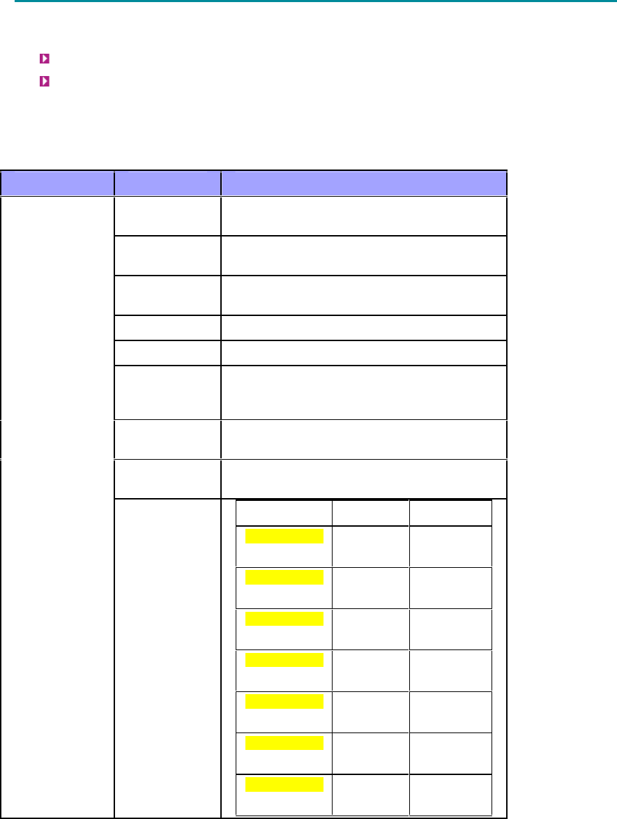
Conventions
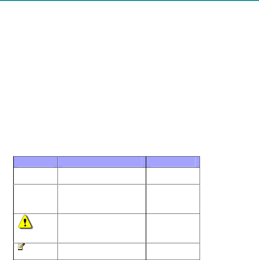
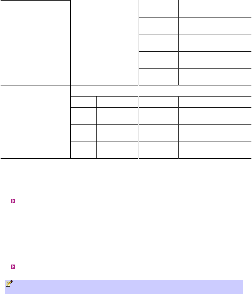
This guide uses the following typographical conventions:
Convention Meaning Example
Bold Command, menu, icon,
button, and field
Click the Next
button.
"To" in bold
face and at
the beginning
of a sentence
Introduces a numbered
procedure
To download a
SW file:
Warning that provides
information that can prevent
and avoid bodily or
mechanical harm
--
Note that provides useful
information
--

7
SYSTEM OVERVIEW
EasyST 4.9 (hereafter referred to simply as EasyST) is a revolutionary, self-install, compact, indoor
WiMAX subscriber access device. EasyST delivers high-speed Internet services to subscribers' IP-
enabled devices through its wireless-based interface with WiMAX networks (i.e. ISP's base station).
EasyST is designed to work with the AS.MAX Base Station. EasyST implements Intel Corporation’s
Pro/Wireless 5116 broadband interface. EasyST is designed for the residential and small enterprise
markets, providing high-speed broadband Internet access and a Fast Ethernet connection to the
subscriber's local area network (LAN).
EasyST can be installed (indoors) by end users within minutes without the need for costly
professional installations.
EasyST operates in the 4.9 to 5.0 GHz frequency band in time division duplexing (TDD) mode.
EasyST supports IP services at uplink and downlink over-the-air speeds of up to 37 Mbps over a
channel bandwidth of 10 MHz, and up to 18 Mbps over a channel bandwidth of 5 MHz.
EasyST uses the OFDM signaling format, providing non line-of-sight (NLOS) performance. EasyST
utilizes QAM, QPSK, and BPSK modulation technologies by modulating transmitted signals and
demodulating the received signals where the original digital message can be recovered. The use of
adaptive modulation allows EasyST to optimize throughput, yielding higher throughputs while also
covering long distances.
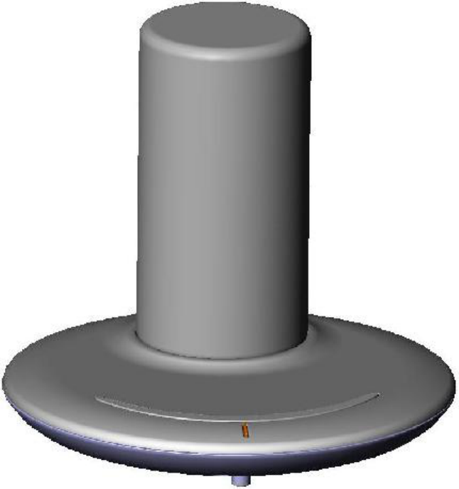
EasyST is deployed with a clip-on antenna for providing the wireless interface with the base station.
The antenna is supplied attached to the EasyST's top panel.
The EasyST's compact design allows it to be easily mounted alongside the end-user's PC by simply
placing it on a desktop. Easy-to-read radio signal strength LED indicators on the EasyST's top panel
enables the end user to position the device in the optimum location, ensuring service availability
and reliability, whilst increasing service speed and reducing network load.
EasyST provides 10/100BaseT interface with the subscriber's LAN. In addition, the EasyST provides
an interface for adding plug-in expansion modules to provide support for features (planned for
future) such as: Wi-Fi and LAN switch; VoIP and battery backup.
EasyST is powered by an AC/DC power adapter that is plugged into any standard electrical wall
outlet. The power adapter provides interchangeable plug prongs to suit country electrical wall
sockets.
EasyST can be managed by Airspan'sAS.MAX Web-based management system using standard Web
browsers that access the Web server located on the EasyST (refer to the WiMAX Web-based
Management User's Guide), or alternatively, by an SNMP-based network management system
(Netspan) using standard and proprietary MIBs. In addition, external third-party management
systems such as HP OpenView can also manage the EasyST using these MIBs.
Main Features
The EasyST provides the following main features:
World’s First "Self-Install" WiMAX Subscriber Station
Full Indoor Non-LOS Deployment -- 256 OFDM
No professional installation, simply Plug & Play -- user unpacks, plugs in and surfs
Based on 802.16 ProWireless 5116 Rosedale chip
Designed to sit next to a computer on a desktop
Clip-on antenna containing four 90-degree, high-gain directional antennas providing 360
degree coverage (EasyST selects antenna with best RF reception) -- self pointing for easy
setup by untrained subscriber
Over-the-air rate of 37 Mbps (DL/UL) for a 10-MHz channel (18 Mbps for a 5-MHz channel)
Supports transparent bridging

605-0000-703 EasyST 49 Installation User Guide-Rev D
8
Supports QoS (based on IP addresses, protocols, applications, DiffServ/TOS, 802.1p)
Configuration for Operator Network via integrated Smart Card (SIM) reader -- planned for
future
Stackable “CD” Style Design for adding plug-in expansion modules for the following
interfaces:
o Integrated IEEE 802.11b/g Wi-Fi access point and LAN switch -- planned for future
o Integrated VoIP allowing connection of 2 conventional telephones (POTS) and battery
backup -- planned for future
Customer Benefits
The EasyST offers the following customer benefits:
Self-install -- fast, easy and simple installation
Provides signal strength LEDs for quick and simple alignment with providers base station
Compact unit occupying little space
Based on the latest wireless technology WiMAX IEEE 802.16 standard
High throughput providing fast access at burst data rates of up to 37 Mbps over a channel
bandwidth of 10 MHz, and up to 18 Mbps over a channel bandwidth of 5 MHz
Low cost
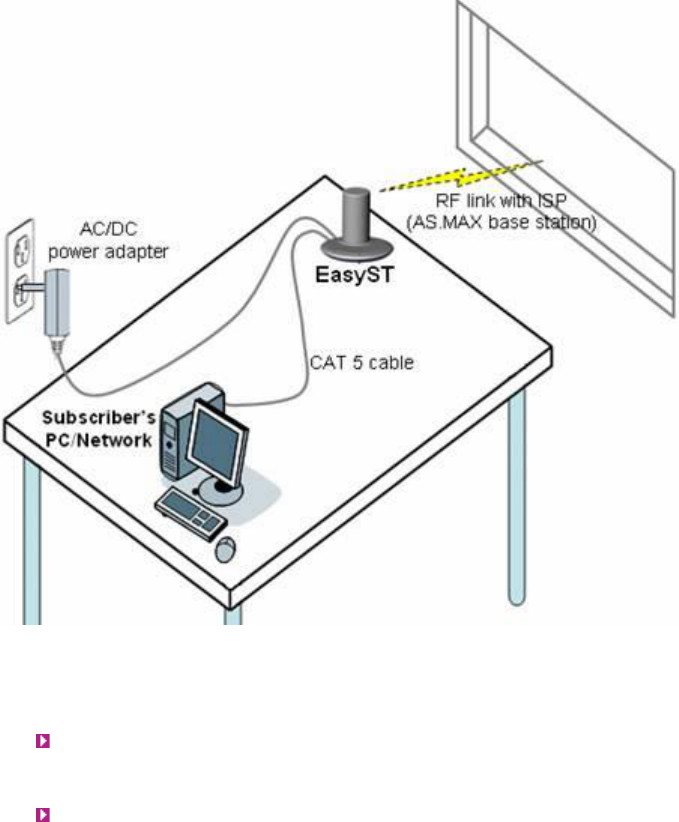
Architecture
The EasyST is a self-install indoor unit requiring no professional installation. The EasyST
architecture includes the following components:
EasyST module with clip-on antenna
AC/DC power adapter with interchangeable plug prongs -- plugs into a standard electrical
wall outlet (110/240 VAC, 50/60 Hz) and supplies the EasyST with 6 VDC power
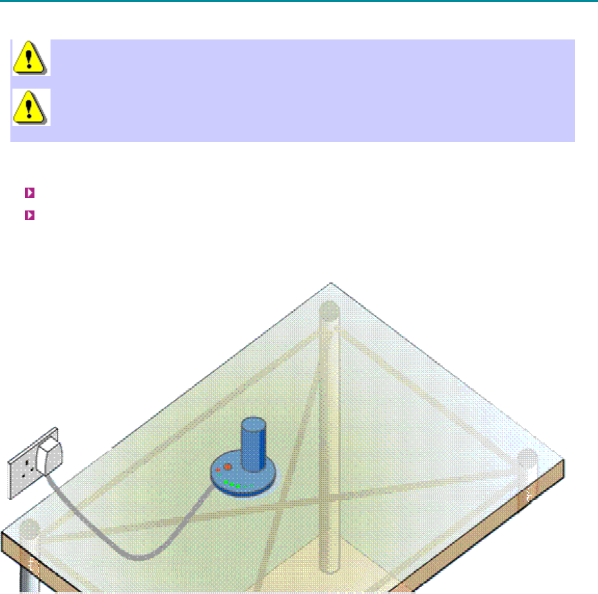
The EasyST provides a fast and easy mounting method by allowing you to simply place it on a
desktop/table, as displayed below.
System Overview
9
EasyST Models
The EasyST is available in the following optional deployment models:
EasyST with clip-on antenna containing four high-gain, integrated flat panel, 90-degree
directional antennas, providing 360 degree coverage. EasyST selects the antenna with best
RF reception with the BS by using the 6-pin Antenna Controller.
EasyST providing plug-in expansion modules supporting the following interfaces:
o Wi-Fi and LAN switch (planned for future)
o VoIP and battery backup (planned for future)
EasyST Block Diagram
The figure below displays the EasyST block diagram:
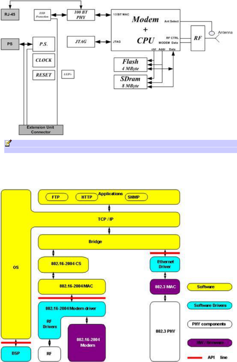
605-0000-703 EasyST 49 Installation User Guide-Rev D
10
Note: EasyST uses the antenna switch to select one of the four 90-degree antennas of the
clip-on antenna.
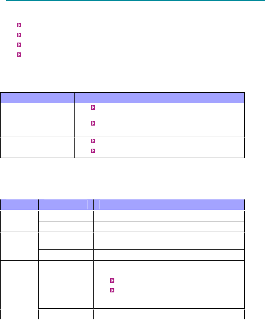
EasyST Protocols Stack
The figure below displays a block diagram of the EasyST's network architecture, designed as a
hierarchy of protocols (i.e. protocol stack) implemented in the communication network.

System Overview
11
Theory of Operation
For basic operation, the EasyST requires no initial configuration--simply plug and play.
Configuration is automatically performed over the air by the BS. The EasyST is preconfigured
by the operator at the BS (using Netspan) with service flow parameters such as the maximum
information rate, the committed information rate, the maximum latency, and maximum jitter.
These configuration parameters are stored in Netspan's database corresponding to the
EasyST's MAC address.
Before any communication between EasyST and BS can occur, the EasyST must be positioned
in a location that provides sufficient RF reception.
To join a network, the EasyST needs to perform a few tasks. First, the "Network Entry" process
(defined in IEEE 802.16-2004) begins with the EasyST scanning for a downlink (DL) signal from
the base station, and then synchronizing to the DL channel. Thereafter the EasyST can start the
process of initial ranging, which alerts the BS to the presence of the EasyST and establishment
of management connections to obtain basic and primary management connection IDs (CID)
from the BS. After the CIDs have been obtained, the EasyST commences authorization and key
exchange. In the final stage, the EasyST registers at the base station and thereafter obtains
the IP address, time of day and the configuration file from the BS.
During Network entry, the EasyST sends the BS its MAC address. The BS then accesses
Netspan's database (via SNMP) and checks whether the EasyST's MAC address appears in the
database. If it locates the MAC address, the BS retrieves all the EasyST's configuration
parameters (service flows) from the database and downloads them to the EasyST device.
See Also:
EasyST specifications

12
GETTING STARTED
Before installing your EasyST, read the following sections to ensure that no EasyST items are
missing, minimum computer requirements are fulfilled, and you have the required installation tools.
Package Contents
The EasyST kit includes the following items:
EasyST module with clip-on antenna
AC/DC power supply adapter
Category 5 Ethernet LAN cable (1.5 meters)
Quick Installation Guide
Note: Examine the AS.MAX shipping container. If you notice any damage, or missing items
as listed in the Packing List, immediately notify the carrier that delivered the unit and contact
an Airspan representative.
Minimum PC Requirements
Ensure that your computer provides an Ethernet interface such as a Network Interface Card (that
provides an RJ-45 port).
13
PHYSICAL DESCRIPTION
This section describes the EasyST's physical description:
Physical Dimensions
Ports
LEDs
LED Button (Planned for Future)
Physical Dimensions
The physical dimensions of the EasyST are listed in the table below:
Parameter Value
Dimensions
(height x width x
depth)
With clip-on antenna: 130 x 145 x 145 mm (5.12 x
5.7 x 5.7 inches)
Without clip-on antenna: 30 x 145 x 145 mm (1.18
x 5.7 x 5.7 inches)
Weight With clip-on antenna: 0.426 kg (approximate)
Without clip-on antenna: 0.3 kg (approximate)
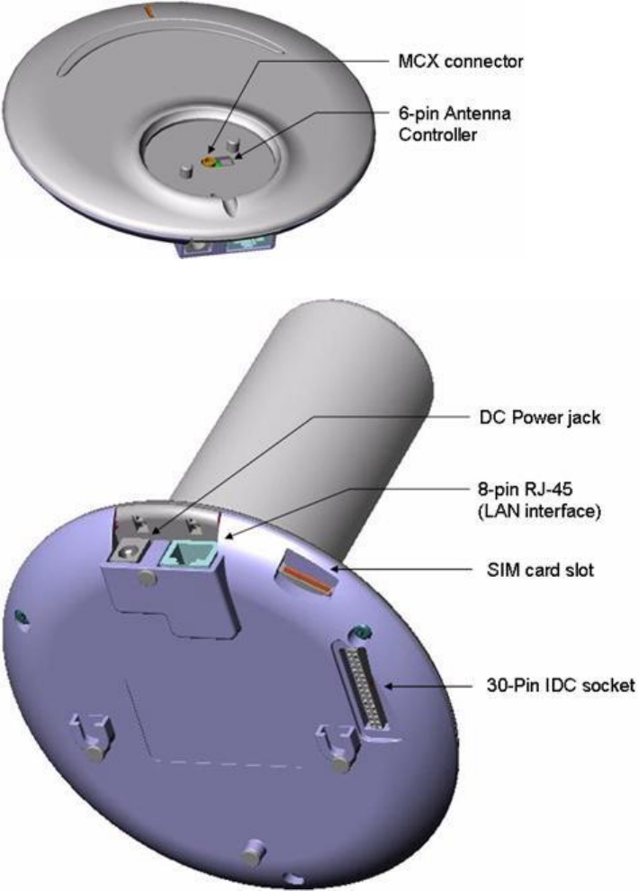
Ports
The EasyST provides various ports on its top, bottom, and side panels, as described in the table
below:
Panel Port Interface
8-pin RJ-45 10/100BaseT Ethernet LAN Side
DC power jack 6 VDC power (supplied by AC/DC power adapter)
6-pin header Integrated Antenna Controller for attaching clip-on
antenna (determines active antenna--1 out of 4)
Top (cover
exposed)
MCX jack Clip-on antenna
30-pin IDC socket Plug-in extension board for the following interfaces
planned for future:
802.11 Wi-Fi and LAN switch
VoIP and Battery Backup
(The IDC socket accepts flat cables)
Bottom
SIM Authentication support (planned for future)
The figures below display the EasyST ports, which are located on the top (with the clip-on antenna
removed) and bottom panel respectively.
605-0000-703 EasyST 49 Installation User Guide-Rev D
14
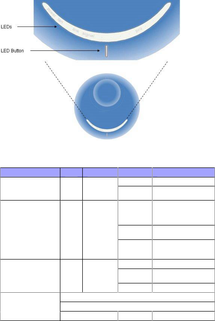
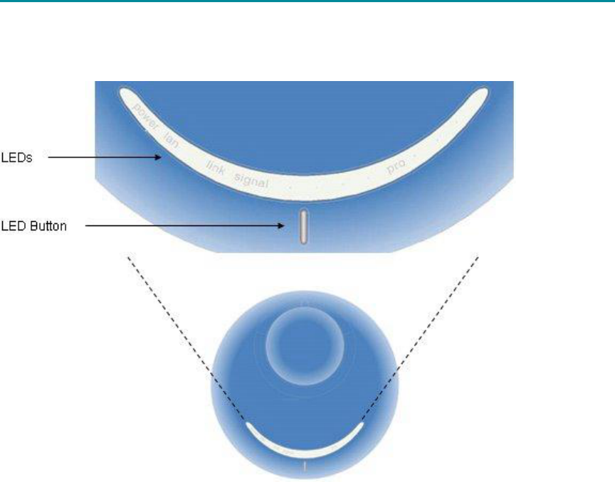
LEDs
The EasyST provides LEDs for indicating the status of various operations. These LEDs are located on
the EasyST's top panel for easy viewing, as shown in the figure below:
Physical Description
15
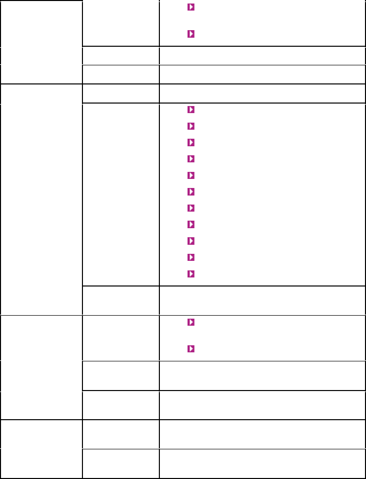
The EasyST LEDs are described in the table below:
LED Color Mode Status Description
On EasyST receiving power power Red
Off No power received by
EasyST
On 10/100BaseT network
device (e.g. PC)
correctly connected to
EasyST
Flashing Active LAN link (i.e.
traffic flow)
lan Green
Off No 10/100BaseT
interface connected to
EasyST
On Active WiMAX link
Flashing Undergoing Network
Entry
link Green
Off No WiMAX link
Customer mode
Average Signal to Noise Ratio (SNR)
signal
Green All LEDs are off
< 5
605-0000-703 EasyST 49 Installation User Guide-Rev D
16
First left-most
LED is on
5 < = SNR < 9
Two left-most
LEDs are on
9 < = SNR < 12
Three left-
most
LEDs are on
12 < = SNR < 16
Four left-most
LEDs are on
16 < = SNR < 22
Five LEDs are
on
22 < =SNR
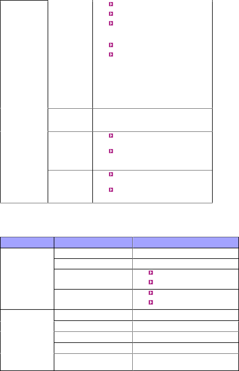
PRO mode
Customer mode
Off
Red Professional
Mode #1
On Modulation and FEC
Green Professional
Mode #2
On RSSI
signal
N/A Professional
Mode #3
N/A N/A
LED Button
The LED button (planned for the future) located below the LED lights provides the following
functionality:
Toggles between LED modes: Each time you press the button, the LED mode changes:
o Customer (standard mode): Signal LEDs display SNR value as described in the table
above
o Professional #1: provides technician with indication of RSSI
o Professional #2: provides technician with an indication of the modulation and FEC used in
the uplink (planned for future release)
o Professional #3: provides technician with indication of downlink throughput (planned for
future release)
Resets EasyST to factory default settings: To reset to default settings, hold down the
button for 10 seconds
Note: When any of the Professional modes are continually active for 30 seconds, the mode
returns automatically to the Customer mode.
17
CONNECTING EASYST TO A PC
EasyST provides 10/100BaseT (Fast Ethernet) interface with the subscriber's network. The
connectivity is performed through the supplied Category 5 Ethernet cable consisting of 8-pin RJ-45
connectors on either end.
The EasyST-to-computer cable setup is listed below:
Cable: straight-through CAT 5 STP Ethernet cable
Connector: 8-pin RJ-45
Connector pinouts (for both ends):
Pin Function
1 Tx+
2 Tx-
3 Rx+
6 Rx-
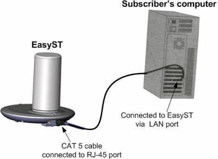
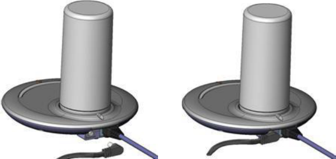
To connect EasyST to the subscriber's network:
1. Plug the RJ-45 male connector, located at one end of the Category 5 Ethernet cable, into
the EasyST's 8-pin RJ-45 port.
2. Plug the RJ-45 male connector, located at the other end of the Category 5 Ethernet cable,
into your computer's LAN port.
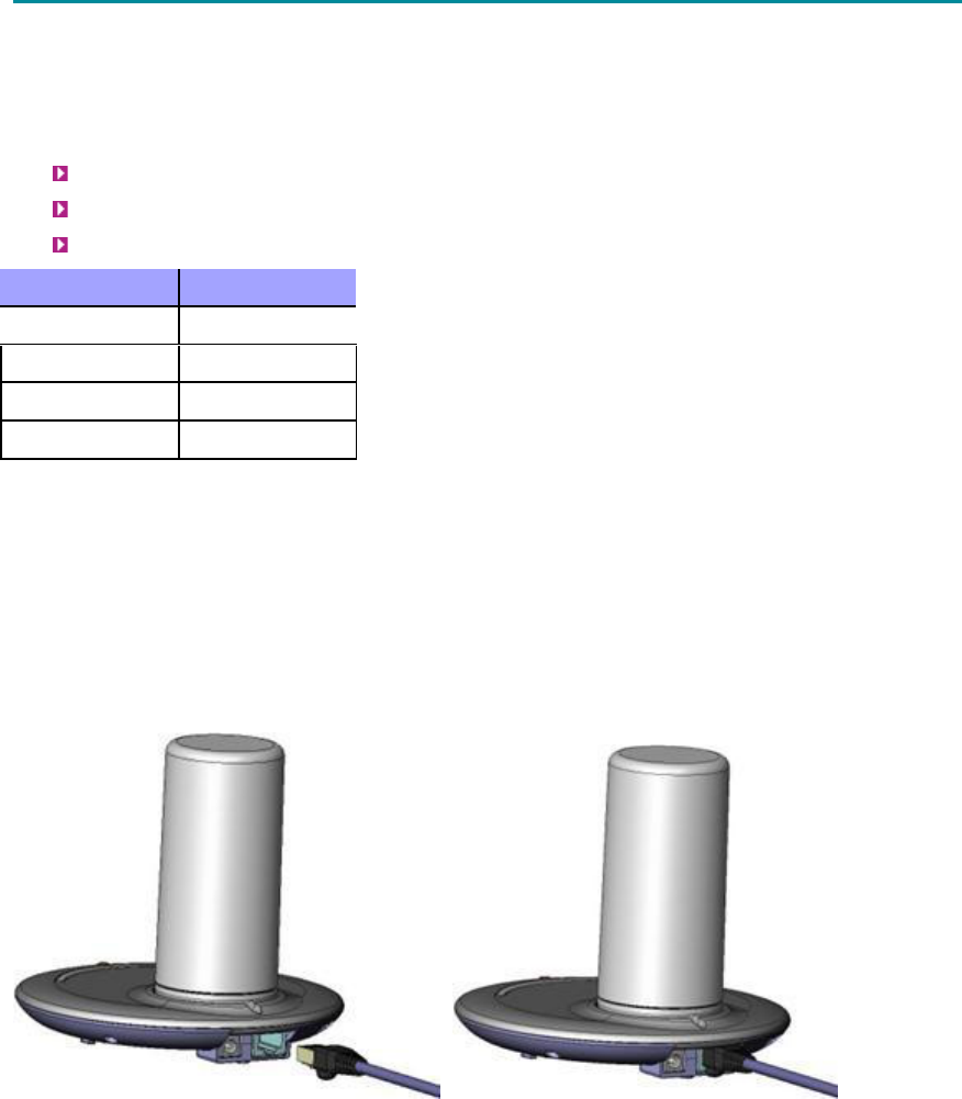
The figures below illustrate the EasyST-to-computer cable connection:
605-0000-703 EasyST 49 Installation User Guide-Rev D
18
19
CONNECTING EASYST TO POWER
EasyST is powered by an AC/DC power supply adapter which supplies the EasyST with 6 VDC and 4
Amperes. The AC/DC adapter is simply plugged into a standard electrical wall outlet (110/240 VAC;
50/60 Hz).
The power adapter provides interchangeable prongs (e.g. American vs. European) that can be
replaced to suit country electrical standards in which the EasyST is being installed. To view the
AC/DC power adapter specifications, see AC/DC Power Adapter Specifications.
Note: Any AC/DC power adapter complying with Class 2 and LPS, and safety approved
according to national regulations, and that provides rated input of 100-240 V, 50/60 Hz, 0.4 A
and output of 6 V, 4 A DC, may be used for powering the EasyST.
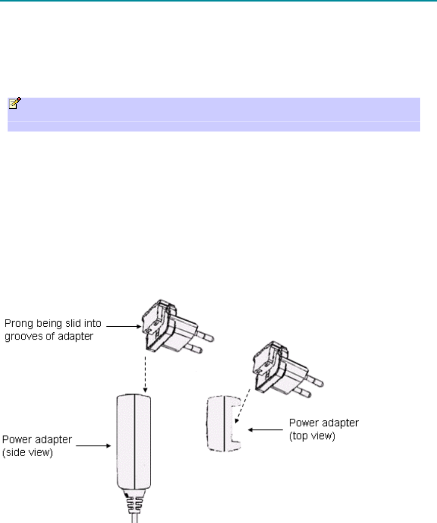
Changing the AC/DC Power Adapter's Prongs
The AC/DC power adapter provides interchangeable prongs to suit electrical wall outlet sockets in
the country in which the EasyST is being installed.
To change the plug prongs:
1. Remove the prongs by first moving (with the help of a pen) the LOCK/OPEN switch to
OPEN position, and then gently sliding the prongs upwards, away from the power cord.
2. Align the desired prongs with the adapter's prong groove, and then slide the prongs onto
the adapter in the orientation as shown in the figure below. Ensure that the prongs reach
the end of the prong groove.
3. Secure the prong in place by moving (with the help of a pen) the LOCK/OPEN switch to
LOCK position.
Connecting EasyST to AC/DC Power Adapter
After you have attached the plug prongs suitable to your country's electrical wall socket, you are
ready to connect the EasyST to the electrical wall outlet.
605-0000-703 EasyST 49 Installation User Guide-Rev D
20
To connect the EasyST to the power supply:
1. Before plugging the power cord into the electrical wall outlet, plug the AC/DC power
adapter's power cable (i.e. DC power jack) into the EasyST's DC power socket.
2. Plug the prongs of the AC/DC power adapter into the electrical wall outlet.
21
MOUNTING EASYST
Warning: The EasyST must be mounted indoors.
Warning: To prevent a fire hazard caused by overheating, do not place the EasyST on
a carpeted surface where airflow is restricted.
EasyST is a self-install indoor unit, requiring no professional technician. EasyST must be mounted
indoors in a location that provides:
High quality RF reception with the Internet service provider (i.e. base station)
Accessibility to power supply and LAN network with regards to cable lengths
The EasyST offers quick and easy mounting by allowing you to simply place it horizontally on a
desktop (as shown in the figure below). The EasyST radio contains integrated rubber feet (pads) on
the bottom panel, which provide cushioning as well as insulation from static electricity.
22
OPTIMIZING PERFORMANCE
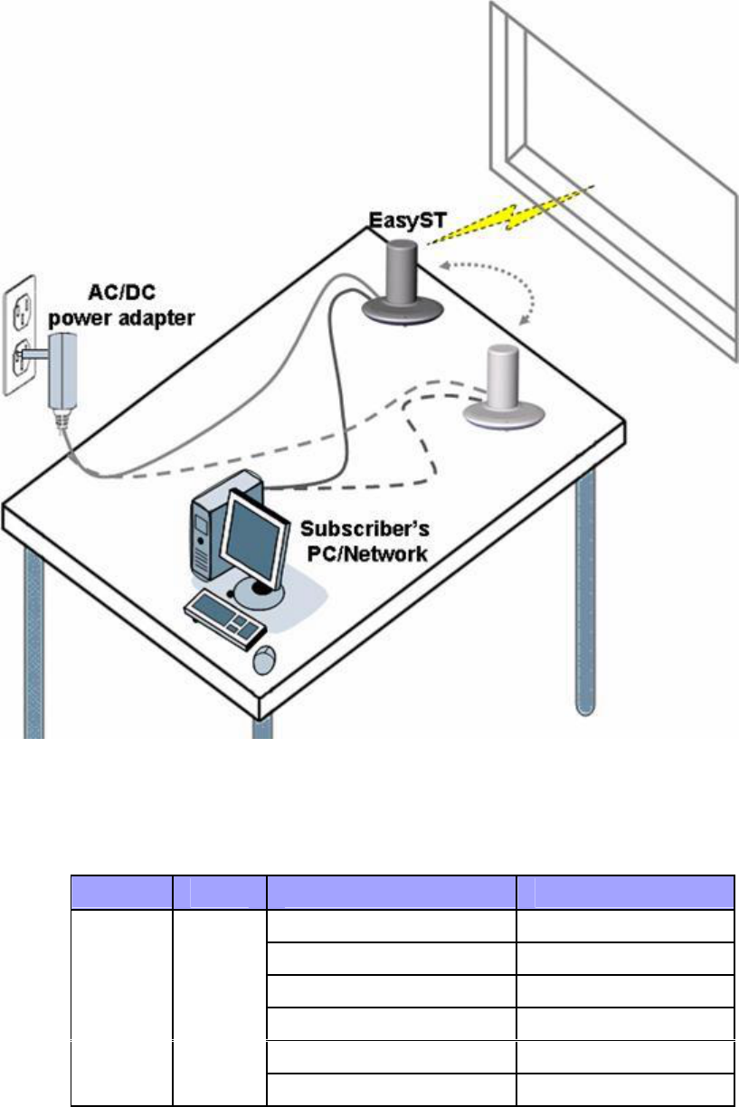
To ensure a reliable, secure, and fast connection with your Internet Service Provider (ISP), you
need to place your EasyST in a position that provides the best RF reception with the ISP (i.e. base
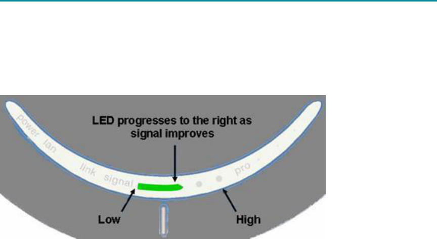
station). To help you locate the best position, EasyST provides you with a LED indicator that
indicates the strength of the RF signal with your ISP. This LED is labeled signal and is located on
the EasyST's top panel.
As the signal strength increases, so the signal LED line progresses to the right, as illustrated below.
Therefore, for optimal reception, simply move your EasyST to the position that produces the longest
signal LED line.
Optimizing Performance
23
The signal LED indicates the strength of the signal by measuring the signal-to-noise ratio (SNR).
SNR indicates received signal strength relative to background noise. The ratio is usually measured
in decibels (dB). The higher the SNR ratio--the better the communication.
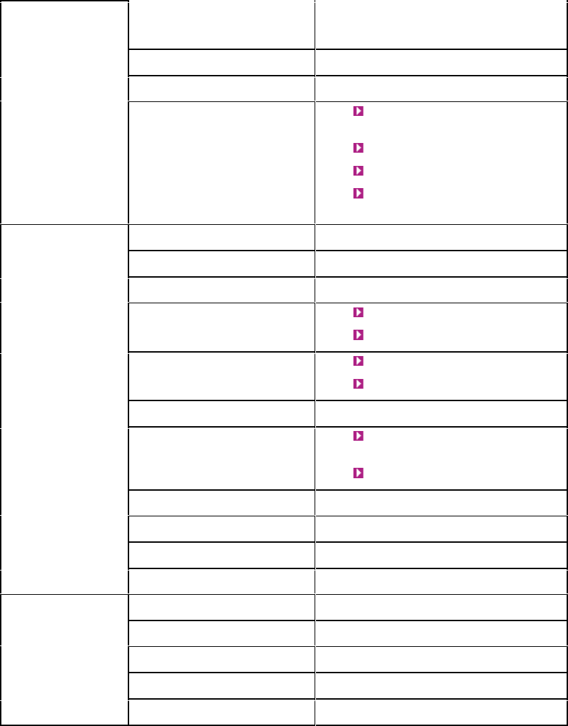
The table below describes the EasyST signal LED with regards to SNR values:
LED Color Status Average SNR (dB)
All LEDs are off Avg. SNR < 5
First left-most LED is on 5 < = Avg. SNR < 9
Two left-most LEDs are on 9 < = Avg. SNR < 12
Three left-most LEDs are on 12 < = Avg. SNR < 16
Four left-most LEDs are on 16 < = Avg. SNR < 22
signal Green
Five LEDs are on 22 < = Avg. SNR
24
RESETTING TO DEFAULT SETTINGS
A future release of the EasyST will allow you to apply factory default configuration settings to the
EasyST. This is performed by pressing the LED button (located below the LED lights on the top
panel) continuously for at least 10 seconds.
25
ATTACHING CLIP-ON ANTENNA
Warning: Before attaching the clip-on antenna, ensure that the EasyST is not
connected to the power source. Do not connect and disconnect antenna while the power is on.
This can cause irreversible damage to the EasyST.
The EasyST is supplied with the clip-on antenna already attached to the EasyST. However, in cases
where it may have accidentally being removed, you can re-attach it by following the procedure
described below.
Note: Later EasyST models provide a screw for securing the antenna to the EasyST.
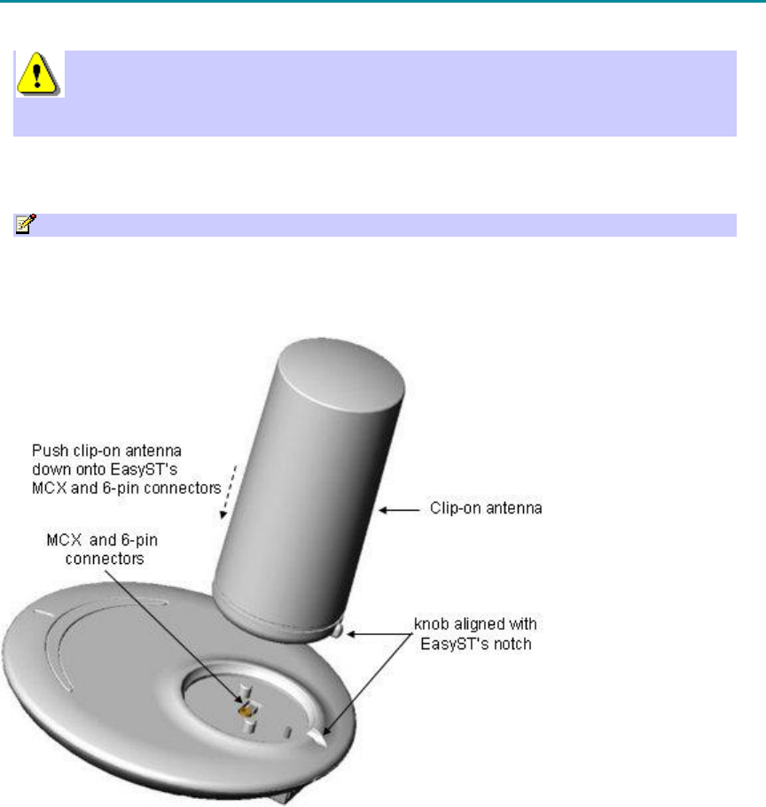
To replace the clip-on antenna:
1. Align the clip-on antenna's knob with the EasyST's notch, as shown in the figure below.
2. Gently push the antenna down onto the EasyST so that the MCX and 6-pin connectors plug
into their respective receptacles, and that the antenna's knob sits firmly into the EasyST's
notch.
605-0000-703 EasyST 49 Installation User Guide-Rev D
26
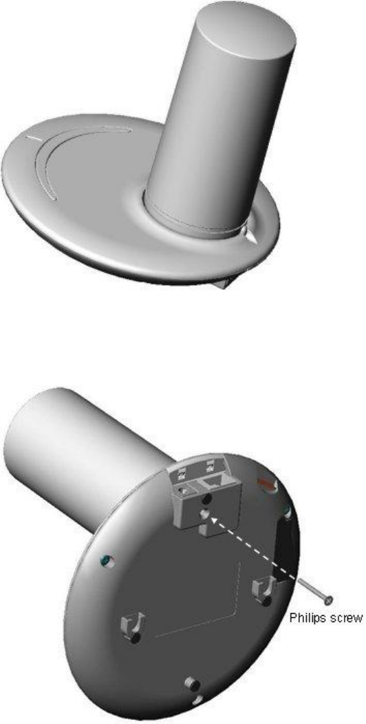
3. For customers possessing EasyST models that implement a screw mechanism for securing
the antenna to the EasyST, continue with the following steps:
a. Flip the EasyST over so that its rear panel is visible. Insert the M3 25-mm flat-head Philips
screw (supplied) into the hole that's located on the rear panel, behind the RJ-45 and DC
power connectors, as shown in the figure below.
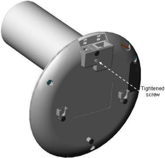
b. Using a Philips screwdriver, tighten the screw so that the antenna is firmly attached to the
EasyST.
Attaching Clip-On Antenna
27
28
SPECIFICATIONS
This section lists the specifications of the following:
EasyST
AC/DC Power Adapter
EasyST Specifications
The EasyST's specifications are listed in the table below:
Category Parameter Value
Frequency
band:
4.9 to 5.0 GHz
RF multiple
access scheme:
256 OFDM
Duplex
method:
Time Division Duplexing (TDD)
Channel size: 5 MHz or 10 MHz
Tx power: up to 17 dBm
Antenna type: Clip-on, integrated 4 x 90-degree high-
gain 7-dBi directional antennas (EasyST
selects antenna with best RF reception)
Modulation
method:
BPSK, QPSK, 16QAM and 64QAM
Channel access
method:
Adaptive TDMA
Radio
Technology
Receiver (Rx)
sensitivity:
Modulation 5 MHz 10 MHz
3/4 64QAM: -80.5
dBm
-77.4
dBm
2/3 64QAM -82.0
dBm
-78.9
dBm
3/4 16QAM: -86.2
dBm
-83.1
dBm
1/2 16QAM: -89.5
dBm
-86.4
dBm
3/4 QPSK: -92.5
dBm
-89.4
dBm
1/2 QPSK: -95.0
dBm
-91.9
dBm
1/2 BPSK: -97.5
dBm
-94.4
dBm
Specifications
29
Radio: WiMAX Forum Certified™ for IEEE
802.16-2004
TELEC
Safety: EN/IEC/UL 60950
Standards
Compliance
Environmental:
EN 300 019-2-x
Protocols: Transparent Bridging
QoS: IP type of service
Protocol
IP source address
IP destination address
Protocol source port
Protocol destination port
Ethernet destination MAC address
Ethernet source MAC address
Ethertype/IEEE 802.2 SAP
IEEE 802.1D User Priority
IEEE 802.1Q VLAN ID
Networking
Default IP
address:
10.0.0.1
Remote: SNMP-based (standard and
private MIBs)
Web-based (HTTP)
Software
upgrade:
FTP based
Management
Management
tools:
GUI based for SNMP- and Web-based
management
Operating
temperature:
0°C to +45°C (32°F to 113°F)
Environmental
Conditions
Operating
humidity:
+30°C (86°F), RH=90% to 100%
605-0000-703 EasyST 49 Installation User Guide-Rev D
30
Interfaces: 10/100BaseT (8-pin RJ-45)
DC power (DC power jack)
RF: Clip-on antenna (MCX
connector and 6-pin Antenna
Controller)
SIM slot (planned for future)
Plug-in expansion module through
30-pin IDC socket for the
following interfaces:
o 802.11 Wi-Fi -- planned for future
o LAN switch -- planned for future
o VoIP and Battery Backup --
planned for future
Power
requirements:
6 VDC, 4A, supplied by AC/DC power
adapter plugged into a standard electrical
wall outlet (110/240 VAC, 50/60 Hz)
Dimensions: With clip-on antenna: 130 x 145 x
145 mm (5.12 x 5.7 x 5.7 inches)
Without clip-on antenna: 30 x 145
x 145 mm (1.18 x 5.7 x 5.7
inches)
Mechanical
and
Electrical
Weight: With clip-on antenna: 0.426 kg
(approximate)
Without clip-on antenna: 0.3 kg
(approximate)
Power Adapter Specifications
The specifications of the AC/DC power adapter are listed in the table below:
Category Parameter Value
Input voltage 90 to 264 VAC
Input frequency 47 to 63 Hz
Input inrush current 30 A at 115 VAC
60 A at 230 VAC
Input
Earth leakage 0.4 mA max. @ 115 VAC
0.8 mA max. @ 230 VAC
Output rating 6V / 4A
Output voltage accuracy ± 2% max.
Max. output power 24W
Line regulation ± 1% max.
Output
Load regulation (full to half
load)
6 ˜6.5V
Specifications
31
Transient response (full to
half load)
± 1% max. dev.
500 uS recovery
Temperature coeffeicient ± 0.04% / °C
Ripple and noise 100mVp-p max
Protections Over voltage protection
(output voltage 7.5V)
Over power protection
Short circuit protection
Over current protection:
130% ˜ 160%
Efficiency 70% typical at full load
Hold-up time 5 ms @ 115 VAC full load
EMI / RFI VDE and FCC Class B limits
Dielectric withstand Input/output: 3000 Vac
Input/Ground: 1500 Vac
Safety meet UL/CUL UL60950
CE EN55022
Switching frequency 100 kHz
Connector for radio Input: interchangeable
prongs
Output: DC power jack
Cable length 1.25 m
Dimensions 86 × 46 × 33 mm
Weight 180 g
General
MTBF 100,000 hours (MIL-HDBK-217F)
Operating temperature 0 to +40°C
Storage temperature -20 to +85°C
Humidity 5 to 95% RH non-condensing
Vibration 2.4G, 5 to 500 Hz
Environmental
Cooling Free air convection

32
TROUBLESHOOTING
Once you have connected the EasyST to the subscriber's LAN and to the power supply, you can
verify whether you have cabled the EasyST correctly by checking the EasyST LED status:
Connection
LED Color
Correct
Status
Troubleshooting
Power power Red On If the power LED is off, recheck the power cabling and
that power exists at the wall socket.
LAN lan Green
On If the lan LED is off, recheck the LAN cabling; ensure that
you have connected it to the correct LAN port on your PC
and that your network connection on your PC is enabled.

33
GENERAL
REVISIONS
Revision
Level
Date Main Changes
A 16-10-
2005
Initial Document
B 07-03-
2006
Warning changed to 20 cm
C 28-3-
2006
Warning Removed
D 01-05-
2006
FCC Statement, Warning, additions

605-0000-703 EasyST 49 Installation User Guide-Rev D
34
CONTACT INFORMATION
UK Office for sales and general enquiries
Airspan Communications Ltd
Cambridge House
Oxford Road
Uxbridge
Middlesex
UB8 1UN
Call +44 (0) 1895 467100
Fax +44 (0) 1895 467101
email sales@ airspan.com
Internet: Airspan.com
Customer Service Help-Desk for customer service emergency
Airspan Communications Limited
Cambridge House
Oxford Road
Uxbridge
Middlesex
UB8 1UN
Int. Tel: +44 (0) 1895 467 467
Int. Fax: +44 (0) 1895 467 472
E-mail: Support@Airspan.com

General
35
COPYRIGHT INFORMATION
1. Airspan Networks Inc 2005
2. The information in this document is proprietary to Airspan Networks Inc. This document
may not in whole or in part be copied, reproduced, or reduced to any medium without prior
consent, in writing, from Airspan Networks Incorporated.
3. This manual is subject to revision.
4. All rights reserved.
5. Right of modification reserved.
6. This manual is supplied without liability for errors or omissions.
7. No part of this manual may be reproduced or used except as authorised by contract or
other written permission.
8. This equipment is conditioned by the requirement that no modifications are made to the
equipment unless the changes or modifications are expressly approved by the Airspan
Communications Corporation
9. Prerequisite skills: Personnel installing, commissioning, and maintaining the Airspan
products must have a basic knowledge of telephony and radio communications, and have
experience in installing, commissioning and maintaining telecommunications products.
Airspan provides a range of comprehensive training courses specifically aimed at providing
operators/users of Airspan products with the prerequisite skills to install, commission and or
maintain the product. The courses are tailored to provide the level of training required by
the operator/user.
10. AS4000, AS4020 and AS8200 are brands of Airspan Networks Inc

605-0000-703 EasyST 49 Installation User Guide-Rev D
36
WARNINGS AND CAUTIONS
1. Disclaimer
Every effort has been made to ensure the accuracy of the material provided herein; however,
Airspan assumes no responsibility regarding the use of the material. Additionally, Airspan
makes no representations or warranties, either expressed or implied, regarding the contents
of this product. Airspan Networks Inc. shall not be liable for any misuse regarding this
product.
Any product performance limits stated within this document are for information purposes
only and should be considered as indicative.
1.1 Safety Warnings
1. Read this User Manual and follow all operating and safety instructions.
2. Keep all product information for future reference.
3. This product is supplied with a grounding power plug. Do not defeat this important safety
feature.
4. Warning: High voltages exist inside the product - do not remove the lid or base: No user
serviceable parts inside.
5. CAUTION: DOUBLE POLE/NEUTRAL FUSING - Always replace the fuse with the correct type
and current rating.
6. Position the power cord to avoid possible damage; do not overload wall outlets.
7. Do not place this product on or near a direct heat source, and avoid placing objects on the
terminal.
8. Do not operate this device near water or in a wet location.
9. Use only a damp cloth for cleaning. Do not use liquid or aerosol cleaners. Disconnect the
power before cleaning.
10. Protect the terminal by disconnecting the power if not used for long periods.
11. Mount the terminal in a Telco rack on a stable horizontal surface.
12. The radio antenna units must not be located near power lines or other electrical power
circuits.
13. The radio transceiver must be properly grounded to protect against power surges and
accumulated static electricity. It is the user’s responsibility to install this device in
accordance with the local electrical codes: correct installation procedures for grounding of
the transceiver unit, mast, lead-in wire and discharge unit, location of discharge unit, size
of grounding conductors and connection requirements for grounding electrodes.
14. Installation of the transceiver must be contracted to a professional installer.
15. Disconnect Device. The socket outlet shall be installed near the equipment , easily
accessible and will act as the disconnect for the MacroMAX .
16. When installed in the final configuration, the product must comply with the applicable
Safety Standards and regulatory requirements of the country in which it is installed. If
necessary, consult with the appropriate regulatory agencies and inspection authorities to
ensure compliance.
1.2 Important Warning Symbols
The following symbols may be encountered during installation or troubleshooting. These warning
symbols mean danger. Bodily injury may result if you are not aware of the safety hazards involved
in working with electrical equipment and radio transmitters. Familiarize yourself with standard
safety practices before continuing.
General
37
Electro-Magnetic Radiation High Voltage
605-0000-703 EasyST 49 Installation User Guide-Rev D
38
1.3 Important Service Information
1. Refer all repairs to qualified service personnel. Do not remove the covers or modify any
part of this device, as this will void the warranty.
2. Disconnect the power to this product and return it for service if the following conditions
apply:
a. The terminal does not function after following the operating instructions outlined in
this manual.
b. Liquid has been spilled, a foreign object is inside, or the terminal has been exposed
to rain.
c. The product has been dropped or the housing is damaged.
3. Locate the serial number of the terminal, antenna, and transceiver and record these on
your registration card for future reference. Use the space below to affix serial number
stickers. Also record the MAC address, located on the back of the terminal.
1.4 UL Information
- The equipment must be properly grounded according with NEC and other local safety code
requirements
- Reminder to all the BWA system installers: Attention to Section 820-40 of the NEC which
provides guidelines for proper grounding and, in particular, specifies that the cable ground
shall be connected to the grounding system of the building, as close to the point of cable
entry as is practical.
1.5 CE Notice
The MacroMAX shelf carries the CE mark to demonstrate conformity with the Radio
Equipment and Telecommunications Terminal Equipment and the Mutual recognition of their
conformity (R&TTE) directive 1999/5/EC.
WARNING: This is a class A product. In a domestic environment this product may cause radio
interference in which case the user may be required to take adequate measures.
Installation
The transceiver and antenna equipment must be installed by a qualified professional installer
and must be installed in compliance with regional, national, and local regulations. It is the
responsibility of the system installer and/or system operator to ensure the installed system
does not exceed any operational constraints identified by local regulations.
Refer to the sections in this product User Guide for detailed information about the correct
installation steps to ensure power and frequency settings are set correctly before connecting
the antenna.
Antenna Selection
Refer to the product User Guide for a list of Airspan Networks approved antennas. Antennas
not listed in the User Guide are outside the scope of this Declaration.
CAUTION: European Directive 1999/519/EC details basic restrictions and reference levels on
human exposure to electromagnetic fields as advised by the ICNIRP. The directive states that
adherence to these recommended restrictions and reference levels should provide a high
level of protection as regards the established health effects that may result from exposure to
such fields.
By the very nature of the system design and installation users will not find them selves
within close proximity of the subscriber terminals.
Standards EN50383 and EN50385 are the applicable harmonised standards for EM fields
generated by fixed wireless equipment.
General
39
The Electromagnetic fields generated by the Central Terminal antenna are below the
recommended safe levels at all distances greater than 65 cm from an approved Airspan
antenna.
The safe distance from a non-approved antenna of length D and Sector Angle ä may be
calculated using the formula:
Safe distance, r = 36 / (ð * D * ä)
1.6 European Community, Switzerland, Norway, Iceland, and
Liechtenstein
Declaration of Conformity with Regard to the R&TTE Directive 1999/5/EC
English:
This equipment is in compliance with the essential requirements and other relevant
provisions of Directive 1999/5/EC.
Deutsch:
Dieses Gerät entspricht den grundlegenden Anforderungen und den weiteren
entsprecheneden Vorgaben der Richtlinie 1999/5/EU.
Dansk:
Dette udstyr er i overensstemmelse med de væsentlige krav og andre relevante
bestemmelser i Directiv 1999/5/EF.
Español:
Este equipo cumple con los requisitos esenciales asi como con otras disposiciones de la
Directive 1999/5/EC.
EëëçíéêÜ:
Áõôüò ï åîïðëéóìüò óõììïñöþíåôáé ìå ôéò ïõóéþäåéò áðáéôÞóåéò êáé ôéò ëïéðÝò äéáôÜîåéò ôçò
Ïäçãßáò 1999/5/EÊ.
Français:
Cet appareil est conforme aux exigencies essentialles et aux autres dispositions pertinantes
de la Directive 1999/5/EC.
Íslenska:
Þessi búnaður samrýmist lögboðnum kröfum og öðrum ákvæðum tilskipunar 1999/5/ESB.
Italiano:
Questo apparato é conforme ai requisiti essenziali ed agli altri principi sanciti dalla Direttiva
1999/5/EC.
Nederlands:
Deze apparatuur voldoet aan de belangrijkste eisen en andere voorzieningen van richtlijn
1999/5/EC.
605-0000-703 EasyST 49 Installation User Guide-Rev D
40
Norsk:
Dette utstyret er i samsvar med de grunnleggende krav og andre relevante bestemmelser i
EU-directiv 1999/5/EC.
Português:
Este equipamento satisfaz os requisitos essenciais e outras provisões da Directiva
1999/5/EC.
Suomalainen:
Tämä laite täyttää direktiivin 1999/5/EY oleelliset vaatimukset ja on siinä asetettujen
muidenkin ehtojen mukainen.
Svenska:
Denna utrustning är i överensstämmelse med de väsentliga kraven och andra relevanta
bestämmelser i Direktiv 1999/5/EC.
The Declaration of Conformity related to this product can be obtained from
product_management@Airspan.com
1.7 CAUTION
Any modifications to this device not expressly authorised by the manufacturer could void the
user's authority to operate this device.
Responsible party for compliance is:
David Mann, Airspan Networks Inc.,Cambridge House, Oxford Rd, Uxbridge, Middlesex,
England, UB8 1UN. Telephone (44) 1 895 467450.
1.8 Lightning Protection
WARNING: The following notes are general recommendations for the system. The wireless
equipment should be installed by a qualified professional installer and must follow local and
national codes for electrical grounding and safety. Failure to meet safety requirements
and/or use of non-standard practices and procedures could result in personal injury and
damage to equipment. A direct lightning strike may cause serious damage even if these
guidelines are followed.
All outdoor wireless equipment is susceptible to lightning damage from a direct hit or induced
current from a near strike. Lightning protection and grounding practices in local and national
electrical codes serve to minimize equipment damage, service outages, and serious injury.
Reasons for lightning damage are summarized as:
- Poorly grounded tower/antenna sites that can conduct high lightning strike energy into
equipment.
- Lack of properly installed lightning protection equipment that can cause equipment failures
from lightning induced currents.
A lighting protection system provides a means by which the energy may enter earth without
passing through and damaging parts of a structure. A lightning protection system does not
prevent lightning from striking; it provides a means for controlling it and preventing damage
by providing a low resistance path for the discharge of energy to travel safely to ground.
Improperly grounded connections are also a source of noise that can cause sensitive
equipment to malfunction.
General
41
A good tower grounding system disperses most of the surge energy from a tower strike away
from the building and equipment. The remaining energy on the RF cable shield and center
conductor can be directed safely to ground by using a lightning arrestor in series with the RF
cable.
To limit the equipment damage due to a lightning strike, the following practices are
recommended for the wireless system:
- Provide direct grounding from the antenna mounting bracket, the radio and antenna and
the lightning arrestors to the same ground point at the base of the tower or a ground bus on
the building. Use the grounding screws on the antenna bracket and the radio and antenna for
terminating the ground wires.
- Install one RF lightning protector between the radio and antenna in series with the RF
cable.
- A lightning arrestor in series with the RF cable at the point of entry to the building.
- Install a lightning arrestor in series with the IF cable at the transceiver on the tower/mast.
- The AC wall outlet ground for the MacroMAX terminal must be connected to the same
grounding system as the radio and antenna lightning protectors.
42
GLOSSARY
A
AP: Access Point (e.g. WiFi AP)
B
BPSK: Binary Phase Shift Keying
BS: Base Station (e.g. WiMAX BS)
BWA: Broadband Wireless Access
C
CID: Connection IDs
CPE: Customer Premises Equipment (interchangeable with ST)
D
dB: Decibel
dBm: Power ratio in dB (decibel) of the measured power referenced to one milliwatt
DHCP: Dynamic Host Configuration Protocol
DL: Downlink
F
FDD: Frequency Division Duplex
FEC: Forward Error Correction
FTP: File Transfer Protocol
G
GHz: Gigahertz
GW: Gateway
H
H-FDD: Half duplex FDD
HTTP: HyperText Transfer Protocol
I
IAD: Integrated Access Device
IP: Internet Protocol
ISP: Internet Service Provider
Glossary
43
L
LAN: Local-Area Network
M
MAC: Media Access Controller. The next layer up from the PHY.
Mbit/s: Megabits per second
MHz: Megahertz (one million cycles per second)
MIB: Management Information Base
N
NLOS: Non Line of Sight radio propagation path
O
ODU: Outdoor unit associated with an ST
OFDM: Orthogonal Frequency Division Multiplexing
P
PHY: The physical layer associated with the WiMAX interconnection stack
POTS: Plain old telephone service
Q
QAM: Quadrature Amplitude Modulation
QoS: Quality of Service, which is used to specify level of data throughput
QPSK: Quadrature Phase Shift Keying
R
RF: Radio frequency
Rx: Receive
S
SF: Service Flow
SIM: Subscriber Identity Module
SNMP: Simple Network Management Protocol
SNR: Signal-to-Noise Ratio
ST: Subscriber terminal (interchangeable with CPE or SS)
SW: Software
T
605-0000-703 EasyST 49 Installation User Guide-Rev D
44
TDD: Time Division Duplex
TDMA: Time Division Multiple Access. Technology for delivering digital wireless service using time-
division multiplexing (TDM)
Tx: Transmit
U
UGS: Unsolicited Grant Service used to provide fixed bandwidth slots on the uplink for an ST to
transmit data at regular intervals. The bandwidth should be used by the UGS SF, however
the final decision of which SF (if any) uses the bandwidth slot is made by the ST.
V
VoIP: Voice-over-Internet Protocol
W
WBM: Web-based management
Wi-Fi: Wireless Fidelity
WiMAX: WiMAX is a wireless industry coalition whose members are organized to advance IEEE
802.16 standards for broadband wireless access (BWA) networks.
45
INDEX
A
Alignment of EasyST .............................. 22
Antenna Alignment ................................ 22
B
Bandwidth Speeds ................................... 7
BPSK ..................................................... 7
C
Changing Power Adapter Plug Prongs........ 19
Clip-On Antenna, Replacing ..................... 25
Components............................................ 7
Connecting EasyST
Clip-on Antenna.................................. 25
To PC ................................................ 17
To Power Adapter................................ 19
D
Dimensions, Physical .............................. 13
E
EasyST Models ........................................ 7
EasyST Specifications ............................. 28
F
Factory Defaults, Resetting ..................... 24
L
LED Button ........................................... 13
LEDs, Description................................... 13
M
Minimum PC Requirements...................... 12
Modulation Technique............................... 7
Mounting .............................................. 21
O
Operating Frequency ................................ 7
Optimizing Performance.......................... 22
Overview ................................................ 7
P
Package Contents .................................. 12
Physical Dimensions ............................... 13
Ports, Description .................................. 13
Power Adapter
Changing Prongs................................. 19
Connecting to EasyST .......................... 19
Specifications ..................................... 28
Q
QAM ...................................................... 7
QPSK ..................................................... 7
R
Replacing Clip-On Antenna ...................... 25
Resetting to Factory Defaults................... 24
S
SNR, Viewing ........................................ 22
T
Theory of Operation ................................. 7
Troubleshooting..................................... 32

46
How to find out
more
about
Airspan products
and solutions
Airspan has offices in the following
countries:
Europe
Czech Republic
Poland
Russia
United Kingdom
Africa
South Africa
Americas
United States
Asia Pacific
Australia
China
Indonesia
Japan
New Zealand
For more information about Airspan, its
products and solutions, please visit our
Web site:
www.airspan.com
Or write to us at one of the addresses
below.
We will be delighted to send you
additional
information on any of our products and
their
applications around the world.
Worldwide Headquarters:
Airspan Networks Inc.
777 Yamato Road, Suite 105
Boca Raton, Florida 33431-4408
USA
Tel: +1 561 893 8670
Fax: +1 561 893 8671
Main Operations:
Airspan Communications Ltd.
Cambridge House, Oxford Road,
Uxbridge, Middlesex UB8 1UN
UK
Tel: +44 (0) 1895 467 100