Airspan Networks ASMAX55 Subscriber (terminal) station User Manual DFS Link instruction
Airspan Networks Inc Subscriber (terminal) station DFS Link instruction
Contents
- 1. Users manual
- 2. DFS Link instructions
DFS Link instructions
L
INK
I
NSTRUCTION
REVISION: A0
---------------------------------------------------------------------------------------
Doc. Link Instruction
Printing Date: 11/05/08 Page 1 of 5
Title:
Link instructions for
5.6GHz DFS System
Rev. ECO
No. Author Description Approved
By Valid
Date
A0
- Zion L. Release Reuven B
10/5/08
.

L
INK
I
NSTRUCTION
REVISION: A0
---------------------------------------------------------------------------------------
Doc. Link Instruction
Printing Date: 11/05/08 Page 2 of 5
1. Required equipment
• 2* Standard PC included Serial port and LAN port.
• Standard HyperTerminal Application.
• 2* SDA 4S.
• P.S 220VAC to 6V DC.
• 2* Ethernet cables.
• Crossed RS-232 cables.
• 2* Y cable.
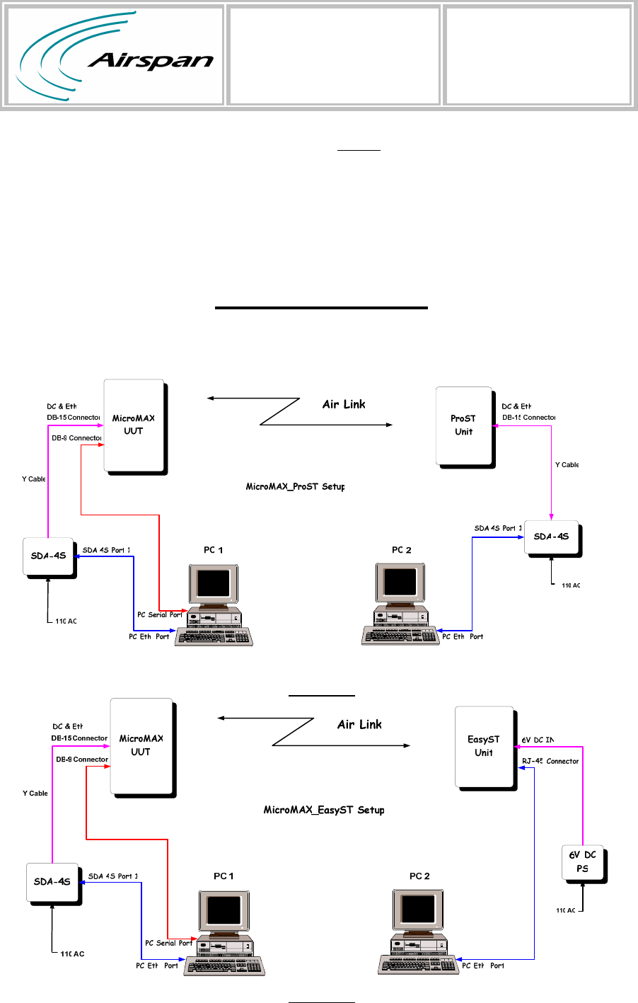
2. Testing Setup
1ProST Setup Figure
• Connect Y cable between SDA 4S DB-15 connector and MicroMAX
DB-15 connector.
• Connect Serial cable between MicroMAX DB-9 connector and PC 1
Serial port.
• Connect LAN cable between SDA 4S port 1 and PC 1 LAN port.
• Connect Y cable between SDA 4S DB-15 connector and ProST
DB-15 connector.
• Connect LAN cable between SDA 4S port 1 and PC 2 LAN port.
2EasyST Setup Figure
• Connect Y cable between SDA 4S DB-15 connector and MicroMAX
DB-15 connector.
• Connect Serial cable between MicroMAX DB-9 connector and PC 1
Serial port.
L
INK
I
NSTRUCTION
REVISION: A0
---------------------------------------------------------------------------------------
Doc. Link Instruction
Printing Date: 11/05/08 Page 3 of 5
• Connect LAN cable between SDA 4S port 1 and PC 1 LAN port.
• Connect 6V DC to the EasyST DC connector.
• Connect LAN cable between EasyST RJ 45 connector and PC 2
LAN port.
Test SetupLink
1Figure
2Figure
L
INK
I
NSTRUCTION
REVISION: A0
---------------------------------------------------------------------------------------
Doc. Link Instruction
Printing Date: 11/05/08 Page 4 of 5
3. Testing process
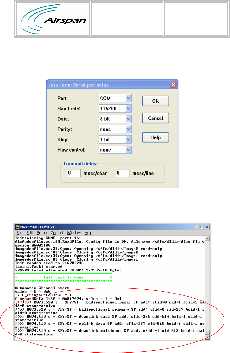
• Connect to the MicroMAX using serial cable
• Use a terminal client application with the following parameters:
• Connect the to electricity (through the SDA)
• Verify that the following lines appear on your serial connection
window(Wait about 1-2 minutes)
L
INK
I
NSTRUCTION
REVISION: A0
---------------------------------------------------------------------------------------
Doc. Link Instruction
Printing Date: 11/05/08 Page 5 of 5
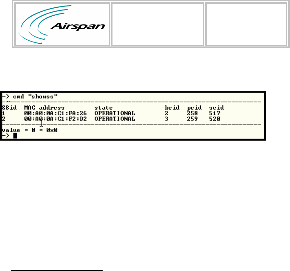
• Through the serial connection type : cmd “showss”
• Verify you have one SS connected and operational
• For broadcasting video through Airspan Networks link please refer to the
link as a normal bridge (layer 2)
Note: Once the system detects a radar signal it will behave according to the
standard and stop transmitting on the channel. A new channel is chosen
and a startup scan is initiated on that channel. A report will be sending on
the Hyper Terminal Application.
Test Mode Commands
• Through the serial connection type:
1. G_DEBUG_DFS_DONT_MOVE=1 //// Do not jump channel
2. G_DEBUG_DFS_DONT_MOVE=0 //// jump channel
3. cmd "setDfsParams av=0" //// Disable availability test
4. cmd "setDfsParams av=1" //// Enable availability test
5. printRf //// Print RF channel
End Document