Airspan Networks H1KD25L Base station of LTE fixed cellular system User Manual

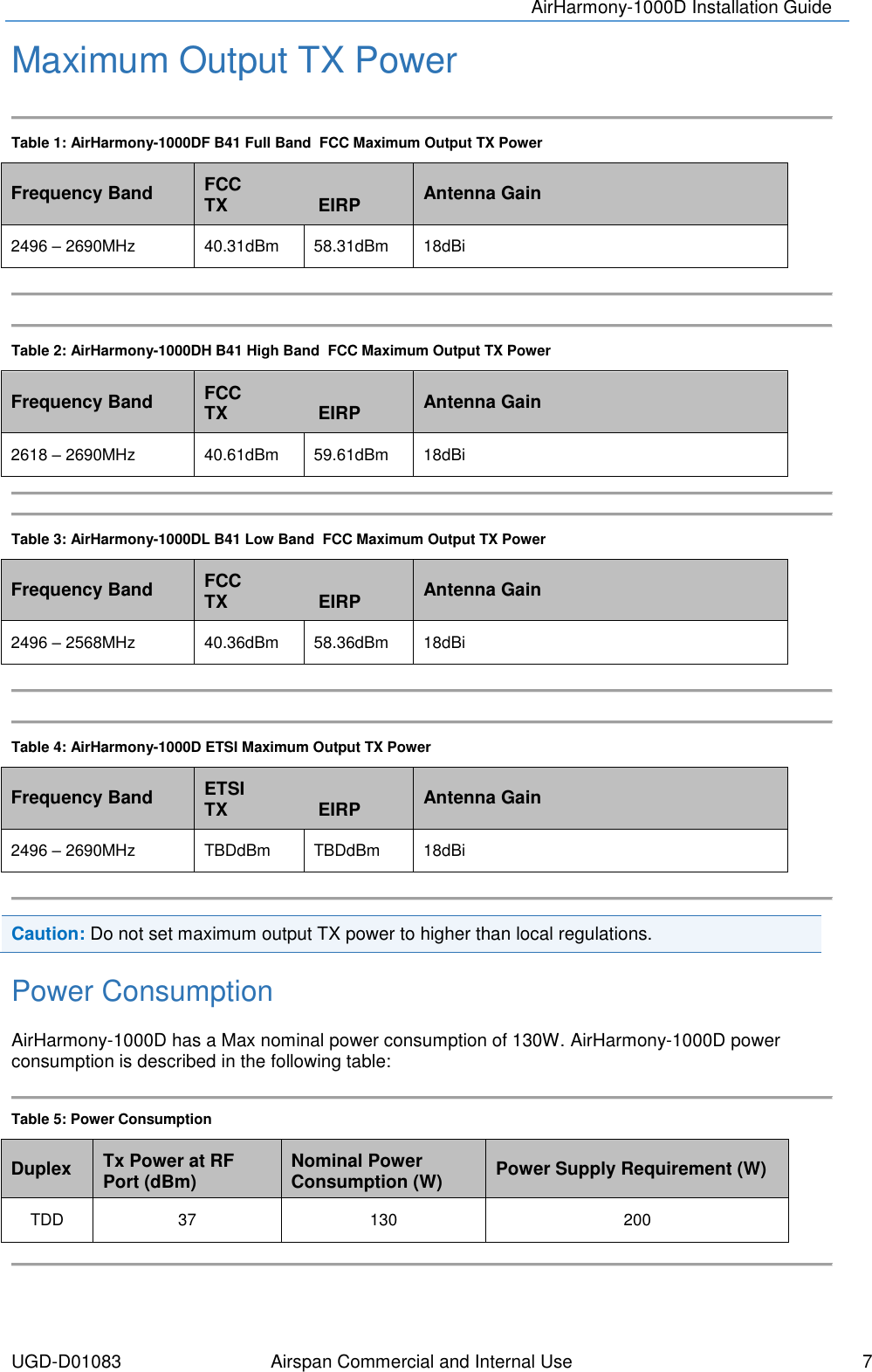
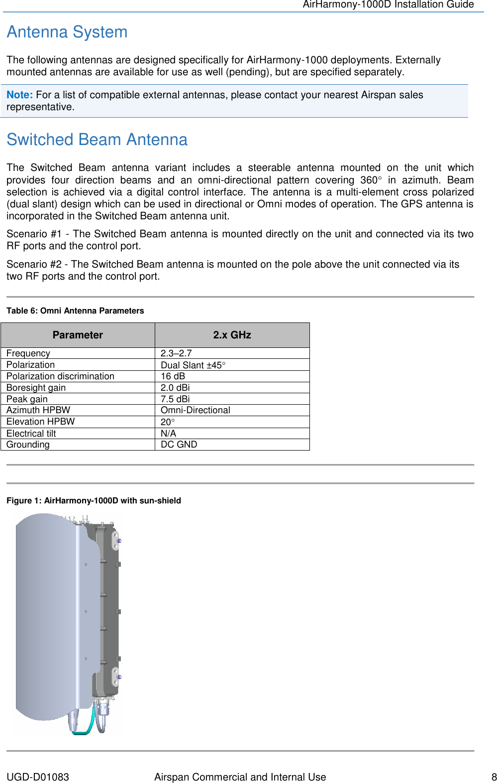
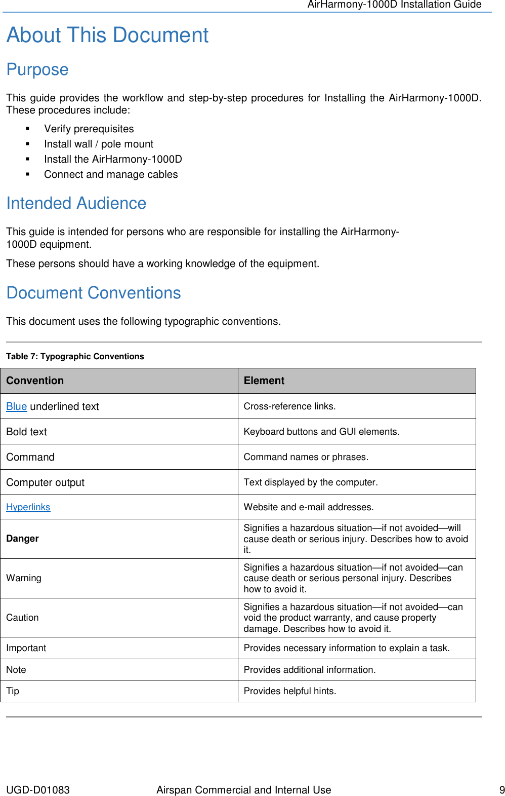
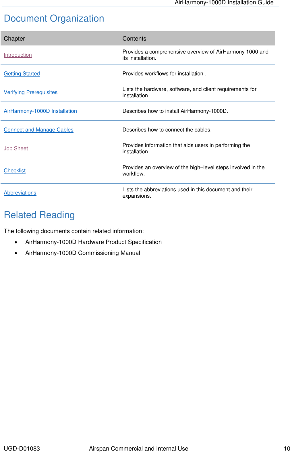
Airspan Networks Inc Base station of LTE fixed cellular system Users Manual

Users Manual

                      AirHarmony-1000D Installation Guide                Part Number: UGD-D01083 System Release: 14.5 Revision: A Published: January 2016
   © Copyright by Airspan Networks Inc., 2016. All rights reserved worldwide. Legal Notices The information contained within this document is proprietary and is subject to all relevant copyright, patent and other laws protecting intellectual  property, as  well as  any specific agreements protecting Airspan Networks  Inc.  rights  in  the  aforesaid information. Neither this document nor the information contained herein may be published, reproduced or disclosed to third parties, in whole or in part, without the express, prior, written permission of Airspan Networks Inc. In addition, any use of this document or the information contained herein for the purposes other than those for which it is disclosed is strictly forbidden. Airspan Networks Inc. reserves the right, without prior notice or liability, to make changes in equipment design or specifications. Information supplied by Airspan Networks Inc. is believed to be accurate and reliable. However, no responsibility is assumed by Airspan Networks Inc. for the use thereof nor for the rights of third parties which may be effected in any way by the use of thereof. Any  representation(s)  in  this  document  concerning  performance  of  Airspan  Networks  Inc.  product(s)  are  for  informational purposes  only  and  are  not  warranties  of  future  performance,  either  expressed  or  implied.  Airspan  Networks  Inc.  standard limited warranty, stated in its sales contract or order confirmation form, is the only warranty offered by Airspan Networks Inc. in relation thereto. This  document  may  contain  flaws,  omissions  or  typesetting  errors;  no  warranty  is  granted  nor  liability  assumed  in  relation thereto  unless  specifically  undertaken  in  Airspan  Networks  Inc.  sales  contract  or  order confirmation.  Information  contained herein is periodically updated and changes will be incorporated into subsequent editions. If you have encountered an error, please notify Airspan Networks Inc. All specifications are subject to change without prior notice. Product performance figures quoted within this document are indicative and for information purposes only.  Acknowledgements   © Intel Corporation    http://www.intel.com/   © Microsoft Corporation     http://www.microsoft.com
UGD-D01083 Airspan Commercial and Internal Use    i  Table of Contents Document Information ............................................................................. 1 Abstract .................................................................................................................. 1 Revision History ..................................................................................................... 1 Warnings and Cautions ........................................................................... 2 Human Exposure to Radio Frequencies ................................................................ 2 Radio Interference ................................................................................................. 2 Modifications .......................................................................................................... 2 General .................................................................................................................. 2 Safety ..................................................................................................................... 2 Warning of Hazardous Voltages ............................................................................ 3 Adherence to European Directive 1999/519/EC .................................................... 3 Warning Symbols ................................................................................................... 3 Service Information ................................................................................................ 3 UL Information ....................................................................................................... 4 Lightning Protection ............................................................................................... 4 DECLARATION OF CONFORMITY ........................................................ 5 GPS Compliance ................................................................................................... 6 Maximum Output TX Power .................................................................... 7 Power Consumption ............................................................................................... 7 Antenna System ..................................................................................................... 8 Switched Beam Antenna ........................................................................................ 8 About This Document ............................................................................. 9 Purpose .................................................................................................................. 9 Intended Audience ................................................................................................. 9 Document Conventions .......................................................................................... 9 Document Organization ....................................................................................... 10 Related Reading .................................................................................................. 10 Customer Care Help Desk .................................................................... 11 Airspan Encourages Comments .......................................................................... 11
AirHarmony-1000D Installation Guide  UGD-D01083 Airspan Commercial and Internal Use    ii  1 Introduction ....................................................................................... 12 1.1 AirHarmony-1000D ........................................................................................ 12 1.1.1 Deployment .................................................................................................. 12 2 Getting Started .................................................................................. 14 2.1 Workflow of Installation ................................................................................. 14 2.2 AirHarmony-1000D Installation Checklist ...................................................... 14 3 Verifying Prerequisites ...................................................................... 15 3.1 Verifying Site Requirements .......................................................................... 15 3.2 Verify Installation Requirements .................................................................... 15 3.2.1 Verify the Tools ............................................................................................ 15 3.2.2 Power Supply ............................................................................................... 15 3.2.3 Verify the Parts and Kits ............................................................................... 16 3.2.4 Physical Dimensions .................................................................................... 19 3.2.5 Environmental .............................................................................................. 19 4 Before Installation of AirHarmony-1000D .......................................... 21 4.1 Connection of GPS Antenna ......................................................................... 21 4.2 Weather-proofing of the Antenna Connections ............................................. 21 5 Installing AirHarmony-1000D ............................................................. 23 5.1 Pole Mount Assembly .................................................................................... 23 5.2 Wall Mount Assembly .................................................................................... 26 5.3 Securing AirHarmony-1000D to the Mounting Plate ...................................... 28 5.4 LED Display .................................................................................................. 29 5.5 Connecting the Ground Cable ....................................................................... 29 6 Cable Connections ............................................................................ 31 6.1 Copper Ethernet Cable Assembly ................................................................. 31 6.1.1 Hardware Requirements .............................................................................. 31 6.1.2 Assembly Instructions .................................................................................. 31 6.2 Fiber Ethernet (SFP) Cable Installation ......................................................... 32 6.2.1 SFP Cable Connection ................................................................................. 32 6.3 Power Cable Preparation .............................................................................. 34 7 Additional Installations (Non-Standard) ............................................. 36 7.1 Connecting RF Jumper Cables to External Antenna ..................................... 36
AirHarmony-1000D Installation Guide  UGD-D01083 Airspan Commercial and Internal Use    iii  A Job Sheet .......................................................................................... 37 B Abbreviations .................................................................................... 38  Figures Figure 1: AirHarmony-1000D with sun-shield ......................................................................................... 8 Figure 2: AirHarmony-1000D ................................................................................................................ 13 Figure 3: Workflow ................................................................................................................................ 14 Figure 4: AirHarmony-1000D Unit, bottom w/o Sun-Shield .................................................................. 18 Figure 5: AirHarmony-1000D Unit, Top, RF ports w/o Sun-Shield ....................................................... 19 Figure 6: Attaching GPS antenna to unit .............................................................................................. 21 Figure 7: Verify connection of RF cable ................................................................................................ 22 Figure 8: Weather-proof the connection ............................................................................................... 22 Figure 9: Pole mounting assembly preparation .................................................................................... 23 Figure 10: Mounting plate on pole ........................................................................................................ 24 Figure 11: Assemble clamp bands (4 required) .................................................................................... 24 Figure 12: Press down locking mechanism .......................................................................................... 24 Figure 13: Tighten clamp bands ........................................................................................................... 25 Figure 14: Pole mounting – exploded view ........................................................................................... 25 Figure 15: Mounted on pole .................................................................................................................. 26 Figure 17: Positioning wall mounting plate ........................................................................................... 27 Figure 18: Wall mounting plate fastened on wall .................................................................................. 27 Figure 19: Lift unit to top of mounting plate........................................................................................... 28 Figure 20: unit engages into slots on the top of mounting plate ........................................................... 28 Figure 21: AirHarmony-1000D unit engaged into the bottom slots ....................................................... 29 Figure 22: Attaching ground cable to AirHarmony-1000D .................................................................... 30 Figure 23: attach ground cable to pole (example) ................................................................................ 30 Figure 25: Ethernet Cable through connector ....................................................................................... 31 Figure 42: LC duplex cable assembly ................................................................................................... 32 Figure 43: Cable connector hook up to the board connector ................................................................ 32 Figure 44: Slide on inner housing ......................................................................................................... 33 Figure 45: Slide over and click .............................................................................................................. 34 Figure 26: Power connection on bottom panel of AirHarmony-1000D ................................................. 34 Figure 27: Power cable assembly ......................................................................................................... 35 Figure 28: Attach Power cable .............................................................................................................. 35 Figure 29: Power cable attached to AirHarmony-1000D ...................................................................... 35 Figure 54: Connecting RF cable ........................................................................................................... 36 Figure 55: Weather-proof the connection ............................................................................................. 36
AirHarmony-1000D Installation Guide  UGD-D01083 Airspan Commercial and Internal Use    iv  Tables Table 1: AirHarmony-1000DF B41 Full Band  FCC Maximum Output TX Power .................................. 7 Table 2: AirHarmony-1000DH B41 High Band  FCC Maximum Output TX Power ................................ 7 Table 3: AirHarmony-1000DL B41 Low Band  FCC Maximum Output TX Power .................................. 7 Table 4: AirHarmony-1000D ETSI Maximum Output TX Power ............................................................. 7 Table 5: Power Consumption .................................................................................................................. 7 Table 6: Omni Antenna Parameters ....................................................................................................... 8 Table 7: Typographic Conventions ......................................................................................................... 9 Table 8. Minimum Hardware Requirements ......................................................................................... 15 Table 9: AirHarmony-1000D Components ............................................................................................ 16 Table 10. AirHarmony-1000D Physical Dimensions ............................................................................. 19 Table 11. AirHarmony 1000 Environment Compliance ......................................................................... 20 Table 12: LED display ........................................................................................................................... 29 Table 10: Cable Hardware .................................................................................................................... 31
AirHarmony 1000D Installation Guide  UGD-D00105 Airspan Commercial and Internal Use    1  Document Information   Abstract This document details procedures for installing the Airspan’s AirHarmony 1000D Micro eNodeB variant.  Revision History Revision Details Date Summary of Changes Rev 0.1 January 2016   Initial document
AirHarmony-1000D Installation Guide  UGD-D01083 Airspan Commercial and Internal Use    2  Warnings and Cautions Human Exposure to Radio Frequencies The AirHarmony-1000D antennas should be installed and operated from a minimum safe distance of:   AirHarmony-1000D with External Antenna: 2.5m   AirHarmony-1000D with Smart Beam Antenna (SBA): 2.5m Radio Interference This AirHarmony-1000D generates, uses, and can radiate radio frequency energy and, if not installed and  used  in  accordance  with  the  instructions,  may  cause  harmful  interference  to  radio communications.  However,  there  is  no  guarantee  that  interference  will  not  occur  in  a  particular installation. If this equipment does cause harmful interference to radio or television reception, which can be determined by turning the equipment on and off, the technician is encouraged to try to correct the interference by performing one or more of the following measures:  Re-orientate or relocate the unit    Increase separation between the units and/or End Device   Connect the equipment to an outlet on a circuit different from that to which the power source is connected Modifications Any changes and modifications to this device that are not expressly approved by Airspan Networks may void the user's authority to operate the equipment. General   Only qualified personnel should be allowed to install, replace, and service the equipment.   The device cannot be sold retail, to the general public or by mail order. It must be sold to operators.   Installation must be controlled.   Installation must be performed by licensed professionals.   Installation requires special training. The AirHarmony-1000D radio and antenna should be installed ONLY by experienced installation professionals who are familiar with local building and safety codes and, wherever applicable, are licensed by the appropriate government regulatory authorities. Failure to do so may void Airspan's product warranty and may expose the end user or the service provider to legal and financial liabilities. Airspan and its resellers or distributors are not liable for injury, damage or violation of regulations associated with the installation of outdoor units or antennas.   The device is to be installed in a Restricted Access Location. Safety  1.  Read this guide and follow all operating and safety instructions. 2.  Keep all product information for future reference. 3.  Static sensitive components inside - do not remove the lid or base: No user serviceable parts inside. 4.  Position the power cord to avoid possible damage; do not overload wall outlets. 5.  Do not place this product on or near a direct heat source, and avoid placing objects on the terminal.
AirHarmony-1000D Installation Guide  UGD-D01083 Airspan Commercial and Internal Use    3  6.  To avoid electrical shock do not install this device during adverse conditions such as rain or inclement weather. 7.  Use only a damp cloth for cleaning. Do not use liquid or aerosol cleaners. Disconnect the power before cleaning. 8.  The units should not be located too near power lines or other electrical power circuits, where it can come into contact with such power lines or circuits. 9.  The radio transceiver must be properly grounded to protect against power surges and accumulated static electricity. It is the user’s responsibility to install this device in accordance with the local electrical codes. 10.  Installation of the AirHarmony-1000D must be contracted to a professional installer.  11.  Disconnect Device. The socket outlet should be easily accessible in case you have to disconnect the device. 12.  When installed in the final configuration, the product must comply with the applicable Safety Standards and regulatory requirements of the country in which it is installed. If necessary, consult with the appropriate regulatory agencies and inspection authorities to ensure compliance. Warning of Hazardous Voltages On AC installations, hazardous voltages exist.  Use caution when verifying or working with AC power.  Remove metal jewellery that could come into contact with AC power. On DC sections, short-circuiting the low voltage, low impedance circuits can cause severe arcing that may result in burns or eye damage.  Remove rings, watches etc. to avoid shorting DC circuits. Note: Airspan products do not contain hazardous substances (as defined in UK Control of Substances Hazardous to Health Regulations 1989 and the Dangerous Substances Regulations 1990).  At the end of any Airspan products life cycle, the customer should consult with Airspan to ensure that the product is disposed of in conformance with the relevant regulatory requirements. Adherence to European Directive 1999/519/EC European Council Recommendation 1999/519/EC details basic restrictions and reference levels on human exposure to electromagnetic fields as advised by the ICNIRP. Adherence to these recommended restrictions and reference levels should provide a high level of protection as regards the established health effects that may result from exposure to electromagnetic fields. Warning Symbols The following symbols may be encountered during installation or troubleshooting. These warning symbols mean danger. Bodily injury may result if you are not aware of the safety hazards involved in working with electrical equipment and radio transmitters. Familiarize yourself with standard safety practices before continuing.   Electro-Magnetic Radiation High Voltage Service Information Refer all repairs to qualified service personnel. Do not modify any part of this device, as this will void the warranty. Disconnect the power to this product and return it for service if the following conditions apply:
AirHarmony-1000D Installation Guide  UGD-D01083 Airspan Commercial and Internal Use    4  a.  The terminal does not function after following the operating instructions outlined in this manual. b.  The product has been dropped or the housing is damaged. Locate the serial number of the terminal and record this on your registration card for future reference. Also record the MAC address, located on the product sticker. UL Information - The equipment must be properly grounded according with NEC and other local safety code requirements. - Reminder to all the BWA system installers: Attention to Section 820-40 of the NEC which provides guidelines for proper grounding and, in particular, specifies that the cable ground shall be connected to the grounding system of the building, as close to the point of cable entry as is practical. - AirHarmony-1000D is designed to operate in environmental conditions complying with IP66 and relevant standards. Lightning Protection WARNING:  The  following  notes  are  general  recommendations  for  the  system.  The  wireless equipment should be installed by a qualified professional installer and must follow local and national codes  for  electrical  grounding  and  safety.  Failure  to  meet  safety  requirements  and/or  use  of  non-standard practices and procedures could result in personal injury and damage to equipment. A direct lightning strike may cause serious damage even if these guidelines are followed. All outdoor wireless equipment is susceptible to lightning damage from a direct hit or induced current from a near strike. Lightning protection and grounding practices in local and national electrical codes serve to minimize equipment damage, service outages, and serious injury. The antennas are to be DC grounded, so surge protection is not required. Reasons for lightning damage are summarized as: - Poorly grounded tower/antenna sites that can conduct high lightning strike energy into equipment. -  Lack  of  properly  installed  lightning  protection  equipment  that  can  cause  equipment  failures  from lightning induced currents. A lighting protection system provides a means by which the energy may enter earth without passing through and damaging parts of a structure. A lightning protection system does not prevent lightning from  striking;  it  provides  a  means  for  controlling  it  and  preventing  damage  by  providing  a  low resistance  path  for  the  discharge  of  energy  to  travel  safely  to  ground.  Improperly  grounded connections are also a source of noise that can cause sensitive equipment to malfunction. A good tower grounding system disperses most of the surge energy from a tower strike away from the building and equipment. To limit the equipment damage due to a lightning strike, the following practices are recommended for the wireless system: -  Provide  direct  grounding  from  the  antenna  mounting  bracket,  the  radio  and  antenna  and  the lightning/surge protectors to the same ground point at the base of the tower or a ground bus on the building. Use the grounding screws on the antenna bracket and the radio and antenna for terminating the ground wires. - The AC wall outlet ground must be connected to the same grounding system as the eNodeB.
AirHarmony-1000D Installation Guide  UGD-D01083 Airspan Commercial and Internal Use    5  DECLARATION OF CONFORMITY European Community, Switzerland, Norway, Iceland, and Liechtenstein  Declaration of Conformity with Regard to the R&TTE Directive 1999/5/EC English:  This  equipment  is  in  compliance  with  the  essential  requirements  and  other  relevant  provisions  of Directive 1999/5/EC.  Deutsch:  Dieses  Gerät  entspricht  den  grundlegenden  Anforderungen  und  den  weiteren  entsprecheneden Vorgaben der Richtlinie 1999/5/EU.   Dansk:  Dette  udstyr  er  i  overensstemmelse  med  de  væsentlige  krav  og  andre  relevante  bestemmelser  i Directiv 1999/5/EF.   Español:  Este equipo cumple con los requisitos esenciales asi como con otras disposiciones de la Directive 1999/5/EC.   Greek:  ΜΕ  ΤΗΝ  ΠΑΡΟΥΣΑ  Airspan  ΔΗΛΩΝΕΙ  ΟΤΙ  Ο  ΕΞΟΠΛΙΣΜΟΣ  ΣΥΜΜΟΡΦΩΝΕΤΑΙ  ΠΡΟΣ  ΤΙΣ ΟΥΣΙΩΔΕΙΣ ΑΠΑΙΤΗΣΕΙΣ ΚΑΙ ΤΙΣ ΛΟΙΠΕΣ ΣΧΕΤΙΚΕΣ ΔΙΑΤΑΞΕΙΣ ΤΗΣ ΟΔΗΓΙΑΣ 1999/5/ΕΚ.   Français:  Cet appareil est  conforme  aux  exigencies  essentialles  et  aux autres  dispositions  pertinantes  de  la Directive 1999/5/EC.   Íslenska:  Þessi búnaður samrýmist lögboðnum kröfum og öðrum ákvæðum tilskipunar 1999/5/ESB.   Italiano:  Questo  apparato  é  conforme  ai  requisiti  essenziali  ed  agli  altri  principi  sanciti  dalla  Direttiva 1999/5/EC.   Nederlands:  Deze  apparatuur  voldoet  aan  de  belangrijkste  eisen  en  andere  voorzieningen  van  richtlijn 1999/5/EC.   Norsk:  Dette  utstyret  er  i  samsvar  med  de  grunnleggende  krav  og  andre  relevante  bestemmelser  i  EU-directiv 1999/5/EC.   Português:  Este equipamento satisfaz os requisitos essenciais e outras provisões da Directiva 1999/5/EC.   Suomalainen:  Tämä  laite  täyttää  direktiivin  1999/5/EY  oleelliset  vaatimukset  ja  on  siinä  asetettujen  muidenkin ehtojen mukainen.   Svenska:  Denna  utrustning  är  i  överensstämmelse  med  de  väsentliga  kraven  och  andra  relevanta bestämmelser i Direktiv 1999/5/EC. Român: Acest echipament este în conformitate cu cerinţele esenţiale şi alte prevederi relevante ale Directivei 1999/5/CE.  The Declaration of Conformity related to this product can be obtained from PLM@Airspan.com.
AirHarmony-1000D Installation Guide  UGD-D01083 Airspan Commercial and Internal Use    6  GPS Compliance The GPS is in compliance with the essential requirements and other relevant provisions of Directive 1999/5/EC." The GPS complies with the following EMC Common Regulatory Testing standards:   EN55022: Radiated and Conducted Emissions   CISPR 22: Class B   EN 50081-1: Generic Emissions Class B   EN 50082-1: Generic Immunity Class B   EN 61000-4-2: Electrostatic Discharge Immunity   EN 61000-4-3: Radiated RF EM Field Immunity Test   EN 61000-4-4: Electrical Fast Transient/Burst Test   EN 61000-4-6: Conducted Immunity   EN 61000-4-8: Magnetic Field Immunity Note: A GPS is recommended for synchronizing between LTE sectors.  Note: An optional GPS Lightning/Surge protector is available from Airspan when installing the GPS antenna in a remote location for lightning prone deployments.
AirHarmony-1000D Installation Guide  UGD-D01083 Airspan Commercial and Internal Use    7  Maximum Output TX Power  Table 1: AirHarmony-1000DF B41 Full Band  FCC Maximum Output TX Power Frequency Band FCC TX                  EIRP Antenna Gain 2496 – 2690MHz 40.31dBm 58.31dBm 18dBi   Table 2: AirHarmony-1000DH B41 High Band  FCC Maximum Output TX Power Frequency Band FCC TX                  EIRP Antenna Gain 2618 – 2690MHz 40.61dBm 59.61dBm 18dBi  Table 3: AirHarmony-1000DL B41 Low Band  FCC Maximum Output TX Power Frequency Band FCC TX                  EIRP Antenna Gain 2496 – 2568MHz 40.36dBm 58.36dBm 18dBi   Table 4: AirHarmony-1000D ETSI Maximum Output TX Power Frequency Band ETSI TX                  EIRP Antenna Gain 2496 – 2690MHz TBDdBm TBDdBm 18dBi  Caution: Do not set maximum output TX power to higher than local regulations. Power Consumption AirHarmony-1000D has a Max nominal power consumption of 130W. AirHarmony-1000D power consumption is described in the following table:  Table 5: Power Consumption Duplex Tx Power at RF Port (dBm) Nominal Power Consumption (W) Power Supply Requirement (W) TDD 37 130 200
AirHarmony-1000D Installation Guide  UGD-D01083 Airspan Commercial and Internal Use    8  Antenna System The following antennas are designed specifically for AirHarmony-1000 deployments. Externally mounted antennas are available for use as well (pending), but are specified separately. Note: For a list of compatible external antennas, please contact your nearest Airspan sales representative. Switched Beam Antenna The  Switched  Beam  antenna  variant  includes  a  steerable  antenna  mounted  on  the  unit  which provides  four  direction  beams  and  an  omni-directional  pattern  covering  360  in  azimuth.  Beam selection is  achieved via a  digital control  interface. The antenna is a  multi-element cross polarized (dual slant) design which can be used in directional or Omni modes of operation. The GPS antenna is incorporated in the Switched Beam antenna unit. Scenario #1 - The Switched Beam antenna is mounted directly on the unit and connected via its two RF ports and the control port. Scenario #2 - The Switched Beam antenna is mounted on the pole above the unit connected via its two RF ports and the control port.  Table 6: Omni Antenna Parameters Parameter 2.x GHz Frequency 2.3–2.7 Polarization Dual Slant ±45 Polarization discrimination 16 dB Boresight gain 2.0 dBi Peak gain 7.5 dBi Azimuth HPBW Omni-Directional Elevation HPBW 20 Electrical tilt N/A Grounding DC GND   Figure 1: AirHarmony-1000D with sun-shield
AirHarmony-1000D Installation Guide  UGD-D01083 Airspan Commercial and Internal Use    9  About This Document Purpose This guide provides the workflow and step-by-step procedures for Installing the AirHarmony-1000D.  These procedures include:   Verify prerequisites   Install wall / pole mount   Install the AirHarmony-1000D   Connect and manage cables Intended Audience This guide is intended for persons who are responsible for installing the AirHarmony-1000D equipment. These persons should have a working knowledge of the equipment. Document Conventions This document uses the following typographic conventions.  Table 7: Typographic Conventions Convention Element Blue underlined text  Cross-reference links. Bold text Keyboard buttons and GUI elements. Command Command names or phrases. Computer output Text displayed by the computer. Hyperlinks Website and e-mail addresses. Danger Signifies a hazardous situation—if not avoided—will cause death or serious injury. Describes how to avoid it. Warning Signifies a hazardous situation—if not avoided—can cause death or serious personal injury. Describes how to avoid it.  Caution Signifies a hazardous situation—if not avoided—can void the product warranty, and cause property damage. Describes how to avoid it. Important Provides necessary information to explain a task. Note Provides additional information. Tip Provides helpful hints.
AirHarmony-1000D Installation Guide  UGD-D01083 Airspan Commercial and Internal Use    10  Document Organization Chapter Contents Introduction Provides a comprehensive overview of AirHarmony 1000 and its installation. Getting Started Provides workflows for installation . Verifying Prerequisites Lists the hardware, software, and client requirements for installation. AirHarmony-1000D Installation Describes how to install AirHarmony-1000D. Connect and Manage Cables Describes how to connect the cables. Job Sheet Provides information that aids users in performing the installation. Checklist Provides an overview of the high–level steps involved in the workflow.  Abbreviations Lists the abbreviations used in this document and their expansions.  Related Reading The following documents contain related information:   AirHarmony-1000D Hardware Product Specification   AirHarmony-1000D Commissioning Manual
AirHarmony-1000D Installation Guide  UGD-D01083 Airspan Commercial and Internal Use    11  Customer Care Help Desk Airspan’s Customer Care Help Desk offers prompt and efficient customer support services. Note: To  avail  Airspan’s  Customer Care Help Desk support,  you must be a registered user and must have a valid support contract. To register, click here and fill the Registration form. To create and update issue logs, send e-mails to Customer Care Help Desk. Once you submit your issue, the system generates a new issue and sends an issue number for your reference. The system uses this issue number to categorize and store e-mails under the appropriate issue. To help Customer Care Help Desk identify your issue, include the issue number and your Customer Care Helpdesk account details in all further communications. Main Operations Airspan Communications Ltd.  Capital Point  33 Bath Road  Slough, Berkshire  SL1 3UF, United Kingdom  Tel: +44-1895-467-100  Worldwide Headquarters Airspan Networks Inc. 777, Yamato Road, Suite 105 Boca Raton, FL 3341-4408, USA Tel: +1 561 893 8670 Airspan Encourages Comments Airspan  welcomes  any  feedback  and  suggestions  that  help  to  improve  the  quality  of  the documentation. Send your feedback to documentfeedback@airspan.com.
AirHarmony-1000D Installation Guide  UGD-D01083 Airspan Commercial and Internal Use    12  1  Introduction This section provides a descriptive overview of the Airspan’s AirHarmony-1000D Micro / Pico eNodeB variant and its place in the Airspan product suite.  1.1 AirHarmony-1000D AirHarmony-1000D is part of Airspan’s carrier-class 4G Micro eNodeB family. AirHarmony-1000D supports 3GPP’s Long Term Evolution (LTE) eNodeB specifications, providing high-speed data and mobility in order to meet the demands of the Broadband Wireless Access market. AirHarmony-1000D employs Software Defined Radio (SDR) technology, together with two transmit and receive paths, antennas and a GPS receiver - all in a highly integrated, physically small and light, All-Outdoor package, targeted to blend seamlessly into the urban environment. This very compact outdoor product minimizes physical footprint, power consumption and operator OPEX. AirHarmony-1000D will support a wide array of frequencies and channel sizes, able to operate in both licensed and unlicensed bands. Frequencies and channel sizes will be added regularly. AirHarmony-1000D implements dual 37 dBm (2 x 5W) transmitters with the availability of several optional integral antennas and external antennas connectivity. AirHarmony-1000D fully supports the standard LTE (Uu/S1/X2) interfaces. All Airspan eNodeB products, including AirHarmony-1000D, are interoperable with a rich portfolio of 3rd party end user devices, including many handsets, indoor UEs, outdoor UEs and USB dongles from several ODMs, using various chipsets. For an updated of interoperability list, please contact your nearest Airspan Sales Representative. Note: For management please refer to the AirHarmony-1000D LTE Commissioning Manual as well as the Netspan User Manual. 1.1.1 Deployment A highly flexible and scalable 4G Base Station, the AirHarmony-1000D is capable of supporting LTE profiles across multiple frequency bands. Note: The following is for illustration only; actual layout may differ as infrastructure is installation-specific.   Note: AirHarmony-1000D must be properly grounded according with NEC and other local safety code requirements.
AirHarmony-1000D Installation Guide  UGD-D01083 Airspan Commercial and Internal Use    13   Figure 2: AirHarmony-1000D   Note: The illustration above displays the GPS connected directly to the top of the unit; there is also a remote GPS antenna option.
AirHarmony-1000D Installation Guide  UGD-D01083 Airspan Commercial and Internal Use    14  2  Getting Started 2.1 Workflow of Installation The Workflow to install the AirHarmony-1000D is shown in the following diagram:   Figure 3: Workflow   Caution: Antennas must be connected and attached before AirHarmony-1000D is powered on. 2.2 AirHarmony-1000D Installation Checklist Plan the installation of the AirHarmony-1000D by using the Installation Checklist, which you can find as a removable job aid in Appendix A for this guide.
AirHarmony-1000D Installation Guide  UGD-D01083 Airspan Commercial and Internal Use    15  3  Verifying Prerequisites Prior to installing the AirHarmony-1000D, verify the required safety, power, tools, parts and components. This chapter includes the hardware, software, and client requirements for installation. Important: Set up requirements for the installation is detailed in the Job Sheet, see Appendix A.  3.1 Verifying Site Requirements To set up the AirHarmony-1000D, an IP connection to a Netspan server is required. 3.2 Verify Installation Requirements 3.2.1 Verify the Tools Note: AirHarmony-1000D variants with front mounted, Sunshield (pending) and Switched Beam (pending) antennas come pre-assembled from the production line.  Table 8. Minimum Hardware Requirements Tool Use Large flat bladed screwdriver  securing the pole straps 10mm or 13/32 inch wrench  for securing flange nuts Large pliers  Tightening cable glands - To fit 15mm  3.2.2 Power Supply AirHarmony-1000D supports direct connection to DC power source (-48V DC):   Operational Voltage Range: -40.5 to -57 VDC   Transient Voltage: +150V (ETR283) AC power feed is also available, using an AC/DC power converter offered by Airspan.
AirHarmony-1000D Installation Guide  UGD-D01083 Airspan Commercial and Internal Use    16  3.2.3 Verify the Parts and Kits The following figures display various AirHarmony-1000D components and accessory kits. Note: Verify order and requirements to ensure the correct unit type is being installed.   Table 9: AirHarmony-1000D Components Parts Description Installation Kit / Part Product Code Images AirHarmony 1000D 2.496 - 2.568 GHz (B41L), Connectorized, AC, Copper BH with PoE out HAR10D-CN-U41L-B00AP  AirHarmony 1000D 2.618 - 2.69 GHz (B41H), Connectorized, AC, Copper BH with PoE out HAR10D-CN-U41H-B00AP  AirHarmony 1000D 2.496 - 2.69 GHz (B38, B41), Connectorized, AC, Copper BH with PoE out HAR10D-CN-U41-B00AP  AirHarmony 1000D universal wall and pole mounting kit HAR10D-U-PMK-2  GPS Antenna with built-in high, interference rejection GPS-ANT-3  AirHarmony GPS Kit (including antenna, bracket, 16m cable and surge protection kit)   GPS-HAR-KIT-1  2.3-2.7GHz Omni-Directional Switched Beam 2-8dBi Dual X-Polar Antenna with GPS SBA-2.X-GPS-1
AirHarmony-1000D Installation Guide  UGD-D01083 Airspan Commercial and Internal Use    17  Parts Description Installation Kit / Part Product Code Images AC/DC Outdoor Power Converter Kit & hardware   Wall & Pole mounting for AC/DC Converter   Mounting bracket for AC/DC converter.   Serratub Maxi Clamp, band 12mm wide + quick adjust lock, 50-215mm pole dia.   Sems Pan Hd M4x10 DIN 7985 with Plain&Spring Washers, St St, A2   AC/DC Converter 48V, 240W, 90-305Vac, IP67, -30/+70C, EN60950-1 SYN-PSU-ODUL-AC-2   DC side cable is pre-connected to the AirHarmony-1000D DC plug. Cable length is 300/1000mm   AC side cable 3 wires (brown, blue & green). Cable length 300mm. should be connected to the AC cable by using the weather-proof cable joiner.  AC cable weather-proof cable joiner - SYN-PWR-JOIN-1 HAR10-ACDC-KIT-ODUL-1  AC Cable, 3x 18AWG per meter, (white, black & green) CBL-AC-3x18AWG-1  Outer Fiber Cables (ASX Optical cables in 8 available lengths)  FIB-FA-10-LC-SM-1 10M  FIB-FA-15-LC-SM-1 15M  FIB-FA-30-LC-SM-1 30M  FIB-FA-50-LC-SM-1 50M  FIB-FA-75-LC-SM-1 75M  FIB-FA-100-LC-SM-1 100M  FIB-FA-150-LC-SM-1 150M  FIB-FA-200-LC-SM-1 200M  Ground cable  (Note that the cable is ordered per meter and the lug is ordered separately. Crimping is done by the user) CBL-GND-1M-1  Grounding Lug Ring Terminal for 6AWG grounding cable. (M6 x 8mm screw) CON-LUG-GND-1
AirHarmony-1000D Installation Guide  UGD-D01083 Airspan Commercial and Internal Use    18  Parts Description Installation Kit / Part Product Code Images DC Power cable v1, 10m Alternative to the AC/DC converter kit. Additional lengths available. PWR-10-MF-1  PVC Insulation tape 20m, Black 19mm width  PVC-INS-TAPE-1  Self-amalgamating waterproof tape 10m, Black 25mm width S-AMAL-WP-TAPE-1  Airspan Recommends: Finisar SFP Transceiver FTLF1318P3BTL 1000BASE-LX Tested and approved by Airspan.  Available from Airspan if required.  AirHarmony-1000D is shown below from the Ethernet termination and RF port end views respectively.  Figure 4: AirHarmony-1000D Unit, bottom w/o Sun-Shield
AirHarmony-1000D Installation Guide  UGD-D01083 Airspan Commercial and Internal Use    19   Figure 5: AirHarmony-1000D Unit, Top, RF ports w/o Sun-Shield   3.2.4 Physical Dimensions AirHarmony-1000D is in an all outdoor enclosure.  Table 10. AirHarmony-1000D Physical Dimensions Variant Dimensions (H x W x D) Comment Connectorized  (with sunshield) 549 x 142 x 203 mm / 21.6 x 5.6 x 8.0 in. The physical dimensions exclude connectors SBA (with sunshield) 770 x 142 x 203 mm / 30.3 x 5.6 x 8.0 in. Weight Main unit (Connectorized) 11 kg (24.25 lb)  Universal mounting bracket (Including pole straps) 925 g (2.04 lb)  Sun-shield 575 g (1.27 lb)  SBA Antenna 1 Kg (2.20 lb) (pending)   3.2.5 Environmental Note: AirHarmony-1000D is not meant to be used in a Marine environment.  AirHarmony 1000 meets the following environmental requirements:   ETSI EN 300-019-1-4 Operational (non-weather protected equipment)   ETSI EN 300-019-1-1 Storage (weather protected, not temperature controlled locations)
AirHarmony-1000D Installation Guide  UGD-D01083 Airspan Commercial and Internal Use    20    ETSI EN 300-019-1-2 Transportation  Table 11. AirHarmony 1000 Environment Compliance Type Details Standard Compliance Operating temperature -40°C to 55°C ETSI 300 019 1-4 Operating humidity 5% - 100% non-condensing ETSI 300 019 1-4 Storage temperature -40°C to 70°C N/A Storage humidity 5% - 100% non-condensing ETSI 300 019 1-4 Rain and dust ingress protection IP66 N/A Operational altitude 70-106 kPa as well as: From -60m to 1800m @ 40C From 1800m to 4000m @ 30C ETSI 300 019 1-4 Solar radiation 1120 W/m2 ETSI 300 019 1-4
AirHarmony-1000D Installation Guide  UGD-D01083 Airspan Commercial and Internal Use    21  4  Before Installation of AirHarmony-1000D Prior to installation of the AirHarmony either on a pole or a wall the GPS antenna should be connected and the all antenna connections should be weather-proofed. 4.1  Connection of GPS Antenna The following defines the connection of the GPS antenna which is installed directly to the top of the unit. 1.  Remove the protective dust cap from the GPS antenna jack prior to mounting on the AirHarmony-1000D. 2.  Align the GPS jack with the plug attached to the top panel on the AirHarmony-1000D. 3.  Attach the GPS antenna to the TNC connector on the unit.  Figure 6: Attaching GPS antenna to unit   Caution: Take care not to over tighten so as not to damage the threads.  Note: It is good practice to weather-proof the antenna connections both the GPS connection and the RF connections. 4.2  Weather-proofing of the Antenna Connections Weather-proofing of all the connections is required. This is done with a layer of self-amalgamating tape followed by an over layer of PVC tape. The weather-proofing is best done at this stage to give easier access to the connections. Note: It is good practice to weather-proof the antenna connections both the GPS connection and the RF connections. The RF connectors on the Front Mount Antenna variant arrive pre-connected. Weather-proofing is best done at this stage to give easier access to the connections. 1.  Verify a secure connection of the RF cable between the antenna and the appropriate RF connection on the top of the unit.
AirHarmony-1000D Installation Guide  UGD-D01083 Airspan Commercial and Internal Use    22   Figure 7: Verify connection of RF cable    Caution: Do not over-tighten the RF connector. RF failures can result when the RF connector is over-tightened.  Figure 8: Weather-proof the connection   2.  Weather-proofing of the connections is mandatory. This is done with a layer of self-amalgamating tape followed by an over layer of PVC tape. Both the self-amalgamating tape and the PVC tape are available from Airspan. 3.  Verify the RF connector is completely weather-proof.
AirHarmony-1000D Installation Guide  UGD-D01083 Airspan Commercial and Internal Use    23  5  Installing AirHarmony-1000D Install the AirHarmony-1000D eNodeB by pole mount or wall mount.  AirHarmony-1000D is mounted on a pole or wall with its pre-installed antenna (front mount or SBA variants (pending)) or in close proximity to its external antenna (connectorized variant). Take care to install the mounting plate the correct way up. This is with the slot openings in the bracket at the top edges as shown below. Caution: Proper local rigging and hoisting practices should be followed when installing the AirHarmony-1000D. 5.1 Pole Mount Assembly The following images show the pole mount assembly. 1.  Prepare the mounting plate by assembling the pole clamps in the provided threaded holes with the provided M8X20 Hex Cap screws.  Figure 9: Pole mounting assembly preparation   2.  Insert the clamp straps through the slots in the mounting plate passing them through the pole clamps.
AirHarmony-1000D Installation Guide  UGD-D01083 Airspan Commercial and Internal Use    24   Figure 10: Mounting plate on pole   3.  Position mounting plate on the pole with slots facing up. 4.  Feed clamp bands through the quick release locking mechanisms and wrap around pole.  Figure 11: Assemble clamp bands (4 required)   5.  Wrap the band to properly fit on the pole. Press down locking mechanism with band excess fed through the mechanism.  Figure 12: Press down locking mechanism   6.  Align and position each of the 4 pole clamps. Tighten the clamp bands with large flat screwdriver in place.
AirHarmony-1000D Installation Guide  UGD-D01083 Airspan Commercial and Internal Use    25   Figure 13: Tighten clamp bands   7.  Mounting plate is installed and ready for AirHarmony-1000D mounting.  Figure 14: Pole mounting – exploded view
AirHarmony-1000D Installation Guide  UGD-D01083 Airspan Commercial and Internal Use    26   Figure 15: Mounted on pole   5.2 Wall Mount Assembly The following images show the wall mount assembly. 1.  Position mounting plate against the wall with slots facing up. Be sure to position the wall mounting plate straight with level mounting to ensure the unit sits evenly.
AirHarmony-1000D Installation Guide  UGD-D01083 Airspan Commercial and Internal Use    27   Figure 16: Positioning wall mounting plate   2.  Mark the wall through the holes on the wall mount at the required height. 3.  Attach the mounting plate to the wall using wall plugs (x4) rated for at least 8-10 Kg per fastener.  Figure 17: Wall mounting plate fastened on wall    Note: Wall plugs (x4) and necessary hardware are not supplied by Airspan and are the responsibility of the installer. Recommended minimum 8mm dia. with appropriate wall plugs according to field conditions.
AirHarmony-1000D Installation Guide  UGD-D01083 Airspan Commercial and Internal Use    28  5.3 Securing AirHarmony-1000D to the Mounting Plate Note: The following procedure shown with the Front-Mount antenna variant as shown below. To mount AirHarmony-1000D to the mounting plate, perform the following: 1.  Loosely fit the flange nuts on the studs protruding from the sides of the unit.  Figure 18: Lift unit to top of mounting plate   2.  Hook the studs into the top slots of the mounting plate.  Figure 19: unit engages into slots on the top of mounting plate   3.  With the studs engaged in the top slots raise the unit slightly until the bottom studs also drop into their respective slots.
AirHarmony-1000D Installation Guide  UGD-D01083 Airspan Commercial and Internal Use    29   Figure 20: AirHarmony-1000D unit engaged into the bottom slots   4.  Tighten the flange nuts (4 places) to the required degree of down-tilt. 5.  Check and tighten all flange nuts. 5.4 LED Display A single tri-color LED (Green/Red/Orange) appears at the bottom of the unit, providing unit status indication. When powering up refer to the following table for indication of current status:  Table 12: LED display Name Color Status Description Powering Up Orange On Continuously Till the SW starts loading Software loading Green Blinking (3Hz) While SW is loading Normal Operation Green On Continuously Normal operation (no alarm) Major Alarm Red Blinking (3Hz) Service not affected Critical Alarm or Sector OOS Red On Continuously   5.5 Connecting the Ground Cable Connect the ground cable after attaching the grounding lug (optionally supplied by Airspan – CBL-GND-1M-1 and CON-LUG-GND-1) to the M6 threaded connection on the bottom of the main body casting. Note: Cutting the Ground cable to the required length and crimping the grounding lug is performed by the Installer.  Note: The ground cable is available per meter. The lug can also be used for securing the ground cable to the other side.  Note: The ground surface is bare metal and needs no preparation.
AirHarmony-1000D Installation Guide  UGD-D01083 Airspan Commercial and Internal Use    30  Note: Prior to insertion apply No-Ox or other approved anti-oxidation agent. This ground cable should be connected to a protection ground bar or clamped directly to a steel structure. A direct earth ground connection is required for the surge protection devices inside the AirHarmony-1000D to be effective. 1.  Remove grounding screw and slip the ring terminal end of the ground cable onto the screw prior to re-setting into the threaded hole.  Figure 21: Attaching ground cable to AirHarmony-1000D   2.  Connect the ground cable to the protection ground bar using suitable crimp lugs.  Alternatively use a clamp to bond the ground cable to the mounting pole or to the tower structure.  Figure 22: attach ground cable to pole (example)   Note: Above drawing is for illustration only – use locally approved method for grounding.  Note: For wood pole installations, a 5/8" x 8' ground rod should be installed immediately adjacent to the wood pole and the #6 AWG stranded conductor extended down to the ground rod and connected using and approved method (Exothermic or split bolt).  Note: When installing a protection ground take care to use suitable metal combinations to avoid or minimize galvanic corrosion.
AirHarmony-1000D Installation Guide  UGD-D01083 Airspan Commercial and Internal Use    31  6  Cable Connections Hazardous voltage!  Before working, ensure that the power is removed from the power connection cables.  When the system is powered on, do not touch the power terminals. 6.1 Copper Ethernet Cable Assembly The following demonstrates the recommended assembly instructions, hardware and tool requirements for the proper Ethernet cable assembly of the Ethernet Category 5e (enhanced) (CAT5e) cable used by Airspan products.  The Ethernet cable is connected using a standard RJ45 connector protected by a harsh environment protective casing. 6.1.1  Hardware Requirements The following are the cable and connectors available from Airspan.  Table 13: Cable Hardware Airspan Part Number Description  CAT5e-STP-305M-R CAT5e Ethernet Cable, 305M (1000ft), STP, Reel RJ45-ETH-SHLD-CONN RJ45 Ethernet Connector, Shielded  6.1.2  Assembly Instructions The Copper Ethernet cable is connected to the AirHarmony-1000 using a Gland connector assembled on the bottom panel of the unit. 1.  Remove the Gland connector by unscrewing the body from the AirHarmony-1000, using the (supplied) Gland wrench. 2.  Pass the prepared Ethernet cable through the tail nut, gland seal, body and front seal of the connector casing as shown below. Do not tighten the tail nut.  Figure 23: Ethernet Cable through connector
AirHarmony-1000D Installation Guide  UGD-D01083 Airspan Commercial and Internal Use    32  3.  Seat the RJ45 connector plug securely into the body cavity of the AirHarmony-4000 4.  Tighten the Gland body into to the threaded hole on the bottom of the AirHarmony-4000.  5.  Tighten the tail nut on to the body using the included Gland wrench, forcing the seal compress around the cable. 6.  Once the connector is properly installed, the cable should be positioned and secured to minimize stress on the cable. 6.2 Fiber Ethernet (SFP) Cable Installation The Fiber Ethernet Small form-factor pluggable transceiver (SFP) must be connected to the AirHarmony -1000D using an outdoor fiber cable. The optical connection enables a one-hand installation of the connector. This enables the users to easily remove and replace the SFP transceiver module which eliminates the need to open the unit and expose its contents to hazardous weather conditions. Note: Airspan recommends using the Finisar - FTLF1318P3BTL 1000BASE-LX which has been tested and approved by Airspan. Available from Airspan if required. The Outdoor fiber cable is available in 8 different lengths from 10m to 200m. Note: Airspan recommends to test the fibers prior to installation (using FOA’s standard testing industry standards).  Note: Airspan recommends to clean the fibers according to standard procedure (using FOA’s cleaning guidance). 6.2.1 SFP Cable Connection  Figure 24: LC duplex cable assembly   1.  Remove the protective dust cap from the connector housing assembled on the unit. 2.  Line up the SFP transceiver module with the port and slide it into the port. 3.  Connect the cable connector onto the board connector.  Figure 25: Cable connector hook up to the board connector
AirHarmony-1000D Installation Guide  UGD-D01083 Airspan Commercial and Internal Use    33    4.  Verify that the locking latch on the cable connector is engaged on the board connector. 5.  Slide the inner housing and ground shield (if present) over the cable and over the molding.  Figure 26: Slide on inner housing   Note: Check that there no space between the inner housing and mounting flange. Check and remove any debris that might interfere with the connection.  6.  Slide the outer shell over the inner housing and turn the outer bayonet shell 1/4 turn clockwise, until it clicks into place.
AirHarmony-1000D Installation Guide  UGD-D01083 Airspan Commercial and Internal Use    34   Figure 27: Slide over and click   Note: The shell should be hand tightened only. Do NOT use tools to tighten the shell.  7.  Once the connector is properly installed, the cable should be positioned and secured to minimize stress on the cable and connector. 6.3 Power Cable Preparation The Power cable is connected to the AirHarmony-1000D using a Gland connector assembled on the bottom panel of the unit. 1.  Remove the Gland connector by unscrewing the body from the AirHarmony-1000D, using the Gland wrench. 2.  Pass the pre-assembled connector through the tail nut, gland seal, body and rubber seal of the connector casing as shown below. Do not tighten the tail nut. Note The connector is attached inside the weather protected area of the enclosure and is not subjected to water/moisture therefore the use of die-electric gels is not required.  3.  Connect the DC power cable connector to the female connector outlet inside the unit.  Figure 28: Power connection on bottom panel of AirHarmony-1000D    4.  Screw the gland connector plug securely into the body cavity of the unit using the provided Gland wrench. 5.  Tighten the tail nut on to the body forcing the seal to compress around the power cable using the (provided) Gland wrench.
AirHarmony-1000D Installation Guide  UGD-D01083 Airspan Commercial and Internal Use    35   Figure 29: Power cable assembly   Caution: Do not over tighten the gland connector or the tail nut. The gland nut should be tightened to a torque of no more than 3.3 Nm (2.43 lb-ft) max.   Note: When securing the cable verify there is no tension on the connector so that it is easy to disconnect and re-connect for future maintenance actions.    Figure 30: Attach Power cable    Caution: The internal plastic parts of the mating connector are keyed. Take care to align these by visual inspection or by gently rotating the connector body until the key way sections align and the pins go in before tightening.   Figure 31: Power cable attached to AirHarmony-1000D
AirHarmony-1000D Installation Guide  UGD-D01083 Airspan Commercial and Internal Use    36  7  Additional Installations (Non-Standard) 7.1 Connecting RF Jumper Cables to External Antenna Note: Variants utilizing remotely attached antennas are factory pre-assembled with a sunshield.  For installation of a remotely mounted antenna follow the antenna manufacturer’s instructions and connect the antenna to the AirHarmony-1000D using the appropriate cables. (Weather-proofed N-type Heliax RF cables (ordered separately). 1.  Attach, connect and secure the RF cable between the external antenna and the appropriate RF connection on the top of the unit.  Figure 32: Connecting RF cable   Caution: Do not over-tighten the RF connector. RF failures can result when the RF connector is over-tightened.  Figure 33: Weather-proof the connection    2.  Weather-proofing of the RF N type connections is recommended. This is done with a layer of self-amalgamating tape followed by an over layer of PVC tape. Verify the RF connector is completely weather-sealed.
AirHarmony-1000D Installation Guide  UGD-D01083 Airspan Commercial and Internal Use    37  A  Job Sheet This job sheet enables the users to keep track of their installation. It covers all the prerequisites required for accomplishing the AirHarmony-1000D installation.   Site Requirements  o  Pole or wall for installation identified o  Position on pole or wall identified o  Pole access restrictions (highway regulations, other services on pole, power pole) o  Method of reaching pole positions (ladders, Elevated work platform) o  AC main fuse block available for AC/DC converter (where needed) o  Configuration programming details known o  Point of connection for Ethernet (if applicable) o  All equipment items available at the installation site o  Main AirHarmony-1000D unit o  Mounting bracket and pole clamps o  AC/DC converter o  GPS Antenna o  Self-amalgamating tape o  Black PVC tape o  Weather-proofing of the connections with a layer of self-amalgamating tape followed by an over layer of PVC tape. o  SFP cable assembly Tool Requirements (For further information, see Verify the Tools.) o  Large flat screw driver for pole clamps o  Small flat blade screw driver (insulated shaft recommended) o  Medium Philips head screw driver o  13mm wrench or small pipe wrench o  10mm wrench for unit mounting flange nuts o  Knife o  pliers o  Small side cutters o  Tweezers (or fine blade long nose pliers) o  Wire strippers o  Tilt-meter Required Ancillary Equipment o  Laptop PC for initial configuration o  cable for temporary connection of the lap top
AirHarmony-1000D Installation Guide  UGD-D01083 Airspan Commercial and Internal Use    38  B  Abbreviations Term Expansion 3GPP 3rd Generation Partnership Project, responsible for LTE ABS Almost Blank Subframe ACS Adjacent Channel Selectivity is a measurement of a receiver's ability to process a desired signal while rejecting a strong signal in an adjacent frequency channel. ACS is defined as the ratio of the receiver filter attenuation on the assigned channel frequency to the receiver filter attenuation on the adjacent channel frequency AWGN Additive White Gaussian Noise is a channel model in which the only impairment to communication is a linear addition of white noise with a constant spectral density and a Gaussian distribution of amplitude. BER Bit Error Rate CN Core Network CP Cyclic Prefix CTC Convolution Turbo Code is a high-performance forward error correction (FEC) code dB Decibel. A logarithmic unit used to describe a ratio (such as power ratio in radio telecommunications) dBm An abbreviation for the power ratio in decibels (dB) of the measured power referenced to one milliwatt (mW). It is used as a convenient measure of absolute power because of its capability to express both very large and very small values in a short form eNodeB Evolved Node B, is the element in E-UTRAN of LTE ESP Encapsulating Security Payloads (ESP) provide confidentiality, data-origin authentication, connectionless integrity, an anti-replay service (a form of partial sequence integrity), and limited traffic-flow confidentiality E-UTRAN Evolved UMTS Terrestrial Radio Access Network, is the air interface of 3GPP's Long Term Evolution EVM/RCE The Error Vector Magnitude or EVM (sometimes also called Receive Constellation Error or RCE) is a measure used to quantify the performance of a digital radio transmitter or receiver. It is measured in dB or percentage (%) – the lower the better FDD Frequency-Division Duplexing. A transceiver mode where the transmitter and receiver operate at different carrier frequencies GNSS Global Navigation Satellite System is a term used to describe a satellite navigation system with global coverage. There are currently two fully operational GNSSs – the US GPS and the Russian GLONASS. GTP-U GPRS Tunneling Protocol for User data is a relatively simple IP based tunneling protocol which permits many tunnels between each set of end points HPBW Half Power BandWidth is the angular separation in an antenna, in which the magnitude of the radiation pattern decreases by 50% (or -3 dB) from the peak of the main beam ICS In-channel selectivity is a measure of the receiver’s ability to receive a wanted signal at its assigned Resource Block locations in the presence of an interfering signal IPSec Internet Protocol Security is a protocol suite for securing Internet Protocol (IP) communications by authenticating and encrypting each IP packet of a communication session
AirHarmony-1000D Installation Guide  UGD-D01083 Airspan Commercial and Internal Use    39  LED Light Emitting Diode LTE Long Term Evolution MAC Medium Access Controller – responsible for several functions such Error Correction, Packet (De)Multiplexing, etc… MBSFN Multicast-Broadcast Single Frequency Network is an LTE feature designed to deliver services such as Mobile TV using the LTE infrastructure, and is expected to be a competitor to DVB-H-based TV broadcast MCS Modulation and Coding Scheme  MME Mobility Management Entity is the key control-node for the LTE access-network. It is responsible, among other things for idle mode UE tracking and paging procedure including retransmissions MTBF Mean Time Between Failures OFDMA Orthogonal Frequency-Division Multiple Access (OFDMA) is a multi-user version of OFDM digital modulation scheme, used for eNodeB transmissions to UEs PDCP Packet Data Convergence Protocol. A Sub-Layer in LTE responsible for IP Header (De)Compression, etc… PDU Protocol Data Unit PTP Precision Time Protocol is used to synchronize clocks throughout a network. In this document, PTP is referring to IEEE1588-2008 protocol RB Resource Block RLC Radio Link Control. A Sub-Layer in LTE responsible for Ack/Nack, error correction, packet reordering, etc… ROHS Restriction Of Hazardous Substances RRM Radio Resource Management is used to cover all functions that are related to the assignment and sharing of radio resources among UEs S-GW Serving Gateway. A Core entity in the LTE EPC architecture responsible for routing and forwarding user data packets, while also acting as the mobility anchor for the user plane during inter-eNodeB handovers and as the anchor for mobility between LTE and other 3GPP technologies SBA Switched Beam Antenna SC-FDMA Single-Carrier FDMA is a frequency-division multiple access scheme, dealing with the assignment of multiple users to a shared communication resource. Used in LTE for UE transmissions to the eNodeB SCTP Stream Control Transmission Protocol is a reliable transport layer protocol, ensuring in-sequence transport of messages with congestion control like TCP SDR Software Defined Radio WEEE Waste Electrical and Electronic Equipment

Navigation menu