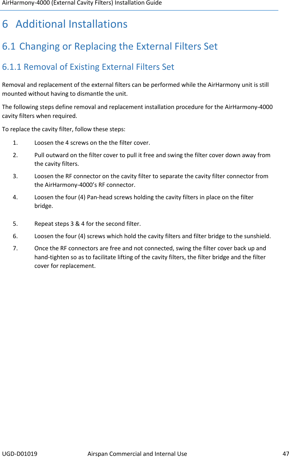
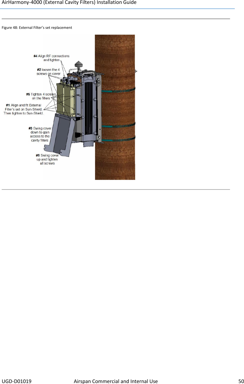
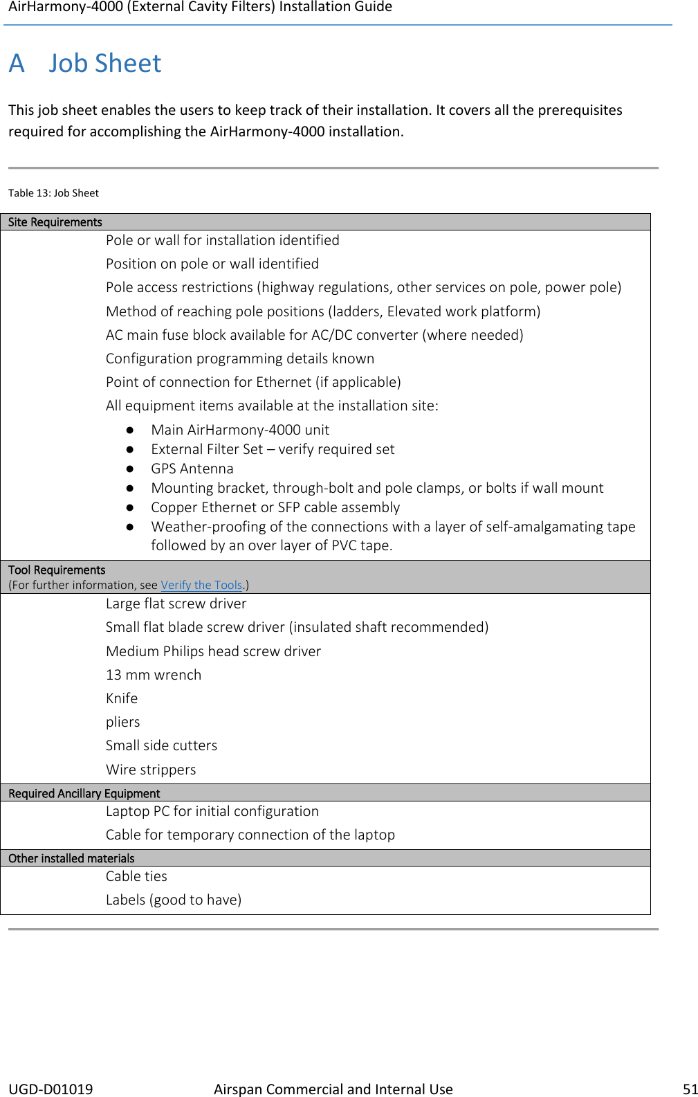
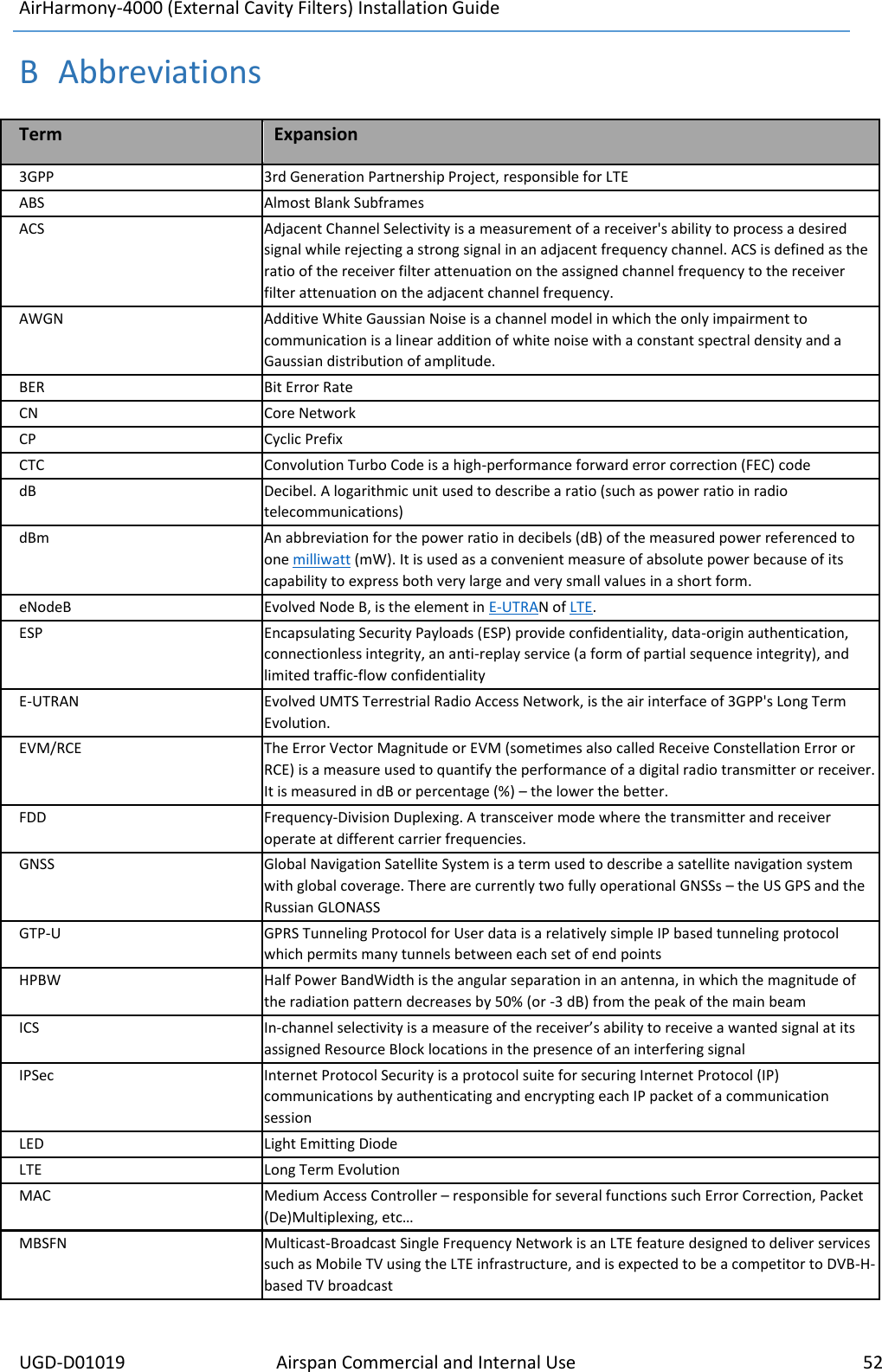
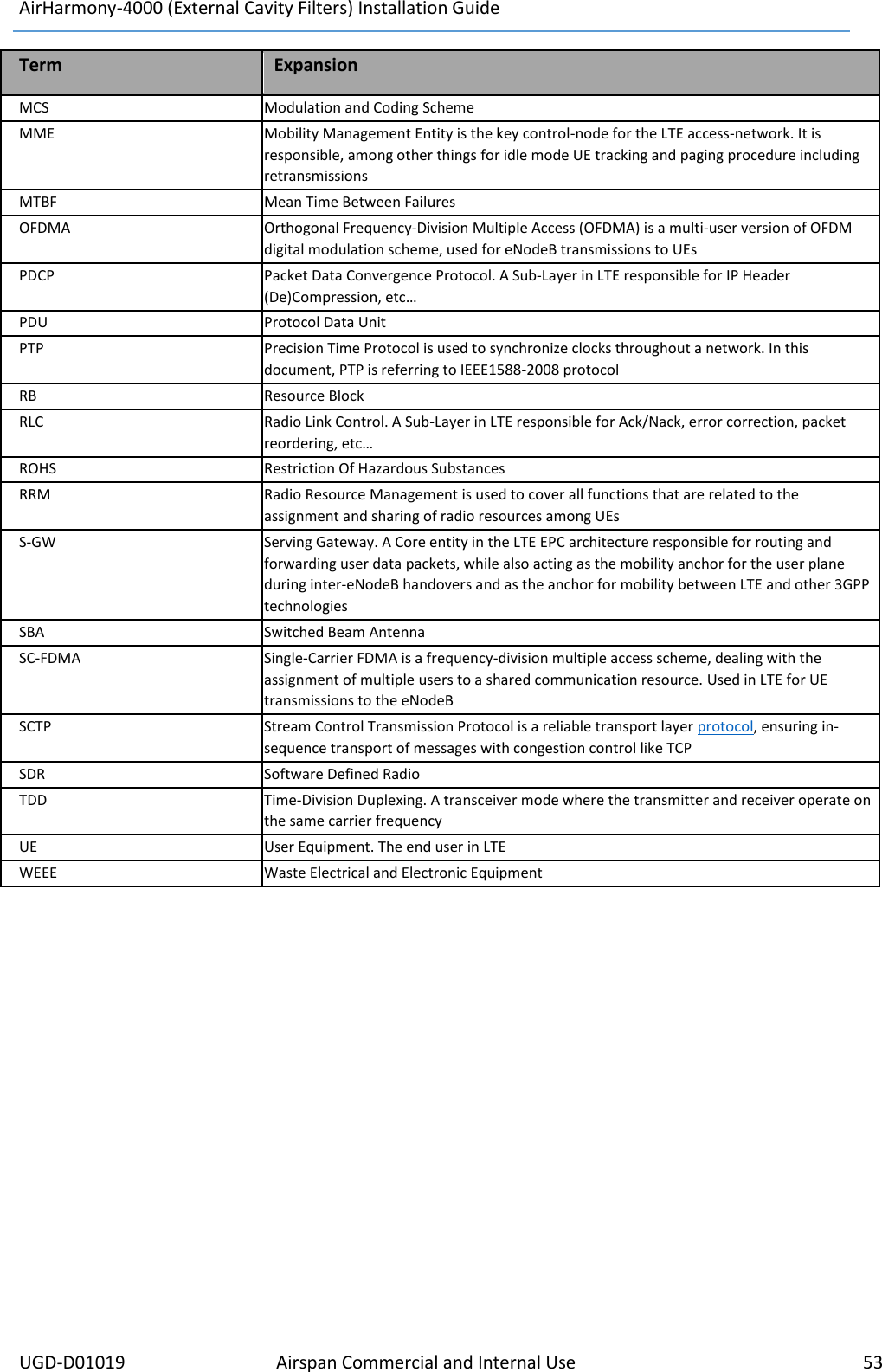
Airspan Networks H4K25 Base station of LTE fixed cellular system User Manual AirHarmony 4000 EXT Installation Guide
Airspan Networks Inc Base station of LTE fixed cellular system AirHarmony 4000 EXT Installation Guide
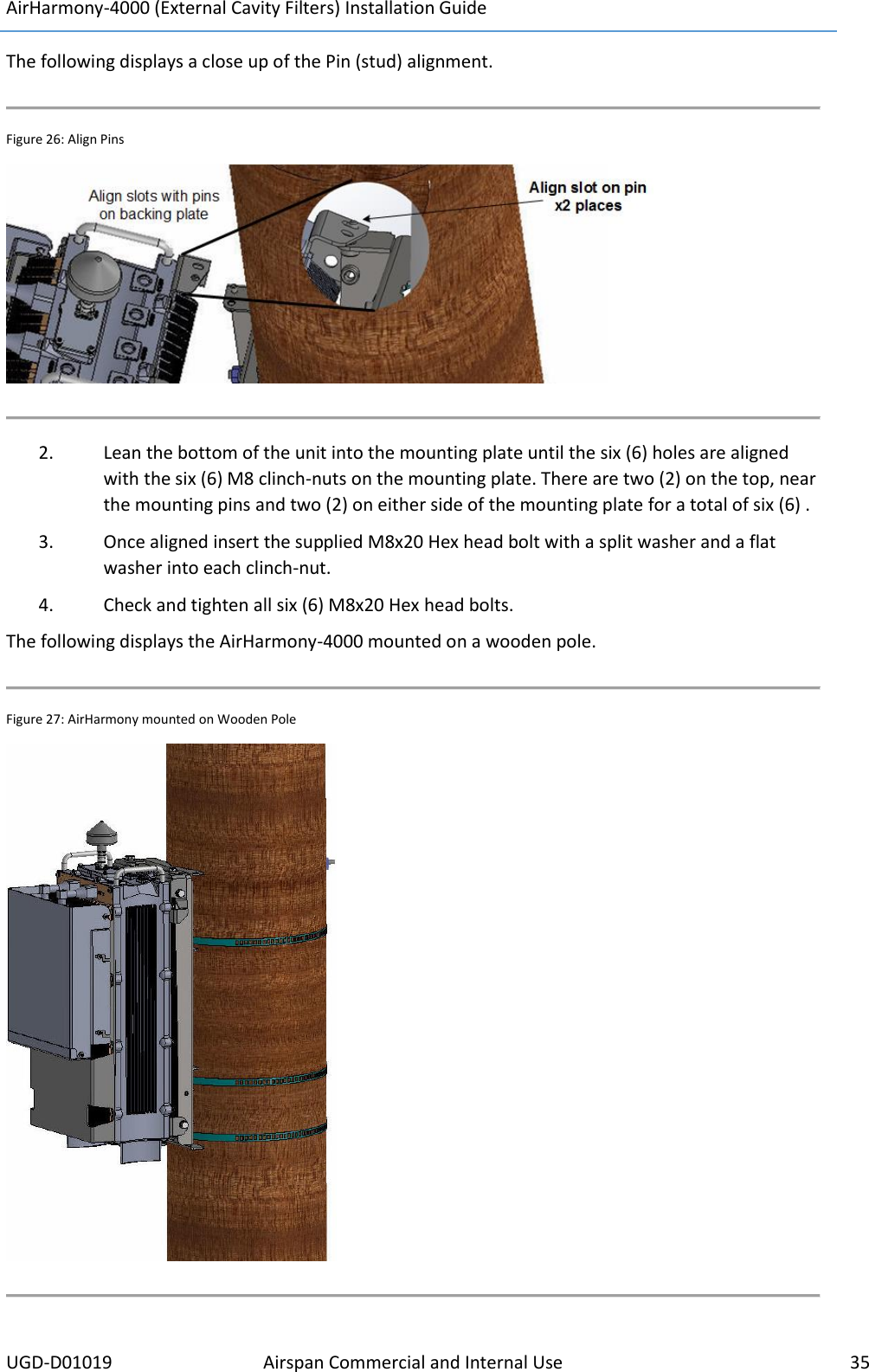
UserManual.wiki
>
Airspan Networks
>
H4K25 User Manual
Users Manual
Navigation menu
Upload a User Manual
Namespaces
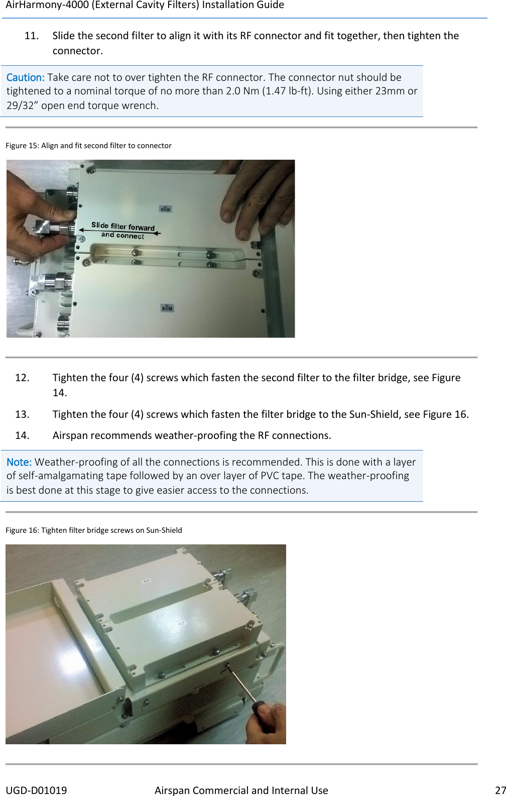
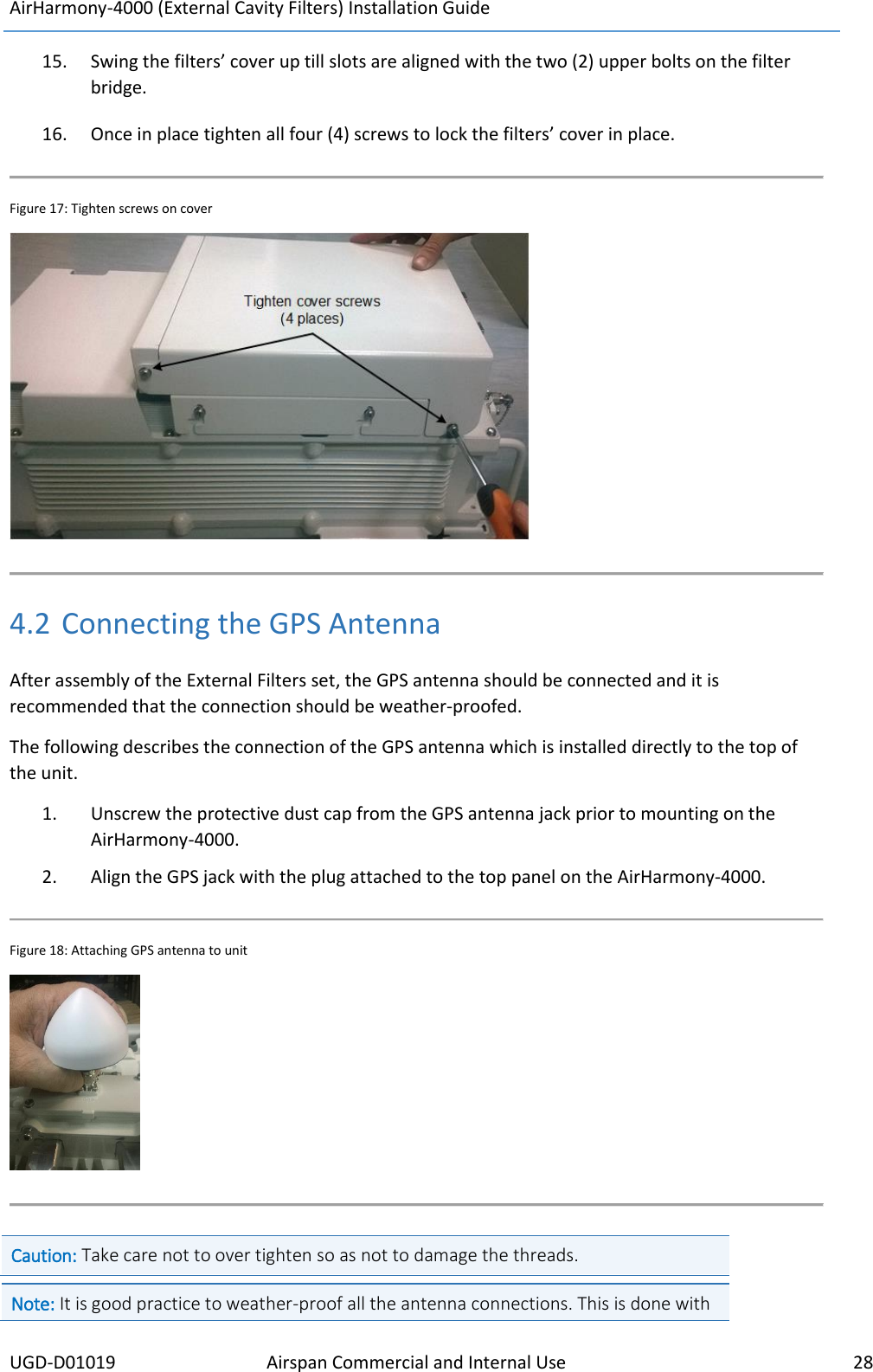
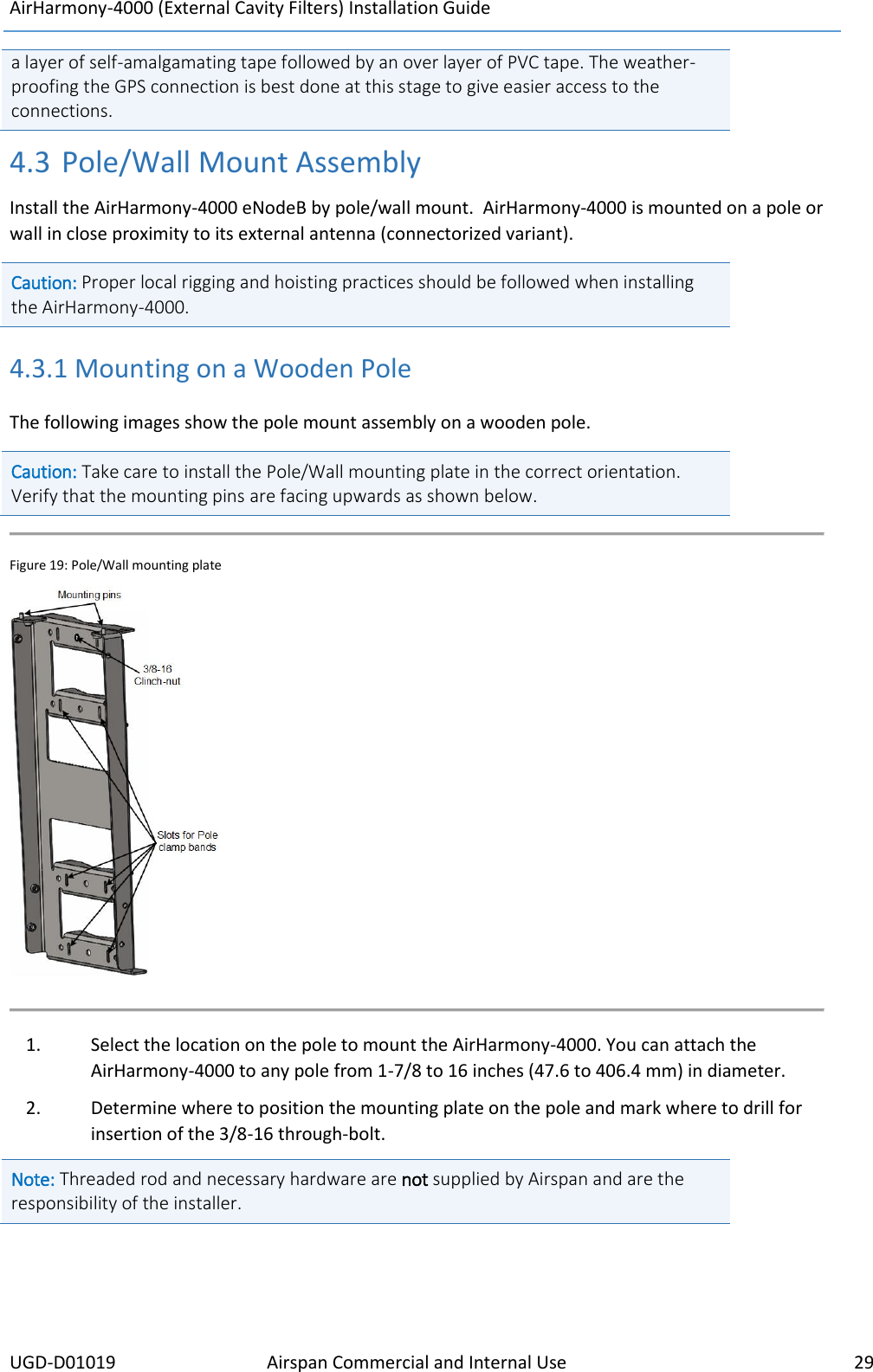
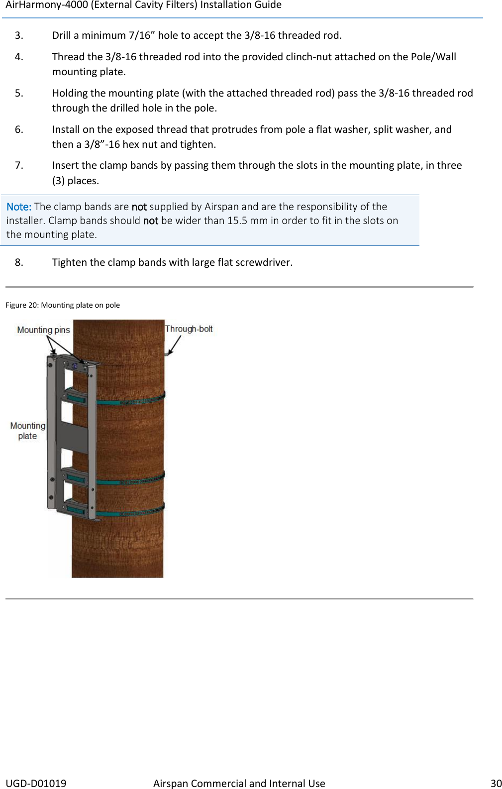
Wiki Guide
HTML
PDF
Info
Views
User Manual
Discussion / Help
Navigation