Airspan Networks MARCONI Wireless Local Loop System User Manual Ch 00 u
Airspan Networks Inc Wireless Local Loop System Ch 00 u
Version 20

WipLL
WipLLWipLL
WipLL
Wireless IP-Based Local Loop System
Release 2.0
WipLL System Description
MCIL-WIPLL-SDN_R2_00

This product is marked with a CE Mark (see below). This mark has been affixed to demonstrate full product
compliance with the following European directives:
a) Directive 73/23/EEC - Council Directive of 19/02/1973 on the harmonization of the laws of Member States
relating to electrical equipment designed for use within certain voltage limits.
b) Directive 89/336/EEC - Council Directive of 3/05/1989 on the approximation of laws of the Member States
relating to Electro-Magnetic Compatibility (EMC).
Issue Date: 2-Apr-01
Revision Record: WipLL System Description
Pub. Rev. Date Update Description
1.2 Nov-00 First edition and printing. Author: MCIL
1.4 Mar-01 WipLL Release 1.4 Issue 02
2.0 Apr-01 WipLL Release 2.0 Issue 01
Publication No. MCIL-WIPLL-SDN_R2_00
Copyright by MARCONI COMMUNICATIONS LTD, 2001. All rights reserved worldwide.
The information contained in this document is proprietary and is subject to all relevant copyright, patent and other
laws protecting intellectual property, as well as any specific agreement protecting MARCONI COMMUNICATIONS
LTD. rights in the aforesaid information. Neither this document nor the information contained herein may be
published, reproduced or disclosed to third parties, in whole or in part, without the express, prior, written
permission of MARCONI COMMUNICATIONS LTD. In addition, any use of this document or the information
contained herein for any purposes other than those for which it was disclosed is strictly forbidden.
MARCONI COMMUNICATIONS LTD. reserves the right, without prior notice or liability, to make changes in
equipment design or specifications.
Information supplied by MARCONI COMMUNICATIONS LTD. is believed to be accurate and reliable. However, no
responsibility is assumed by MARCONI COMMUNICATIONS LTD. for the use thereof nor for the rights of third
parties which may be effected in any way by the use thereof.
Any representation(s) in this document concerning performance of MARCONI COMMUNICATIONS LTD.
product(s) are for informational purposes only and are not warranties of future performance, either express or
implied. MARCONI COMMUNICATIONS LTD. standard limited warranty, stated in its sales contract or order
confirmation form, is the only warranty offered by MARCONI COMMUNICATIONS LTD. in relation thereto.
This document may contain flaws, omissions or typesetting errors; no warranty is granted nor liability assumed in
relation thereto unless specifically undertaken in MARCONI COMMUNICATIONS LTD. sales contract or order
confirmation. Information contained herein is periodically updated and changes will be incorporated into
subsequent editions. If you have encountered an error, please notify MARCONI COMMUNICATIONS LTD. All
specifications are subject to change without prior notice.

QUESTIONS / COMMENTS
If you have questions or comments about this publication, please
e-mail to documentation@marconi.com
Name Company
Tel/Fax/e-mail:
Publication Name: Catalogue No.
My question/comment is:
Thank you.
Marconi Communications Ltd
Marketing Department
This page intentionally left blank

Contents
MCIL-WIPLL-SDN_R2_00 Marconi Communications Ltd. i
Contents
1 GENERAL OVERVIEW............................................................................ 1-1
1.1. Components of the System........................................................... 1-4
1.1.1. The Subscriber Site ........................................................... 1-5
1.1.2. Base Station Components ................................................. 1-6
1.1.3. Coverage........................................................................... 1-7
1.2. Management, and Commissioning ................................................ 1-9
1.2.1. WipManage ..................................................................... 1-10
1.2.2. WipConfig........................................................................ 1-10
2 MAIN FEATURES, PROTOCOL AND QoS.............................................. 2-1
2.1. Features........................................................................................ 2-1
2.1.1. User Perspective ............................................................... 2-1
2.1.2. Operator Perspective......................................................... 2-2
2.1.3. Capacity ............................................................................ 2-2
2.1.4. QoS ............................................................................... 2-2
2.1.5. Configuration ..................................................................... 2-3
2.1.6. Installation and Commissioning ......................................... 2-3
2.1.7. Security ............................................................................. 2-3
2.1.8. MAC Protocol .................................................................... 2-3
2.1.9. Radio Communications...................................................... 2-4
2.1.10. Management...................................................................... 2-5
2.1.10.1. Network Management Systems (NMS) ............ 2-5
2.1.11. System Parameters ........................................................... 2-5
2.1.12. RF ............................................................................... 2-5
2.1.13. Network ............................................................................. 2-6
2.1.14. Application......................................................................... 2-6

WipLL System Description
ii Marconi Communications Ltd. MCIL-WIPLL-SDN_R2_00
2.2. PPMA Protocol.............................................................................. 2-6
2.2.1. What is PPMA? ................................................................. 2-7
2.2.1.1. Concept ............................................................. 2-7
2.2.1.2. Slotted Aloha Process........................................ 2-7
2.2.1.3. Packet Transmission.......................................... 2-8
2.2.1.4. Polling Sequence ............................................... 2-8
2.3. Security......................................................................................... 2-9
2.3.1. Login Mechanism............................................................... 2-9
2.4. QoS............................................................................................... 2-9
2.5. Echo Management...................................................................... 2-10
3 APPLICATIONS AND SERVICES............................................................ 3-1
3.1. Applications................................................................................... 3-1
3.1.1. Fixed Cellular Access System............................................ 3-1
3.1.2. Connecting the Base Station to the Network Backbone..... 3-3
3.1.3. Remote Base Station Backhaul ......................................... 3-4
3.1.3.1. Indoor Coverage ................................................ 3-5
3.2. Services ........................................................................................ 3-7
3.2.1. Broadband Data Access .................................................... 3-7
3.2.2. High Speed Internet Access .............................................. 3-7
3.2.3. Private Networks ............................................................... 3-8
3.2.4. Remote Access ................................................................. 3-9
3.2.5. Video Over IP .................................................................... 3-9
4 BSR.......................................................................................................... 4-1
4.1. Base Station Radio ....................................................................... 4-1
4.1.1. BSR Default Accessories................................................... 4-2
4.2. Network Management ................................................................... 4-3
4.2.1. Capabilities ........................................................................ 4-3
4.2.2. Physical Interfaces ............................................................ 4-4

Contents
MCIL-WIPLL-SDN_R2_00 Marconi Communications Ltd. iii
4.2.3. Communication Interfaces................................................. 4-5
4.2.4. Features and Protocols...................................................... 4-6
4.2.4.1. Features............................................................. 4-6
4.2.4.2. Protocols............................................................ 4-6
4.2.5. Unsynchronized vs Synchronized Operation.................... 4-10
5 BSDU ....................................................................................................... 5-1
5.1. Base Station Distribution Unit........................................................ 5-1
5.2. Network Management ................................................................... 5-2
5.2.1. Management Information Base.......................................... 5-2
5.2.2. Capabilities ........................................................................ 5-2
5.3. Physical Interfaces........................................................................ 5-2
5.3.1. Connectors ........................................................................ 5-2
5.3.2. Communication Interfaces................................................. 5-3
5.4. Features and Protocols ................................................................. 5-3
5.4.1. Features ............................................................................ 5-3
5.4.2. Protocols ........................................................................... 5-3
5.5. Table of Specifications - BSDU..................................................... 5-4
5.5.1. Network Specifications ...................................................... 5-4
5.5.2. Power Requirements ......................................................... 5-4
5.5.3. Environmental Conditions .................................................. 5-4
5.5.4. Network Interface .............................................................. 5-4
5.5.5. Standards Compliance ...................................................... 5-4
5.5.6. Physical Dimensions.......................................................... 5-5
5.6. GPS .............................................................................................. 5-5
6 SPR.......................................................................................................... 6-1
6.1. Subscriber Premises Radio........................................................... 6-1
6.2. SPR/BSR Communications........................................................... 6-2
6.2.1. SPR Configurations ........................................................... 6-3

WipLL System Description
iv Marconi Communications Ltd. MCIL-WIPLL-SDN_R2_00
6.2.2. SPR Options...................................................................... 6-3
6.2.3. SPR Standard Accessories................................................ 6-4
6.2.4. Network Management........................................................ 6-4
6.2.5. Capabilities ........................................................................ 6-5
6.2.6. Physical Interfaces ............................................................ 6-5
6.2.6.1. Connectors: ....................................................... 6-5
6.2.6.2. Communication Interfaces: ................................ 6-5
6.2.7. Features and Protocols...................................................... 6-5
6.2.7.1. Features............................................................. 6-5
6.2.7.2. Protocols............................................................ 6-6
6.3. Interface Connectors................................................................... 6-10
7 Customer Interface Adaptors ................................................................ 7-1
7.1. General ......................................................................................... 7-1
7.1.1. Configurations ................................................................... 7-1
7.2. SDA .............................................................................................. 7-1
7.2.1.1. SDA optional accessories .................................. 7-2
7.2.1.2. SDA interfaces................................................... 7-2
7.3. SDTA ............................................................................................ 7-5
7.3.1. SDTA Specifications.......................................................... 7-6
7.3.2. SDTA interfaces ................................................................ 7-6
8 BSPS ....................................................................................................... 8-1
8.1. General Description ...................................................................... 8-2
8.2. Main Rack ..................................................................................... 8-3
8.2.1. Main Rack Description....................................................... 8-3
8.2.2. Viewing the Front Panel..................................................... 8-4
8.2.3. Viewing the Rear Panel ..................................................... 8-4
8.3. Extension Rack (optional) ............................................................. 8-5
8.3.1. Overview............................................................................ 8-5

Contents
MCIL-WIPLL-SDN_R2_00 Marconi Communications Ltd. v
8.3.2. Viewing the Front Panel..................................................... 8-6
8.3.3. Viewing the Rear Panel ..................................................... 8-7
8.4. DC Distribution Rack (optional) ..................................................... 8-7
8.4.1. Overview............................................................................ 8-7
8.4.2. Viewing the Front Panel..................................................... 8-8
8.4.3. Viewing the Rear Panel ..................................................... 8-8
8.5. Basic Rectifier Module................................................................... 8-9
8.5.1. Simplified Block Diagram................................................. 8-10
8.5.2. Viewing the Front panel of the Basic Rectifier.................. 8-11
8.6. System Controller Module ........................................................... 8-12
8.6.1. Viewing the Front Panel................................................... 8-12
8.6.2. Main Functions ................................................................ 8-13
8.6.3. Communication with a Host ............................................. 8-14
8.7. Communication Protocol and Data Structures............................. 8-14
8.7.1. Master ............................................................................. 8-15
8.7.2. Slave ............................................................................. 8-15
9 Appendix ................................................................................................. 9-1
9.1. New Features – Release 1.4......................................................... 9-1
9.2. 3.5 GHz......................................................................................... 9-2
9.3. External antenna........................................................................... 9-2
9.4. GPS for synchronization among Base Stations............................. 9-3
9.5. BSPS ............................................................................................ 9-3
9.6. VoIP .............................................................................................. 9-3
9.7. Improved Quality of Service (QoS)................................................ 9-4
9.8. Bandwidth limitations..................................................................... 9-4
9.9. SNMP support for BSDU............................................................... 9-5
9.10. IntraCom ....................................................................................... 9-5
9.11. Configuring IP on the air ............................................................... 9-5
9.12. Default configurations via WipConfig & WipManage ..................... 9-6

WipLL System Description
vi Marconi Communications Ltd. MCIL-WIPLL-SDN_R2_00
9.13. RSSI analysis in WipConfig .......................................................... 9-6
9.14. What is RFC 1918?....................................................................... 9-6

Contents
MCIL-WIPLL-SDN_R2_00 Marconi Communications Ltd. vii
Figures
Figure ý1-1: Typical Wipll System Partitioning .................................................... 1-2
Figure ý1-2: Typical WipLL System..................................................................... 1-3
Figure ý1-3: Typical Subscriber Configuration..................................................... 1-5
Figure ý1-4: Base Station Units........................................................................... 1-6
Figure ý1-5: Base Station Covering 360° ............................................................ 1-7
Figure ý1-6: Base Station Giving Partial Cover ................................................... 1-8
Figure ý1-7: Base Station with Complete BSR Redundancy ............................... 1-8
Figure ý1-8: Base Station Sector ........................................................................ 1-9
Figure ý2-1: WipLL QoS Mechanism ................................................................ 2-10
Figure ý2-2: Echo Control ................................................................................. 2-11
Figure ý3-1: WipLL Cell ...................................................................................... 3-2
Figure ý3-2: WipLL Coverage Planning .............................................................. 3-3
Figure ý3-3: WipLL Backhauling ......................................................................... 3-4
Figure ý3-4: WipLL Indoor Coverage .................................................................. 3-6
Figure ý3-5: WipLL Private Networking............................................................... 3-8
Figure ý4-1: Typical BSR Installation .................................................................. 4-2
Figure ý4-2: BSR Assembly ................................................................................ 4-4
Figure ý4-3: Sync/Unsync BS Capacity Comparison......................................... 4-10
Figure ý5-1: The WipLL BSDU............................................................................ 5-1
Figure ý5-2: Global Positioning System (GPS) Antenna ..................................... 5-5
Figure ý5-3: GPS Connector View from the Underside ....................................... 5-7
Figure ý6-1: Typical SPR Installation .................................................................. 6-1
Figure ý6-2: Typical Subscriber Site.................................................................... 6-2
Figure ý6-3: SPR Options ................................................................................... 6-3
Figure ý6-4: SPR Assembly .............................................................................. 6-10
Figure ý7-1: Subscriber Data Adapter (SDA) ...................................................... 7-3
Figure ý7-2: VoIP Networking Example............................................................... 7-5

WipLL System Description
viii Marconi Communications Ltd. MCIL-WIPLL-SDN_R2_00
Figure ý7-3: Subscriber Data and Telephony Adapter (SDTA)............................ 7-7
Figure ý8-1: BSPS Block Diagram ...................................................................... 8-2
Figure ý8-2: BSPS Main Rack - Front Panel ....................................................... 8-4
Figure ý8-3: BSPS Main Rack - Rear Panel........................................................ 8-5
Figure ý8-4: BSPS Extension Rack - Front Panel ................................................ 8-6
Figure ý8-5: BSPS Extension Rack - Rear Panel................................................. 8-7
Figure ý8-6: BSPS DC Distribution Rack - Front Panel........................................ 8-8
Figure ý8-7: BSPS DC Distribution Rack - Rear Panel......................................... 8-8
Figure ý8-8: BSPS Rectifier - Simplified Block Diagram.................................... 8-10
Figure ý8-9: BSPS Rectifier Module - Front Panel ............................................ 8-11
Figure ý8-10: BSPS System Controller - Front Panel........................................ 8-12
Figure ý8-11: DB9 Connector............................................................................ 8-14
Figure ý9-1: N-Type Connector........................................................................... 9-2

Contents
MCIL-WIPLL-SDN_R2_00 Marconi Communications Ltd. ix
Tables
Table ý4-1: Antenna Unit Connectors ................................................................. 4-5
Table ý4-2: BSR and MAC Specifications ........................................................... 4-7
Table ý4-3: BSR Agency Certification ................................................................. 4-7
Table ý4-4: BSR Network Specifications............................................................. 4-8
Table ý4-5: BSR Power Requirements................................................................ 4-8
Table ý4-6: BSR Environmental Conditions ........................................................ 4-8
Table ý4-7: BSR Network Interface..................................................................... 4-8
Table ý4-8: BSR Physical Dimensions ................................................................ 4-9
Table ý5-1: BSDU Physical Dimensions.............................................................. 5-5
Table ý6-1: Radio and MAC Specifications ......................................................... 6-7
Table ý6-2: Agency Certification ......................................................................... 6-7
Table ý6-3: Network Specifications ..................................................................... 6-8
Table ý6-4: Power Requirements........................................................................ 6-8
Table ý6-5: Environmental Considerations.......................................................... 6-8
Table ý6-6: Network Interface ............................................................................. 6-8
Table ý6-7: SPR Physical Dimensions (w/o High Gain Antenna) ........................ 6-9
Table ý6-8: SPR Physical Dimensions (with High Gain Antenna)........................ 6-9
Table ý6-9: SPR Connectors............................................................................. 6-11
Table ý7-1: Data Connections............................................................................. 7-4
Table ý8-1: Rectifier Specifications ................................................................... 8-11

WipLL System Description
x Marconi Communications Ltd. MCIL-WIPLL-SDN_R2_00
Glossary
ACK ................................ Acknowledge
API .................................. Application Program Interface
BER ................................ Bit Error Rate
BSDU .............................. Base Station Distribution Unit
BSPS .............................. Base Station Power System
BSR ................................ Base Station Radio
CLI .................................. Call Level Interface
CRC ................................ Cyclic Redundancy Check
CROL .............................. Call Rollout
CTS ................................. Clear to Send
DHCP ............................... Dynamic Host Configuration Protcol
DNS ................................ Domain Name System
ELCB .............................. Earth Leakage Circuit Breaker
FTP ................................. File Transfer Protocol
ICMP ............................... Internet Control Message Protocol
IDC .................................. Insulation Displacement Connector
IP .................................... Internet Protocol
LVD ................................. Low Voltage Disconnect
MAC ................................ Media Access Control
MCB ................................ Main Circuit Breaker
MIB ................................. Management Information Base
NMS ................................ Network Management System

Contents
MCIL-WIPLL-SDN_R2_00 Marconi Communications Ltd. xi
NOC ................................ Network Operations Centre
ODBC ............................. Open Database Connectivity
PING ............................... Package Internet Groper
PMPT .............................. Point-to-Multi-Point
PPMA ............................. Pre-emptive Polling Multiple Access
PPP ................................ Point to Point Protocol
QoS ................................ Quality of Service
RCCB ............................. Residual Current Circuit Breaker
RCD ................................ Residual Current Device
RSSI ............................... Received Signal Strength Indicator
RTS ................................. Request to Send
SDA ................................ Subscriber Data Adapter
SDTA .............................. Subscriber Data and Telephony Adapter
SNMP ............................. Simple Network Management Protocol
SPE ................................ Subscriber Premises Equipment
SPR ................................ Subscriber Premises Radio
TCP ................................. Transmission Control Protocol
TDMA ............................. Time Division Multiple Access
TFTP ............................... Trivial File Transfer Protocol
TTL ................................. Time to Live
UDP ................................ User Datagram Protocol
URL ................................ Uniform Resource Locator
VoIP ................................ Voice over Internet Protocol

WipLL System Description
xii Marconi Communications Ltd. MCIL-WIPLL-SDN_R2_00
This page intentionally left blank

MCIL-WIPLL-SDN_R1_40 Marconi Communications Ltd. 1-1 of 1-12
GENERAL OVERVIEW
GENERAL OVERVIEWGENERAL OVERVIEW
GENERAL OVERVIEW
WipLL is a broadband fixed cellular Wireless Access system. It provides an "all-in-
one" broadband access solution for operators and network service providers
supporting data applications including "toll quality" telephony service1 over a single
integrated platform. WipLL utilizes air protocol that enables one of WipLL's unique
features - the ability to recognize the type of the transmission and assign bandwidth
and other resources accordingly.
As an integrated broadband cellular wireless system WipLL is a complete system
solution for carriers and providers of multiple fixed access services to the SME
(small to medium enterprises), SOHO (small office / home office) and residential
marketplace demanding video, voice and data access.
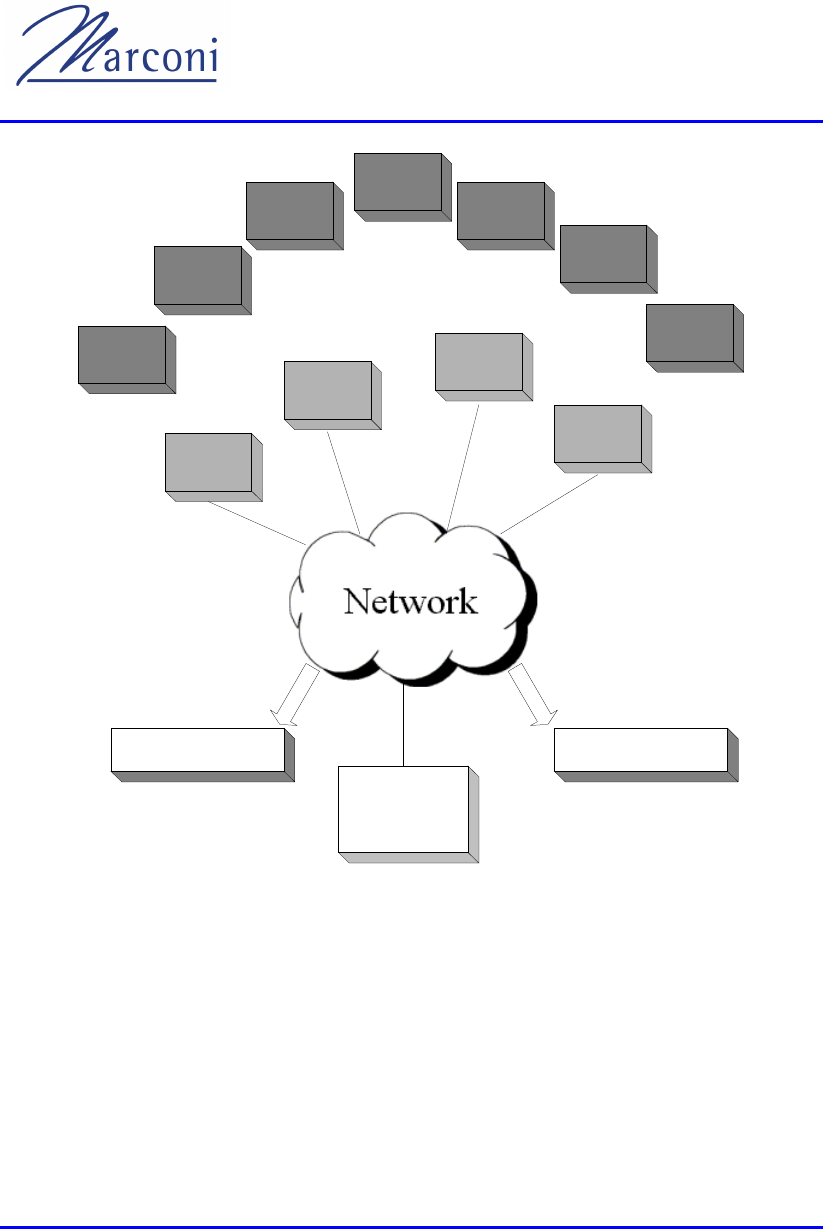
The WipLL system can be considered as functionally divided between three sites as
described in Figure 1-1:
• Subscriber Premises Sites
• Base Station Sites
• A Network Operations Center (NOC) and planning site
The Base Station Site and the Subscriber Premises site each contain WipLL
hardware whilst the NOC uses software and associated hardware platforms to plan,
configure and manage the WipLL system.
1 From WipLL Release 1.4.
Chapter
1
WipLL System Description
1-2 of 1-12 Marconi Communications Ltd. MCIL-WIPLL-SDN_R1_40
Subscriber
Site
Subscriber
Site
Subscriber
Site
Subscriber
Site
Subscriber
Site
Subscriber
Site
Subscriber
Site
Base Station
Site
Base Station
Site
Base Station
Site
Base Station
Site
Non WLL Users Non IP Systems
Network
Operating
Centre
Figure 1-1: Typical Wipll System Partitioning
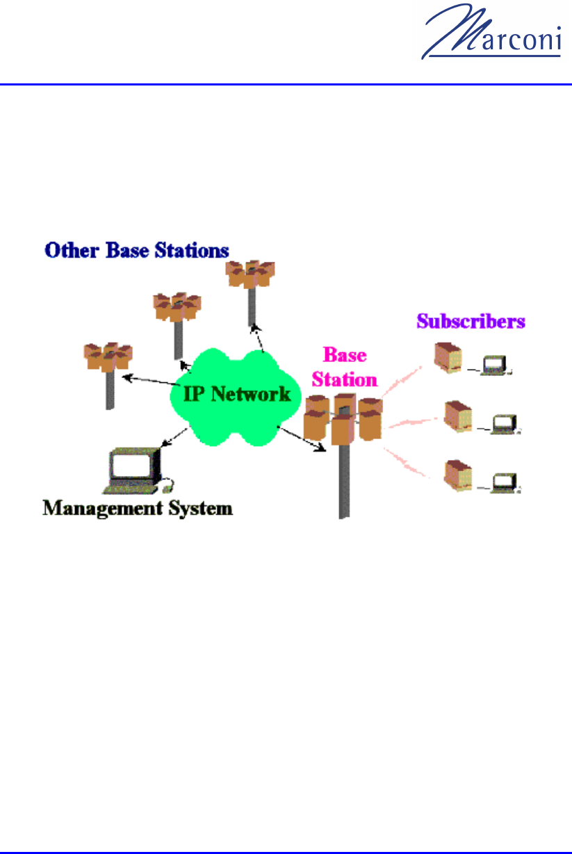
WipLL provides a radio link between the end-user of the telecom network (the subscriber)
and the network itself to give high-speed data access. WipLL uses Internet Protocol (IP) to
communicate between subscribers.
WipLL comprises radio transceivers installed at subscriber premises and further transceivers
at local base stations. A transceiver at a subscriber premises links through radio to its local
Chapter 1 - GENERAL OVERVIEW
MCIL-WIPLL-SDN_R1_40 Marconi Communications Ltd. 1-3 of 1-12
base station. The base station then links through an Ethernet connection to datacom or IP
network.
Each local base station serves numerous subscribers in its vicinity. The WipLL components
at the subscribers' premises and at the base stations can be remotely controlled and
configured by a management system using Simple Network Management Protocol (SNMP).
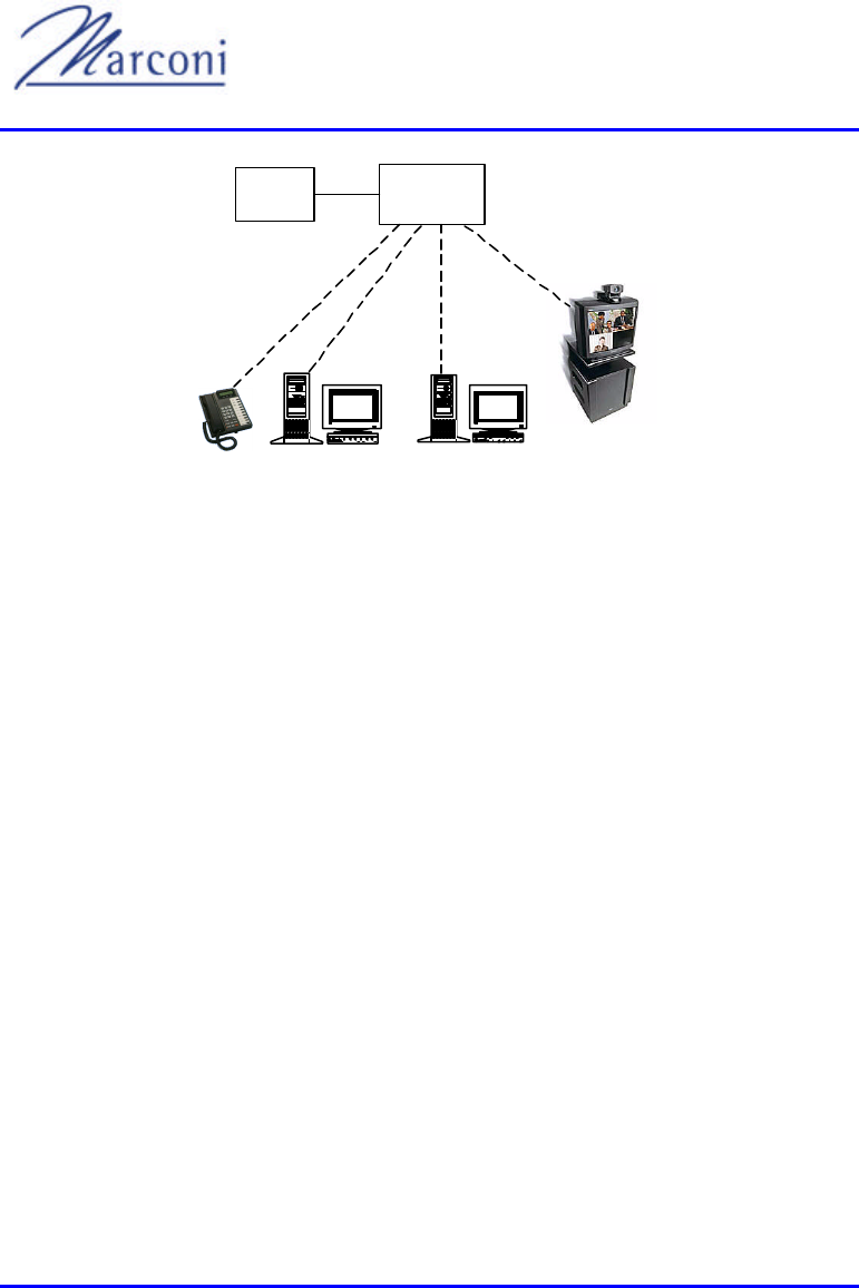
Figure 1-2 shows a diagram of a Typical WipLL installation.
Figure 1-2: Typical WipLL System
WipLL supports multiple applications integrated on a single platform, such as:
• High-rate data transfer
• Video conferencing
• Internet access
• Voice over IP

WipLL System Description
1-4 of 1-12 Marconi Communications Ltd. MCIL-WIPLL-SDN_R1_40
1.1. Components of the System
The WipLL system comprises three main components as indicated in Figure 1-1:
1) Subscriber site
2) Base station
3) Coverage
Chapter 1 - GENERAL OVERVIEW
MCIL-WIPLL-SDN_R1_40 Marconi Communications Ltd. 1-5 of 1-12
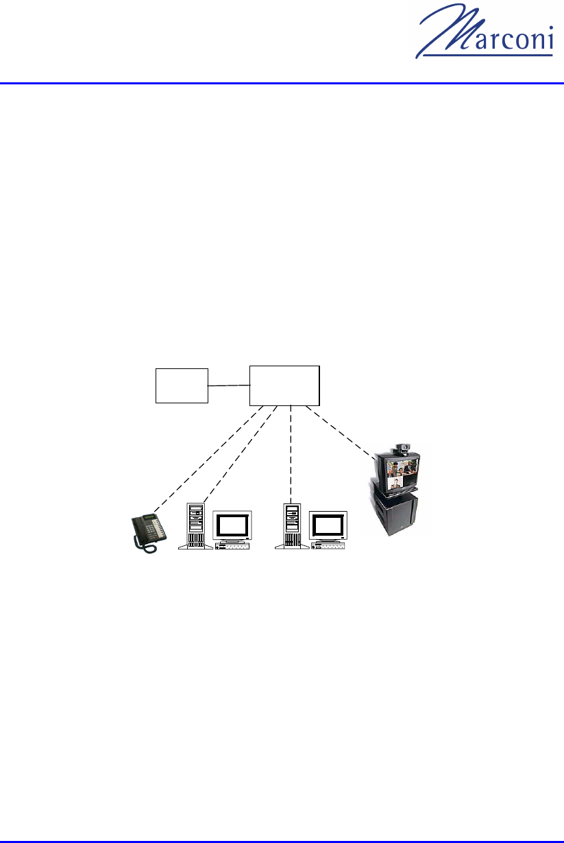
1.1.1. The Subscriber Site
Each subscriber site contains Subscriber Premises Equipment (SPE) that links the
subscriber to the WipLL system.
The SPE consists of:
• A Subscriber Premises Radio (SPR)
• A subscriber adapter or one of a set selected per application
The SPE performs routing functions between the customer site and the base station.
The SPE also performs local Quality of Service (QoS) functions, such as re-ordering
packets and assigning Time-to-Live (TTL).
The following drawing shows a current typical subscriber site installation:
SPR Subscriber
Adapter
Video
Conferencing
Figure 1-3: Typical Subscriber Configuration
WipLL System Description
1-6 of 1-12 Marconi Communications Ltd. MCIL-WIPLL-SDN_R1_40
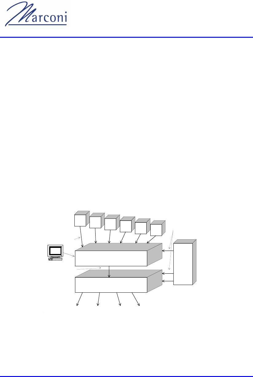
1.1.2. Base Station Components
Each base station site contains several components that enable:
• Connection to telecom system
• Internal switching of traffic
• Power supply
• Radio communications.
Some of these components are mandatory and others optional depending on the
configuration of the site and the particular type of network backbone
interconnection.
Each Base Station Radio (BSR) is optionally physically connected to a Base Station
Distribution Unit (BSDU), which provides data connectivity, power, and local
switching functionality, as well synchronization between the BSRs. A BSDU can
serve up to six BSRs, and up to four BSDUs can be chained in a single base station
to support up to 24 BSRs.
48 VDC
10 base-T
Wide Area Network
Connection
Power
Supply
BSDU
BSR BSR BSR BSR BSR BSR
100 base-T
DS1 DS3 ATM Other
Management
Figure 1-4: Base Station Units
Chapter 1 - GENERAL OVERVIEW
MCIL-WIPLL-SDN_R1_40 Marconi Communications Ltd. 1-7 of 1-12
A BSR can maintain a 3 Mbit air link with customers in its sector (net throughput of
2.4 Mb/s). A single base station has a capacity of up to 72 Mb/s and can support up
to 3024 customer sites. The area covered by a single base station is called a cell and
can extend to a radius of up to 25 km in ideal locations, about 6 km in suburban
locations and about 2 km in urban locations dependent on locally permitted RF
transmission power.
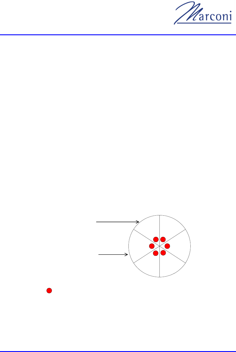
1.1.3. Coverage
Each base station provides a wireless link to all subscribers in the base station's area
or domain. For full coverage several base stations can be set up over an extended
area.
WipLL works in accordance with the operator's backbone and uses the backbone to
connect between base stations, the central management station, and other resources
on the network. WipLL assumes a network backbone that uses IP. The area covered
by a base station is divided into sectors. Each sector is built around a Base Station
Radio (BSR) unit which is the central coordinator of the sector.
The BSR can transmit and receive through a 60 degree sector. To cover a full 360
degree sweep, requires six BSRs at the base station which will comprise six sectors
each covered by a BSR.
= Base Station Radio (BSR)
60 sector
o
Area covered by
the base station
Figure 1-5: Base Station Covering 360°

WipLL System Description
1-8 of 1-12 Marconi Communications Ltd. MCIL-WIPLL-SDN_R1_40
Not all six sectors need be equipped. For example at a housing development that
faces open farmland, one could site a base station that only covers 180 degrees to
provide facilities only to the housing development.
= Base Station Radio (BSR)
60 sector
o
Figure 1-6: Base Station Giving Partial Cover
= Base Station Radio (BSR)
60 sector
o
Figure 1-7: Base Station with Complete BSR Redundancy
Alternatively, the base station can have up to twenty-four BSRs, each covering 60
degrees. This allows either:
• Complete BSR redundancy with two or more BSRs covering each sector - see
Figure 1-7
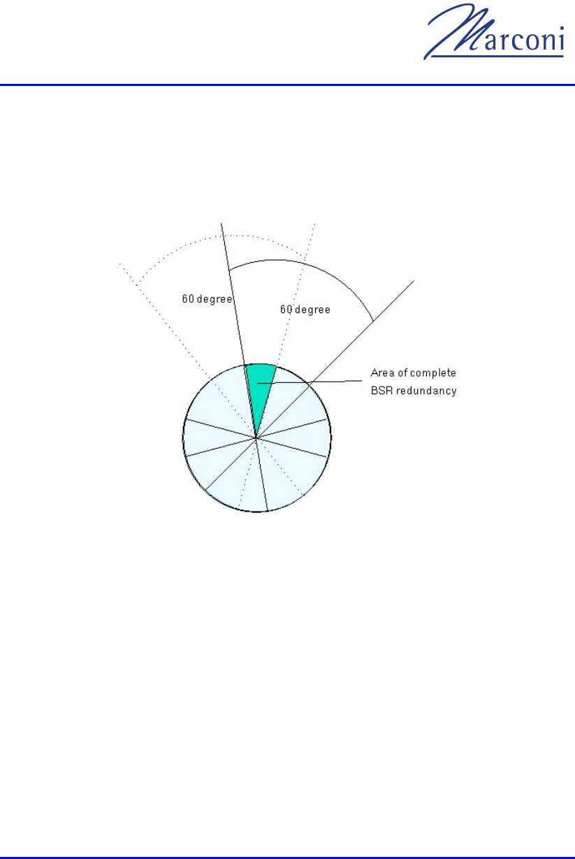
Chapter 1 - GENERAL OVERVIEW
MCIL-WIPLL-SDN_R1_40 Marconi Communications Ltd. 1-9 of 1-12
or
• Partial sector overlap with each layer of BSRs offset to the one above it - see
Figure 1-8. This gives more capacity in areas where high demand requires more
bandwidth.
Figure 1-8: Base Station Sector
1.2. Management, and Commissioning
WipLL uses two tools for management and commissioning both implemented as
software programs:
• The WipLL network management tool - WipManage
• WipConfig
Further information on the use of these tools can be found in the Operations and
Maintenance Manual.

WipLL System Description
1-10 of 1-12 Marconi Communications Ltd. MCIL-WIPLL-SDN_R1_40
1.2.1. WipManage
WipManage™ is the primary WipLL network management tool for every WipLL
unit. It enables:
• Configuration
• Fault isolation
• Performance monitoring
• Software upgrade
WipManage can access each unit in the system and manage it remotely using
standard SNMP protocols for communicating with the WipLL unit, private and
standard MIBs for setting and retrieving parameters from the units.
The top hierarchy of WipManage™ is a base-station site view from which one can
zoom into every Subscriber Premises Radio (SPR).
WipManage™ can also be run as a stand-alone program running on Microsoft
Windows NT.
Inputs to WipManage™ include the manual entry of parameters and retrieval of
parameters directly from the WipLL units. WipManage™ outputs are sent either to
the WipLL units or saved to the database as required.
1.2.2. WipConfig
WipConfig is a configuration tool for the WipLL units. It provides the flexibility to
configure the units before leaving the shop or after the actual installation at the
customer site.
WipConfig enables:
• Technicians to configure and monitor parameters at the WipLL units.
• Use of inputs from either a .CFG file that is produced by a database application
or manually by typing the parameters into the appropriate fields of the program.

Chapter 1 - GENERAL OVERVIEW
MCIL-WIPLL-SDN_R1_40 Marconi Communications Ltd. 1-11 of 1-12
• Configuration and monitoring of the WipLL units via a serial or Ethernet port. It
supports Microsoft Windows 9x and Windows 2000 platforms.

MCIL -WIPLL-SDN_R2_00 Marconi Communications Ltd. 2-1 of 2-12
MAIN FEATURES, PROTOCOL MAIN FEATURES, PROTOCOL
AND QoSAND QoS
The WipLL system is designed to provide internet access and telephony service
using spread spectrum frequency hopping technology to minimize interference in the
2.4 GHz ISM band.
Data is transmitted as Internet Protocol (IP) packets. Each packet is divided into
fragments, and fragments can be repeated several times to ensure Quality of Service
(QoS). Other techniques such as CRC and space diversity further enhance the
system performance.
WipLL is an IP based platform that enables multiple applications over a single
platform utilizing a quality of service mechanism that ensures the transmission of
packets according to a pre-defined policy.
This chapter lists the most significant features and advantages of the WipLL system,
including its protocol and Quality of Service (QoS) mechanism.
2.1. Features
WipLL was designed with the future in mind. Users, operators, service providers
and installers can benefit from WipLL's unique features.
2.1.1. User Perspective
• Always connected.
• Standard 10Base-T connection.
• High throughput.
Chapter
2

WipLL System Description
2-2 of 2-12 Marconi Communications Ltd. MCIL -WIPLL-SDN_R2_00
• Leverages new technologies and applications.
• Built-in security features.
2.1.2. Operator Perspective
Very efficient network due to:
• Single access platform for multiple applications.
• Bandwidth used only when there is real data to transmit.
• Shared bandwidth between users.
• No dedicated bandwidth to customer but capabilities to ensure throughput to the
users.
• Uncommitted direction of transmission, no need to commit to full duplex.
• Control of bandwidth and delay according to pre-defined policy.
2.1.3. Capacity
• High bit rate up to 4Mbps per channel (using 1MHz of bandwidth).
• Up to 24 BSRs per base station providing a total capacity of up to 96Mbps and
connection for up to 3024 subscribers.
• Synchronization between BSRs to enable wide area coverage .
2.1.4. QoS
• Recognition of packet and session type and assignment of resources accordingly.
• Multiple applications over the same connection.
• Bandwidth on demand.

Chapter 2 - MAIN FEATURES, PROTOCOL AND QoS
MCIL -WIPLL-SDN_R2_00 Marconi Communications Ltd. 2-3 of 2-12
• Service on demand.
2.1.5. Configuration
• Integrated IP router.
• Single outdoor box solution, i.e. no external SPR antennas or RF cables.
• Up to 100 meters of standard category 5 cable from the radio unit to the indoor
adapter.
• Standard 10Base-T interface to the subscriber site and 100Base-T interface to the
network backbone.
2.1.6. Installation and Commissioning
• Easy installation and commissioning using the WipConfig tool.
• Real time signal strength indication.
• No RF cables involved.
• All parameters can be configured lo cally or remotely.
Important!!
• BSR-2.4 and SPR-2.4 outdoor units with internal antennas should be
installedONLY by experienced installation professionals who are
familiar with localbuilding and safety codes and, wherever
applicable, are licensed by the appropriate government regulatory
authorities. Failure to do so may void theMARCONI product
warranty and may expose the end user or the service providerto legal
and financial liabilities. MARCONI and its resellers ordistributors are

WipLL System Description
2-4 of 2-12 Marconi Communications Ltd. MCIL -WIPLL-SDN_R2_00
not liable for violation of regulations associated with theinstallation
of outddor units.
• All installed units must be installed with a seperation distance of at
least 2 meters from all person during normal operation.
2.1.7. Security
• Login process with authentication mechanism.
• Data scrambling using public and private keys.
2.1.8. MAC Protocol
• Supports up to 126 subscriber sites per BSR, up to 3024 subscriber sites per base
station.
• High efficiency 80% of the bit rate.
• Automatic rate control to maximize throughput under high Bit Error Rate (BER).
• Re-transmission of lost packets reliable operation in a high BER environment
• Centrally coordinated air protocol designed for point to multipoint
environment.
• No transmission collisions.
• Real-time assessments on required and available bandwidth resources to control
data flow.
• Intelligent polling of SPRs.

Chapter 2 - MAIN FEATURES, PROTOCOL AND QoS
MCIL -WIPLL-SDN_R2_00 Marconi Communications Ltd. 2-5 of 2-12
2.1.9. Radio Communications
• Frequency hopping spread spectrum system (FH-CDMA).
• Integrated antenna diversity in a single box.
• Variety of antenna types, internal and external.
• Configurable maximum output power up to 34dBm.
• Automatic power control to minimize interference between cells and to reduce
transmission power where possible.
• Configurable frequency tables for efficient re-use of available bandwidth.
2.1.10. Management
2.1.10.1. Network Management Systems (NMS)
• SNMP agent at each WipLL unit.
• Comprehensive network management system based on SNMP for local and
remote management.
• Standard and proprietary Management Information Bases (MIB).
• Configuration management.
• Fault isolation.
• Performance monitoring.
• Software upgrade of every WipLL unit using TFTP.
• Support for standard IP protocols ARP, DHCP relay, TFTP, ICMP, SNMP.

WipLL System Description
2-6 of 2-12 Marconi Communications Ltd. MCIL -WIPLL-SDN_R2_00
2.1.11. System Parameters
• Temperature range of
• Compliance with ETSI and FCC Regulations.
2.1.12. RF
This environment consists of point to multi-point directional antennas pointing
towards the base station. Distances between stations and the base station may differ.
Some may be near while others may be far away.
Additional features include:
• Multi-site mutual interference.
• Frequency hopping.
• Multi-rate: Sensitivity of the receiver changes and is dependent on the bit rate.
2.1.13. Network
• Ethernet packets between 64 and 1518 bytes.
• Burst of packets or constant flow to/from users depending on the application.
2.1.14. Application
Data different types of applications generate requirements for:
• Assignment of delays.
• Allowed packet loss rate that applications can sustain.
• Bandwidth for the application - video requires constant signal flow:

Chapter 2 - MAIN FEATURES, PROTOCOL AND QoS
MCIL -WIPLL-SDN_R2_00 Marconi Communications Ltd. 2-7 of 2-12
• Packets are generated usually every 30ms. (depending on the Residential
Access Gateway (RAG) and sampling rate)
• Requires minimal delay.
• Silence suppression no packets
2.2. PPMA Protocol
This section describes the Preemptive Polling Multiple Access (PPMA) protocol. It
discusses the environment in which this protocol operates, its task and description of
the PPMA protocol as used by WipLL.
To support the above environment the main task of the PPMA protocol is to
combine all these requirements in the most efficient manner.
2.2.1. What is PPMA?
2.2.1.1. Concept
PPMA is a centrally coordinated protocol. The BSR performs the task of
coordination over the air. It constantly gathers information from the Subscriber
Premises Radio (SPR) regarding their requirements for resources. These are rated
according to the combination of parameters such as the number of packets in the
SPR queues and the maximum allowed delay for the first packet in the queue.
Once the BSR has determined the requirements of resources for the next few
milliseconds it starts to poll the SPRs accordingly. SPRs that receive the highest
score are polled first and the others follow in order.
2.2.1.2. Slotted Aloha Process
The constant gathering of information regarding the required resources from the
SPRs is performed by using a mechanism called "Slotted Aloha".
From time to time (and not exceeding every 100mS) the BSR sends a "Channel
Clear" message which is an invitation for SPRs to send the score of their
requirements. It then waits for a while and receives these requirements from the

WipLL System Description
2-8 of 2-12 Marconi Communications Ltd. MCIL -WIPLL-SDN_R2_00
SPRs. The waiting time is called Slotted Aloha due to the fact that the BSR waits
for a time that is equivalent to 16 messages of "Request to Send" (RTS). The
messages are synchronized so that an SPR does not transmit a message before the
previous message is ended. The timing of each RTS message is represented as a
"Slot".
SPRs are independent to choose which slots to use for sending their requirements.
Occasionally a collision between SPRs can occur on a slot and then the probability
is that the request is lost. Each SPR can use more than one slot to send its request.
An SPR that was not allowed to transmit might try again during the next Slotted
Aloha process.
This system ensures that all SPRs eventually get a fair chance to transmit their
requests.
2.2.1.3. Packet Transmission
After the BSR has gathered the requests from the SPRs and decided on the priorities,
it sends a "Clear to Send" (CTS) message to the first SPR. The packet is then
transmitted from the SPR.
In the header of each packet more information about the status of the queues is
included thus avoiding the need for the SPR to participate in the next Slotted Aloha
process.
The data packet is divided into fragments and each fragment is added with CRC
(Cyclic Redundancy Check). After the packet is complete, an "Acknowledge"
(ACK) message is sent by the BSR that includes information about all fragments
that were reported as errors. These fragments can be repeated several times until the
entire message is successfully transmitted.
2.2.1.4. Polling Sequence
Each time the BSR sends a CTS (Clear to Send) message to one of the SPRs it is
considered as if the SPR is being polled.
Polling of SPRs can happen according to the information gathered during th e Slotted
Aloha process or in a periodic manner every few milliseconds regardless of the
Slotted Aloha process depending on the application transmitting data at the time.

Chapter 2 - MAIN FEATURES, PROTOCOL AND QoS
MCIL -WIPLL-SDN_R2_00 Marconi Communications Ltd. 2-9 of 2-12
The polling sequence of data applications is managed by the BSR based on the
information gathered during the Slotted Aloha process. Data applications can sustain
relatively long delays before expecting a response and therefore their packets can be
delayed within the SPRs before being sent to the BSR and on to the network. Other
applications which require a smaller delay for their packets are polled first.
Some applications are configured to transmit a burst of several packets in a row
before expecting any response from the other party. In such a case the polling
mechanism is able to support several polls of an SPR one after the other.
This mode is called "PPMA" (Preemptive Polling Multiple Access).
Real-time applications such as video often sends a constant flow of packets. In this
case the BSR polls the SPR that is related to such an application in accordance with
the flow of the packets. IP Telephony systems send packets about every 30ms and
require a very small delay. Therefore, an SPR that was recognized as sending
packets is polled usually every 30ms (see 2.1.14) without having to go through the
Slotted Aloha process to inform the BSR about each packet.
This mode is called "Adaptive TDMA" (Time Division Multiple Access).
2.3. Security
Being a centrally coordinated protocol gives PPMA several options of security that
are independent of other layers.
2.3.1. Login Mechanism
In order to be served by a BSR an SPR must be registered to it. This registration
process is based on the SPR's MAC address and the BSR address that is configured
by the network management.
When a new SPR tries to register to the BSR it sends an "Request to Send" message
during the "Slotted Aloha" time. The BSR then checks if the SPR MAC address is
listed as an "Allowed SPR" list. This list is maintained by the network management
system. If it is listed as such then an "Association" message is sent to the SPR that
includes information about the cell such as the public key for the encoding, number
of users, etc.. The SPR then sends its own information to the BSR. It is then
considered as being "associated" with the BSR and can start sending and receiving
messages from it.
WipLL System Description
2-10 of 2-12 Marconi Communications Ltd. MCIL -WIPLL-SDN_R2_00
In case the SPR is not included in the "Allowed SPR" list or the address it provides
for the BSR is incorrect no message will be sent to it and the association process will
be terminated.
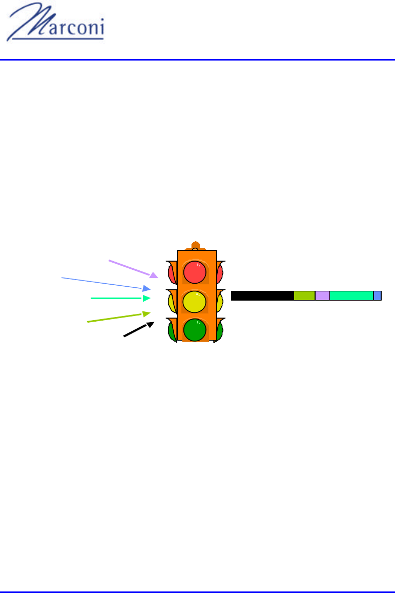
2.4. QoS
Quality of Service (QoS) is the ability to recognize the type of the transmission and
assign bandwidth and other resources accordingly.
Resources are not necessarily only in terms of bandwidth but also in terms of delays,
packet loss rate and whether or not data needs to be retransmitted in case it is lost.
Figure 2-1 represents the idea behind the QoS. Some applications require more
network resources than others.
WEB Browsing
E-mail
File Transfer
Voice over IP
Video Conference
Figure 2-1: WipLL QoS Mechanism
Qos measurements are based on 2 factors, assigned traffic priority (0 through 7) and
Time-To-Live (TTL) factor (1 through 5):
1) Network protocol - IP
2) Transport protocol TCP, UDP, ICMP
3) Transport protocol and port number (based on application type)
4) IP address
5) Session type - VoIP
Chapter 2 - MAIN FEATURES, PROTOCOL AND QoS
MCIL -WIPLL-SDN_R2_00 Marconi Communications Ltd. 2-11 of 2-12
2.5. Echo Management
Packet based systems are likely to introduce more delay (and variable) than circuit
switched systems. Increased delay could present quality problems with time
bounded services such as voice communication.
SPR
1
PSTN
IP Network
Base Station Site
1
n
BSR
10BaseT
10BaseT
H-E
GW
GW
International
Traffic
Ethernet
SDTA
SDTA
Ethernet
Switch
Ethernet
RJ-11
RJ-11
Figure 2-2: Echo Control
As can be seen from Figure 2-2, echo becomes an issue when a voice call is
established between a customer connected to an SDTA and a PSTN customer. Echo
is generated at the 2 wire-4 wire hybri
be cancelled. Note that a voice call between two customers, both connected to an
SDTA, will not suffer from echo because the SDTA customers effectively become
4-wire customers.

WipLL System Description
2-12 of 2-12 Marconi Communications Ltd. MCIL -WIPLL-SDN_R2_00
PSTN has traditionally been a low delay network and has not bothered with echo
cancellation, at least in smaller countries, if the round trip delay is below 50ms.
Echo cancellors are used in international calls between different PSTNs.
The key principle is that the network that causes the echo should cancel it. Applying
this principle to the introduction of IP based WLL systems means that echo should
system echo cancellation has been implemented in both the SDTA (upto 8ms) and
the head-end gateways (upto 64ms).

MCIL -WIPLL-SDN_R2_00 Marconi Communications Ltd. 3-1 of 3-10
APPLICATIONS AND APPLICATIONS AND
SERVICESSERVICES
WipLL can be installed in several configurations to support different required
applications. The following paragraphs discuss some of the applications and services
that can be provided with WipLL.
3.1. Applications
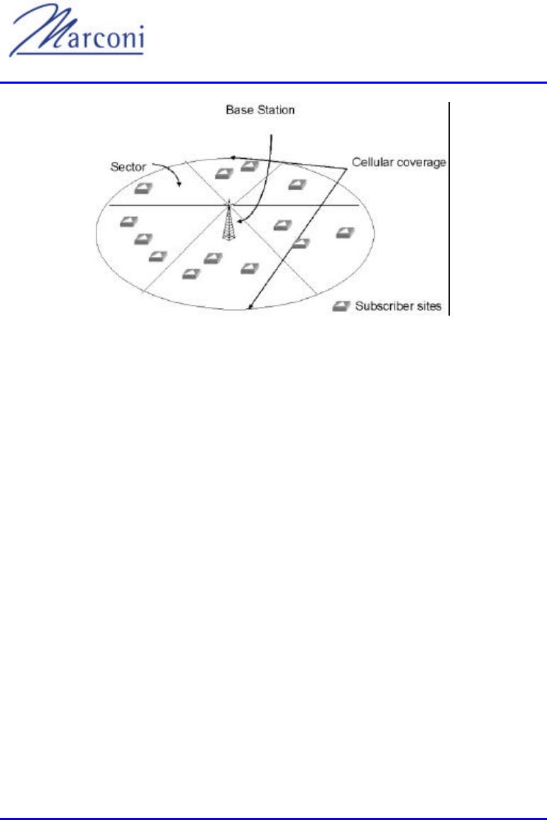
3.1.1. Fixed Cellular Access System
Typically WipLL is used as a broadband fixed wireless access system. It is installed
in a cellular structure where many base station sites are installed in a way that
provides full coverage of an area for enabling access for all potential customers in
the area.
Each cell consists of sectors that are determined by base station radios (BSRs).
The following figure shows the structure of a typical WipLL cell.
Chapter
3
WipLL System Description
3-2 of 3-10 Marconi Communications Ltd. MCIL -WIPLL-SDN_R2_00
Figure 3-1: WipLL Cell
Subscriber Premises Radios (SPRs) are normally installed on a rooftop or a wall
which has a direct line of sight to the base station radio (BSR) and are pointed
towards the nearest base station or the base station that was assigned according to
the pre-planning of the site.
well as enough capacity to accommodate the requirements of subscribers.
When a full area is covered, WipLL can provide services to tens of thousands of
users. The backbone must be able to carry the required capacity, delays and
connectivity in order to support the services and requirements of all users.
Prior to installation, a full site planning is required. Such planning normally includes
forecasts of the required capacity based on the number of users, typical subscription
contract, types of srevice, required bit rate per subscriber, etc.
It also includes radio planning for determining the best locations for BSRs to
ensure full coverage, frequency allocation to minimize mutual interference and
tilting options to determine the covered area for each sector of a base station.

Chapter 3 - APPLICATIONS AND SERVICES
MCIL -WIPLL-SDN_R2_00 Marconi Communications Ltd. 3-3 of 3-10
Important!!
o BSR-2.4 and SPR-2.4 outdoor units with internal antennas should be
installedONLY by experienced installation professionals who are
familiar with localbuilding and safety codes and, wherever
applicable, are licensed by the appropriate government regulatory
authorities. Failure to do so may void theMARCONI product
warranty and may expose the end user or the service providerto legal
and financial liabilities. MARCONI and its resellers ordistributors are
not liable for violation of regulations associated with theinstallation
of outddor units.
o All installed units must be installed with a seperation distance of at
least 2 meters from all person during normal operation.
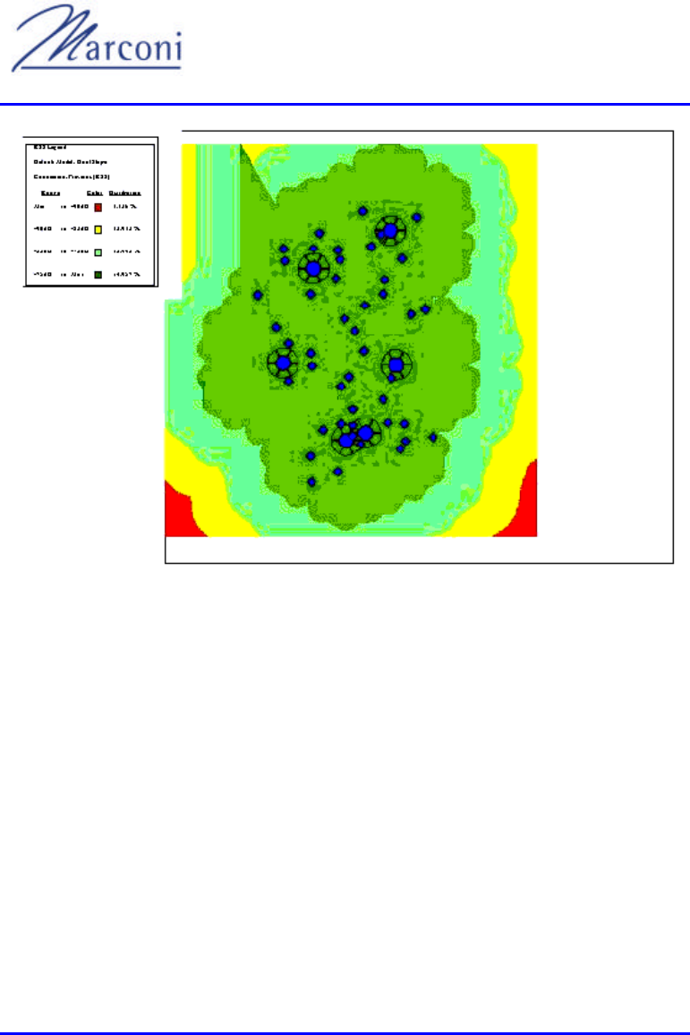
3.1.2. Connecting the Base Station to the Network
Backbone
-T
connections.
Figure 3-2 shows planning of a few base stations that cover an area.
WipLL System Description
3-4 of 3-10 Marconi Communications Ltd. MCIL -WIPLL-SDN_R2_00
Figure 3-2: WipLL Coverage Planning
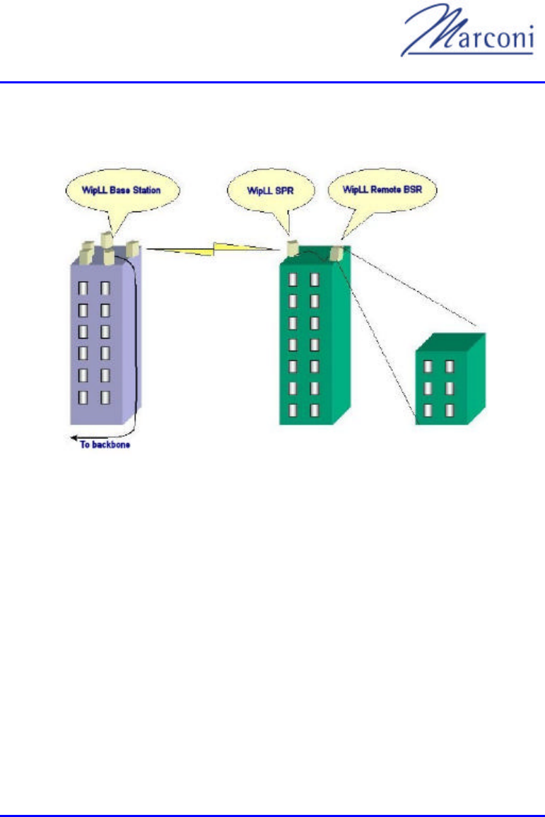
3.1.3. Remote Base Station Backhaul
Occasionally, when base stations are providing services to a small number of
subscribers or when large capacity is not required, WipLL SPRs and BSRs can be
used for backhauling.
Such configurations can be considered in most cases as a point-to -point (PTP)
connection.
Each PTP connection can provide up to 4Mbps of bandwidth and is equivalent or
better than a typical point-to-multi-point (PMP) connection that is used in a typical
base station installation.
Chapter 3 - APPLICATIONS AND SERVICES
MCIL -WIPLL-SDN_R2_00 Marconi Communications Ltd. 3-5 of 3-10
Figure 3-3 shows a typical backhauling of a base station using WipLL.
Figure 3-3: WipLL Backhauling
Remote base stations are typically required when the main base station sites cannot
cover an area due to lack of line-of-sight or when the distance exceeds the capability
of the radios to provide services.
It is recommended that a maximum of two hops be used between a main base station
and a subscriber site.
Note: Each such connection adds about 15 to 25ms delay to each packet.
WipLL System Description
3-6 of 3-10 Marconi Communications Ltd. MCIL -WIPLL-SDN_R2_00
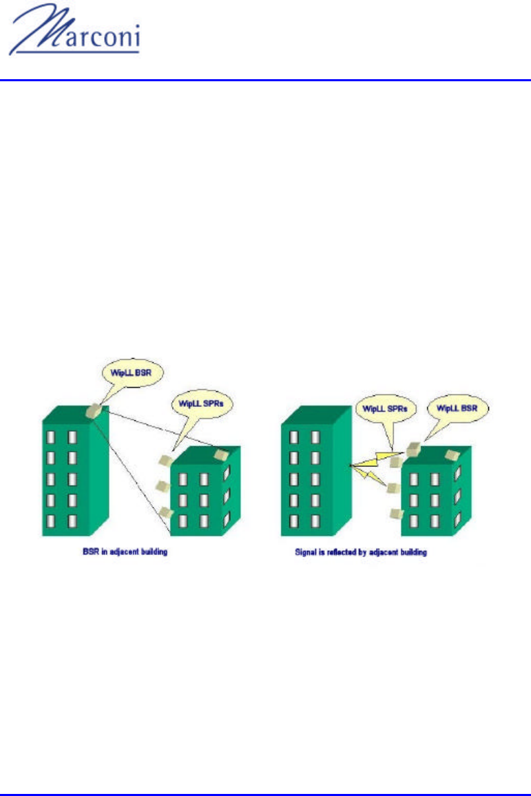
3.1.3.1. Indoor Coverage (Not for use in North America)
In many applications there is a need to provide access to users located in the lower
floors of a building. These users usually do not have a direct line -of-sight with a
base station. WipLL can be used for indoor coverage for apartment buildings and
office areas.
There are ways to achieve such a configuration either by placing the BSR in a an
adjacent building and covering one or two sides of the building or placing a BSR on
the roof pointed towards the adjacent building to receive the reflections of the RF
signals, or by placing the BSR inside the building and transmitting sufficient power
to penetrate walls.
The following figures show some ways of providing indoor coverage.
Figure 3-4: WipLL Indoor Coverage

Chapter 3 - APPLICATIONS AND SERVICES
MCIL -WIPLL-SDN_R2_00 Marconi Communications Ltd. 3-7 of 3-10
3.2. Services
3.2.1. Broadband Data Access
Using a standard PSTN modem in circuit-switched networks customers are limited
to 56Kbps of throughput and in most cases to 28.8Kbps.
From the operator's perspective once a customer has dialed with a PSTN modem a
full 128Kbps channel is occupied for as long as the session lasts.
With WipLL customers are limited only by configuration, with a maximum of
4Mbps, 50 times faster than the fastest PSTN modem.
However, they do not necessarily consume more bandwidth from the operator since
bandwidth is used only when there is an actual data packet to transmit. This happens
about 10% of the time.
As a result, assuming the same bandwidth utilization of 128Kbps per customer an
operator may actually commit 128Kbps to each customer, thus over-selling
bandwidth without having any effect on the performance of the connection.
These characteristics of WipLL make it suitable for providing data access to users
while maintaining best usage of bandwidth and capacity.
The following paragraphs discuss some of the services available with the broadband
access that WipLL can offer.
3.2.2. High Speed Internet Access
One of the advantages of WipLL is the fact that users are "always on". This means
that there is no dialing process and no need for the hassle involved with dialup
access. You need only open your web browser or email program to be instantly
connected.
WipLL System Description
3-8 of 3-10 Marconi Communications Ltd. MCIL -WIPLL-SDN_R2_00
WipLL can also distinguish between applications and users, thus enabling the
operator to provide different class of service to users. For example, it can provide
different services to web browsing and email, prioritizing web browsing for ensuring
best "Internet experience".
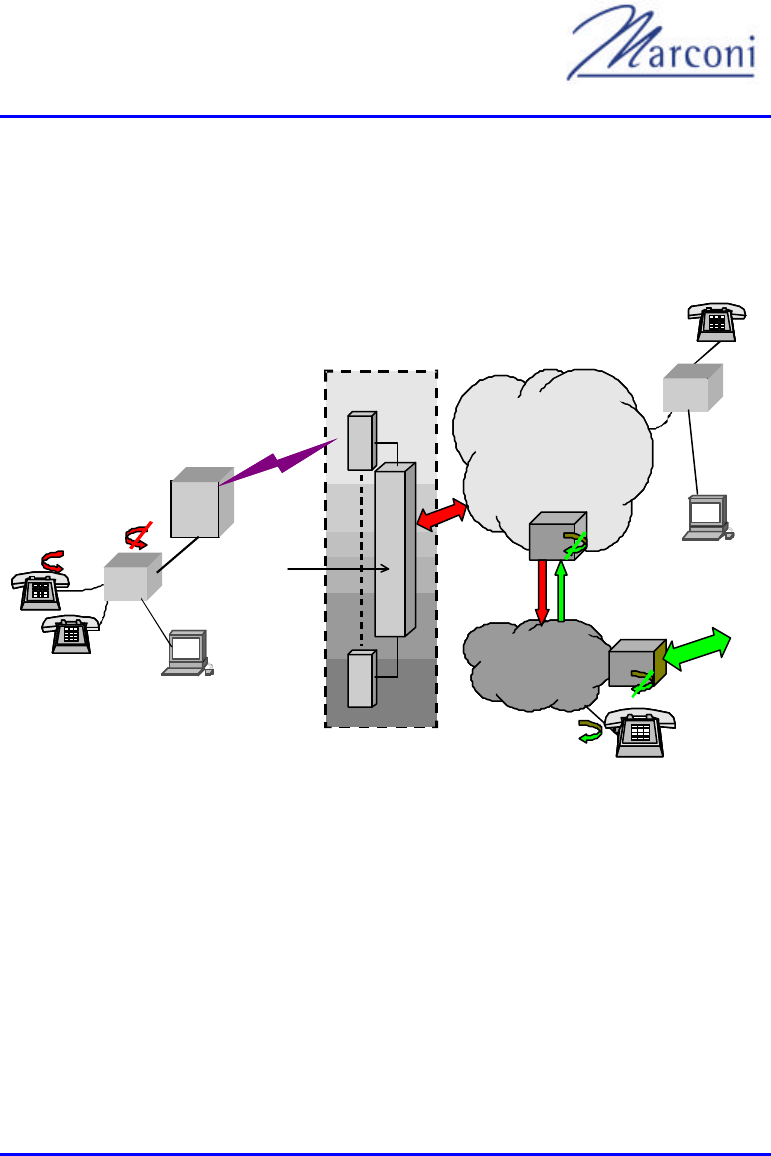
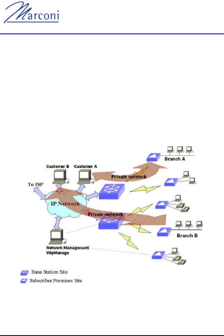
3.2.3. Private Networks
WipLL allows the configuration for providing connectivity to branch offices. In this
configuration the branch office can be connected to a central office or any other
destination without allowing access from any other source.
Figure 3-5 illustrates two customers, A and B, with private networks to branch
offices.
Figure 3-5: WipLL Private Networking

Chapter 3 - APPLICATIONS AND SERVICES
MCIL -WIPLL-SDN_R2_00 Marconi Communications Ltd. 3-9 of 3-10
3.2.4. Remote Access
WipLL is very suitable for tele -workers who require high speed access combined
with private network and flexible configuration.
The interface to the system is 10Base-T and enables seamless configuration between
office and remote location.
3.2.5. Video Over IP
The fact that WipLL can provide Mbps of throughput to the user, together with its
ability to set different delays and priorities to different applications and provide
QoS, makes it a good solution for enabling applications like video over IP.
This means that customers can do high quality video conferencing.
The system can prioritize video packets in such a way that delays and jitter are
minimized and the video packets pass smoothly through the system.

WipLL System Description
3-10 of 3-10 Marconi Communications Ltd. MCIL -WIPLL-SDN_R2_00
This page intentionally left blank

MCIL -WIPLL-SDN_R2_00 Marconi Communications Ltd. 4-1 of 4-10
BSRBSR
4.1. Base Station Radio
A BSR is the centre of a WipLL sector. It has several roles in both the MAC layer as
well as in the networking and transport layers. In the MAC layer the BSR is
responsible for synchronizing the SPRs in terms of timing, frequency hopping
sequence, authentication, and control - allowing (or not) the transmission of data
within the sector.
At the network layer the BSR performs routing functions between the base station's
Ethernet network and the wireless stations, containing a routing table that can
support up to 126 stations addresses. The transport layer at a BSR makes decisions
on how to support an application in terms of bandwidth, delays and mode of
operation.
There are two modes of operation - Pre-emptive Polling (PPMA) and Time Division
Multiple Access (TDMA). Although the WipLL BSR employs PPMA, it also
recognizes the traffic type and emulates TDMA where necessary.
The BSRs are connected to the wired backbone through a BSDU with a 10Base-T
Ethernet connection which allows a cable length of up to 100 meters.
Each of the BSRs contains two internal high gain, flat plate antennas, to support
functionality of antenna diversity which helps to overcome multi-path effects.
There are typically several BSRs at each base station site. Each BSR can cover an
azimuth angle (yaw) of 60 degrees and therefore 6 BSRs can provide a full 360
degrees coverage of the entire cell if needed. The antenna may also be tilted
vertically (pitch) to reduce interference between adjacent BSRs. The maximum
number of radios that can be connected depends mainly on the radio bandwidth
allocated to the system. 6 radios can coexist at the base-station providing as much
Chapter
4
WipLL System Description
4-2 of 4-10 Marconi Communications Ltd. MCIL -WIPLL-SDN_R2_00
as 18 Mbit /s per base station to be shared among the remote users. Each individual
BSR delivers up to 4Mbps using only a minimal 1MHz of radio bandwidth. As
capacity demand grows, more BSR's can be added to a total of 24 per cell, providing
approximately 96Mbps throughput and connection to up to 3,024 discrete subscriber
sites, however such a configuration would require a bandwidth allocation of at least
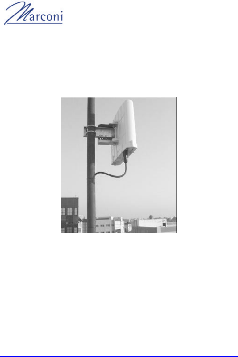
75 MHz.
Figure 4-1: Typical BSR Installation
4.1.1. BSR Default Accessories
• Mechanical mounting kit. Each BSR comes with a kit for mounting the unit on a
pole with means for tilting.
• Data connector. A DB15 connector with waterproof cover included with the
BSR.

Chapter 4 - BSR
MCIL -WIPLL-SDN_R2_00 Marconi Communications Ltd. 4-3 of 4-10
• From WipLL Release 1.4, the BSR will also have an optional N-Type connector
for attaching an optional 3rd -party external antenna1 (Not for North America only
for ETSI countries).
4.2. Network Management
The BSR is managed using SNMP and standard proprietary MIBs for the specific
configurations of the BSR
4.2.1. Capabilities
• Configuration - network parameters (IP address, ports, routing tables, etc.), RF
parameters (frequency tables, allowed CS, etc.)
• Traps - sends traps as per configuration.
• Fault management - debugging options.
• Counters - for statistics on packet loss.
1 For 2.4GHz application only, an external antenna may have a gain of 5-15dbi.
Responsibily of compliance is left to the customer.
WipLL System Description
4-4 of 4-10 Marconi Communications Ltd. MCIL -WIPLL-SDN_R2_00
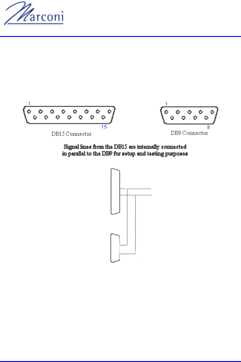
4.2.2. Physical Interfaces
• DB15 connector - power, Ethernet, sync and serial.
• DB9 connector - for serial interface.
Figure 4-2: BSR Assembly

Chapter 4 - BSR
MCIL -WIPLL-SDN_R2_00 Marconi Communications Ltd. 4-5 of 4-10
Table 4-1: Antenna Unit Connectors
9 Pin Communications Connector 15 Pin Data/Power Connector
1 nc 1 + VIN F
2 Rx 2 - VIN F
3 Tx 3 Ethernet Tx +
4 nc 4 Ethernet Tx -
5 Ground 5 Ethernet Rx +
6 nc 6 Ethernet Rx -
7 Ground 7 nc
8 nc 8 nc
9 +5vDC 9 +VIN F
10 - VIN F
11 VCC
12 GND
13 nc
14 232 Rx
15 232 Tx
4.2.3. Communication Interfaces
• Ethernet, 10Mbps.
• Serial, RS-232.

WipLL System Description
4-6 of 4-10 Marconi Communications Ltd. MCIL -WIPLL-SDN_R2_00
4.2.4. Features and Protocols
4.2.4.1. Features
• Synchronization of hops between BSRs.
• Software upgrade - with TFTP.
• Static routing tables - 16 entries per each SPR plus 32 entries for the Ethernet
side, total 256 x 16 entries - 4096 routing entries.
• QoS - proprietary.
• Network management - SNMPv2
• Multiple concurrent open sessions - up to 50
4.2.4.2. Protocols
• ARP
• DHCP / BOOTP relay
• TFTP
• ICMP
• SNMP

Chapter 4 - BSR
MCIL -WIPLL-SDN_R2_00 Marconi Communications Ltd. 4-7 of 4-10
Table 4-2: BSR and MAC Specifications
Parameter Value Comment
Operating frequency range
Rel 1.2
Rel 1.4
2.4GHz
2.4GHz
Spectrum spreading method Frequency hopping CDMA Per ETSI EN300 328
Duplex method Time division (TDD) - 2.4GHz
Transmit bit rates Up to 4Mbps BER and distance dependent.
Channel spacing 1MHz
Output power from the radio Up to 23dBm, configurable Depending on local regulations
maximum output power can be
set at factory
Effective Isotropic Radiated
Power (EIRP) Up to 34dBm, configurable Depending on local regulations
maximum output power can be
set at factory
Modulation method 8 level CPFSK
Channel access method PPMA / Adaptive TDMA
Protocol efficiency Up to 80% At BER = 10-5 , depending on
the application
Number of SPR per BSR Up to 126 62 concurrently
Table 4-3: BSR Agency Certification
Parameter Value Comment
Emissions / Immunity EN 300 339 EN 300 386-2
ETS300 328
Safety EN / IEC 60950
Environmental ETS 300 019-2-x
Table 4-4: BSR Network Specifications
Parameter Value Comment
Filtering Rate 10500 Frames / sec

WipLL System Description
4-8 of 4-10 Marconi Communications Ltd. MCIL -WIPLL-SDN_R2_00
Forwarding Rate 1400 Frames / sec
Routing table length 64 x 16
Data open -sessions per BSR 50
Table 4-5: BSR Power Requirements
Parameter Value Comment
Voltage
Minimum:
Maximum:
48Vdc nominal
30Vdc
55Vdc
Fed from the BSDU
Amperes
Maximum:
500mA
Table 4-6: BSR Environmental Conditions
Parameter Value Comment
Operating Temperature
Outdoor units
(BSR,SPR)
- Optional range of -
Storage Temperature -
Table 4-7: BSR Network Interface
Parameter Value Comment
Ethernet Network UTP EIA/TIA Category 5
Standards Compliance ANSI/IEEE 802.3 and ISO /IEC
8802-3 10 Base-T compliant
Serial Port RS-232

Chapter 4 - BSR
MCIL -WIPLL-SDN_R2_00 Marconi Communications Ltd. 4-9 of 4-10
Table 4-8: BSR Physical Dimensions
Parameter Value Comment
Height 400mm
Width 317mm
Depth 65.5mm
Weight 4.7kg
Excluding mounting kit
WipLL System Description
4-10 of 4-10 Marconi Communications Ltd. MCIL -WIPLL-SDN_R2_00
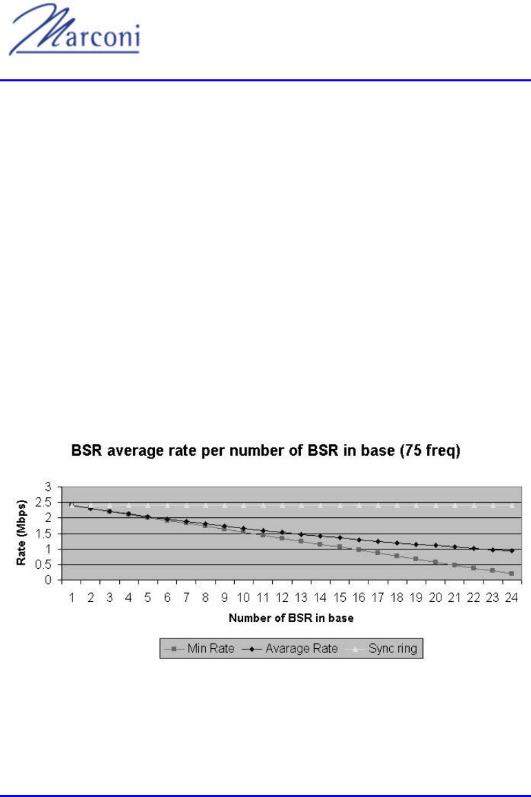
4.2.5. Unsynchronized vs Synchronized Operation
(Not for North America only for ETSI countries).
In unsynchronized mode, BSRs use random frequency tables. As such signal
collision is quite possible leading to frequent retransmission. Using orthogonal
tables helps to reduce this to a limited extent.
In synchronized mode, all BSRs use the same frequency table. A signal received
from the BSDU restarts the table phase. Up to 4 BSDUs may be daisy chained
together, in which case each BSDU will be assigned as Sync Ring Id and the master
BSDU will be the one to send the restart signal.
The GPS is designed to synchronize across base stations. 1 GPS can support upto 4
co-located BSDUs. If only one of the BSDUs has a GPS, that BSDU will
automatically be assigned as the master. If each BSDU has its own GPS or if there
are no GPSs installed on any of the BSRs, WipLL will assign a master BSDU Id to a
Sync Ring Id.
Figure 4-3: Sync/Unsync BS Capacity Comparison
MCIL -WIPLL-SDN_R2_00 Marconi Communications Ltd. 5-1 of 5-8
BSDUBSDU
5.1. Base Station Distribution Unit
The Base Station Distribution Unit (BSDU) is a major building block of the base
station. It performs the main indoor functions of the WipLL base-station. This
mainly refers to the interfacing function between the Base Station Radios (BSRs),
the Wide Area Network (WAN) and the DC power system.
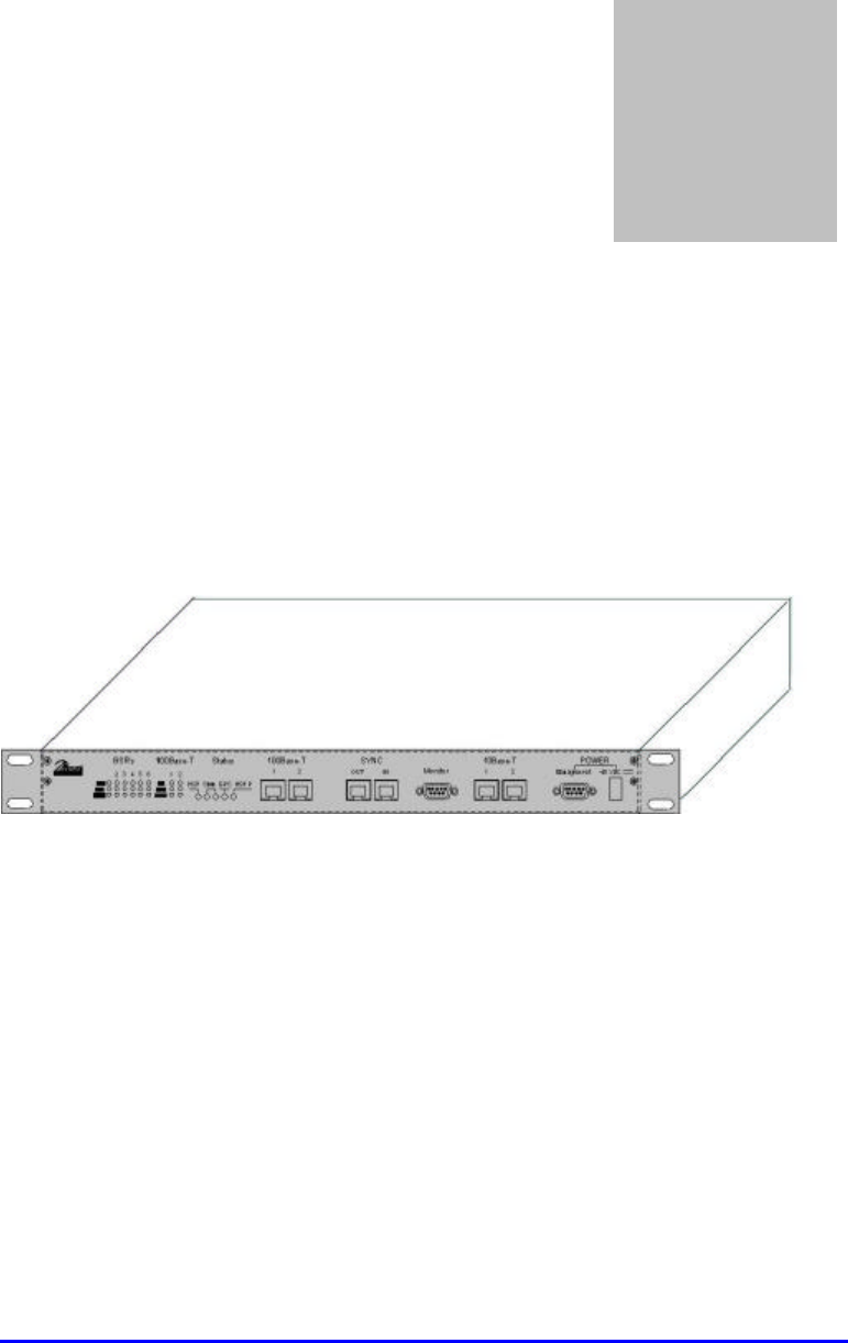
Figure 5-1: The WipLL BSDU
The functions implemented by the BSDU in the WipLL system's base station are:
• Data switching. - between 6 BSRs to a fast Ethernet 100Base-T port.
• Power distribution - DC power from a single -48Vdc connection to six BSRs.
• Domestic functions - focusing on local functions of the base station such as Hop-
synchronization, power alarms, etc.
-T RJ45
-T RJ45 sockets, Sync in and Sync out RJ45 sockets, a DB9
socket for a monitor and a DB9 socket for management. The rear of the device has 6
DB15 connectors for connecting to each of the BSRs, cables and connectors for
Chapter
5

WipLL System Description
5-2 of 5-8 Marconi Communications Ltd. MCIL -WIPLL-SDN_R2_00
connecting to other BSDUs, a DB15 connector for the GPS plus mechanical
brackets for mounting the BSDU unit in a 19" rack
5.2. Network Management
5.2.1. Management Information Base
• Standard Management Information Base (MIB) - Ethernet, switch. From WipLL
Release 1.4, WipManage also controls the BSDU using SNMP.
• Marconi proprietary MIBS for managing the hop synchronization plus other
specific parameters
5.2.2. Capabilities
• Configuration - network parameters
• Traps - sends traps as per configuration.
• Fault management - debugging options.
• Statistical counters - packet loss, etc.
5.3. Physical Interfaces
5.3.1. Connectors
• DB15 connectors for power, Ethernet, sync and connection to the BSRs.
• DB15 connector for power and signal connection to the GPS
• DB9 connectors for monitor and management.

Chapter 5 - BSDU
MCIL -WIPLL-SDN_R2_00 Marconi Communications Ltd. 5-3 of 5-8
• -T.
• -T.
•
5.3.2. Communication Interfaces
• Fast Ethernet, 100Base-T
• Ethernet, 10Mbps.
• Serial, RS-232.
5.4. Features and Protocols
5.4.1. Features
• Synchronization of hops between BSRs - the BSDU is the master (Not for North
America it is only for ETSI countries).
• Software upgrade - with TFTP.
• Network management - SNMPv2
5.4.2. Protocols
• ARP
• TFTP
• ICMP
• SNMP

WipLL System Description
5-4 of 5-8 Marconi Communications Ltd. MCIL -WIPLL-SDN_R2_00
5.5. Table of Specifications - BSDU
5.5.1. Network Specifications
• Filtering rate - 105 000 frames / sec.
• Forwarding rate - 62 500 frames / sec.
5.5.2. Power Requirements
• Voltage- 48v DC nominal
• Power consumption -
5.5.3. Environmental Conditions
• Operating temperature 0C to +50C
• Storage temperature -40C to +80C
5.5.4. Network Interface
• Ethernet Network - RJ45: UTP EIA/TIA - Category 5
5.5.5. Standards Compliance
• ANSI/IEEE 802.3, ISO/IEC 8802-3 10/100 Base-T compliant
• Serial port - RS-232
Chapter 5 - BSDU
MCIL -WIPLL-SDN_R2_00 Marconi Communications Ltd. 5-5 of 5-8
5.5.6. Physical Dimensions
Table 5-1: BSDU Physical Dimensions
Parameter Value
Height 4.32 cm
Width 48.26 cm
Depth 22.86 cm
Weight 2.9 kg
5.6. GPS (not for use in North America, only in
ETSI countries).
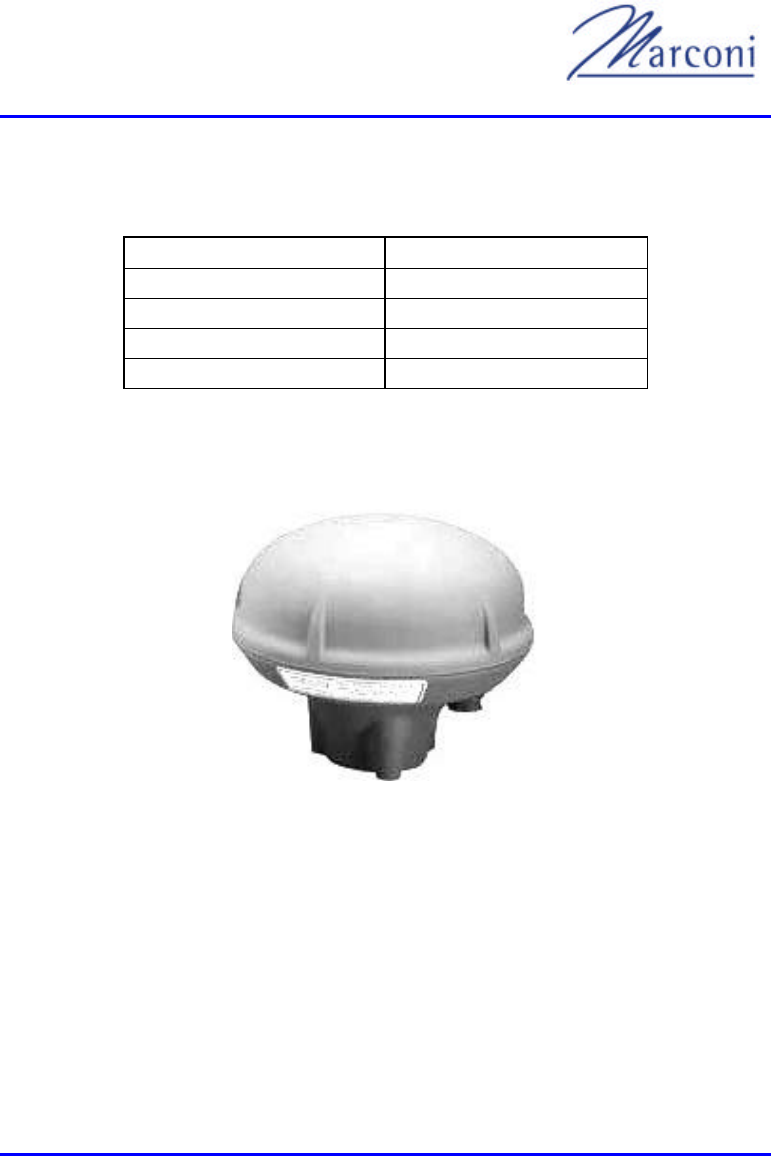
Figure 5-2: Global Positioning System (GPS) Antenna
In order to synchronize a multiple BSDU environment and avoid RF ghosting
effects it is critical that the entire network operates with the same clock. To achieve
this, base stations are equipped with a GPS antenna, which receive s a universal
satellite clock signal.
The GPS antenna is a rugged, self-contained GPS receiver and antenna. This
completely sealed unit is designed to meet or exceed MIL-STD 810E.

WipLL System Description
5-6 of 5-8 Marconi Communications Ltd. MCIL -WIPLL-SDN_R2_00
The GPS is available in a variety of configurations to suit the integration
requirements: RS-422 for up to a 100-meter cable, DGPS input, 1 pulse-per- second
output, 7- or 12-pin connectors, direct or cable mount, 1-14 UNS thread or 3 screws
10-32 UNF mounting.
Optional hardware available includes:
• Magnet mount
• 5/8" adaptor
• 5, 15 or 50-meter mating cable
Optional features include:
• WAAS DGPS accuracy
• RTCM-104 DGPS corrections output derived from WAAS DGPS system
• T-RAIM for timing applications
• Carrier phase measurements at 1 Hz
Measurements:
• Diameter: 4.5" (115mm)
• Height: 3.6" (90mm)
Power requirements:
• 36vDC from a BSDU (Note: DC/DC adapter is available for older BSDU units)
• 1.8 Watts
Operating temperature:
-
Chapter 5 - BSDU
MCIL -WIPLL-SDN_R2_00 Marconi Communications Ltd. 5-7 of 5-8
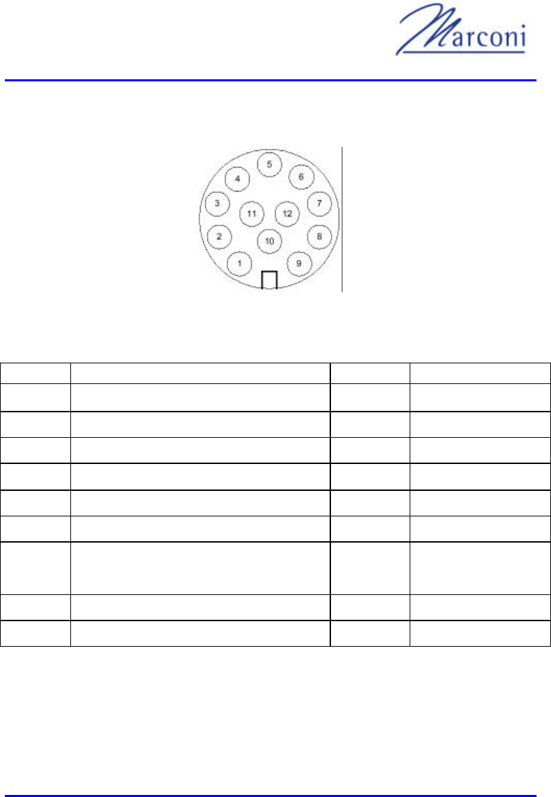
All connections are made through a single 12-conductor cable. Pin numbers and
signals are shown in Figure 5-3 and Table 5-1.
Figure 5-3: GPS Connector View from the Underside
Table 5-1: GPS Connections
GPS pin GPS pin name Cable colour BSDU pin BSDU lead
1 POWER Red 9
2 RX_DATA_1- Blue TD+ (After R5)
3 RX_DATA_1+ Black TD-
4 TX_DATA_1- Yellow 4 RD-
5 TX_DATA_1+ Black RD+ (After R3)
6 RX_DATA_2- Brown x
7 RX_DATA_2+ Black x
9 GND Black 10
11 1PPS+ Green 8 1PPS-
12 1PPS- Black 71PPS+ (After R7)

WipLL System Description
5-8 of 5-8 Marconi Communications Ltd. MCIL -WIPLL-SDN_R2_00
This page intentionally left blank
MCIL -WIPLL-SDN_R2_00 Marconi Communications Ltd. 6-1 of 6-12
SPRSPR
6.1. Subscriber Premises Radio
The subscriber site typically includes a Subscriber Premises Radio (SPR) and a
Subscriber Data Adapter (SDA).
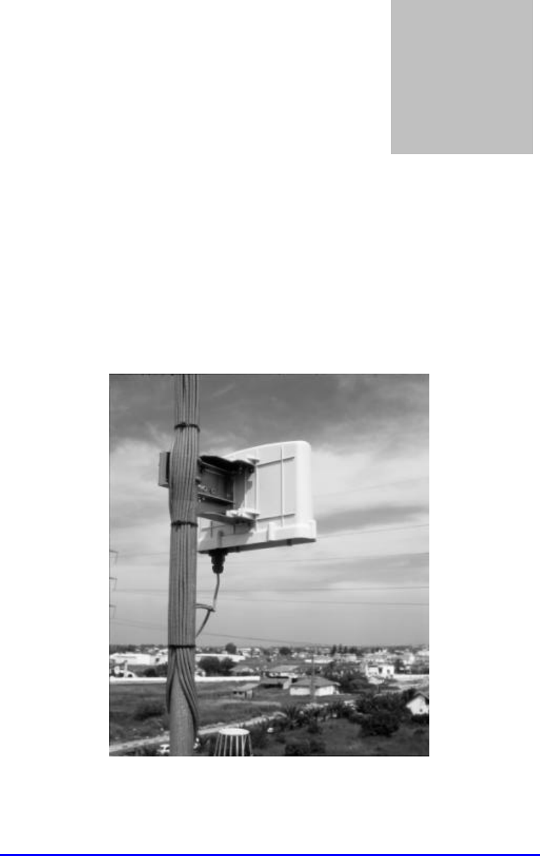
Figure 6-1 shows a typical SPR installation.
Figure 6-1: Typical SPR Installation
Chapter
6
WipLL System Description
6-2 of 6-12 Marconi Communications Ltd. MCIL -WIPLL-SDN_R2_00
SPR Subscriber
Adapter
Video
Conferencing
Figure 6-2: Typical Subscriber Site
6.2. SPR/BSR Communications
The SPR transmits and receives data to and from the base station. It is typically
located on the roof or external wall of the subscriber premises. The SPR has the
reference number of the Base Station Radio (BSR) coded into it. This prevents the
SPR from being removed and placed at a different location without authorisation.
The SPR contains a high-gain directional antenna. The standard 2.4Ghz model
covers an area of 23 degrees with a gain of 15dBi
At the network layer, the SPR performs routing functions between the subscriber's
Ethernet network and the wireless network and contains a routing table that can
support up to 16 entries.
The transport layer of the SPR makes decisions on how to support an application in
terms of bandwidth, delays and mode of operation. There are two modes of
operation - pre-emptive polling and Time Division Multiple Access (TDMA). The
BSR's admission control makes the decision on which mode each unit of the cell
will operate at a given moment.
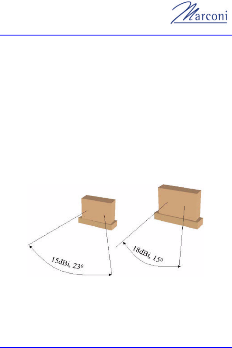
Chapter 6 - SPR
MCIL -WIPLL-SDN_R2_00 Marconi Communications Ltd. 6-3 of 6-12
The SPR is connected to the wired network through an SDA or SDTA supplied with
WipLL Release 1.4, with a 10Base-T Ethernet connection which allows a cable
length of up to 100 meters. The capacity of each SPR is up to 4Mbps.
6.2.1. SPR Configurations
Different versions of the SPR are available. Options include different mechanical,
memory and antenna beam span configurations.
6.2.2. SPR Options
• Standard SPR - an SPR with basic functionality.
• SPR with high gain antenna includes an 18dBi antenna with a sharper beam.
(Not for use in North America, only for ETSI countries).
This option requires a larger box.
Figure 6-3: SPR Options

WipLL System Description
6-4 of 6-12 Marconi Communications Ltd. MCIL -WIPLL-SDN_R2_00
6.2.3. SPR Standard Accessories
• Mechanical mounting brackets - for mounting the units on a wall.
• DB15 connector for the data port with waterproof cover.
6.2.4. Network Management
• MIB - standard MIBs - Ethernet, router
• Marconi proprietary

Chapter 6 - SPR
MCIL -WIPLL-SDN_R2_00 Marconi Communications Ltd. 6-5 of 6-12
6.2.5. Capabilities
• Configuration - network parameters (IP address, ports, routing tables, etc.), RF
parameters (frequency tables, allowed BSRs, etc.).
• Traps - send traps as per configuration.
• Fault management - debugging options.
• Statistical counters - for packet loss, etc.
6.2.6. Physical Interfaces
6.2.6.1. Connectors:
• DB15 - power, Ethernet and serial.
• DB9 - serial interface.
6.2.6.2. Communication Interfaces:
• Ethernet - 10 Mbps.
• Serial - RS-232.
6.2.7. Features and Protocols
6.2.7.1. Features
• Software upgrade - with TFTP.
• Static routing tables - 16 entries per Ethernet port.

WipLL System Description
6-6 of 6-12 Marconi Communications Ltd. MCIL -WIPLL-SDN_R2_00
• QoS - Proprietary.
• Network management - SNMPv2
• Concurrent open sessions - 50
6.2.7.2. Protocols
• - ARP
• -
• - TFTP
• - ICMP
• - SNMP

Chapter 6 - SPR
MCIL -WIPLL-SDN_R2_00 Marconi Communications Ltd. 6-7 of 6-12
Table 6-1: Radio and MAC Specifications
Parameter Value Comment
Operating frequency
Release 1.2
Release 1.4
2.4 GHz
2.4 GHz
Spectrum spreading method Frequency hopping CDMA Per ETSI EN300 328
Duplexing Method Time Div. Duplex (TDD) 2.4GHz
Transmit Bit Rates Up to 4Mbps BER and distance dependent
Channel spacing 1MHz
Output power from the radio Up to 19dBm, configurable
Effective Isotropic Radiated
Power (EIRP) 34dBm, configurable up to 46dBm Depending on local
regulations maximum output
power can be set at factory
Modulation method 8 level CPFSK
Channel access method PPMA / Adaptive TDMA
Protocol efficiency Up to 80% At BER = 10-5 , depending on
the application
Table 6-2: Agency Certification
Parameter Value Comment
Emissions / Immunity EN 300 339 EN 300 386-2 ETS
300 328
Safety EN/IEC 60950
Environmental ETS 300 019-2-x

WipLL System Description
6-8 of 6-12 Marconi Communications Ltd. MCIL -WIPLL-SDN_R2_00
Table 6-3: Netw ork Specifications
Parameter Value Comment
Filtering rate 10500 frames / sec
Forwarding rate 1300 frames / sec
Routing table length 16
Table 6-4: Power Requirements
Parameter Value Comment
Voltage
Minimum
Maximum
48Vdc nominal
30Vdc
55Vdc
Fed from either the SDA
Consumption Maximum 500mA
Table 6-5: Environmental Considerations
Parameter Value Comment
Operating temperature
Outdoor units
(BSR,SPR)
- Optional range of -
Storage temperature -
Table 6-6: Network Interface
Parameter Value Comment
Ethernet Network UTP EIA / TIA Category 5
Standards Compliance ANSI/IEEE 8 02.3 and ISO/IEC
8802-3 10 Base-T compliant
Serial Port RS-232
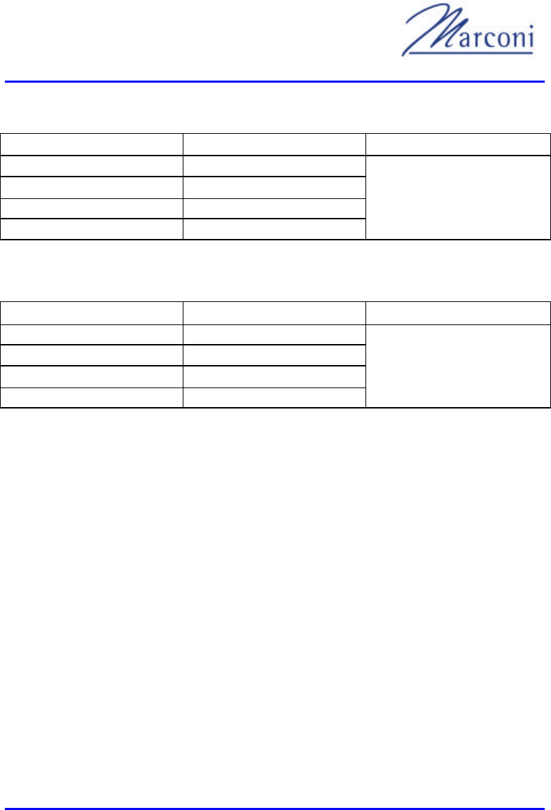
Chapter 6 - SPR
MCIL -WIPLL-SDN_R2_00 Marconi Communications Ltd. 6-9 of 6-12
Table 6-7: SPR Physical Dimensions (w/o High Gain Antenna)
Parameter Value Comment
Height 311mm
Width 244mm
Depth 65.5mm
Weight 2.5kg
Excluding mounting kit
Table 6-8: SPR Physical Dimensions (with High Gain Antenna)
Parameter Value Comment
Height 400mm
Width 317mm
Depth 65.5mm
Weight 4.7kg
Excluding mounting kit
Note: The cable and connector are the same as for the base station.
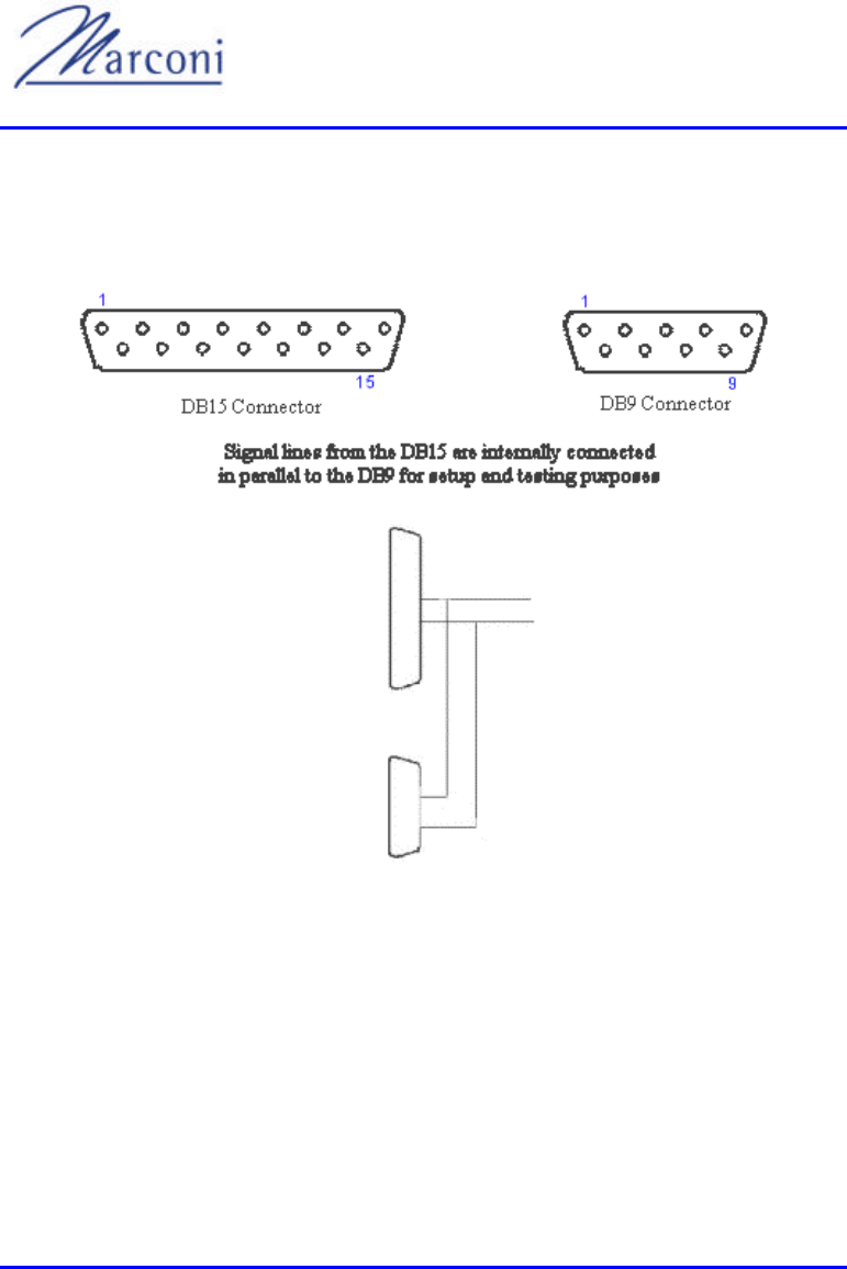
WipLL System Description
6-10 of 6-12 Marconi Communications Ltd. MCIL -WIPLL-SDN_R2_00
6.3. Interface Connectors
Figure 6-4 and Table 6-9 detail the pin configuration for the SPR interfaces.
Figure 6-4: SPR Assembly

Chapter 6 - SPR
MCIL -WIPLL-SDN_R2_00 Marconi Communications Ltd. 6-11 of 6-12
Table 6-9: SPR Connectors
9 Pin Communications Connector 15 Pin Data/Power Connector
1 nc 1 + VIN F
2 Rx 2 - VIN F
3 Tx 3 Ethernet Tx +
4 nc 4 Ethernet Tx -
5 Ground 5 Ethernet Rx +
6 nc 6 Ethernet Rx -
7 Ground 7 nc
8 nc 8 nc
9 +5vDC 9 +VIN F
10 - VIN F
11 VCC
12 GND
13 nc
14 232 Rx
15 232 Tx
The cable run must be mechanically protected and supported at maximum 1 meter
intervals in a 20mm galvanised steel flexible conduit for external runs and in 20mm
PVC conduit for internal runs. Communications output must be in 50mm x 20mm
PVC trunking.

WipLL System Description
6-12 of 6-12 Marconi Communications Ltd. MCIL -WIPLL-SDN_R2_00
This page intentionally left blank

MCIL -WIPLL-SDN_R1_40 Marconi Communications Ltd. 7-1 of 7-8
Customer Interface Customer Interface
AdaptorsAdaptors
7.1. General
WipLL uses Internet Protocol (IP) to communicate between subscribers. Analog
tele
to PSTN signaling by IP Telephony Gateways. WipLL subscriber units contain the
client-side IP Telephony gateway. The PSTN gateway can be located anywhere
within the network.
7.1.1. Configurations
WipLL's subscriber data and telephony adapter is located at the subscriber premises.
The subscriber adapters' job is to interface the WipLL system with the subscriber
premises equipment. It also provides power to the subscriber premises radio (SPR),
which is located outdoors and performs IP routing and transmits and receive data
from the base station, using radio frequencies (RF). Lightning protection is also
done at the subscriber adapter.
There are several configurations for the subscriber adapters that are related mainly to
the interface required by the subscriber and to the configuration of the system.
7.2. SDA
The Subscriber Data Adapter (SDA) is an Ethernet HUB that provides 2 10-BaseT
connections to host computers or a network. It also provides power, lightning
Chapter
7

WipLL System Description
7-2 of 7-8 Marconi Communications Ltd. MCIL -WIPLL-SDN_R1_40
protection and data connection to the SPR. It connects to the main power and
includes LEDs for display of network connection and data traffic.
The SDA box can be wall mounted, in a communications closet or sited on a desk.
7.2.1. SDA Specifications
• Dimensions: 150mm Height x 150mm width x 58.5mm depth
• Weight: .65kg
• Power Consimption: 6 watts (AC)
• Input Voltage: 117-230 Vac 50/60Hz
• Output Voltage: 48Vdc
• Power Capacity: 50 watts (DC)
• Environmental Conditions
• Temperature: -
•
• Connections
• 8-pin connector to SPR or BSR (See Table 7-1, page 7-4)
• RJ45 socket for Ethernet LAN
• RJ45 socket for a PC interface
• Optional accessories
• Wall mounting kit.
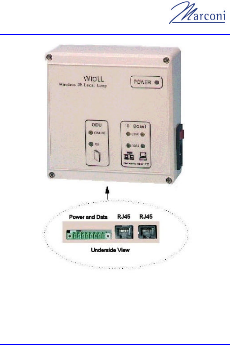
Chapter 7 - Customer Interface Adaptors
MCIL -WIPLL-SDN_R1_40 Marconi Communications Ltd. 7-3 of 7-8
Figure 7-1: Subsc riber Data Adapter (SDA)
The SDA includes lightning arrestors to protect the customer's local network from
lightning. The SDA is connected to a standard power outlet (110-240vAC). The
units are generally installed indoors in a communications cabinet or mounted on a

WipLL System Description
7-4 of 7-8 Marconi Communications Ltd. MCIL -WIPLL-SDN_R1_40
wall. An SDA can also be placed on a table or shelf next to the customer's
communications equipment.
Table 7-1 illustrates the data connector pinouts.
Table 7-1: Data Connections
8-way Connector J3 J2
1 nc 1 +Tx2 1 +Rx3
2 nc 2 -Tx2 2 -Rx3
3 -48v 3 +Rx2 3 +Tx3
4 +48v 4 nc 4 nc
5 -Tx 5 nc 5 nc
6 +Tx 6 -Rx2 6 -Tx3
7 -Rx 7 nc 7 nc
8 +RX 8 nc 8 nc
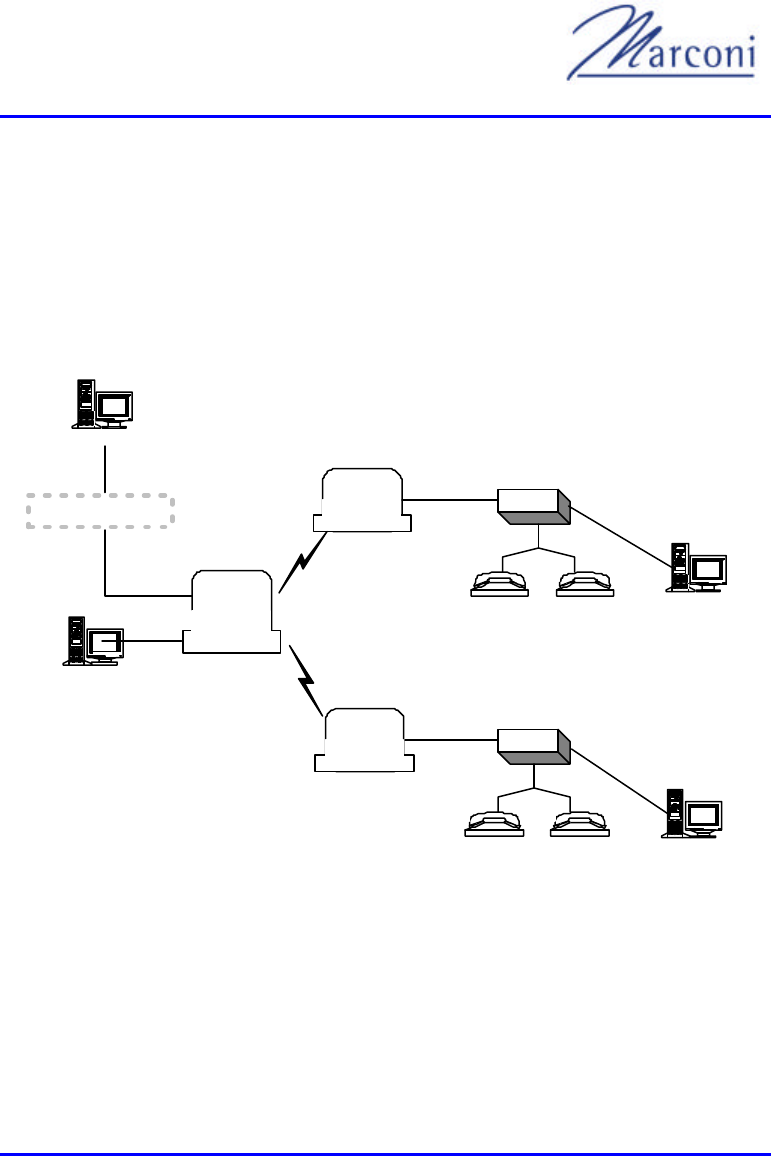
Chapter 7 - Customer Interface Adaptors
MCIL -WIPLL-SDN_R1_40 Marconi Communications Ltd. 7-5 of 7-8
7.3. SDTA
The Subscriber Data and Telephony Adapter (SDTA) is a residential gateway that
telephone lines. It also provides power, lightning protection and data connection to
the SPR. It connects to the main power and includes LEDs for display of network
connection and data traffic.
IBM Compatible
IBM Compatible
SPR
SPR
BSR
SDTA
SDTA
IP Gatekeper
BSDU / LAN / SDA
WipManage
Figure 7-2: VoIP Networking Example
The SDTA box can be wall mounted, in a communications closet or sited on a desk.

WipLL System Description
7-6 of 7-8 Marconi Communications Ltd. MCIL -WIPLL-SDN_R1_40
7.3.1. SDTA Specifications
• Dimensions: 150mm Height x 150mm width x 70mm depth
• Weight: 1.9 Kg
• Power: 40 watts
• Voltage: 48Vdc
• Environmental Conditions
•
•
• Connections
• 2 RJ11 telephone sockets
• Power socket
• DB15 WAN socket
• DB9 serial socket (concealed)
• RJ45 LAN socket
• Accessories
• 48Vdc 750mA power supply
• Wall mounting kit.(optional)
7.3.2. SDTA Interfaces
To SPR:
DB15 connector that includes:
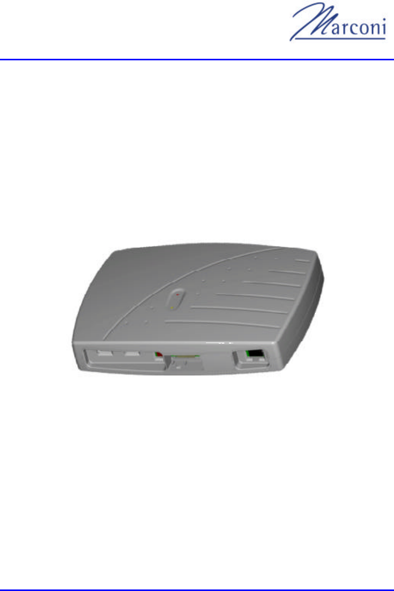
Chapter 7 - Customer Interface Adaptors
MCIL -WIPLL-SDN_R1_40 Marconi Communications Ltd. 7-7 of 7-8
• 10baseT, ANSI/IEEE 802.3
• 48Vdc, 50W
• RJ-11 telephone sockets
To the Ethernet:
• RJ-45 connector
• 10-BaseT, ANSI/IEEE 802.3
Figure 7-3: Subscriber Data and Telephony Adapter (SDTA)
The SDTA includes lightning arrestors to protect the customer's local network from
lightning. The SDTA is connected to a standard power outlet (110-240vAC). Units
are generally installed indoors in a communications cabinet or mounted on a wall.
An SDTA can also be placed on a table or shelf next to the customer's
communications equipment.

WipLL System Description
7-8 of 7-8 Marconi Communications Ltd. MCIL -WIPLL-SDN_R1_40
This page intentionally left blank

MCIL -WIPLL-SDN_R1_40 Marconi Communications Ltd. 8-1 of 8-16
BSPSBSPS
The Marconi Base Station Power System (BSPS) supplies the following:
• Provides off-line power to sensitive equipment
• Charges the battery bank that provides backup power during a mains failure.
Thus, this system is essentially a DC-UPS with a battery connected to it. The
size of the battery determines the backup and charging time. Since the system is
current limited, the maximum battery size is based on that limit.
• Monitors the operation and communicates with a PC or a host to provide full
(remote) control and indication.
Chapter
Chapter
8
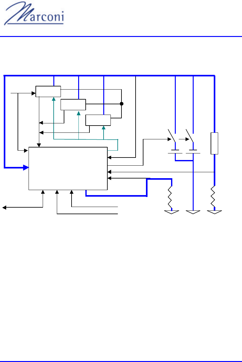
WipLL System Description
8-2 of 8-16 Marconi Communications Ltd. MCIL -WIPLL-SDN_R1_40
8.1. General
I - LOAD
TEMPERATURE
Rectifier
ALARM
-48V
LOAD
LOAD
SHUNT
Rectifier
Rectifier
V-Control
VOUT
I - SUPPLY
MAINS
DRY CONTACT - IN
POWER SYSTEM
CONTROLLER
DUAL -LVD
RS 232
c.sharing
SUPPLY
SHUNT
Figure 8-1: BSPS Block Diagram
As shown in Figure 8-1, 3 rectifiers (or more) are chained in parallel to provide the
current capacity needed. The output voltage of the rectifiers feeds the load and
charges the batteries through the dual LVD.
A dedicated bus that connects all rectifier modules does current sharing.
This is done autonomously and not related to the system controller.
All rectifiers are sharing a voltage control bus (V-CONTROL) by which it is
possible to change the output DC voltage of the system, around the default value of
the modules.
This bus is controlled by the system controller in order to change the output.

Chapter 8 - BSPS
MCIL -WIPLL-SDN_R1_40 Marconi Communications Ltd. 8-3 of 8-16
Another bus (ALARM) sends the information of a faulty rectifier module to the
system controller.
Two accurate shunt-resistors are contained in the system to monitor the load and the
total current.
The battery current is then calculated by the controller to be the difference between
the two.
Two temperature sensors are connected to measure the battery temperature. The
average temperature is calculated and demonstrated.
The status of the various circuit breakers (CB's) is monitored constantly by using
their auxiliary switches. The opening of a CB will result in an audio/visual alarm.
When the reason for alarm is removed, the alarm clears and stops.
8.2. Main Rack
8.2.1. Main Rack
The main rack is the core of the Full-Redundancy 48VDC-power system. It can
contain between one to three rectifiers and a system controller. Listed below are the
components that are housed in the main rack (see Figure 8-2).
• Rectifier modules
• System controller
• LVLD contactors (commanded by the system controller)
• Load and battery circuit breakers for DC protection and distribution
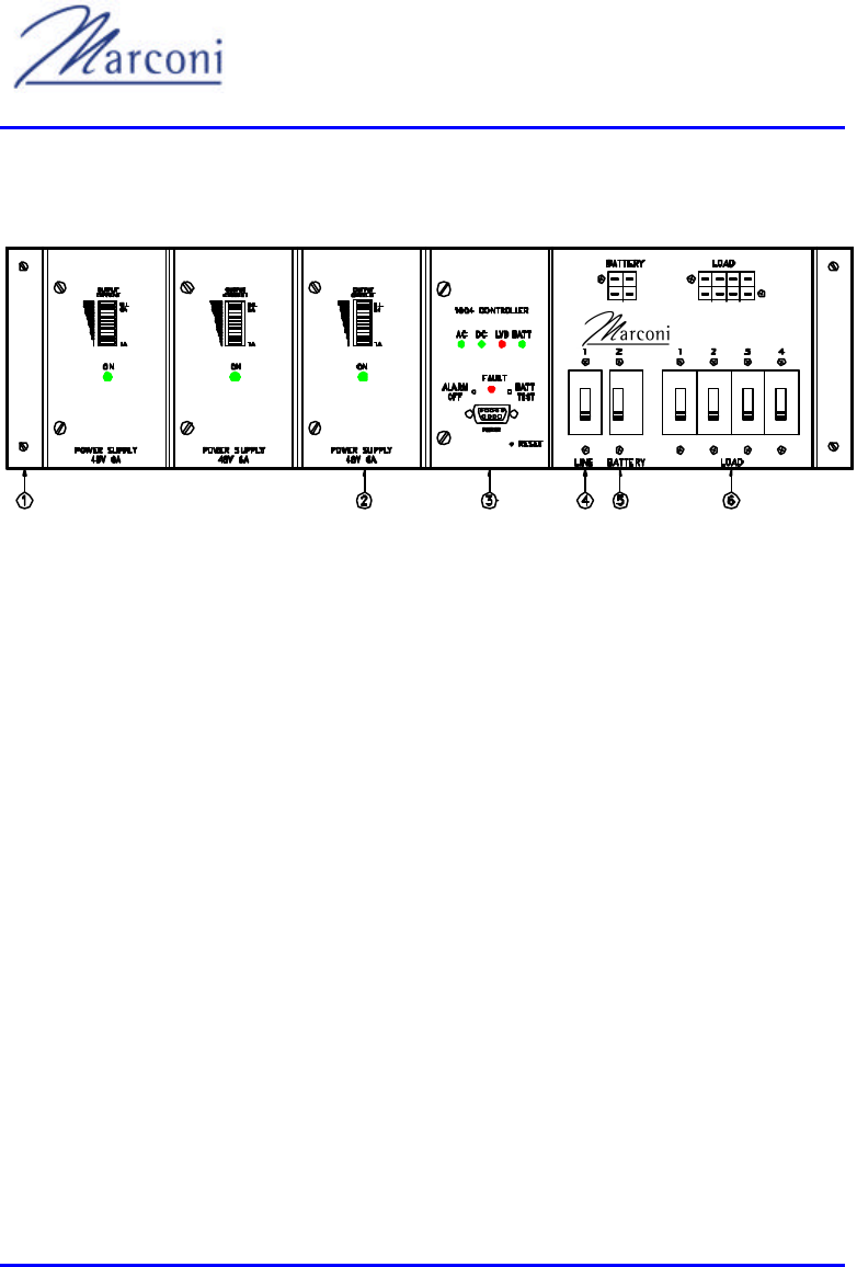
WipLL System Description
8-4 of 8-16 Marconi Communications Ltd. MCIL -WIPLL-SDN_R1_40
8.2.2. Front Panel
Figure 8-2: BSPS Main Rack - Front Panel
The following components are illustrated in Figure 8-3:
1)
2) Rectifier module
3) System controller module
4) Line breaker
5) Battery breaker
6) Load breakers
8.2.3. Rear Panel
The following components are shown in Figure 8-4:
1) LINE IN - AC line input terminations
2) LINE OUT - connection for the extension rack (when exists)
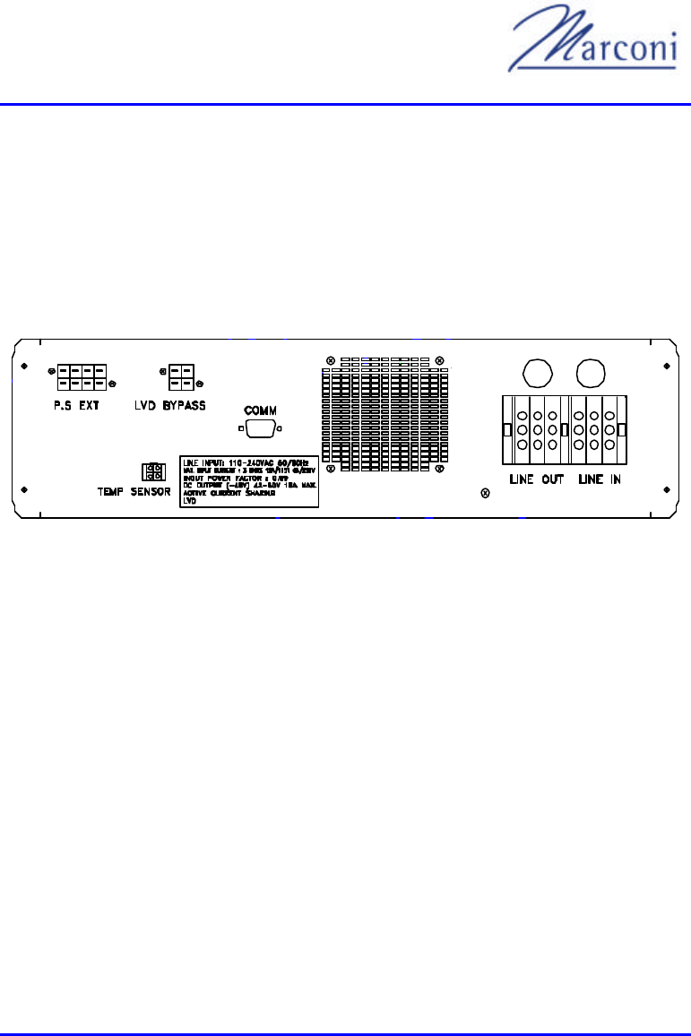
Chapter 8 - BSPS
MCIL -WIPLL-SDN_R1_40 Marconi Communications Ltd. 8-5 of 8-16
3) COMM - data and communication connection for extension rack
4) P.S. EXT - DC connection to the extension rack
5) LVD BYPASS - connection for the DC distribution rack
6) TEMP SENSOR - temperature sensor terminals (four wires)
7) GND - Ground terminal
Figure 8-3: BSPS Main Rack - Rear Panel
8.3. Extension Rack (optional)
8.3.1. Overview
The extension rack is optional and is used only for getting more power from the
system. It can house up to 6 rectifiers. A fully equipped system with the extension
contains 9 rectifiers with a total capability of 54A output current.
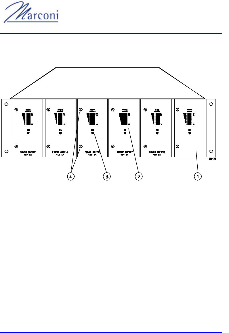
WipLL System Description
8-6 of 8-16 Marconi Communications Ltd. MCIL -WIPLL-SDN_R1_40
8.3.2. Front Panel
Figure 8-4: BSPS Extension Rack - Front Panel
The following are the components illustrated in Figure 8-4:
1) Rectifier module
2) Rectifier load bar graph
3) Rectifier status green LED
4) Rectifier module fasteners
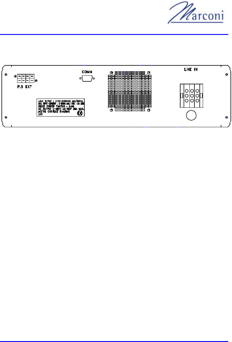
Chapter 8 - BSPS
MCIL -WIPLL-SDN_R1_40 Marconi Communications Ltd. 8-7 of 8-16
8.3.3. Rear Panel
Figure 8-5: BSPS Exte nsion Rack - Rear Panel
The following are the components specified in Figure 8-5:
1) LINE IN - AC line input terminations
2) COMM - data and communication connection to the main rack
3) P.S. EXT - DC connection to the main rack
4) GND - Ground terminal
8.4. DC Distribution Rack (optional)
8.4.1. Overview
This section is optional and provides more circuit -breakers (CB's) for the sake of
distributing the output current to more separate consumers.
This rack contains as well a bypass switch to bypass the LVD.
When this switch is activated the battery is no longer protected against deep
discharge and the system controller alarm will be thus activated.
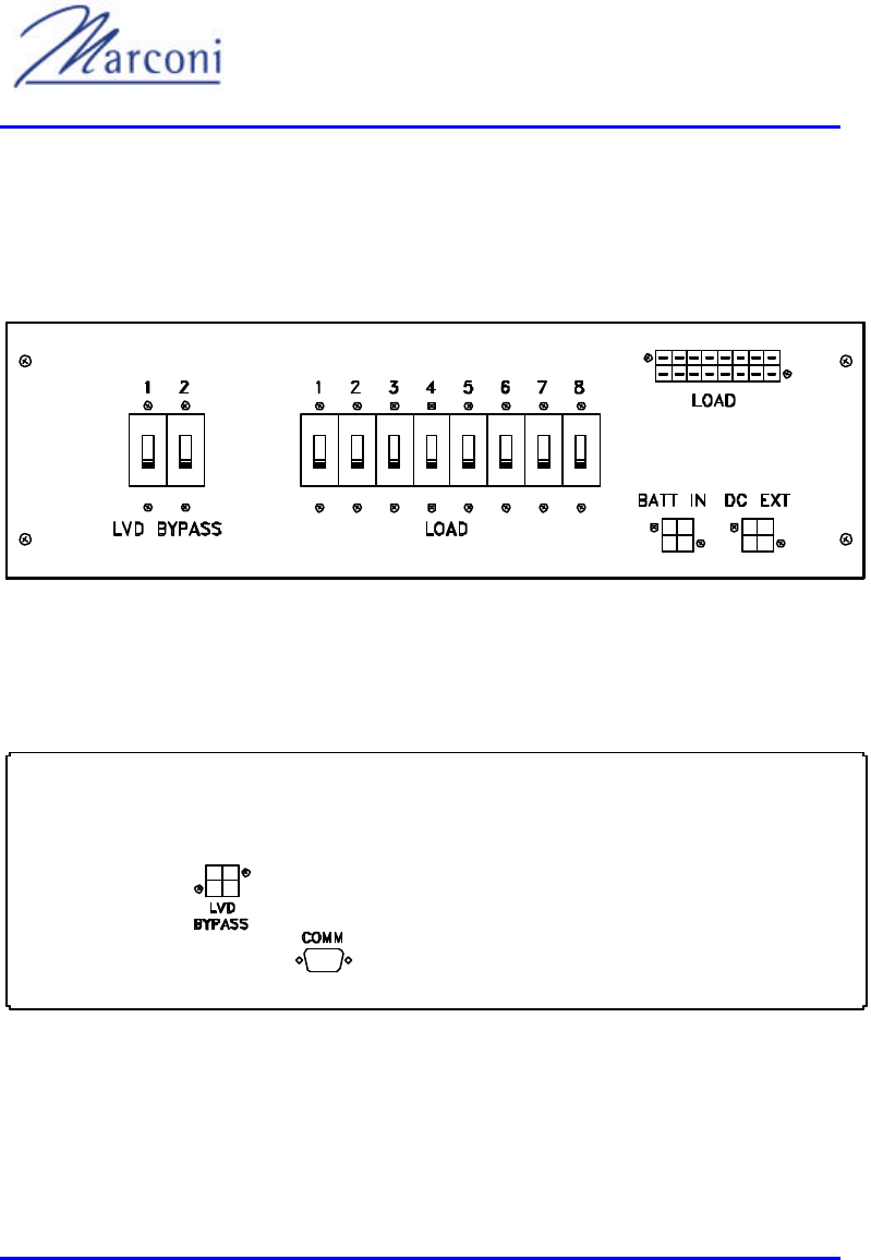
WipLL System Description
8-8 of 8-16 Marconi Communications Ltd. MCIL -WIPLL-SDN_R1_40
The distribution rack also contains the terminations for connecting to other parts of
the system (main and extension racks).
8.4.2. Front Panel
Figure 8-6: BSPS DC Distribution Rack - Front Panel
8.4.3. Rear Panel
Figure 8-7: BSPS DC Distribution Rack - Rear Panel

Chapter 8 - BSPS
MCIL -WIPLL-SDN_R1_40 Marconi Communications Ltd. 8-9 of 8-16
8.5. Basic Rectifier Module
The PFC50-6 rectifier module is the heart of the Full-Redundancy 48VDC power
system. It is a plugged-in module designed specifically for modular systems. The
power factor correction (PFC) device at the input enables clean, stable, sinusoidal
current consumption from the mains. This converter produces a 382VDC output,
which is then converted to the 50V output.
A current sharing circuit is responsible for current sharing among the rectifiers. This
enables each one of the rectifiers to slightly increase its output voltage.
The rectifiers follow the highest output voltage of the rectifiers that are used.
For example:
There are 2 rectifiers in the system, one of the rectifiers has an output voltage that is
greater than that of the other rectifier. The rectifier with the higher output voltage
will become the master and dictate the output voltage of the total system. The
second rectifier raises its voltage slightly until its output current equals the output
current of the master rectifier. Hence, one rectifier in the system is the master and
the other rectifiers are slaves.
When the master rectifier fails to operate, the rectifier with the next highest initial
output automatically becomes the new master of the system.
Note: The sharing mechanism tends to raise th
approximately one-volt of correction is applied to the system.
The output current indication is indicated by the LED bar graph shown on the front
panel (see Figure 8-8). This bar graph is used to verify current sharing operation,
and to indicate the percentage of the full load.
An RFI input filter built into the input stage suppresses the generated noise
travelling to the line.
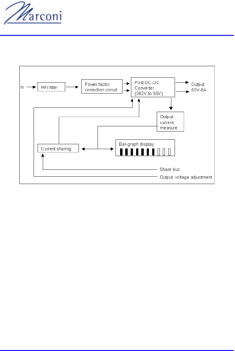
WipLL System Description
8-10 of 8-16 Marconi Communications Ltd. MCIL -WIPLL-SDN_R1_40
8.5.1. Block Diagram
Figure 8-8: BSPS Rectifier - Simplified Block Diagram
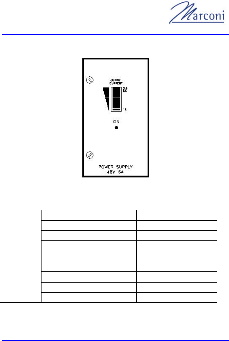
Chapter 8 - BSPS
MCIL -WIPLL-SDN_R1_40 Marconi Communications Ltd. 8-11 of 8-16
8.5.2. Front Panel
Figure 8-9: BSPS Rectifier Module - Front Panel
Table 8-1: Rectifier Specifications
Voltage 90VAC to 270VAC
Current (nominal) 1.6A @ 230V / 3.2A @ 115V
Frequency 47Hz to 63Hz
Power factor (nominal line/load) ≥ 0.993
INPUT
Inrush current (at 25°C ambient) < 65A@230V / 33A@115V
Voltage (default) 53.5VDC
Regulation (line & load) (1) ± 0.4%
Adjustable range 47 to 58 VDC
OUTPUT
Current 6A @ 54V
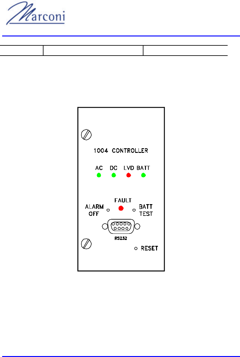
WipLL System Description
8-12 of 8-16 Marconi Communications Ltd. MCIL -WIPLL-SDN_R1_40
Ripple & noise 50mVp -p
8.6. System Controller Module
8.6.1. Front Panel
Figure 8-10: BSPS System Controller - Front Panel
Description:
AC - Input AC voltage is normal (green)
DC - Output DC voltage is normal (green)

Chapter 8 - BSPS
MCIL -WIPLL-SDN_R1_40 Marconi Communications Ltd. 8-13 of 8-16
LVD - Low Voltage Disconnect circuit is open (battery is disconnected, red)
BATT - Battery test passed (green)
FAULT - General alarm fault (red-continuous), Faulty rectifier (red -blinks)
BATT TEST - Manual battery test, use a pencil tip to initiate
ALARM OFF - Silences the internal buzzer, use a pencil tip
RESET - Resetting the controller, use a pencil tip
RS232 - Connector for the host
8.6.2. Main Functions
The 1004 system controller supports these functions:
1) RS232 communication with a host
2) Controlling dual-LVD for managing two branches of batteries. LVD voltages are
settable and nonvolatile
3) Boost/Float charging, voltages are settable and nonvolatile
4) Battery test for two branches
5) Three dry-contacts for alarm, user-defined
6) Audio-visual alarm
7) LED's indicators for AC, DC, LVD, battery and general fault
8) Optional: 2x3 digits display for system voltage/current metering
9) Faulty rectifier detection
10) Open breakers detection (any of them)
11) LVD bypass activation alarm
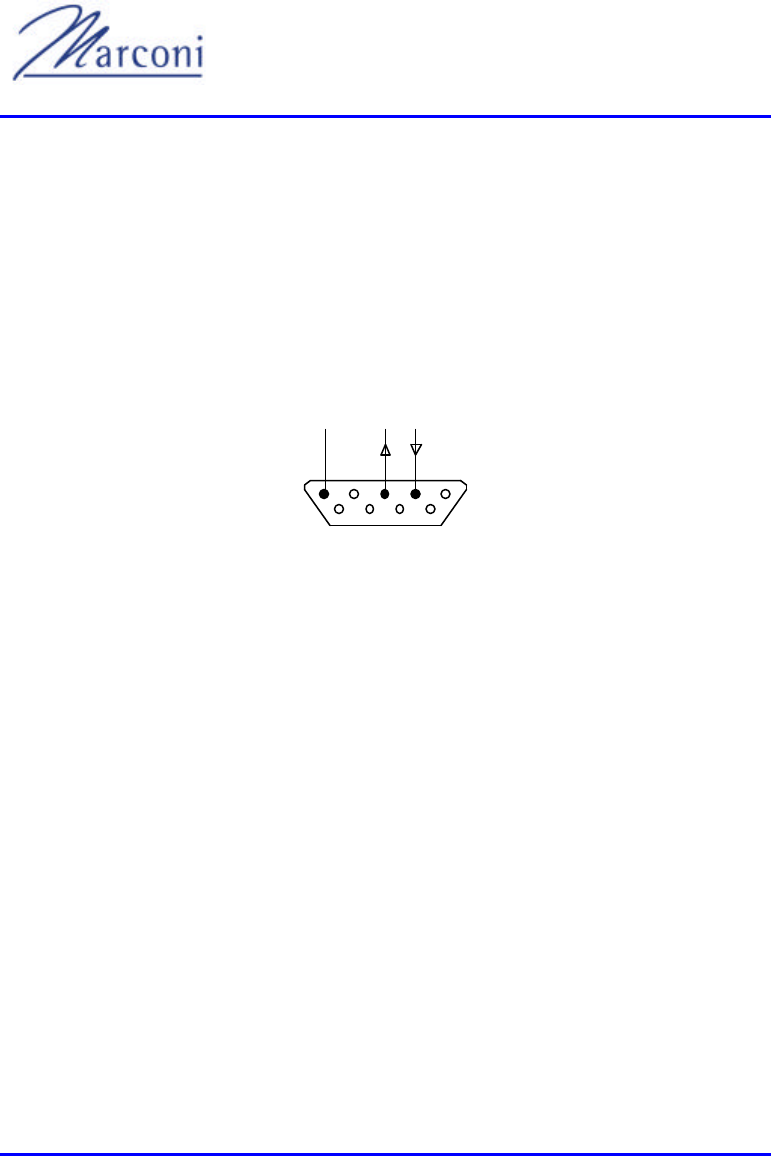
WipLL System Description
8-14 of 8-16 Marconi Communications Ltd. MCIL -WIPLL-SDN_R1_40
12) Abnormal condition detection (AC, DC, battery, over-temperature etc.)
8.6.3. Host Communication
The detailed protocol of communication is described in section 8.7 Communication
Protocol & Data, page 8-14.
The RS232 plug, located at the front panel is used for the connection with the host.
pin assignment for the DB9 connector is as follows:
15
69
RxTxCOM
RS232
Figure 8-11: DB9 Connector
8.7. Communication Protocol & Data
1) The host and the controller communicate in Half-Duplex RS232 9600.N.1 RX,
TX, COM lines, no flow control (neither h/w nor s/w).
2) The HOST is always the MASTER, and the controller is always a slave.
3) Data is binary with no dedicated control chars.
4) Data transmitted by each end has a constant length.
5) There are 3 elements for data reliability: 3 bytes - header.
6) 1 byte - checksum.
7) 3 bytes - termination.
8) Upon reception of a valid packet, the controller will respond in 50mSec as of the
end of the received packet.

Chapter 8 - BSPS
MCIL -WIPLL-SDN_R1_40 Marconi Communications Ltd. 8-15 of 8-16
9) Upon a reception of a header start (0xAC) there will be a start of a reception
window 500mSec long. In case that a valid packet has been received it will be
processed. Otherwise, the controller will initialize the reception counter.
This protocol provides the user with the ability of controlling the power system
parameters as well as retrieving data and status from the system.
8.7.1. Master
The master sends its packet including header, opcode, data, checksum and
termination. The 4-byte opcode bit -combination gives the user the ability to
perform one or more functions at the same time.
The 32-byte data to be sent should include relevant data according to the operation,
set as an opcode by the user.
8.7.2. Slave
The slave responds as soon as a valid packet is received including header, received
opcode, received_checksum, id, data, checksum and termination.
The received_opcode is the last received opcode from the master.
The received_checksum is the last received checksum from the master.
The 4-byte id consists of 3 pre-programmed bytes and an additional byte that can be
programmed by the master.
The 32-byte data always include all the data/status that the user may request,
meaning that every transaction from the master to the slave will always result with
retrieving all possible data that the slave is able to provide.
NOTE: The data retrieved in a transaction does not include the changes made by the
host in its command (if any). Another retrieval should take place in order to get the
valu es that were affected in the previous command.

WipLL System Description
8-16 of 8-16 Marconi Communications Ltd. MCIL -WIPLL-SDN_R1_40
This page intentionally left blank

MCIL -WIPLL-SDN_R1_40 Marconi Communications Ltd. 9-1 of 9-8
AppendixAppendix
9.1. New Features Release 1.4
S/N Feature Remarks
1 3.5 GHz (Not for North America) FDD mode
in addition to 2.4 GHz (TDD)
2 External antenna for BSR (Not for North
America) N-type connector (only for 2.4GHz)
3 GPS for synchronization among Base
Stations (Not for North America) Adapter connects BSDU
for Rev C only
4 BSPS Provides power to the Base Station
5 VoIP (for test & demo):
H.323 based
Only for tests and demos
Works in conjunction with Commatch GW
6 Improved QoS Eight (8) priorities
7 Bandwidth limitations Each SPR may have a max. bit rate
8 SNMP support for BSDU MIB -II and private MIB
Via WipManage
9 IntraCom Traffic among SPRs can be centrally
monitored or not
10 Configuring IP on the air More IP addressing related flexibility of the
network
11 Default confi gurations via WipConfig &
WipManage
12 RSSI analysis in WipConfig
Chapter
9

WipLL System Description
9-2 of 9-8 Marconi Communications Ltd. MCIL -WIPLL-SDN_R1_40
9.2. 3.5 GHz ((Not for North America).
• WipLL now provides a Wireless Local Loop (WLL) solution in the licensed
3.5GHz band, as well as 2.4GHz unlicensed ISM frequency band. Previous
releases supported 2.4GHz only.
• In a point-to -multipoint system, a base station radio communicates with
multiple SPRs, using either Time Division Duplexing (TDD) or Frequency
Division Duplexing (FDD). WipLL release 1.4 now uses FDD mode when
working at 3.5GHz, dividing the available spectrum into two separate
channels, one for upstream the other for downstream.
• 3.5GHz implementation requires new ETSI approved hardware for both the
BSR and SPR.
9.3. External antenna (Not for North America).
• For 2.4GHz, BSRs are now also available with an N-type connector for
attaching an external antenna instead of the internal antenna as in previous
releases.
Figure 9-1: N-Type Connector
• External antenna support makes WipLL more flexible and allows WipLL to
fit different scenarios following special customer requests.
• In order to support an external antenna, new hardware is required for the
BSR. This hardware is ETSI approved.
• The external antenna may have a gain of 5-15dbi. The customer is
responsible to ensure compliance.

Chapter 9 - Appendix
MCIL -WIPLL-SDN_R1_40 Marconi Communications Ltd. 9-3 of 9-8
9.4. GPS for synchronization among Base
Stations (Not for North America)
• In order to synchronize an environment of multiple Base Station Distribution
Units (BSDUs), it is critical that the entire network operates with the same
clock. Base stations are now equipped with a GPS antenna, which receives a
universal satellite clock signal.
• WipLL Release 1.4 includes software modification to the BSDU to support a
GPS.
• A BSDU revision C provides the GPS with 48VDC. However as the GPS
requires a 32VDC supply, a DC/DC convertor is available, which connects t o
the 15 pin connector on the BSDU.
• Release 1.4 now also includes a release for BSDU revisions D and E where
there is no need for the adapter.
9.5. BSPS
• Base Station Power System (BSPS) is released as part of a cabinet, to
provide power to the BSDUs at the base station.
9.6. VoIP
• WipLL now provides a solution for voice and data. However at this stage
voice support is for demos and tests only and is not officially released for
general use.
• WipLL 1.4 voice support includes a Subscriber Data and Telephony Adapter
(SDTA), one of the elements of the latest WipLL solution. The SDTA
provides both voice and data services whereas the SDA provides only data
services. The SDTA also provides a LAN port to connect the local PVC and
2 POTS ports to connect analog telephones.
• The SDTA at release 1.4 supports H.323, G.711, G.723 and G.729 standards.

WipLL System Description
9-4 of 9-8 Marconi Communications Ltd. MCIL -WIPLL-SDN_R1_40
9.7. Improved Quality of Service (QoS)
§ QoS is the ability to recognize the type of transmission and assign optimal
resources accordingly. This is especially important for VoIP applications,
that are sensitive to delay and jitter and should therefore be prioritized over
other applications.
§ QoS is used for packets leaving the SPRs towards the BSR as well as among
SPRs making sure that the BSR assigns the correct priority to the correct
SPR.
§ WipLL 1.4 now provides eight (8) levels of priority: 0 through 7. Priorities
are based on source IP address or ranges of addresses, destination IP address
or ranges of addresses, protocol type (UDP, TCP, ICMP) and TCP/UDP
ports which actually define the applications, such as a WEB application on
port 80).
§ When WipLL identifies a VoIP packet from an analog phone connected to
the SDTA, it automatically provides it with the highest priority value (7).
§ When a packet arrives from the Ethernet network to an SPR, the system
recognizes the type of the packet and assigns it with a Time-To-Live (TTL)
value.
§ TTL determines which packets go first, where packets share the same
priority.
§ Each packet is marked whether critical or not, to determine if it should be
sent when TTL expires or it should be dropped.
§ Higher priority packets always go first regardless of the TTL of lower
priority packets.
9.8. Bandwidth limitations
The BSR receives and transmits data to multiple SPRs. Using WipManage the user
can set the maximum bandwidth values for different SPRs.
With good planning and minimal system congestion, each SPR can use the
maximum defined bandwidth, so long as does not exceed the maximum overall
bandwidth.

Chapter 9 - Appendix
MCIL -WIPLL-SDN_R1_40 Marconi Communications Ltd. 9-5 of 9-8
In a congested network, the real maximum bandwidth for an SPR cannot reach the
defined value, but is still in proportion to the value configured. For example, an SPR
that is set to a maximum of 256Kbps can reach a maximum bandwidth significantly
larger than the maximum standard bandwidth of an SPR set to a 64Kbps.
9.9. SNMP support for BSDU
The BSDU is a major building block in a base station site. As such it is required to
be remotely managed by WipManage. As part of release 1.4, WipManage now
supports the BSDU that has an SNMP agent and supports Management Information
Base II (MIB-II) and private MIB.
9.10. IntraCom
The enabling/disabling IntraCom feature provides an option of controlling the
packets transferred among SPRs with the help of a router or a firewall connected to
the BSR in the base station:
• If IntraCom is allowed, traffic can be routed among the SPRs (via the BSR)
without the involvement of any external router or firewall.
• If IntraCom is not allowed, then traffic among SPRs is routed via the BSR to a
central router or firewall. The central router or firewall controls the traffic. This
capability is often requested by users interested in central control of the traffic
among sites, for reasons such as security.
9.11. Configuring IP on the air
The IP addresses of the air ports of BSRs and SPRs can be configured by the user
Previous releases do not allow this configuration. The IP addresses of the air ports
were fixed IP addresses from the range of 192.168.0.0 .

WipLL System Description
9-6 of 9-8 Marconi Communications Ltd. MCIL -WIPLL-SDN_R1_40
This feature now increases the flexibility of WipLL, permits more efficient use of IP
pre-existing networks. For example a user that uses private IP addresses from the
range of 192.168.0.0 does not have to change IP addresses in the network when
installing WipLL.
9.12. Default configurations via WipConfig &
WipManage
nd installation, release 1.4 provides 2
layers of default configurations for SPRs:
1. Customer defaults located in ROM and loaded during manufacturing. These
parameters are customer specific.
2. Protected parameters basic parameters that enable connectivity of the SPR
such as its IP address, subnet mask and community strings.
Undo operation enables restoring to the previous parameter settings.
9.13. RSSI analysis in WipConfig
WipConfig shows the RSSI value of each SPR. The RSSI value provides important
RF-related information when installing WipLL.
9.14. What is RFC 1918?
Address allocation permits full network layer connectivity among all hosts inside an
enterprise as well as among all public hosts of different enterprises. The cost of
using private internet address space is the potentially costly effort to renumber hosts
and networks between public a nd private.
The industry standard is that whenever possible, users of unregistered (or "dirty")
networks use the reserved addresses in RFC 1918 on any networks inside the
firewall.

Chapter 9 - Appendix
MCIL -WIPLL-SDN_R1_40 Marconi Communications Ltd. 9-7 of 9-8
The RFC 1918 addresses that can be used are:
• Class A: 10.x.x.x
• Class B range: 172.16.0.0 -172.31.0.0
• Class C range: 192.168.1.x-192.168.254.x
The advantages of using these numbers on the inside of the firewall are twofold:
• hout fear of running out of
addresses
•
addresses.
For example, if arbitrarily using the Class C range of 192.31.7.0 for network
addresses on the inside of your firewall, you will find that your computers will never
be able to connect to another machine having a legitimate IP address such as
192.31.7.31, because the hosts will forever be trying to reach a machine on the
inside of your firewall that does not exist.

WipLL System Description
9-8 of 9-8 Marconi Communications Ltd. MCIL -WIPLL-SDN_R1_40
This page intentionally left blank

MCIL-WIPLL-SDN_R1_40 Marconi Communications Ltd. INDEX 1 of 4
INDEX
INDEXINDEX
INDEX
A
Audio/visual alarm, 8-3
B
Base Station, 9-1, 9-3
Distribution Unit, 1-6, 5-1, 9-3
Giving Partial Cover, 1-8
Power System, 9-3
Radio, 1-6, 1-7, 5-1, 6-2
Sector, 1-9
Site, 1-1
Units, 1-6
Basic Rectifier
Front panel of, 8-11
Batteries, 8-2
Battery, 8-1, 8-3, 8-7, 8-13
bank, 8-1
circuit breakers, 8-3
size, 8-1
temperature, 8-3
test, 8-13
manual, 8-13
BSPS
Block Diagram, 8-2
DC Distribution Rack, 8-8
Extension Rack, 8-6, 8-7
Main Rack, 8-4, 8-5
Rectifier, 8-10, 8-11
System Controller, 8-12
BSR Redundancy, 1-8
BSRs
IP addresses of air ports of, 9-5
C
Commatch GW, 9-1
Communication Protocol
8 .8, 8-14
Communications equipment
customer's, 7-4, 7-5
D
DB15 connector, 4-2, 4-4, 5-1, 5-2, 6-
4, 6-5, 7-2, 7-4
DB9 connector, 4-4, 5-2, 6-5, 8-14
DC Distribution Rack, 8-7
E
Ethernet
connection, 1-3
hub, 7-1
network, 9-4
port, 1-11
F
FDD mode, 9-1, 9-2
WipLL System Description
INDEX 2 of 4 Marconi Communications Ltd. MCIL-WIPLL-SDN_R1_40
Firewall, 9-5, 9-6, 9-7
Frequency Division Duplexing, 9-2
Front Panel, 8-4, 8-6, 8-8, 8-11, 8-12
G
GPS
antenna, 9-3
connector view, 5-7
GPS antenna, 9-3
H
Housing development, 1-8
I
Internet address space, 9-6
Internet Protocol, 1-2, 7-1
packets, 2-1
IntraCom feature, 9-5
IP Telephony gateway, 7-1
L
LED bar graph, 8-9
Low Voltage Disconnect circuit, 8-12
M
Maintenance Manual, 1-9
Management Information Base II, 9-5
Management Information Bases
proprietary, 2-5
Marconi Base Station Power System,
8-1
Mbytes/s air link, 1-7
N
Network Operations Center, 1-1
N-type connector, 9-2
O
Opcode, 8-15
P
P.S. EXT, 8-7
Permits full network layer
connectivity
Address allocation, 9-6
PFC50-6 rectifier, 8-9
Pinouts
connector, 7-4, 7-5
Preemptive Polling Multiple Access
protocol, 2-6
Q
Quality of Service functions, 1-4
R
Radio, 1-2, 1-4, 3-2
bandwidth, 4-2
communications, 1-6
frequencies, 7-1

INDEX
MCIL-WIPLL-SDN_R1_40 Marconi Communications Ltd. INDEX 3 of 4
link, 1-2
transceivers, 1-2
Rear Panel, 8-5, 8-7, 8-8
Received_checksum, 8-15
Received_opcode, 8-15
Rectifier, 8-9
Faulty, 8-13
Rectifier load bar graph, 8-6
Rectifier module, 8-3
PFC50-6, 8-9
Rectifier module fasteners, 8-6
Rectifier modules, 8-2
Rectifier Specifications, 8-11
Rectifier status, 8-6
Rectifiers, 8-2, 8-5, 8-9
Release 1.4, 1-1
RFC 1918, 9-6
RFI input filter, 8-9
RJ-11 telephone sockets, 7-4
RJ-45 connector, 7-2, 7-4
RS232 communication, 8-13
RSSI value of each SPR, 9-6
S
Satellite clock signal, 9-3
SDA/SDTA Data Connector Pinouts,
7-6
Settable, 8-13
Simple Network Management
Protocol, 1-3
Simplified Block Diagram, 8-10
Slotted Aloha process, 2-8
SPR
connectivity of, 9-6
SPR set, 9-5
Steel flexible conduit, 6-11
Subscriber Data, 7-4, 9-3
Subscriber Data Adapter, 6-1, 7-1, 7-3
Subscriber Premises, 1-1
Subscriber Premises Equipment, 1-4
Subscriber Premises Radio, 1-10, 2-7,
6-1
T
TCP/UDP ports, 9-4
Telecom
backbone, 1-6
network, 1-2
Telephony
adapter, 7-1, 9-3
Adapter, 7-4, 7-5
service, 2-1
signals, 7-1
Telephony service
toll quality, 1-1
Time Division Duplexing, 9-2
Time Division Multiple Access, 4-1,
6-3
Transceiver, 1-2
Transceivers, 1-2
radio, 1-2
TTL of lower priority packets, 9-4
W
Windows 95, 1-11
Windows NT, 1-10
WipConfig, 9-1

WipLL System Description
INDEX 4 of 4 Marconi Communications Ltd. MCIL-WIPLL-SDN_R1_40
WipConfig & WipManage, 9-6
WipLL
1.4, 9-2, 9-3
voice support, 9-3
broadband cellular wireless system,
1-1
hardware, 1-1
network management tool, 1-10
system, 1-1, 1-4
unit, 1-10, 1-11
WipManage \i, 9-1
Wireless Access system
broadband fixed cellular, 1-1
Wireless Local Loop solution, 9-2