Airspan Networks MMAX2310L WiMAX base station User Manual Air4G Installation Guide
Airspan Networks Inc WiMAX base station Air4G Installation Guide
Users manual

UGD-D00181 Rev G9
Air4G-W24
Installation Guide
System Release 9.5

Air4G-W24 Installation Guide
Page 2 Commercial in Confidence UGD-D00181 Rev G
Copyright
© Copyright by Airspan Networks Inc., 2011. All rights reserved worldwide.
The information contained within this document is proprietary and is subject to all relevant
copyright, patent and other laws protecting intellectual property, as well as any specific
agreements protecting Airspan Networks Inc. rights in the aforesaid information. Neither this
document nor the information contained herein may be published, reproduced or disclosed to
third parties, in whole or in part, without the express, prior, written permission of Airspan Networks
Inc. In addition, any use of this document or the information contained herein for the purposes
other than those for which it is disclosed is strictly forbidden.
Airspan Networks Inc. reserves the right, without prior notice or liability, to make changes in
equipment design or specifications.
Information supplied by Airspan Networks Inc. is believed to be accurate and reliable. However,
no responsibility is assumed by Airspan Networks Inc. for the use thereof nor for the rights of third
parties which may be effected in any way by the use of thereof.
Any representation(s) in this document concerning performance of Airspan Networks Inc.
product(s) are for informational purposes only and are not warranties of future performance, either
expressed or implied. Airspan Networks Inc. standard limited warranty, stated in its sales contract
or order confirmation form, is the only warranty offered by Airspan Networks Inc. in relation
thereto.
This document may contain flaws, omissions or typesetting errors; no warranty is granted nor
liability assumed in relation thereto unless specifically undertaken in Airspan Networks Inc. sales
contract or order confirmation. Information contained herein is periodically updated and changes
will be incorporated into subsequent editions. If you have encountered an error, please notify
Airspan Networks Inc. All specifications are subject to change without prior notice.
Product performance figures quoted within this document are indicative and for information
purposes only.

Air4G-W24 Installation Guide
Page 3 Commercial in Confidence UGD-D00181 Rev G
Table of Contents
Copyright .......................................................................................................................................... 2
Table of Contents ............................................................................................................................. 3
Summary of Figures ......................................................................................................................... 6
Summary of Tables .......................................................................................................................... 8
Warnings and Cautions .................................................................................................................... 9
Human Exposure to Radio Frequencies ...................................................................................... 9
Radio Interference ........................................................................................................................ 9
Avoiding Radio Interference ......................................................................................................... 9
Modifications ................................................................................................................................. 9
General ......................................................................................................................................... 9
Safety ............................................................................................................................................ 9
Warning Symbols........................................................................................................................ 10
Service Information ..................................................................................................................... 10
UL Information ............................................................................................................................ 10
Lightning Protection .................................................................................................................... 11
DECLARATION OF CONFORMITY ............................................................................................... 12
FCC Notice ..................................................................................................................................... 13
Federal Communication Commission Notice ............................................................................. 13
GPS Compliance ........................................................................................................................ 13
Maximum Output TX Power ........................................................................................................... 14
Power Consumption ................................................................................................................... 14
Antenna Types............................................................................................................................ 14
Air4G-W24 Antenna Usage .................................................................................................... 15
1 About this Guide ..................................................................................................................... 18
1.1 Purpose .......................................................................................................................... 18
1.2 Intended Audience .......................................................................................................... 18
1.3 Conventions .................................................................................................................... 18
1.4 Referenced Documentation ............................................................................................ 18
1.5 Organization of this Guide .............................................................................................. 18
2 Introduction ............................................................................................................................. 20
2.1 Air4G-W24 ...................................................................................................................... 20
2.2 Air4G-W24 Frequency Ranges ...................................................................................... 20
2.2.1 Architecture ............................................................................................................. 21
3 Getting Started ........................................................................................................................ 25
3.1 Workflow of Installation ................................................................................................... 25
3.2 Air4G-W24 Installation Checklist .................................................................................... 25
4 Verify Prerequisites................................................................................................................. 26

Air4G-W24 Installation Guide
Page 4 Commercial in Confidence UGD-D00181 Rev G
4.1 Verify Safety Requirements ............................................................................................ 26
4.1.1 Warning of Hazardous Voltages ............................................................................. 26
4.2 Verify Installation Requirements ..................................................................................... 27
4.2.1 Verify the Tools ....................................................................................................... 27
4.2.2 Verify the Parts and Kits ......................................................................................... 27
4.2.3 Verify Components ................................................................................................. 33
5 Install Air4G-W24 .................................................................................................................... 37
5.1 Pole mount configuration ................................................................................................ 37
5.2 Wall mount configuration ................................................................................................ 40
5.2.1 Mounting Examples ................................................................................................ 42
5.3 Air4G-W24 Connections ................................................................................................. 43
5.3.1 LED Display ............................................................................................................ 43
5.4 Install Air4G-W24 Antennas ........................................................................................... 43
5.4.1 Cavity Filter Installation ........................................................................................... 44
5.4.2 Install Dual Slant Antenna ...................................................................................... 45
5.4.3 Install Quad Slant Antenna ..................................................................................... 46
5.4.4 Install Omni Antenna .............................................................................................. 48
5.5 Optional Mounting Antenna on Air4G-W24 .................................................................... 49
5.5.1 Variable Tilt Antenna .............................................................................................. 49
5.6 Cavity Filter Installation................................................................................................... 51
5.7 Antenna Connection ....................................................................................................... 51
5.8 GPS Antenna Assembly ................................................................................................. 53
5.9 LED Display .................................................................................................................... 54
5.10 Install Junction Box (Optional) ........................................................................................ 55
5.10.1 Junction Box Installation ......................................................................................... 55
6 Connect and Manage Cables ................................................................................................. 58
6.1 Assemble Ethernet Connector ........................................................................................ 58
7 Set Power System .................................................................................................................. 59
7.1 Power Input - DC ............................................................................................................ 59
8 Initial WEB Configuration ........................................................................................................ 60
8.1 Initial configuration .......................................................................................................... 60
8.1.1 General Config ........................................................................................................ 60
8.1.2 SNMP Agent/Trap Configuration ............................................................................ 61
8.1.3 Mgmt IP Config ....................................................................................................... 61
8.1.4 BS Operational State .............................................................................................. 62
9 Appendix A ............................................................................................................................. 64
9.1 Review Job Sheet ........................................................................................................... 64
9.2 Securing Fiber-optic Cable ............................................................................................. 64
9.3 Connecting the Fiber-optic Cable ................................................................................... 66

Air4G-W24 Installation Guide
Page 5 Commercial in Confidence UGD-D00181 Rev G
10 Appendix C – Glossary of Terms ........................................................................................ 68
11 Appendix D – Installation Checklist .................................................................................... 70
12 Appendix E ......................................................................................................................... 71
12.1 Revision History .............................................................................................................. 71
12.2 31BContact Information ........................................................................................................ 71

Air4G-W24 Installation Guide
Page 6 Commercial in Confidence UGD-D00181 Rev G
Summary of Figures
Figure 1 – Air4G-W24 – fiber or copper network interface ............................................................. 22
Figure 2 – Air4G-W24 – fiber network interface ............................................................................. 22
Figure 3 - Air4G-W24 – each sector connected separately ........................................................... 23
Figure 4 – Air4G-W24 Functional Components ............................................................................. 24
Figure 5 – Workflow of Installation ................................................................................................. 25
Figure 6 - PS – Air4G-W24 ............................................................................................................. 30
Figure 7 – Air4G-W24 Base Station Unit, Ethernet termination ..................................................... 34
Figure 8 – Air4G-W24 Base Station Unit, RF ports ........................................................................ 34
Figure 9 – Air4G-W24 Cable Assembly for GPS Antenna ............................................................. 35
Figure 10 - Lightning/Surge protector (required) ............................................................................ 35
Figure 11 - Junction box with pole assembly ................................................................................. 36
Figure 12 – Pole Mounted Air4G-W24 Assembly ........................................................................... 37
Figure 13 - pole mounting bracket (2 required) .............................................................................. 37
Figure 14 - pole bracket wrap ......................................................................................................... 38
Figure 15 - position brackets on pole ............................................................................................. 38
Figure 16 - spacing the brackets .................................................................................................... 38
Figure 17 – Pole Mounted Air4G-W24 ........................................................................................... 39
Figure 18 – Wall Mounted Air4G-W24............................................................................................ 40
Figure 19 – Wall Mounted Air4G-W24 Wall Plate Details .............................................................. 41
Figure 20 - Wall mount ................................................................................................................... 42
Figure 21 - GPS alternative assembly ............................................................................................ 42
Figure 22 - Air4G-W24 connections (bottom) ................................................................................. 43
Figure 23 – Air4G-W24 External Antenna Configuration ............................................................... 44
Figure 24 - Cavity filter(s) installation ............................................................................................. 44
Figure 25 - Air4G-W24 Antenna Dual Slant Mast Mount Configuration ......................................... 45
Figure 26 – Air4G-W24 Antenna Quad Slant Mast Mount Configuration....................................... 46
Figure 27 - Adjustable Mounting Kit, with Snaplock Stainless Steel Bands ................................... 47
Figure 28 - Adjustable Mounting Kit, with „V‟ Blocks ...................................................................... 48
Figure 29 - Adjustable Mounting Kit 2, with „V‟ Blocks ................................................................... 48
Figure 30 - possible Omni antenna array ....................................................................................... 48
Figure 31 - Variable tilt antenna ..................................................................................................... 49
Figure 32 - Antenna mounted on Air4G-W24 ................................................................................. 50
Figure 33 - Cavity filter(s) installation ............................................................................................. 51
Figure 34 - Quad port antenna connection – 1 ............................................................................... 52
Figure 35 - Quad port antenna connection – 2 ............................................................................... 53
Figure 36 - GPS cable assembly prior to mounting ........................................................................ 53
Figure 37 - Attach GPS antenna to RG58 cable ............................................................................ 54

Air4G-W24 Installation Guide
Page 7 Commercial in Confidence UGD-D00181 Rev G
Figure 38 - GPS antenna assembled on bracket ........................................................................... 54
Figure 39 - Junction box with mounting brackets assembled ........................................................ 55
Figure 40 - mounting bracket (2 required) ...................................................................................... 55
Figure 41 - Air4G-W24 assembly with optional junction box .......................................................... 57
Figure 42 – Ethernet connector cable termination ......................................................................... 58
Figure 43 – Ethernet environmental connector assembly .............................................................. 58
Figure 44 – DC Power connection.................................................................................................. 59
Figure 45 - Power connector – Air4G-W24 bottom panel .............................................................. 59
Figure 46 – General BS Configuration Initial .................................................................................. 60
Figure 47 - SNMP Initial Configuration ........................................................................................... 61
Figure 48 - Management IP Configuration ..................................................................................... 62
Figure 49 - Operational State ......................................................................................................... 63
Figure 50 - Secure fiber-optic cable, place tie ................................................................................ 65
Figure 51 – Secure fiber-optic cable, pull tie .................................................................................. 65
Figure 52 – Secure fiber-optic cable, snug tie ................................................................................ 65
Figure 53 – Secure fiber-optic cable, cut excess tie....................................................................... 65
Figure 54 – Secure fiber-optic cable, use excess tie...................................................................... 66
Figure 55 – Secure fiber-optic cable, re-use excess tie ................................................................. 66
Figure 56 - fiber-optic connector with dust cover ........................................................................... 66
Figure 57 – dust cover removed ..................................................................................................... 66
Figure 58 - Fiber-Optic Outdoor Connector Plug (multimode) ....................................................... 67
Figure 59 - screw hand-tight ........................................................................................................... 67
Figure 60 - Fiber-optic cable connected ......................................................................................... 67

Air4G-W24 Installation Guide
Page 8 Commercial in Confidence UGD-D00181 Rev G
Summary of Tables
Table 1 - Air4G-W24 FCC Maximum Output TX Power ................................................................. 14
Table 2 - Air4G-W24 ETSI Maximum Output TX Power ................................................................ 14
Table 3 - Power Consumption ........................................................................................................ 14
Table 4 - 700 MHz Antenna Types -Technical ............................................................................... 14
Table 5 - 2.x GHz Antenna Types - Technical ............................................................................... 15
Table 6 - 3.x GHz Antenna Types - Technical ............................................................................... 15
Table 7 - Antenna arrays ................................................................................................................ 16
Table 8 - Air4G-W24 frequency ranges .......................................................................................... 20
Table 9 - Air4G-W24 installation tools ............................................................................................ 27
Table 10 - Air4G-W24 installation parts and kits ............................................................................ 27
Table 11 - Input Power for Air4G-W24 ........................................................................................... 30
Table 12 - Air4G-W24 wall mount installation parts ....................................................................... 31
Table 13 - Air4G-W24 pole mount installation parts ....................................................................... 31
Table 14 - Air4G-W24 additional parts and kits .............................................................................. 31
Table 15 - Cavity filter (for 2.3 variant only) (U.S.A. – WCS market only) ..................................... 32
Table 16 - Junction box (optional) .................................................................................................. 32
Table 17 - Air4G-W24 3.x physical dimensions ............................................................................. 34
Table 18 - Air4G-W24 2.x & 0707 physical dimensions ................................................................. 35
Table 19 - Antenna connection ....................................................................................................... 52
Table 20 - LED Display ................................................................................................................... 54
Table 21 - Cable hole sizes ............................................................................................................ 55
Table 22 - Checklist for Procedure ................................................................................................. 70

Air4G-W24 Installation Guide
Page 9 Commercial in Confidence UGD-D00181 Rev G
Warnings and Cautions
Human Exposure to Radio Frequencies
The Air4G-W24 (formally MacroMAXe) antennas should be installed and operated from a
minimum distance of 2.4 meters (for 3.x & 0707) or 3.4 meters (for 2.x) from your body.
Radio Interference
This Air4G-W24 generates, uses, and can radiate radio frequency energy and, if not installed and
used in accordance with the instructions, may cause harmful interference to radio
communications. However, there is no guarantee that interference will not occur in a particular
installation. If this equipment does cause harmful interference to radio or television reception,
which can be determined by turning the equipment on and off, the technician is encouraged to try
to correct the interference by performing one or more of the following measures:
Re-orientate or relocate the antenna
Increase separation between the BSs and/or End Device
Connect the equipment to an outlet on a circuit different from that to which the power
source is connected
Avoiding Radio Interference
The Air4G-W24 must not be co-located or operating in conjunction with any antenna
or other transmitter.
Ensure a minimum of 1-meter separation between co-located antennas of Air4G-W24
units.
Modifications
Any changes and modifications to this device that are not expressly approved by Airspan
Networks may void the user's authority to operate the equipment.
General
Only qualified personnel should be allowed to install, replace, and service the
equipment.
The device cannot be sold retail, to the general public or by mail order. It must be
sold to operators.
Installation must be controlled.
Installation must be performed by licensed professionals.
Installation requires special training. The Air4G-W24 radio and antenna should be
installed ONLY by experienced installation professionals who are familiar with local
building and safety codes and, wherever applicable, are licensed by the appropriate
government regulatory authorities. Failure to do so may void Airspan's WiMAX
product warranty and may expose the end user or the service provider to legal and
financial liabilities. Airspan and its resellers or distributors are not liable for injury,
damage or violation of regulations associated with the installation of outdoor units or
antennas.
Safety
1. Read this User Manual and follow all operating and safety instructions.
2. Keep all product information for future reference.
3. This product is supplied with a grounding power plug. Do not defeat this important safety
feature.
Air4G-W24 Installation Guide
Page 10 Commercial in Confidence UGD-D00181 Rev G
4. Warning: High voltages exist inside the product - do not remove the lid or base: No user
serviceable parts inside.
5. Position the power cord to avoid possible damage; do not overload wall outlets.
6. Do not place this product on or near a direct heat source, and avoid placing objects on
the terminal.
7. Do not operate this device near water or in a wet location.
8. Use only a damp cloth for cleaning. Do not use liquid or aerosol cleaners. Disconnect
the power before cleaning.
9. The units should not be located near power lines or other electrical power circuits.
10. The radio transceiver must be properly grounded to protect against power surges and
accumulated static electricity. It is the user‟s responsibility to install this device in
accordance with the local electrical codes.
11. Installation of the Air4G-W24 must be contracted to a professional installer.
12. Disconnect Device. The socket outlet should be easily accessible in case you have to
disconnect the device.
13. When installed in the final configuration, the product must comply with the applicable
Safety Standards and regulatory requirements of the country in which it is installed. If
necessary, consult with the appropriate regulatory agencies and inspection authorities to
ensure compliance.
Warning Symbols
The following symbols may be encountered during installation or troubleshooting. These warning
symbols mean danger. Bodily injury may result if you are not aware of the safety hazards involved
in working with electrical equipment and radio transmitters. Familiarize yourself with standard
safety practices before continuing.
Electro-Magnetic Radiation
High Voltage
Service Information
Refer all repairs to qualified service personnel. Do not remove the covers or modify any part
of this device, as this will void the warranty.
Disconnect the power to this product and return it for service if the following conditions apply:
a. The terminal does not function after following the operating instructions outlined
in this manual.
b. Liquid has been spilled, a foreign object is inside, or the terminal has been
exposed to rain.
c. The product has been dropped or the housing is damaged.
Locate the serial number of the terminal, antenna, and transceiver and record these on your
registration card for future reference. Use the space below to affix serial number stickers.
Also record the MAC address, located on the back of the terminal.
UL Information
- The equipment must be properly grounded according with NEC and other local safety code
requirements.
- Reminder to all the BWA system installers: Attention to Section 820-40 of the NEC which
provides guidelines for proper grounding and, in particular, specifies that the cable ground shall

Air4G-W24 Installation Guide
Page 11 Commercial in Confidence UGD-D00181 Rev G
be connected to the grounding system of the building, as close to the point of cable entry as is
practical.
Lightning Protection
WARNING: The following notes are general recommendations for the system. The wireless
equipment should be installed by a qualified professional installer and must follow local and
national codes for electrical grounding and safety. Failure to meet safety requirements and/or use
of non-standard practices and procedures could result in personal injury and damage to
equipment. A direct lightning strike may cause serious damage even if these guidelines are
followed.
All outdoor wireless equipment is susceptible to lightning damage from a direct hit or induced
current from a near strike. Lightning protection and grounding practices in local and national
electrical codes serve to minimize equipment damage, service outages, and serious injury.
Reasons for lightning damage are summarized as:
- Poorly grounded tower/antenna sites that can conduct high lightning strike energy into
equipment.
- Lack of properly installed lightning protection equipment that can cause equipment failures from
lightning induced currents.
A lighting protection system provides a means by which the energy may enter earth without
passing through and damaging parts of a structure. A lightning protection system does not
prevent lightning from striking; it provides a means for controlling it and preventing damage by
providing a low resistance path for the discharge of energy to travel safely to ground. Improperly
grounded connections are also a source of noise that can cause sensitive equipment to
malfunction.
A good tower grounding system disperses most of the surge energy from a tower strike away
from the building and equipment.
To limit the equipment damage due to a lightning strike, the following practices are recommended
for the wireless system:
- Provide direct grounding from the antenna mounting bracket, the radio and antenna and the
lightning arrestors to the same ground point at the base of the tower or a ground bus on the
building. Use the grounding screws on the antenna bracket and the radio and antenna for
terminating the ground wires.
- The AC wall outlet ground must be connected to the same grounding system as the BS.

Air4G-W24 Installation Guide
Page 12 Commercial in Confidence UGD-D00181 Rev G
DECLARATION OF CONFORMITY
European Community, Switzerland, Norway, Iceland, and Liechtenstein
Declaration of Conformity with Regard to the R&TTE Directive 1999/5/EC
English:
This equipment is in compliance with the essential requirements and other relevant provisions of
Directive 1999/5/EC.
Deutsch:
Dieses Gerät entspricht den grundlegenden Anforderungen und den weiteren entsprecheneden
Vorgaben der Richtlinie 1999/5/EU.
Dansk:
Dette udstyr er i overensstemmelse med de væsentlige krav og andre relevante bestemmelser i
Directiv 1999/5/EF.
Español:
Este equipo cumple con los requisitos esenciales asi como con otras disposiciones de la
Directive 1999/5/EC.
Greek:
ΜΕ ΣΗΝ ΠΑΡΟΤΑ Airspan ΔΗΛΩΝΕΙ ΟΣΙ Ο ΕΞΟΠΛΙΜΟ ΤΜΜΟΡΦΩΝΕΣΑΙ ΠΡΟ ΣΙ
ΟΤΙΩΔΕΙ ΑΠΑΙΣΗΕΙ ΚΑΙ ΣΙ ΛΟΙΠΕ ΥΕΣΙΚΕ ΔΙΑΣΑΞΕΙ ΣΗ ΟΔΗΓΙΑ 1999/5/ΕΚ.
Français:
Cet appareil est conforme aux exigencies essentialles et aux autres dispositions pertinantes de la
Directive 1999/5/EC.
Íslenska:
Þessi búnaður samrýmist lögboðnum kröfum og öðrum ákvæðum tilskipunar 1999/5/ESB.
Italiano:
Questo apparato é conforme ai requisiti essenziali ed agli altri principi sanciti dalla Direttiva
1999/5/EC.
Nederlands:
Deze apparatuur voldoet aan de belangrijkste eisen en andere voorzieningen van richtlijn
1999/5/EC.
Norsk:
Dette utstyret er i samsvar med de grunnleggende krav og andre relevante bestemmelser i EU-
directiv 1999/5/EC.
Português:
Este equipamento satisfaz os requisitos essenciais e outras provisões da Directiva 1999/5/EC.
Suomalainen:
Tämä laite täyttää direktiivin 1999/5/EY oleelliset vaatimukset ja on siinä asetettujen muidenkin
ehtojen mukainen.
Svenska:
Denna utrustning är i överensstämmelse med de väsentliga kraven och andra relevanta
bestämmelser i Direktiv 1999/5/EC.
Român:
Acest echipament este în conformitate cu cerinţele esenţiale şi alte prevederi relevante ale
Directivei 1999/5/CE.
The Declaration of Conformity related to this product can be obtained
from 92Hproduct_management@Airspan.com
Air4G-W24 Installation Guide
Page 13 Commercial in Confidence UGD-D00181 Rev G
FCC Notice
Federal Communication Commission Notice
This equipment has been tested and found to comply with the limits for a Class A digital device,
pursuant to part 15 of the FCC Rules. These limits are designed to provide reasonable protection
against harmful interference when the equipment is operated in a commercial environment. This
equipment generates, uses, and can radiate radio frequency energy and, if not installed and used
in accordance with the instruction manual, may cause harmful interference to radio
communications. Operation of this equipment in a residential area is likely to cause harmful
interference in which case the user will be required to correct the interference at his/her own
expense.
Fixed and base stations transmitting a signal with an emission bandwidth greater than 1 MHz
must not exceed an ERP of 1000 watts/MHz and an antenna height of 305 m HAAT, except that
antenna heights greater than 305 m HAAT are permitted if power levels are reduced below 1000
watts/MHz ERP.
GPS Compliance
The GPS is in compliance with the essential requirements and other relevant provisions of
Directive 1999/5/EC."
The GPS complies with the following EMC Common Regulatory Testing standards:
EN55022: Radiated and Conducted Emissions
CISPR 22: Class B
EN 50081-1: Generic Emissions Class B
EN 50082-1: Generic Immunity Class B
EN 61000-4-2: Electrostatic Discharge Immunity
EN 61000-4-3: Radiated RF EM Field Immunity Test
EN 61000-4-4: Electrical Fast Transient/Burst Test
EN 61000-4-6: Conducted Immunity
EN 61000-4-8: Magnetic Field Immunity
Note: A GPS is required for synchronizing between TDD sectors.
Note: A GPS Lightning/Surge protector is required. (ordered separately)
Air4G-W24 Installation Guide
Page 14 Commercial in Confidence UGD-D00181 Rev G
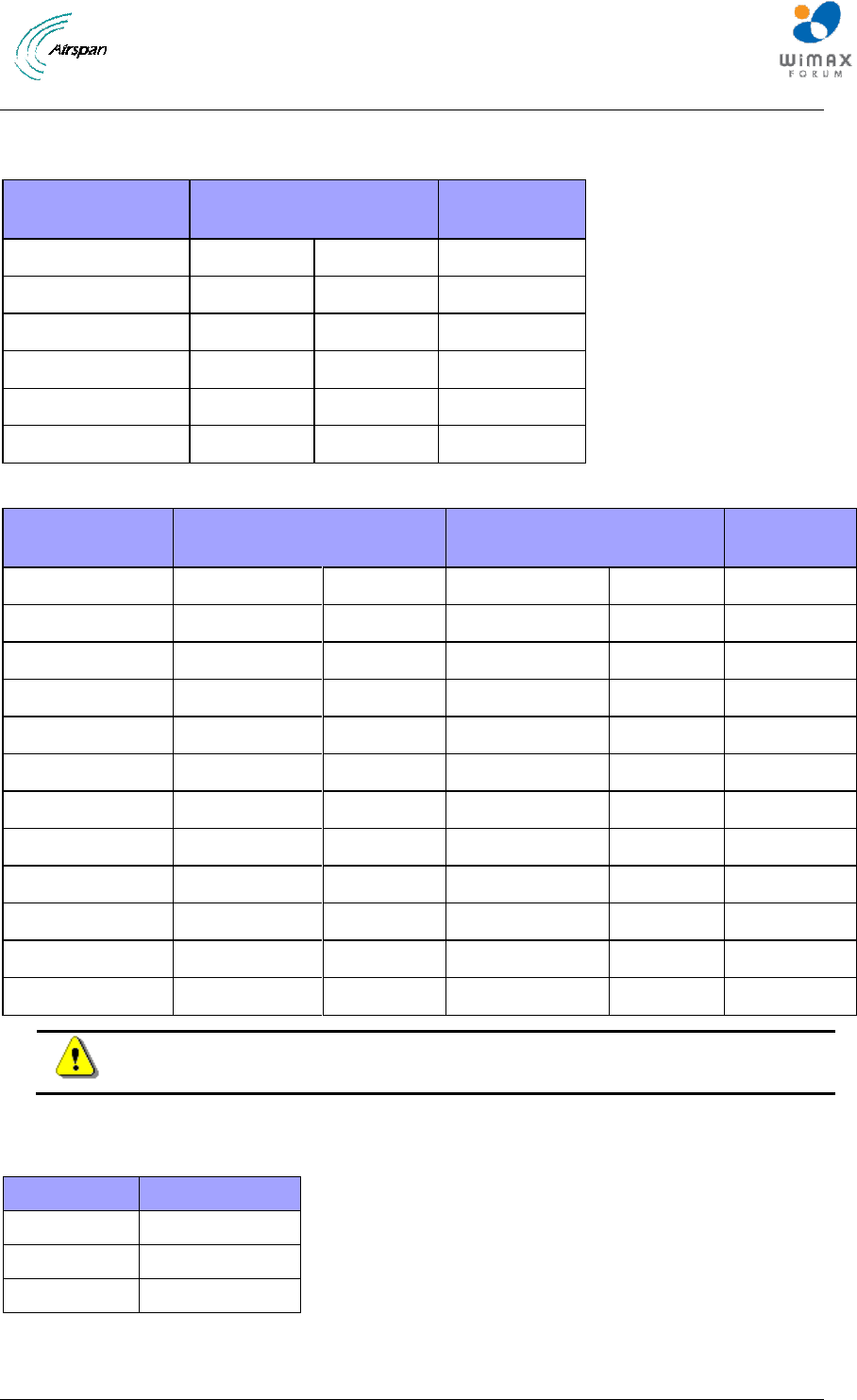
Maximum Output TX Power
Table 1 - Air4G-W24 FCC Maximum Output TX Power
Frequency Band
FCC
TX EIRP
Antenna Gain
700 MHz
41.6 dBm
55.1 dBm
13.5 dBi
2.3 GHz
40.26dBm
58.46dBm
18dBi
2.50 GHz
43.22dBm
61.22dBm
18dBi
2.56 GHz
43.15dBm
61.15dBm
18dBi
2.62 GHz
43.42dBm
61.42dBm
18dBi
3.65 GHz
36.88dBm
38.88dBm
2dBi
Table 2 - Air4G-W24 ETSI Maximum Output TX Power
Frequency Band
ETSI
TX EIRP
Rest of the World
TX EIRP
Antenna Gain
698-746 MHz
41.6 dBm
55.1dBm
41dBm
55dBm
13.5dBi
2290-2350 MHz
43dBm
61dBm
43dBm
61dBm
18.0dBi
2340-2400 MHz
43dBm
61dBm
43dBm
61dBm
18.0dBi
2496-2570 MHz
43dBm
61dBm
43dBm
61dBm
18.0dBi
2560-2630 MHz
43dBM
61dBm
43dBm
61dBm
18.0dBi
2620-2690 MHz
43dBm
61dBm
43dBm
61dBm
18.0dBi
3300-3400 MHz
40dBm
58dBm
40dBm
58dBm
18.0dBi
3400-3500 MHz
40dBm
58dBm
40dBm
58dBm
18.0dBi
3500-3600 MHz
40dBm
58dBm
40dBm
58dBm
18.0dBi
3600-3700 MHz
40dBm
58dBm
40dBm
58dBm
18.0dBi
3650-3675 MHz
40dBm
42dBm
40dBm
42dBm
2dBi
3700-3800 MHz
40dBm
58dBm
40dBm
58dBm
18.0dBi
Caution: Do not set maximum output TX power to higher than local regulations.
Power Consumption
Table 3 - Power Consumption
Air4G-W24
Watts
3.x
230 Max
2.x
370 Max
0707
370 Max
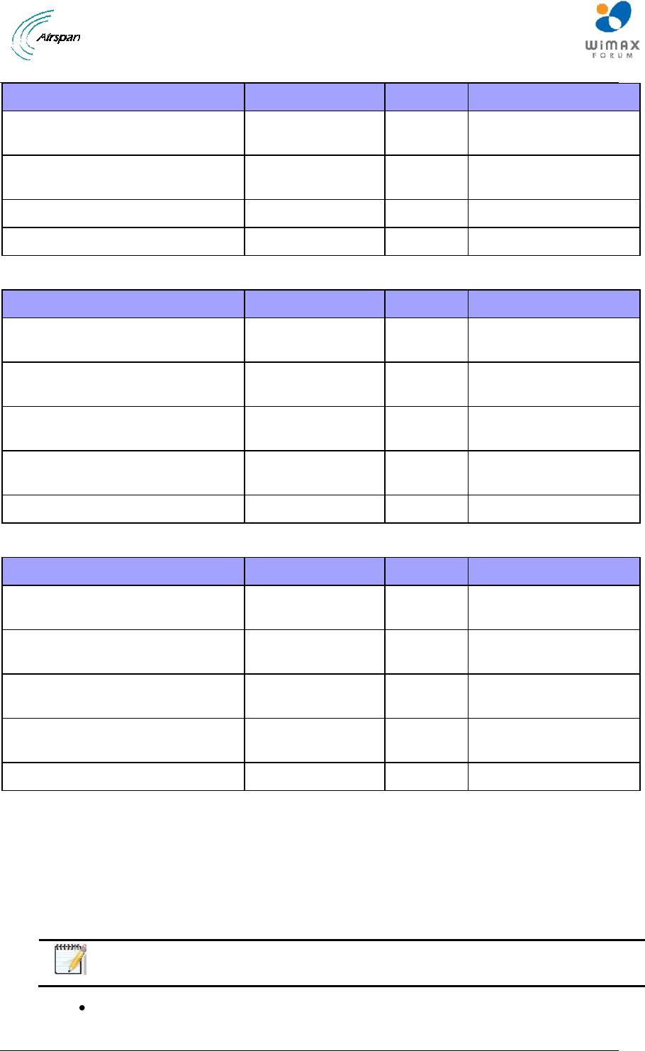
Antenna Types
Table 4 - 700 MHz Antenna Types -Technical
Air4G-W24 Installation Guide
Page 15 Commercial in Confidence UGD-D00181 Rev G
Type
Frequency range
Gain
Part number
60° 13.5 dBi Dual X-Polar –
mounting kit (50 > 115 mm) included
698 - 806 MHz
13.5 dBi
SEC60Q-700-13.5-1
90° 12.5 dBi Dual X-Polar –
mounting kit (50 > 115 mm) included
698 - 806 MHz
12.5 dBi
SEC90Q-700-12.5-1
OMNI Directional
698-746 MHz
6 dBi
MT- NV
OMNI Directional
746-806 MHz
6.5 dBi
MT221023/NV
Table 5 - 2.x GHz Antenna Types - Technical
Type
Frequency range
Gain
Part number
65° Quad X-Polar – mounting kit (50
> 115 mm) included
2.3-2.7 GHz
18.0 dBi
SEC60Q-2.X-RC-1
90° Quad X-Polar – mounting kit (50
> 115 mm) included
2.3-2.7 GHz
17.0 dBi
SEC90Q-2.X-RC-1
60° Dual Slant X-Polar – mounting
kit (50 > 115 mm) included
2.3-2.7 GHz
18.0 dBi
SEC60X-2.X-RC-1
90° Dual Slant X-Polar – mounting
kit (50 > 115 mm) included
2.3-2.7 GHz
17.0 dBi
SEC90X-2.X-RC-1
Omni 10dBi Vertical External
2.3-2.49 GHz
10 dBi
ANT2300OV10-360
Table 6 - 3.x GHz Antenna Types - Technical
Type
Frequency range
Gain
Part number
60° Quad X-Polar – mounting kit (50
> 115 mm) included
3.3 - 3.8 GHz
18.0 dBi
SEC60Q-3.5-RC-1
90° Quad X-Pola – mounting kit (50
> 115 mm) included
3.3 - 3.8 GHz
17.0 dBi
SEC90Q-3.5-RC-1
60° Dual Slant X-Polar – mounting
kit (50 > 115 mm) included
3.3 - 3.8 GHz
18.0 dBi
SEC60X-3.5-RC-1
90° Dual Slant X-Polar – mounting
kit (50 > 115 mm) included
3.3-3.8 GHz
17.0 dBi
SEC90X-3.5-RC-1
Omni Reg Compl Vertical Sector
3.3 – 3.5 GHz
10.0 dBi
OMNIV-3.4-RC-2
Air4G-W24 Antenna Usage
Air4G-W24 has four (4) RF ports that can be connected to either:
A single four-port antenna
Two two-port antennas
Four single-port antennas
Note: Appropriate mounting kit (included) for the dual and quad port
antennas are required.
Quad port cross polarized (X-Pol) antenna with four (4) ports – connected via 4
RF jumper cables to Air4G-W24.

Air4G-W24 Installation Guide
Page 16 Commercial in Confidence UGD-D00181 Rev G
Dual slant cross polarized (X-Pol) antenna with two (2) ports - connected via 2 RF
jumper cables to Air4G-W24.
Omni antennas – for 360 degree coverage using a single Air4G-W24 - requires
an Omni antenna for each receiver – 2 or 4 Omni antennas.
Note: The Omni antennas must be separated – with at least one meter
separation from each other (in 2.X and in 3.X GHz). Additional separation for
700 MHz.
Fixed tilt dual/quad port antennas (where the tilt is set by the way the mounting kit
is installed).
Note: Required mounting kits for fixed tilt dual/quad port antennas are
included.
Manual Electric Tilt (MET) dual/quad antennas - a variable tilt antenna available
for mounting directly on the Air4G-W24 with no need for physical tilting of the
antenna.
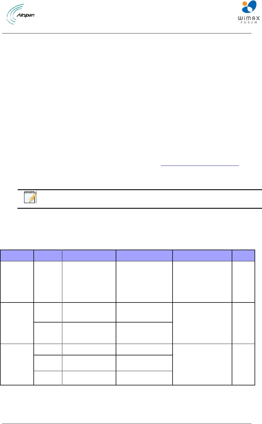
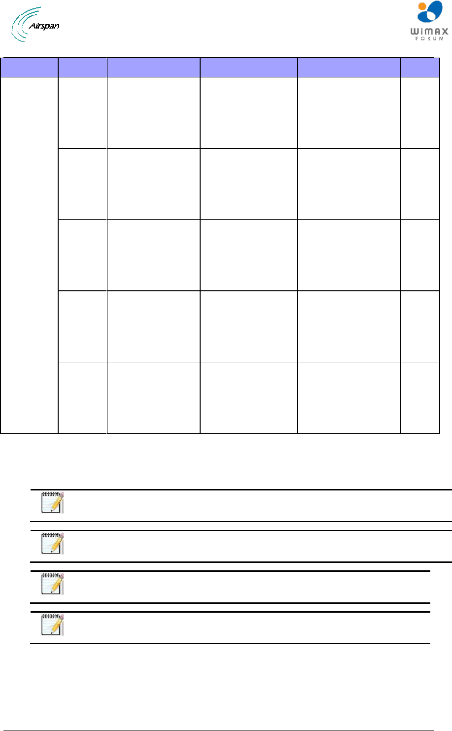
The following table describes different antenna arrays when using either two (2) receivers or four
(4) receivers:
Table 7 - Antenna arrays
Frequency Band
# of Receivers
Sector
Antenna Type
# of Antennas
700 MHz
2
60º
698 - 806 MHz 60º 13.5 dBi
Dual X-Polar
1
700 MHz
4
60º
698 - 806 MHz 60º 13.5 dBi
Dual X-Polar
2
2.3 GHz
2
65º
2.3-2.7 GHz 60º Dual Slant X-
Polar
1
2.3 GHz
4
65º
2.3-2.7 GHz 60º Quad X-Polar
1
2.5 GHz
2
65º
2.3-2.7 GHz 60º Dual Slant X-
Polar Antenna
1
2.5 GHz
4
65º
2.3-2.7 GHz 60º Quad X-Polar
1
3.3-3.8 GHz
2
65º
3.3-3.8 GHz 60º Dual Slant X-
Polar
1
3.3-3.8 GHz
4
65º
3.3-3.8 GHz 60° Quad X-Polar
1
700 MHz
2
90º
698 - 806 MHz 90° 12.5 dBi
Dual X-Polar
1
700 MHz
4
90º
698 - 806 MHz 90° 12.5 dBi
Dual X-Polar
2
2.3 GHz
2
90º
2.3-2.7 GHz 90° Dual Slant X-
Polar
1
2.3 GHz
4
90º
2.3-2.7 GHz 90° Quad X-Polar
1
2.5 GHz
2
90º
2.3-2.7 GHz 90° Dual Slant X-
Polar
1
2.5 GHz
4
90º
2.3-2.7 GHz 90° Quad X-Polar
1
3.3-3.8 GHz
2
90º
3.3-3.8 GHz 90° Dual Slant X-
Polar
1
Air4G-W24 Installation Guide
Page 17 Commercial in Confidence UGD-D00181 Rev G
3.3-3.8 GHz
4
90º
3.3-3.8 GHz 90° Quad X-Polar
1
700 MHz
2
360º
698-746 MHz Omni 5dB/7dBi
Vertical External Antenna
2
700 MHz
4
360º
698-746 MHz Omni 5dB/7dBi
Vertical External Antenna
4
2.3 GHz
2
360º
2.3-2.49 GHz Omni 10 dBi
Vertical External Antenna
2
2.3 GHz
4
360º
2.3-2.49 GHz Omni 10 dBi
Vertical External Antenna
4
2.5 GHz
2
360º
Generic Omni
2
2.5 GHz
4
360º
Generic Omni
4
3.3-3.4 GHz
2
360º
3.3-3.5 GHz Omni Reg Compl
Vertical Sector
2
3.3-3.4 GHz
4
360º
3.3-3.5 GHz Omni Reg Compl
Vertical Sector
4
3.4-3.6 GHz
2
360º
3.4-3.6 GHz Omni Reg Compl
Vertical Sector
2
3.4-3.6 GHz
4
360º
3.4-3.6 GHz Omni Reg Compl
Vertical Sector
4
3.6-3.8 GHz
2
360º
3.6-3.8 GHz Omni Reg Compl
Vertical Sector
2
3.6-3.8 GHz
4
360º
3.6-3.8 GHz Omni Reg Compl
Vertical Sector
4
Air4G-W24 Installation Guide
Page 18 Commercial in Confidence UGD-D00181 Rev G
1 About this Guide
This section discusses the purpose, intended audience, conventions, referenced documentation
and organization for this guide.
1.1 Purpose
This guide provides the workflow and step-by-step procedures for Installing the Air4G-W24
(formally MacroMAXe). These procedures include:
Verify Prerequisites
Install the Air4G-W24
Connect and Manage Cables
Set Power System
1.2 Intended Audience
This guide is intended for persons who are responsible for Installing the Air4G-W24. These
persons should have a working knowledge of the WiMAX system.
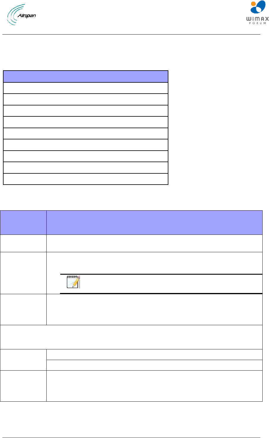
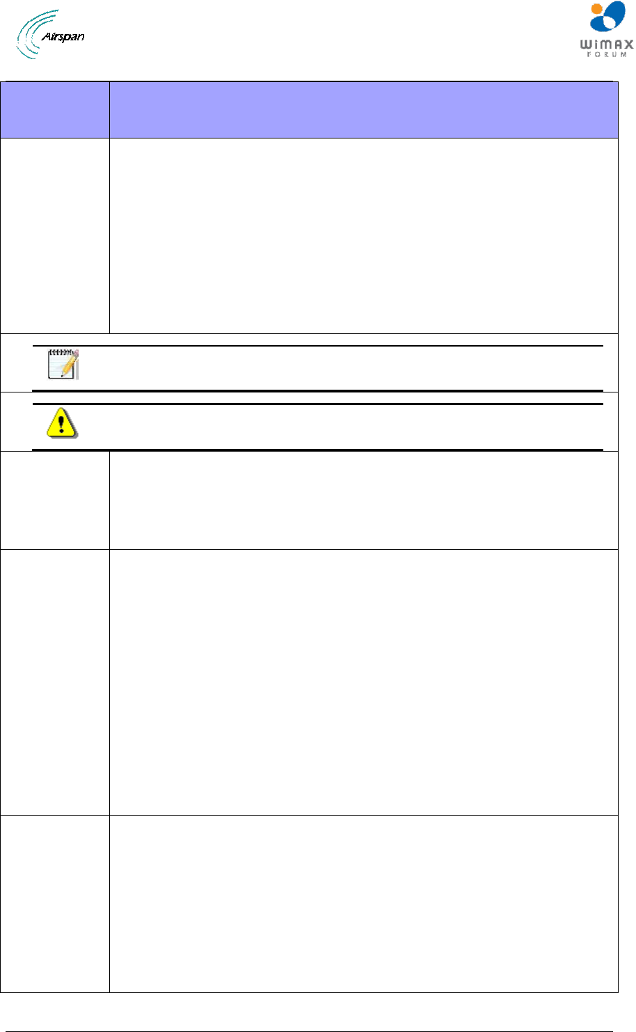
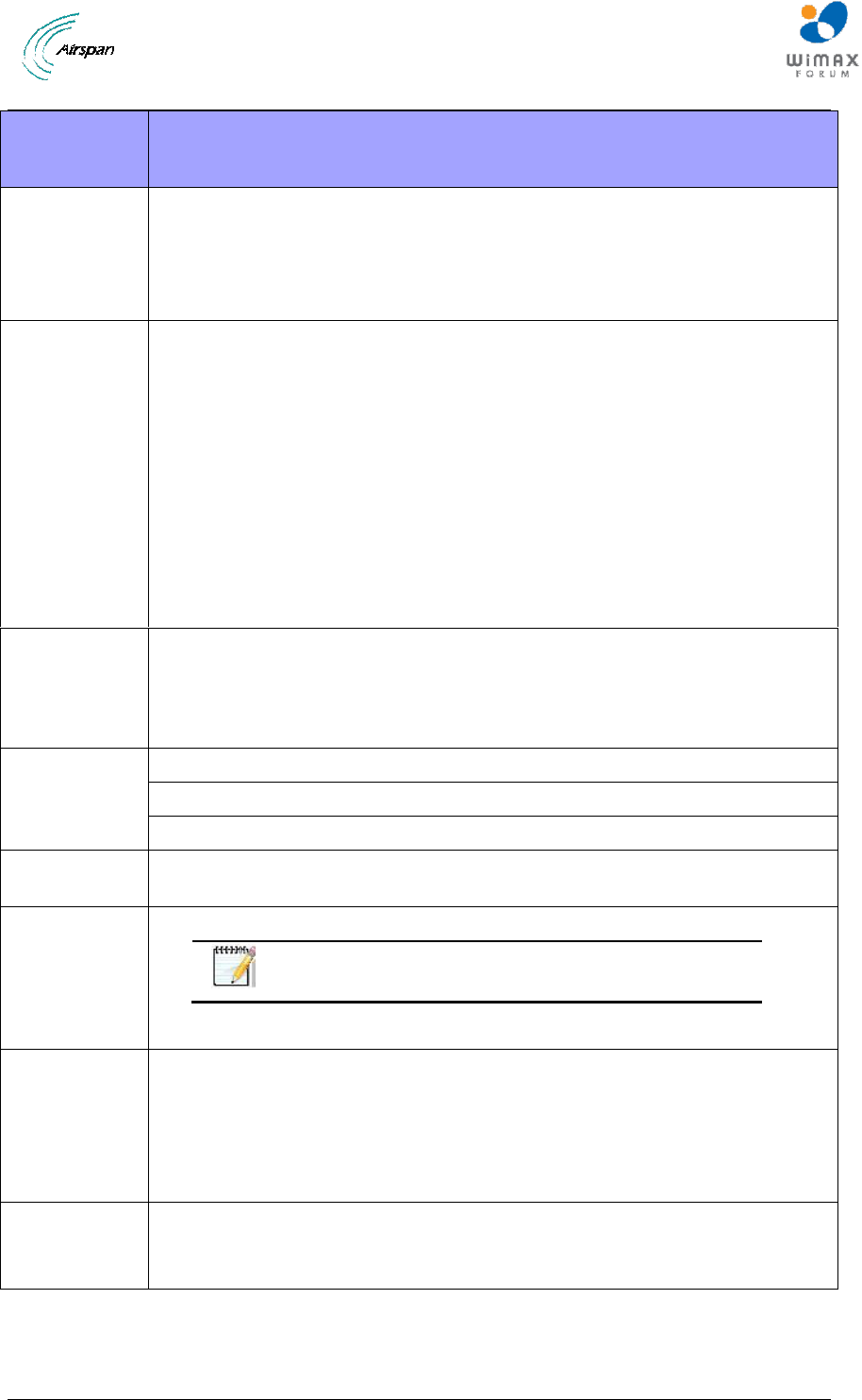
1.3 Conventions
This document uses the following informational conventions.
Icon
Description
Checkpoint: Marks a point in the workflow where there may be an exit or branch
to some other procedure. At each Checkpoint the reason for an exit or branch is
given along with specific directions to locate the entry point in the other
procedure.
Reference: Gives a resource in the workflow that may be needed to complete a
procedure along with specific directions to use the resource.
Caution: Describes a possible risk and how to lessen or avoid the risk.
Advice: Provides a recommendation based on best practice.
Note: Provides useful information.
1.4 Referenced Documentation
Air4G-W24 Product Description
1.5 Organization of this Guide
This guide is organized into the following Sections:
About this Guide
Introduction
Get Started
Verify Prerequisites
Install the Air4G-W24
Connect and Manage Cables

Air4G-W24 Installation Guide
Page 19 Commercial in Confidence UGD-D00181 Rev G
Set Power System
Appendixes [Review Job Sheet, Securing & Connecting the Fiber-Optic cable, Glossary
of Terms, Installation Checklist, Contact information and Revision history]
Air4G-W24 Installation Guide
Page 20 Commercial in Confidence UGD-D00181 Rev G
2 Introduction
This section provides a descriptive overview of the Air4G-W24 (formally MacroMAXe) (3.x, 2.x
and 0707) and its place in the product suite.
2.1 Air4G-W24
Air4G-W24 is a highly integrated macro-cell base station with all-in-one packaging of RF and
baseband components. Air4G-W24 includes integrated quad RF transceivers to support four
channel diversity and MIMO. It is available as an all outdoor solution for Mobile WiMAX
applications to minimize physical footprint and operator OPEX.
Air4G-W24 fully supports the interoperable R6 reference point for interworking with ASN
Gateways. Air4G-W24 also has a “Stand Alone” mode for fixed/nomadic applications which do not
require seamless handover. When Air4G-W24 is used in “Stand Alone” mode there is no need for
an ASN Gateway. Air4G-W24 supports IP CS and Ethernet CS. It even supports a hybrid mode
where both IP CS and Ethernet CS (including VLAN support) are supported. Air4G-W24
implements dual 40dBm (10W) transmitters in 2.x GHz, dual 38 dBm (6.3W) in 700 MHz and dual
37dBm (5W) transmitters in 3.x GHz band.
Air4G-W24 is an outdoor radio that is mounted outside on a pole or wall. Air4G-W24 is available
in numerous frequency bands and in numerous channels see: Air4G-W24 Frequency Ranges.
Air4G-W24 is managed by an SNMP-based network management system (Netspan) using
standard and proprietary MIBs. Basic management can be performed using any standard Web
browser.
Note: For management refer to Air4G-W24 Commissioning documentation.
2.2 Air4G-W24 Frequency Ranges
The table below lists the frequency range of Air4G-W24 variants currently available. This table will
grow as more variants become available.
Table 8 - Air4G-W24 frequency ranges
Band
Variant
Lower Frequency
Upper Frequency
Channel Bandwidth
Duplex
700 MHz
0707
698 MHz
746 MHz
3.5MHz
5MHz
7MHz
10MHz
TDD
2.3 GHz
2310 Lo
(WCS)
2290 MHz
2350 MHz
3.5MHz
5MHz
7MHz
10MHz
TDD
2310 Hi
2340 MHz
2400 MHz
2.5 GHz
2510 Lo
2496 MHZ
2570 MHz
3.5MHz
5MHz
7MHz
10MHz
TDD
2510 Mid
2560 MHz
2630 MHz
2510 Hi
2620 MHz
2690 MHz
Air4G-W24 Installation Guide
Page 21 Commercial in Confidence UGD-D00181 Rev G
Band
Variant
Lower Frequency
Upper Frequency
Channel Bandwidth
Duplex
3.x GHZ
3305
3300 MHZ
3400 MHz
3.5MHz
5MHz
7MHz
10MHz
TDD
3405
3400 MHz
3500 MHz
3.5MHz
5MHz
7MHz
10MHz
TDD
3505
3500 MHz
3600 MHz
3.5MHz
5MHz
7MHz
10MHz
TDD
3605
3600 MHz
3700 MHz
3.5MHz
5MHz
7MHz
10MHz
TDD
3705
3700 MHz
3800 MHz
3.5MHz
5MHz
7MHz
10MHz
TDD
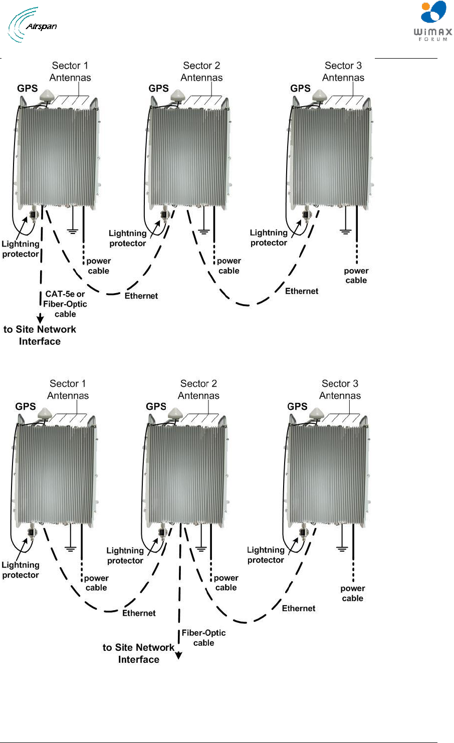
2.2.1 Architecture
A highly flexible and scalable WiMAX Base Station, the Air4G-W24 is capable of supporting
Mobile WiMAX profiles across multiple frequency bands.
Note: The following is for illustration only; actual layout may differ as
infrastructure is installation-specific.
Note: Air4G-W24 must be properly grounded according with NEC and other local
safety code requirements.
Note: Installation of the GPS Lightning/Surge protector (ordered separately)
is necessary to protect the GPS antenna.
Note: (U.S.A. – WCS market only) A Cavity filter is required for the 2.3 GHz
variant (ordered separately).
Two options for cascading three (3) sectors are illustrated below:
Air4G-W24 Installation Guide
Page 22 Commercial in Confidence UGD-D00181 Rev G
Figure 1 – Air4G-W24 – fiber or copper network interface
Figure 2 – Air4G-W24 – fiber network interface
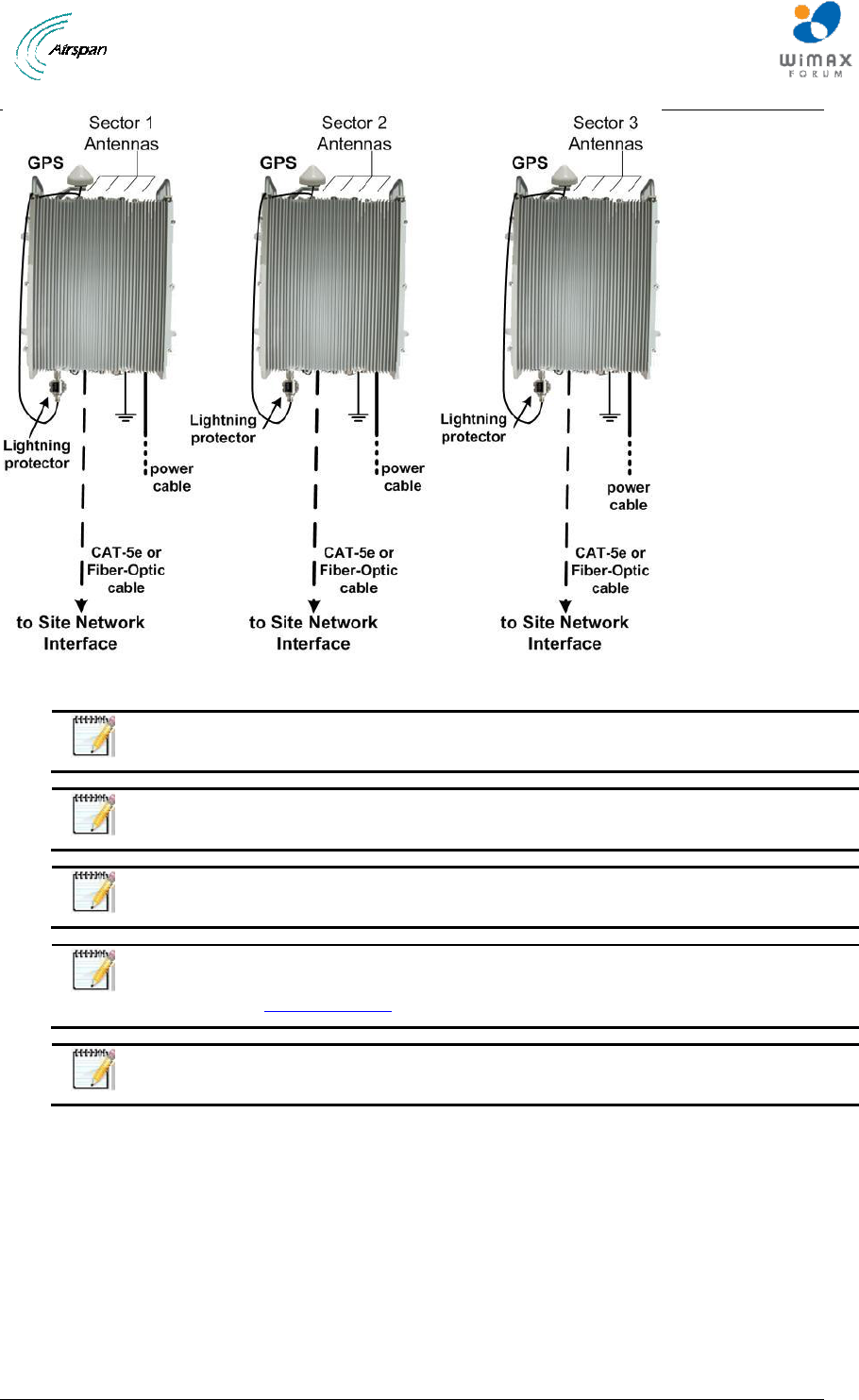
An alternative architecture, where each sector is connected separately to the backhaul/backbone
solution, therefore avoiding a single point of failure, as shown below:
Air4G-W24 Installation Guide
Page 23 Commercial in Confidence UGD-D00181 Rev G
Figure 3 - Air4G-W24 – each sector connected separately
Note: Air4G-W24 can also be connected via a LAN Switch for greater Failsafe
protection.
Note: When the Fiber-Optic cable connection is employed the Ethernet cable
connection (Eth 1) is disabled.
Note: Auto-negotiation must always be enabled on the core network side.
Note: The Ethernet connection (Eth 2) can be enabled / disabled via the Air4G-
W24 WEB interface to prevent unauthorized use. Check to enable, uncheck to
disable. See General Config.
Note: Illustration above displays the GPS connected directly to the top of the
units there is also a remote GPS antennae option.
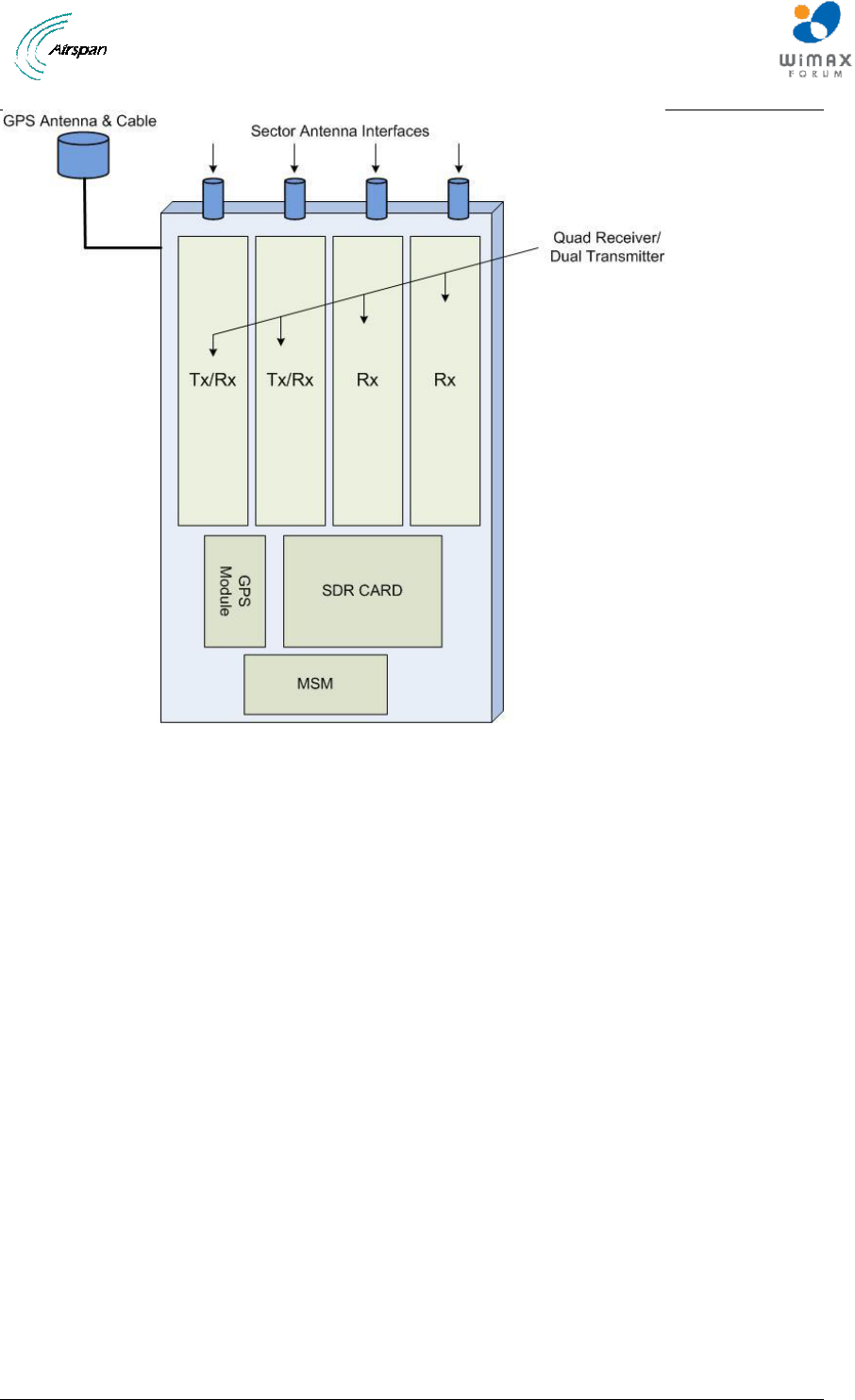
The Air4G-W24 is a fully integrated all outdoor base station sector that contains all RF, Baseband,
GPS Synchronization and 3-sector aggregation functionality. In one box it comprises the
following functional elements:
Quad Receiver / Dual Transmitter
SDR Card
Ethernet Switch
GPS
Air4G-W24 Installation Guide
Page 24 Commercial in Confidence UGD-D00181 Rev G
Figure 4 – Air4G-W24 Functional Components
Air4G-W24 Installation Guide
Page 25 Commercial in Confidence UGD-D00181 Rev G
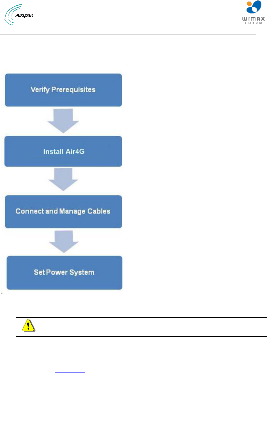
3 Getting Started
3.1 Workflow of Installation
The Workflow to install the Air4G-W24 is shown in the following diagram:
Figure 5 – Workflow of Installation
Caution: Antennas 1 & 2 Tx/Rx must be connected and attached before Air4G-
W24 is powered on.
3.2 Air4G-W24 Installation Checklist
Plan the installation of the Air4G-W24 by using the Installation Checklist, which you can find as a
removable job aid in Appendix A for this guide.
Air4G-W24 Installation Guide
Page 26 Commercial in Confidence UGD-D00181 Rev G
4 Verify Prerequisites
Prior to installing the Air4G-W24, verify the required safety, power, tools, parts and components.
Reference: Set up requirements for the installation is detailed in the Job Sheet,
see Appendix A for this guide.
4.1 Verify Safety Requirements
Read and follow all warning notices and instructions marked on the product or included in this
manual.
When installed in the final configuration, the product must comply with the applicable Safety
Standards and regulatory requirements of the country in which it is installed. If necessary, consult
with the appropriate regulatory agencies and inspection authorities to ensure compliance.
Ascertain the radiation hazards when working in an environment close to other antennas and
Electromagnetic fields, e.g. working on towers with other microwave transmitters etc. and act
accordingly.
4.1.1 Warning of Hazardous Voltages
On AC installations, hazardous voltages exist. Use caution when verifying or working with AC
power. Remove metal jewelry that could come into contact with AC power.
On DC sections, short circuiting the low voltage, low impedance circuits can cause severe arcing
that may result in burns or eye damage. Remove rings, watches etc. to avoid shorting DC circuits.
Note: Airspan products do not contain hazardous substances (as defined in UK
Control of Substances Hazardous to Health Regulations 1989 and the Dangerous
Substances Regulations 1990). At the end of any Airspan products life cycle, the
customer should consult with Airspan to ensure that the product is disposed of in
conformance with the relevant regulatory requirements.
Caution: Any modifications to this device not expressly authorized by the
manufacturer could void the user‟s authority to operate this device.
Air4G-W24 Installation Guide
Page 27 Commercial in Confidence UGD-D00181 Rev G
4.2 Verify Installation Requirements
4.2.1 Verify the Tools
Table 9 - Air4G-W24 installation tools
Tool
Large Crosshead Screw driver Phillips # 3 or Pozidrive # 3
Small flat blade screwdriver
Medium flat blade screwdriver
13mm or 1/2 inch open ended spanner
10mm or 13/32 inch open ended spanner
Wire strippers
Wire cutters
Ring terminals crimp tool
RJ45 crimp tool
4.2.2 Verify the Parts and Kits
Table 10 - Air4G-W24 installation parts and kits
Air4G-W24
Base Station
parts
Consisting of
1 x Air4G-W24
unit
Base station unit
2 x RJ45
Weatherproof
Connector
Covers
Weatherproof connector covers for use with standard cat 5 RJ45 network
connections.
Note: Previous versions had 3 RJ45 connections.
1 x mains
cable 14AWG
x2 (ordered
separately)
30 meter lead with M17 3 pole plug
When distance from outdoor Power supply to Base Station is over 30 meters additional power
cable must be connected via a junction box (ordered separately) for total distance of up to 130
meters.
14AWG x2 (ordered separately) – up to 40 meters
12AWG x6 (ordered separately) – up to 100 meters
1 x Ethernet
RJ45
environmental
shroud
LTW IP68 or Amphenol environmental connector
Air4G-W24 Installation Guide
Page 28 Commercial in Confidence UGD-D00181 Rev G
Air4G-W24
Base Station
parts
Consisting of
1 x Sunshield
fixing kit
(optional)
(ordered
separately)
including quad
antenna
adaptor
brackets (x 2).
M8 x 20 Hex Cap screws - 12
M8 plain washers - 12
M8 spring washers – 12
M8 Hex nuts - 4
M12 x 20 screws – 4
M12 nuts – 4
M12 flat washers – 4
M12 spring washers - 4
Note: The Sunshield brackets are only applicable for antennas that utilize
Mechanical Electric Tilt (MET). i.e. – Argus-SSPX310F.
Warning: A Sunshield is mandatory for temperatures of above 45°.
1 x Air4G-W24
installation
mount kit
(ordered
separately)
M8 x 20 Hex Cap screws – 8
M8 Hex nuts - 4
M8 plain washers – 8
M8 spring washers - 8
Pole Mount
Bracket
Assembly:
Dia. 120-170
mm – top &
bottom – plus
fixing
accessories.
Dia. 170-230
mm – top &
bottom – plus
fixing
accessories.
(ordered
separately)
Accessories included
Pole Mount
Bracket
Assembly:
Dia. 60-120
mm – top &
bottom – plus
fixing
accessories.
(ordered
separately)
Accessories included
Air4G-W24 Installation Guide
Page 29 Commercial in Confidence UGD-D00181 Rev G
Air4G-W24
Base Station
parts
Consisting of
1 x earth kit
1 x M5 screws
1 x M5 washers
1 x M5 spring washers
Alternative: SEMS screw (includes 2 washers)
GPS antenna
& accessories
(each ordered
separately)
1x GPS Antenna. An active GPS antenna which, by using the appropriate
mounting bracket, can be used with Air4G-W24 for network synchronization.
For mounting directly to the top of Air4G-W24, this GPS Antenna should be
used in conjunction with Air4G-W24 GPS Antenna mounting bracket w/Handle
pre-assembled on the Air4G-W24 and the 80cm GPS Cable RG58 TNC-TNC.
When mounting remotely from the base station unit, this antenna should be
used in conjunction with the Remote GPS Antenna Mounting Bracket (GPS-
MNT-1) and the 16m GPS Cable RG58 TNC-TNC.
80cm or 16m Cable Assembly - 80cm (CBL-GPS-TNC-0.8-1) or 16m (CBL-
GPS-TNC-16-1) RG58 cable. 16m connects remote mounted GPS Antenna
(GPS-ANT-1) to the Air4G-W24 via TNC connectors. The 80cm, cable for
mounting GPS directly to the top of Air4G-W24.
GPS
Lightning/Surg
e protector
(ordered
separately)
1x Lightning/Surge protector (required)
AC/DC Power
Supply (PS)
Indoor power converter for 700 MHz
Indoor power converter for 2.xGHz
Outdoor power converter for 3.xGHz
Type-IC DC
Power Cable
Available either in - 10, 15 or 30 meter lengths. Additional lengths available.
ODC Twin
Fiber Cable
(Multimode)
(optional)
(ordered
separately)
Available either in - 10, 15, 30, 50, 75 or 100 meter lengths.
Note: Maximum up to 500 meters as this is a
multimode interface.
Multimode
fiber pigtail
cable (not
included)
(optional)
(ordered
separately)
Multimode fiber pigtail cable – ODC - LC connector. Terminates the outdoor
fiber cable and provides an indoor LC connector. 2 meter length.
Grounding
Cable
(required) (not
included)
Circular earth braid, 120A current (16 mm²), jacketed or not with cable size =
AWG 4 – 6 with lug (terminal) on enclosure side with hole M6
Air4G-W24 Installation Guide
Page 30 Commercial in Confidence UGD-D00181 Rev G
Air4G-W24
Base Station
parts
Consisting of
Filter (Cavity
filter) Kit (for
2.3 GHz
variant only)
(U.S.A. – WCS
market only)
2 x Cavity Filters – 141-00-148
4 x antenna cables – 689-000-47
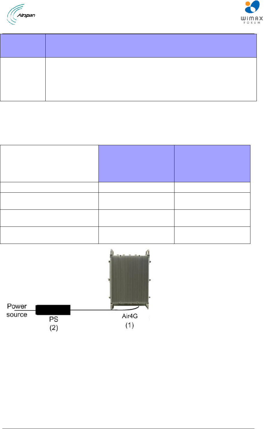
The Air4G-W24 power supply (PS) can be installed with various cable lengths according to the
site requirements. The cable lengths are determined by the length of the run between the PS and
the Air4G-W24. Use the following table to determine the required power supply output to ensure
proper operation of the Air4G-W24.
Table 11 - Input Power for Air4G-W24
Air4G-W24 2x10
(2.3-2.7 GHZ)
&
Air4G-W24 0707
(698-746 MHz)
Air4G-W24 3x05
(3.3-3.38 GHZ)
Input Voltage to Air4G-W24 (1)
-38 VDC to -60 VDC
-38 VDC to -60 VDC
PS output Voltage – 30 meter cable
(2)
-42 VDC min
-41 VDC min
PS output Voltage – 75 meter cable
(2)
-50 VDC min
-46 VDC min
PS output Voltage – 100 meter
cable (2)
-53 VDC min
-49 VDC min
Figure 6 - PS – Air4G-W24
Air4G-W24 Installation Guide
Page 31 Commercial in Confidence UGD-D00181 Rev G
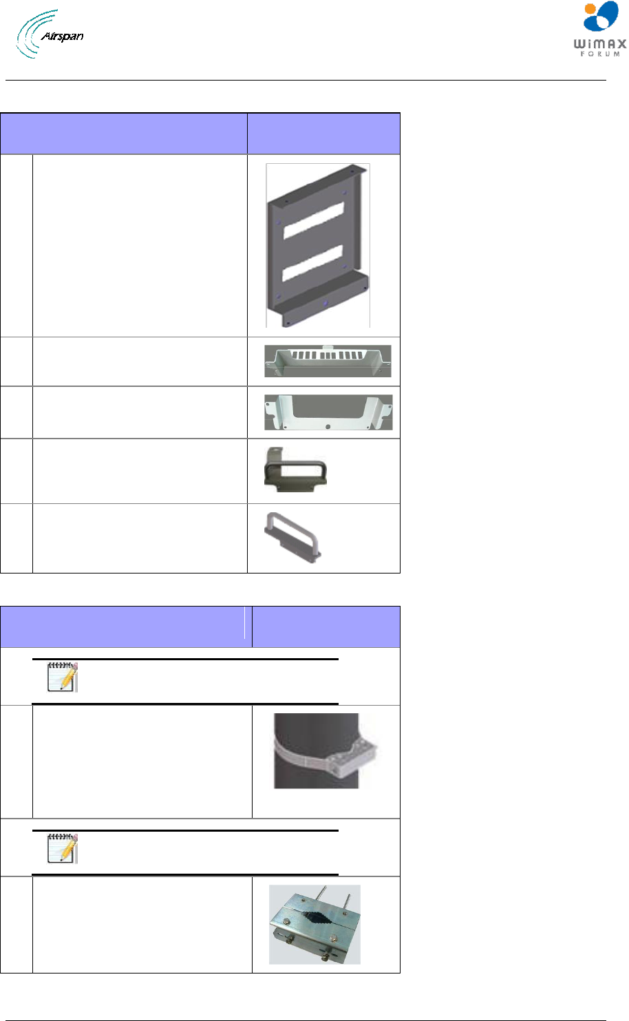
Table 12 - Air4G-W24 wall mount installation parts
Parts
Images
1
Wall Plate
2
Top Hanger
3
Lower Hanger
4
GPS Antenna mounting
bracket w/Handle (pre-
assembled)
5
Handle (pre-assembled)
Table 13 - Air4G-W24 pole mount installation parts
Parts
Images
Note: in addition to the Wall
mounting kit.
1
Top & Lower Pole Strap (x2) for
120 > 170 MM (short strap)
Top & Lower Pole Strap (x2) for
170 > 230 MM (long strap)
Top & Lower bracket (x2)
Note: in addition to the Wall
mounting kit.
2
Pole bracket for 60 > 120 MM
Table 14 - Air4G-W24 additional parts and kits
Air4G-W24 Installation Guide
Page 32 Commercial in Confidence UGD-D00181 Rev G
Additional Common Accessories
(not provided by Airspan)
Spare RJ45 connectors
Cable ties
Ring terminal for earth strap. M5 / M6
Earth strap cable (4-6 mm) (yellow and green cable)
Weatherproof / Outdoor mains cable splice kit or termination box.
Table 15 - Cavity filter (for 2.3 variant only) (U.S.A. – WCS market only)
Parts
Images
Note: the exact filter might appear
different than shown.
2
Filter (Cavity filter)
(for 2.3 variant only) + antenna
cables.
(WCS - U.S.A. market only)
4
4x pole bands (stainless steel),
as required according to on site
pole size, (not included)
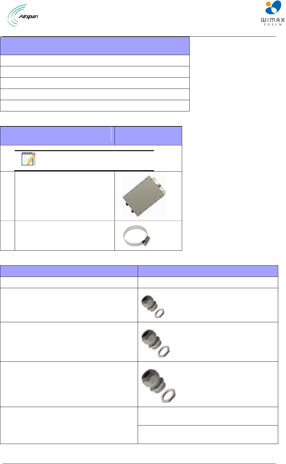
Table 16 - Junction box (optional)
Optional Junction Box
Consisting of
1 x Junction box (ordered separately)
Junction box
1 x PG11 Weatherproof gland (connector),
included with junction box
Weatherproof connector
1 x PG16 Weatherproof gland (connector) ),
included with junction box
Weatherproof connector
1 x PG29 Weatherproof gland (connector) ),
included with junction box
Weatherproof connector
Additional power cable
14AWG x2 (ordered separately) – up to 40
meters
12AWG x6 (ordered separately) – up to 100
meters
Air4G-W24 Installation Guide
Page 33 Commercial in Confidence UGD-D00181 Rev G
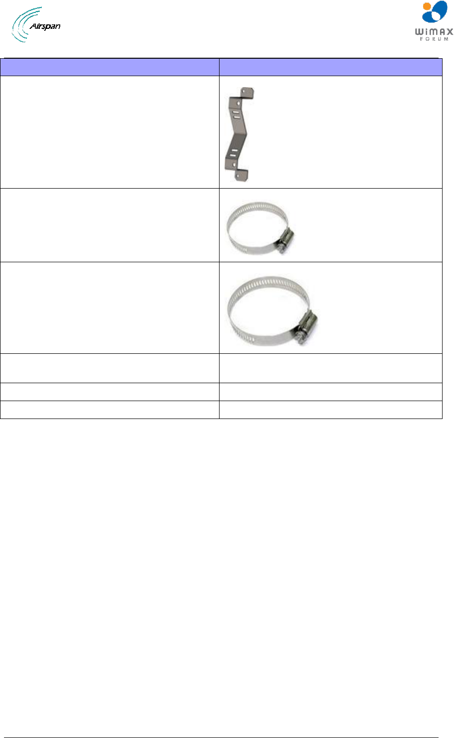
Optional Junction Box
Consisting of
2x mounting bracket(s) for pole and wall
mounting
Bracket (x2)
2x pole bands (stainless steel), as required,
supplied.
52 – 76 mm (3”)
2x pole bands (stainless steel), as required,
supplied.
78 – 102 mm (4”)
Mounting screws – for mounting brackets to
junction box.
EJOT WN1412 – K50 x 12 – 4 supplied.
Wall mounting fasteners
Hole size = 7 mm
Sufficient cable wires ties, as required
(not supplied - customer responsibility)
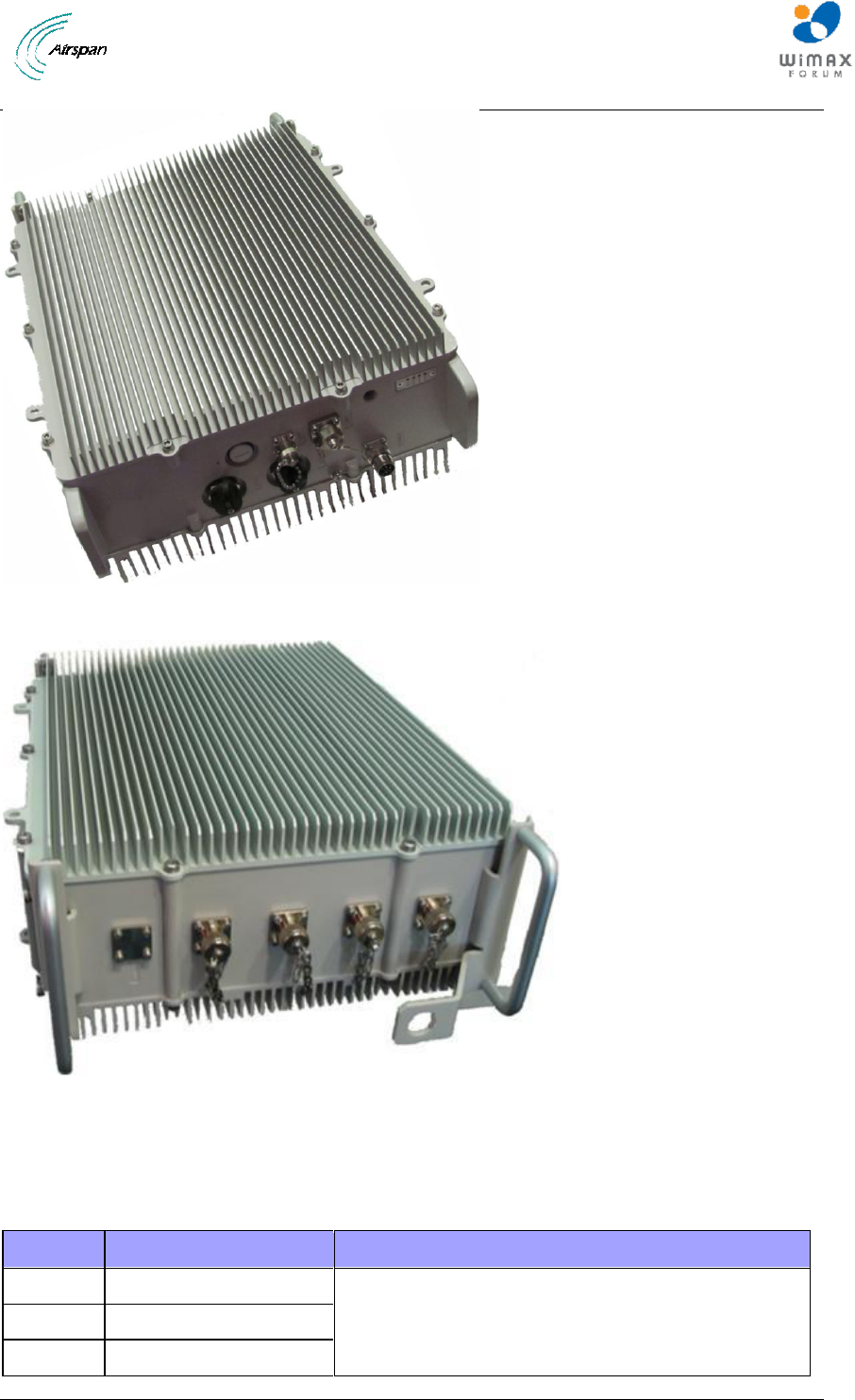
4.2.3 Verify Components
Air4G-W24 is shown below from the Ethernet termination and RF port end views respectively.
Air4G-W24 Installation Guide
Page 34 Commercial in Confidence UGD-D00181 Rev G
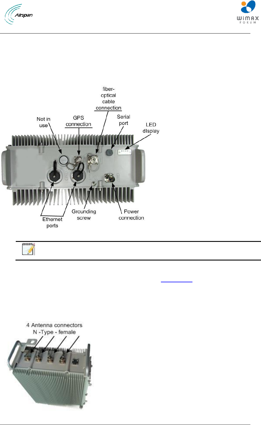
Figure 7 – Air4G-W24 Base Station Unit, Ethernet termination
Figure 8 – Air4G-W24 Base Station Unit, RF ports
4.2.3.1 Physical Dimensions
Air4G-W24 BS is in an all outdoor enclosure.
Table 17 - Air4G-W24 3.x physical dimensions
Parameter
Value
Comment
Height
410 mm (16.14 inches)
The physical dimensions exclude handles and
connectors.
Width
350 mm (13.78 inches)
Depth
155 mm (6.10 inches)
Air4G-W24 Installation Guide
Page 35 Commercial in Confidence UGD-D00181 Rev G
Parameter
Value
Comment
Weight
Aprox. 17 kg (37.47 lbs.)
Table 18 - Air4G-W24 2.x & 0707 physical dimensions
Parameter
Value
Comment
Height
410 mm (16.14 inches)
The physical dimensions exclude handles and
connectors.
Width
350 mm (13.78 inches)
Depth
170 mm (6.69 inches)
Weight
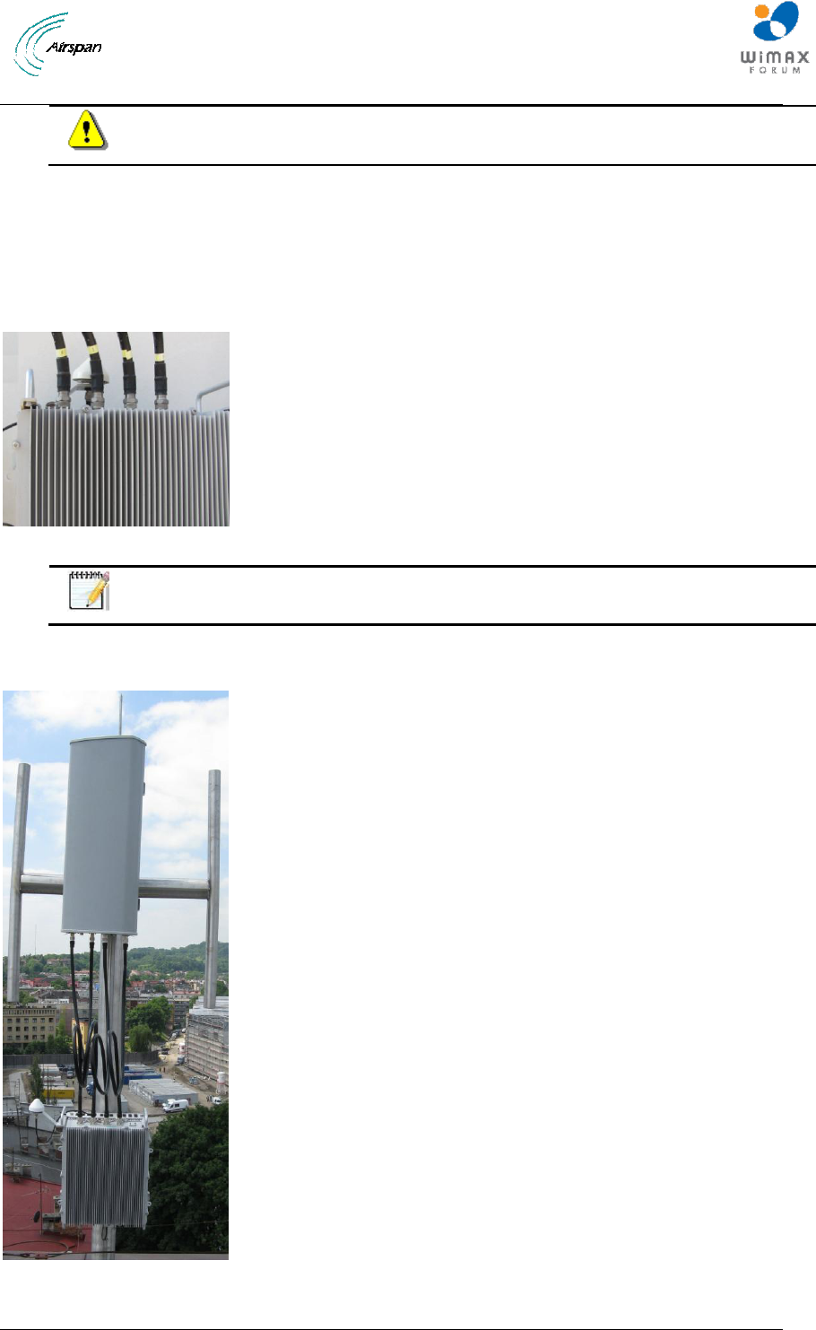
Aprox. 17.6 kg (38.80 lbs.)
RF Ports for antenna connections are N-Type Female connectors located on the top of the Air4G-
W24 enclosure. Adjacent to these are SMA connectors used for RF monitoring purposes during
installation / maintenance. For normal operation, these are covered with a weatherproof cap.
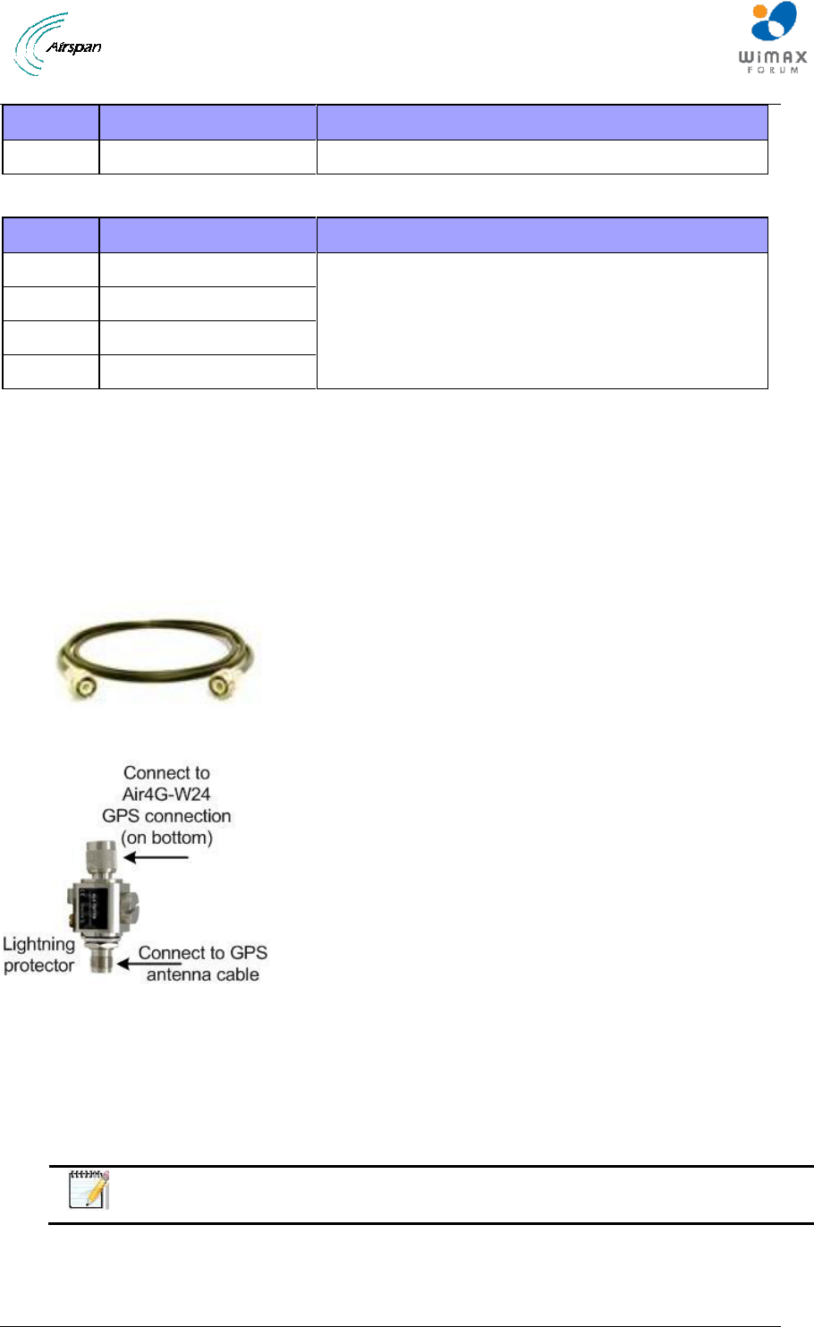
A 16m RG58 cable connects a remote mounted GPS antenna to the Air4G-W24 or 80cm cable
for connection directly on the Air4G-W24 by way of TNC connectors. Alternatively, an 80cm,
cable connects the GPS directly to the top of Air4G-W24. The cable assembly for the remote GPS
antenna is shown below.
Figure 9 – Air4G-W24 Cable Assembly for GPS Antenna
Figure 10 - Lightning/Surge protector (required)
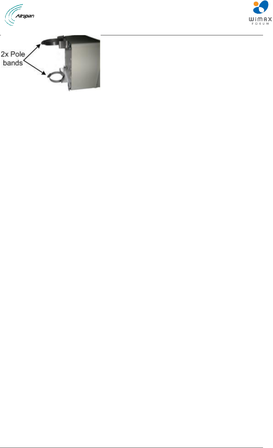
4.2.3.2 Junction Box (Optional)
The Junction box (optional) is an outdoor enclosure that measures 160 mm (6.3 in.), 160 mm (6.3
in.) and 75 mm (2.95 in.). The unit is shown below with the pole mounting bands assembled. The
Junction box is required when the distance from the outdoor Power supply to Base Station is over
30 meters for total distance of up to 130 meters.
Note: If – 48 volt DC can be verified and guaranteed the Junction box may not be
required. Contact customer support to determine.
Air4G-W24 Installation Guide
Page 36 Commercial in Confidence UGD-D00181 Rev G
Figure 11 - Junction box with pole assembly
Air4G-W24 Installation Guide
Page 37 Commercial in Confidence UGD-D00181 Rev G
5 Install Air4G-W24
Install the Air4G-W24 base station by pole mount, wall mount, or single point. The Air4G-W24
can be deployed as a remote radio head (RRH) connected to a pair of single (usually vertically
polarized) or single dual independently mounted antennas via standard RF coaxial cables.
Antennas are positioned with up to 10 wavelengths horizontal separation to give optimal Downlink
and Uplink MIMO performance.
Caution: Proper local rigging and hoisting practices should be followed when
installing the Air4G-W24. The pre-assembled handles are not to be used for
hanging, attaching or hoisting the unit into place.
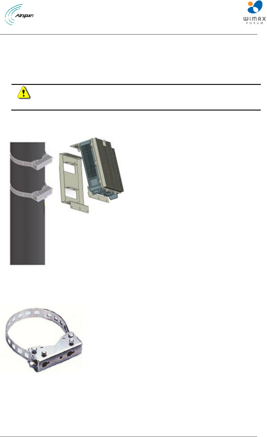
5.1 Pole mount configuration
The following image shows the pole mount assembly.
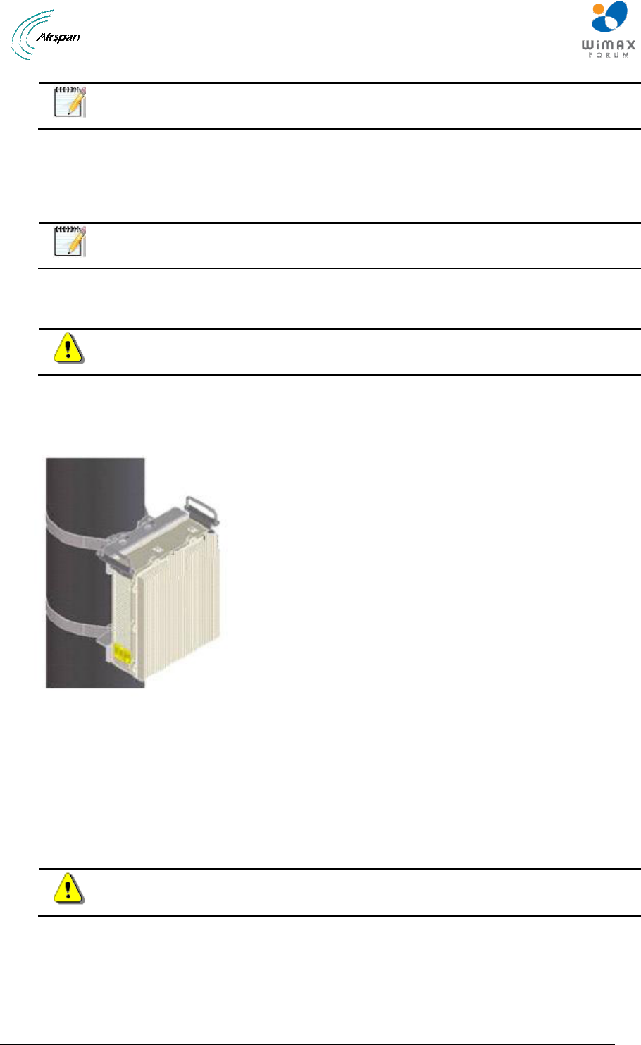
Figure 12 – Pole Mounted Air4G-W24 Assembly
To mount the Air4G-W24 in the pole mount configuration (for poles 170 > 230 mm), perform
the following steps:
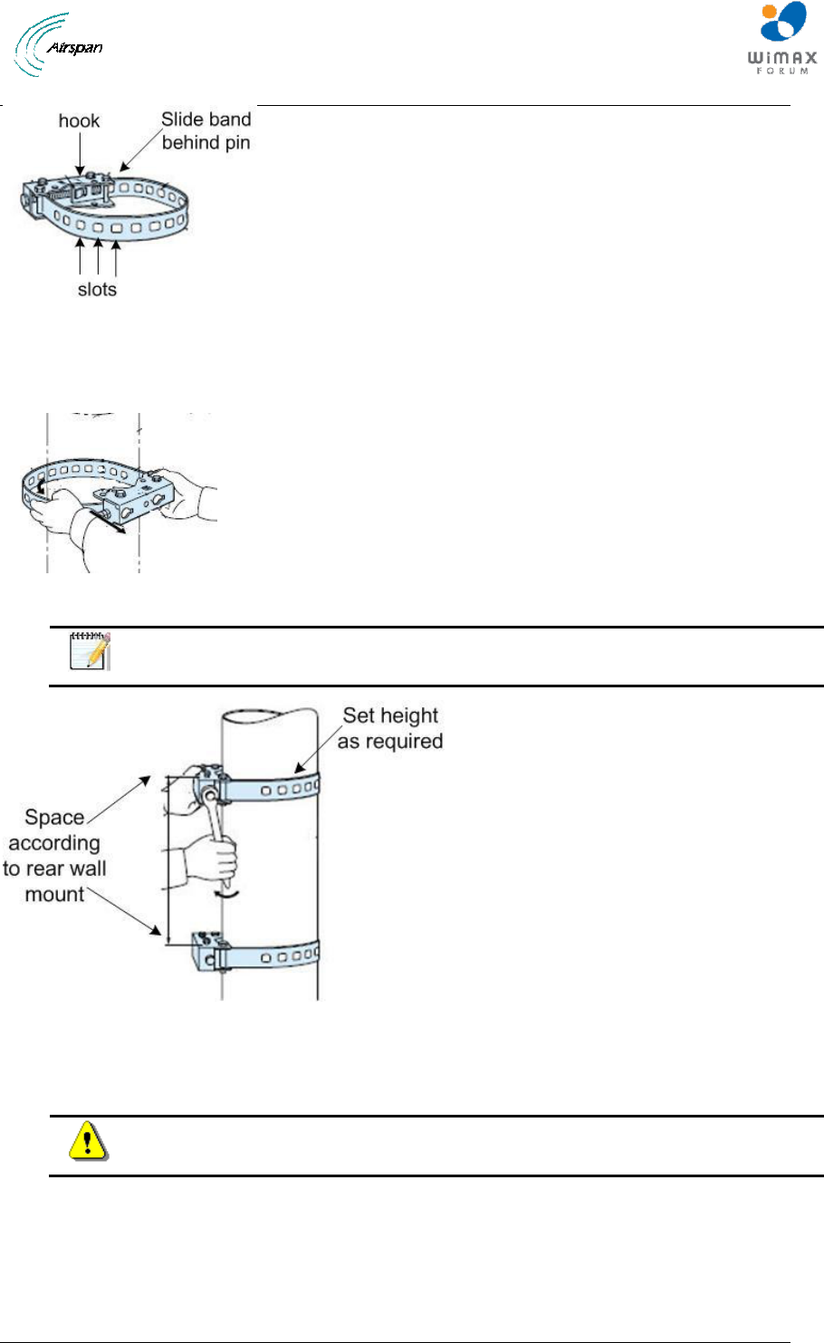
Figure 13 - pole mounting bracket (2 required)
1. Wrap the band to properly fit on the pole. Set the slot on the hook to insure a tight fit.
Air4G-W24 Installation Guide
Page 38 Commercial in Confidence UGD-D00181 Rev G
Figure 14 - pole bracket wrap
2. Align and position each of the 2 pole clamp brackets at the heights required to attach the
Air4G-W24 (with the threaded holes facing up). Adjust the upper bracket and tighten in
place. Adjust the lower bracket and hand-tighten.
Figure 15 - position brackets on pole
Note: Remove assembled screws (2) and washers (4) for later use.
Figure 16 - spacing the brackets
3. Lift the rear wall mount and place the screws through the head clearance holes and
position the unit so that the top mounting holes retain the unit.
Caution: These units weigh over 17 kg take care when lifting.
4. Screw the bottom two the M8 screws and washers into the two standoff fittings at
the bottom bracket.
5. Check and tighten all fixing screws.
To mount the Air4G-W24 in the pole mount configuration (for poles 120 > 170 mm), perform
the following steps:
Air4G-W24 Installation Guide
Page 39 Commercial in Confidence UGD-D00181 Rev G
Note: Remove long (assembled) strap and replace with short strap (supplied).
1. Wrap the band to properly fit on the pole. Set the slot on the hook to insure a tight fit.
2. Align and position each of the 2 pole clamp brackets at the heights required to attach the
Air4G-W24 (with the threaded holes facing up). Adjust the upper bracket and tighten in
place. Adjust the lower bracket and hand-tighten.
Note: Remove assembled screws (2) and washers (4) for later use.
3. Lift the rear wall mount and place the screws through the head clearance holes and
position the unit so that the top mounting holes retain the unit.
Caution: These units weigh over 17 kg., take care when lifting.
4. Screw the bottom two the M8 screws and washers into the two standoff fittings at the
bottom of the Air4G-W24 enclosure.
5. Check and tighten all fixing screws.
Figure 17 – Pole Mounted Air4G-W24
To mount the Air4G-W24 in the pole mount configuration (for poles 60 > 120 mm), perform
the following steps:
1. Attach the two (2) pole brackets (shown above in Table 6) to the pole (with the threaded
holes facing up) at the heights required to attach the Air4G-W24.
2. Tighten upper pole bracket and hand tighten (loosely) the lower pole bracket for later
adjustment.
Caution: These units weigh 17 kg – 17.6 kg, take care when lifting.
3. Lift and align the Air4G-W24 unit and place the screws through the head clearance holes
and position the unit so that the top mounting holes retain the unit and loosely tighten all
screws.
4. Tighten all fixing screws.
Air4G-W24 Installation Guide
Page 40 Commercial in Confidence UGD-D00181 Rev G
5.2 Wall mount configuration
The following image shows the wall mount assembly.
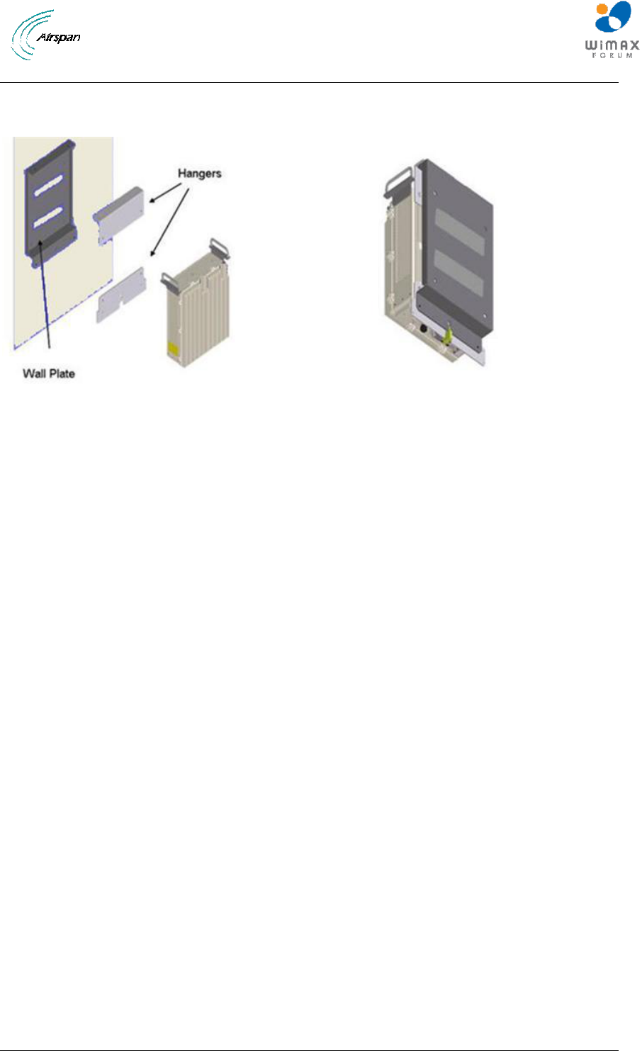
Figure 18 – Wall Mounted Air4G-W24
Air4G-W24 Installation Guide
Page 41 Commercial in Confidence UGD-D00181 Rev G
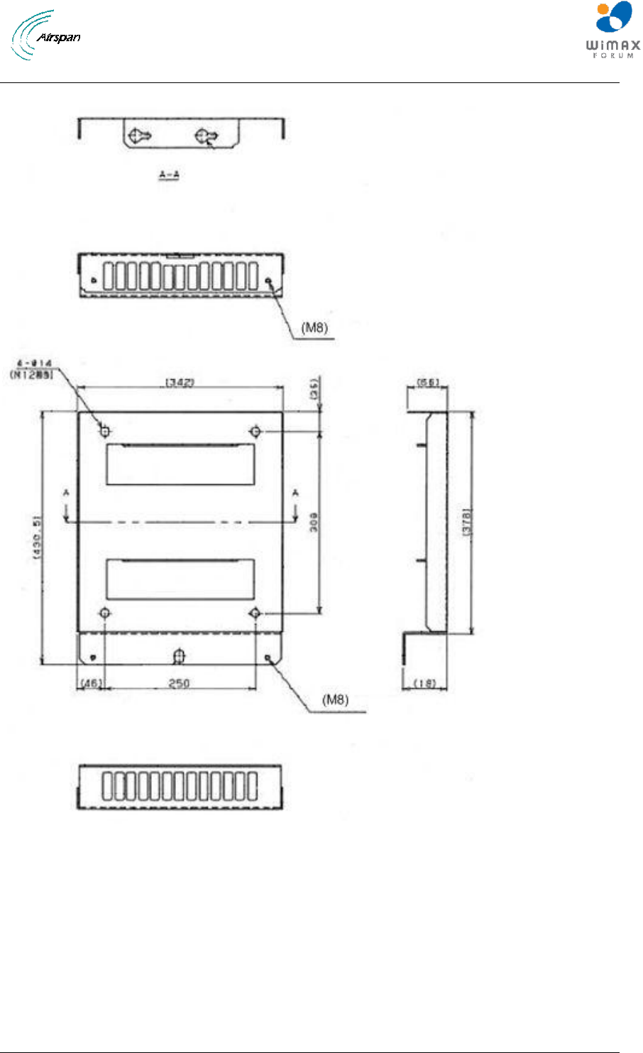
The following diagram depicts the Wall Plate Details.
Figure 19 – Wall Mounted Air4G-W24 Wall Plate Details
To mount the Air4G-W24 in the wall mount configuration, perform the following steps:
1. Attach the Wall Plate to the wall at the height required to attach the Air4G-W24.
2. Fasten the Hangars to the rear side of the Air4G-W24 enclosure, position the niched
Hangar so it is lower on the wall with the niche facing down.
3. Lift the enclosure and place the screws through the head clearance holes and position
the unit so that the top mounting holes retain the unit.
Air4G-W24 Installation Guide
Page 42 Commercial in Confidence UGD-D00181 Rev G
Caution: This unit weighs 17 kg – 17.6 kg, take care when lifting.
4. Screw the bottom two screws and washers into the two standoff fittings at the bottom of
the Air4G-W24 enclosure.
5. Tighten all fixing screws.
5.2.1 Mounting Examples
The following displays a typical wall mount.
Figure 20 - Wall mount
Note: The GPS bracket (pre-assembled) is on the (back) side closest to the wall
so as not to interfere with the sunshield assembly.
The following displays a possible assembly alternative in the event of interference to the GPS by
equipment already in place.
Figure 21 - GPS alternative assembly
Air4G-W24 Installation Guide
Page 43 Commercial in Confidence UGD-D00181 Rev G
5.3 Air4G-W24 Connections
The following diagram displays the connections on the bottom side of the Air4G-W24.
The base station requires a secure ground connection. The cable should also be grounded to the
tower which is grounded at the tower base. A grounding screw fitted with a flat washer and lock
washer is provided on the bottom of the chassis clearly marked with the universal ground symbol
as shown below.
Figure 22 - Air4G-W24 connections (bottom)
Note: Previous versions had 3 RJ45 (Ethernet) connections.
5.3.1 LED Display
The LED‟s are a visual display to indicate basic BS status, see LED Display below for a
description of the LED display.
5.4 Install Air4G-W24 Antennas
Use this procedure to install a linear dual slant antenna for the Air4G-W24 in the mast mount
configuration.
Air4G-W24 Installation Guide
Page 44 Commercial in Confidence UGD-D00181 Rev G
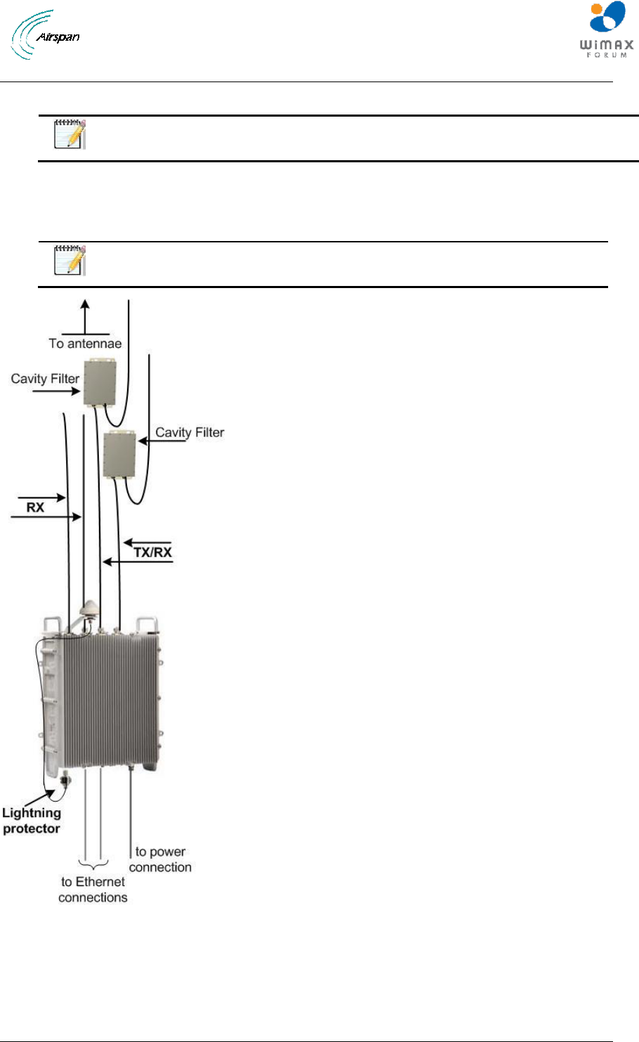
Figure 23 – Air4G-W24 External Antenna Configuration
Note: Separate antenna distance according to RF planning.
5.4.1 Cavity Filter Installation
Use this procedure to install a Cavity filter for the Air4G-W24 in either the wall or mast mount
configuration.
Note: The Cavity filters are required for the 2.3 GHz variant only.
Figure 24 - Cavity filter(s) installation
Air4G-W24 Installation Guide
Page 45 Commercial in Confidence UGD-D00181 Rev G
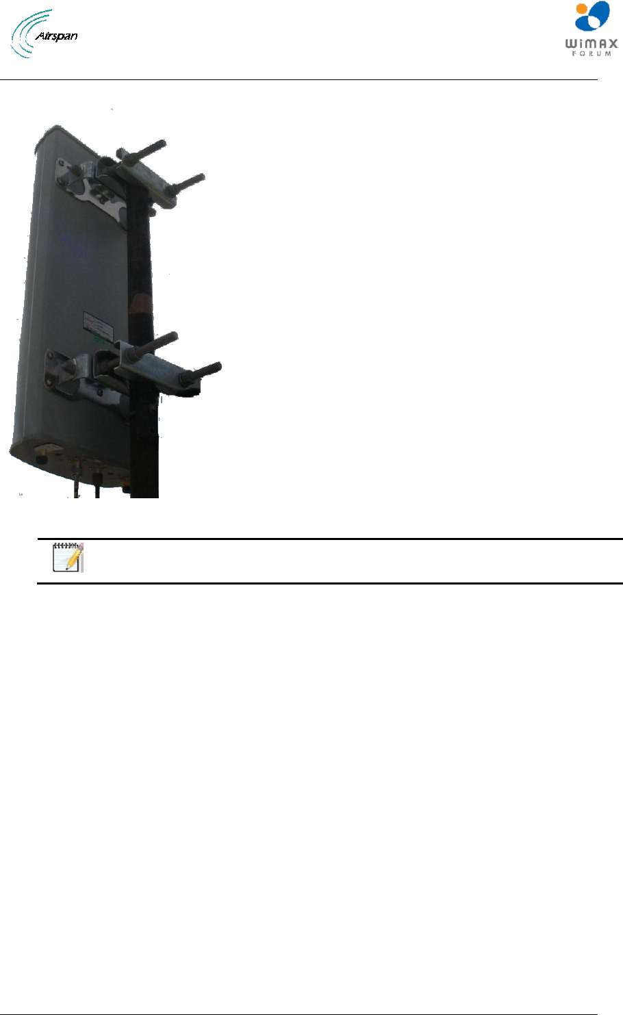
5.4.2 Install Dual Slant Antenna
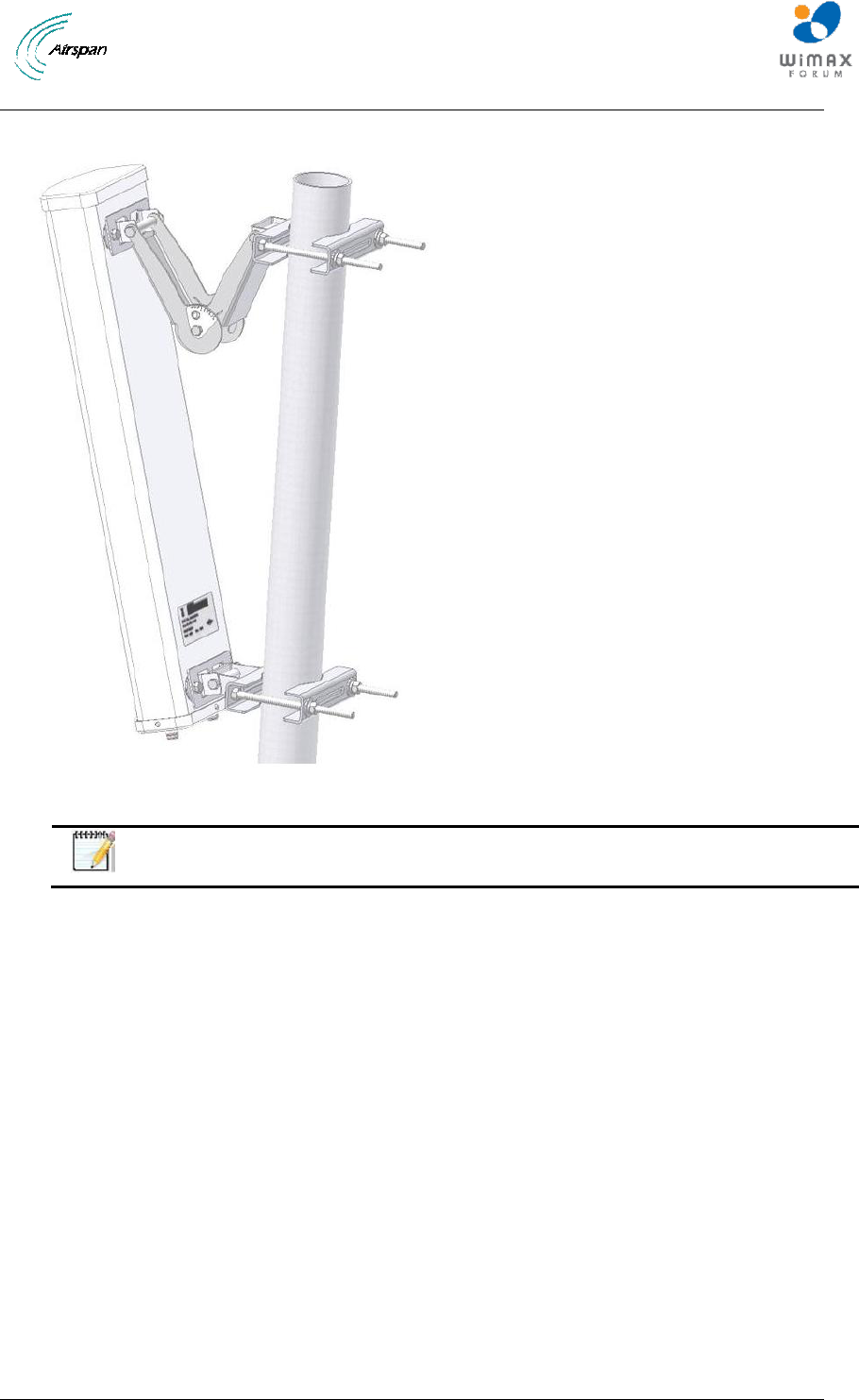
Figure 25 - Air4G-W24 Antenna Dual Slant Mast Mount Configuration
Note: Mounting kit (50 > 115 mm) is included.
To mount the dual slant antenna for the Air4G-W24 in the mast mount configuration,
perform the following steps:
1. Attach the Antenna brackets to the top and bottom of the radome.
2. Attach the tilt arm to the top bracket of the radome.
3. Fasten the ends of the adjustable pipe mounts to the top and bottom brackets of the
radome.
4. Lift the radome and place the screws through the adjustable pipe mounts and position the
radome so that the top mounting holes retain the unit.
5. Screw the bottom two screws and washers into the two standoff fittings at the bottom of
the radome assembly.
6. Tighten all fixing screws.
7. Attach, connect and secure antenna RF cable between the antenna and the appropriate
Air4G-W24 Antenna RF connection on the top of the unit.
Air4G-W24 Installation Guide
Page 46 Commercial in Confidence UGD-D00181 Rev G
5.4.3 Install Quad Slant Antenna
Figure 26 – Air4G-W24 Antenna Quad Slant Mast Mount Configuration
Note: Mounting kit (50 > 115 mm) is included.
To mount the Quad slant antenna for the Air4G-W24 in the mast mount configuration,
perform the following steps:
1. Attach the Antenna brackets to the top and bottom of the radome.
2. Attach to the top bracket of the radome.
3. Fasten the ends of the adjustable pipe mounts to the top and bottom brackets of the
radome.
4. Lift the radome and place the screws through the adjustable pipe mounts and position the
radome so that the top mounting holes retain the unit.
5. Screw the bottom two screws and washers into the two standoff fittings at the bottom of
the radome assembly.
6. Tighten all fixing screws.
7. Attach, connect and secure antenna RF cable between the antenna and the appropriate
Air4G-W24 Antenna RF connection on the top of the unit.
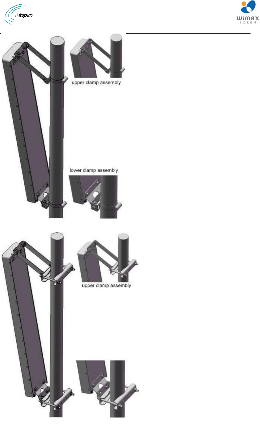
5.4.3.1 Antenna Mounting Clamps for Dual and Quad Slant Antennae
The following are some adjustable antenna mounting clamp options for both Dual and Quad Slant
antenna scenarios.
Air4G-W24 Installation Guide
Page 47 Commercial in Confidence UGD-D00181 Rev G
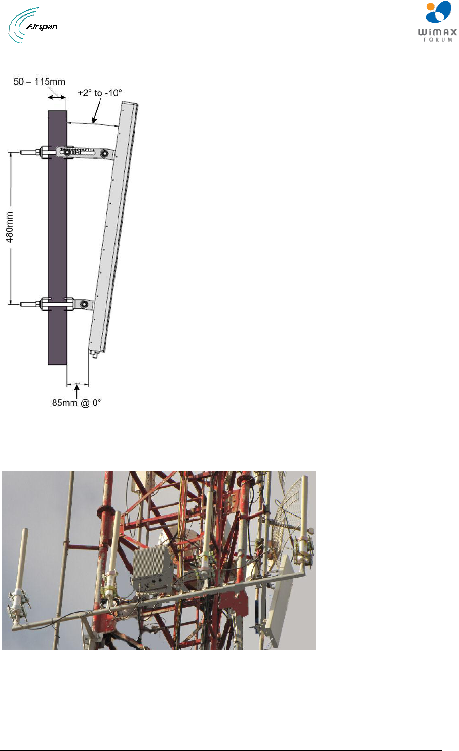
Figure 27 - Adjustable Mounting Kit, with Snaplock Stainless Steel Bands
Air4G-W24 Installation Guide
Page 48 Commercial in Confidence UGD-D00181 Rev G
Figure 28 - Adjustable Mounting Kit, with ‘V’ Blocks
Figure 29 - Adjustable Mounting Kit 2, with ‘V’ Blocks
5.4.4 Install Omni Antenna
This describes the mounting of the Omni mast mount antenna (ordered separately).
Figure 30 - possible Omni antenna array
To mount the Omni antenna for the Air4G-W24 in a mast mount configuration, perform the
following steps:
1. Assemble Omni antenna array on the ground at the installation site.
2. Attach the antennas to the mast and connect the cables while on the ground.
Air4G-W24 Installation Guide
Page 49 Commercial in Confidence UGD-D00181 Rev G
3. Use the mounting brackets provided with the antenna(s).
4. Carefully connect the antenna and mast assembly to its mounting bracket and tighten the
clamp bolts.
Note: This assembly requires more than one (1) person to assemble in place.
The recommended distance between Omni antennas is determined by the frequency band,
as shown in the table below:
Frequency
Distance between antennas
3.x
0.85 meters
2.x
1.20 meters
0707
4 meters
5.5 Optional Mounting Antenna on Air4G-W24
Either Antenna shown can be mounted on the Air4G-W24 unit or mast mounted.
Note: The sunshield kit is required for this type of assembly. Contact your
supplier to order.
5.5.1 Variable Tilt Antenna
There is a Variable Tilt Antenna available for mounting on the Air4G-W24. The antenna maybe
connected directly to the Air4G-W24 with no need for physical tilting of the antenna.The Manual
Electric Tilt (MET) antenna has a rotating nut that adjusts a threaded rod which moves in and out
while displaying a tilt scale, as shown below.
Figure 31 - Variable tilt antenna
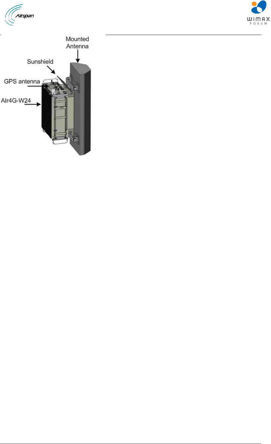
Air4G-W24 Installation Guide
Page 50 Commercial in Confidence UGD-D00181 Rev G
Figure 32 - Antenna mounted on Air4G-W24
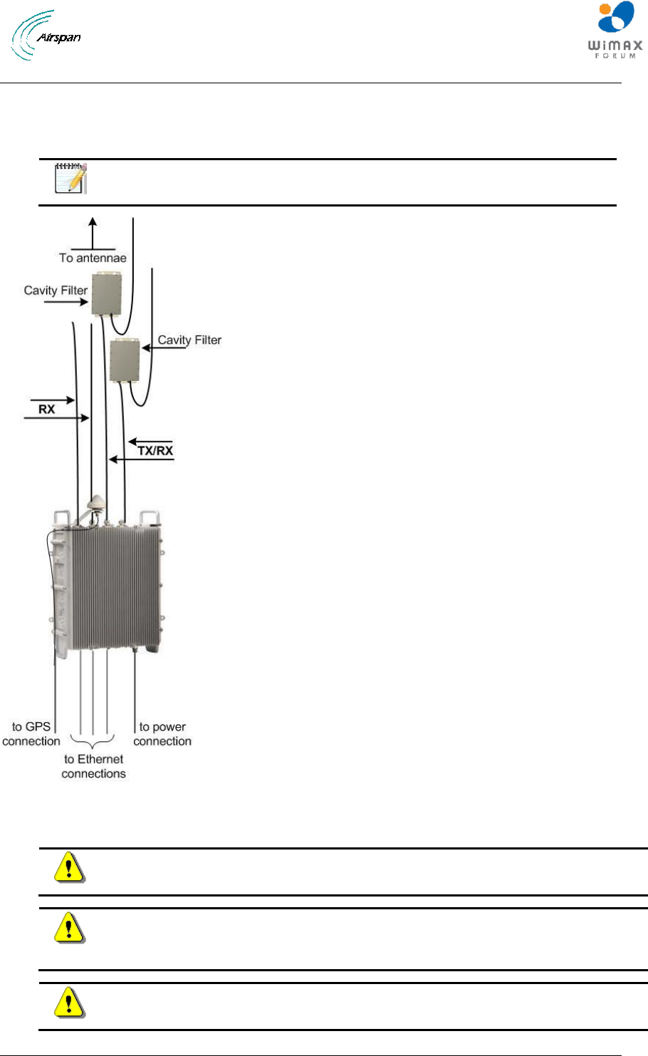
Air4G-W24 Installation Guide
Page 51 Commercial in Confidence UGD-D00181 Rev G
5.6 Cavity Filter Installation
The following demonstrates the correct installation of a Cavity filter for the Air4G-W24 in either the
wall or mast mount configuration.
Note: The Cavity filters are required for the 2.3 GHz variant only.
Figure 33 - Cavity filter(s) installation
5.7 Antenna Connection
Caution: Antennas 1 & 2 Tx/Rx must be connected and attached before Air4G-
W24 is powered on.
Caution: Attach the appropriate cable to the antenna and hand-tighten. Torque
the N-Type connector to 6.2 - 9.7 in-lbs or 0.7 - 1.1 N-m using either a 19mm or
13/16” open end Torque wrench (depending on coupling type).
Caution: Power down Air4G-W24 prior to disconnecting antenna.
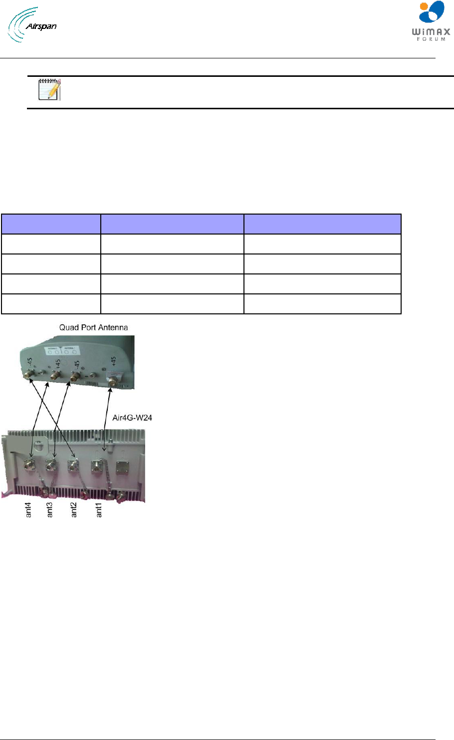
Air4G-W24 Installation Guide
Page 52 Commercial in Confidence UGD-D00181 Rev G
The following describes the antenna connection:
Note: Some antennas are labeled 1, 2, 3, 4 and some are labeled „+‟, „–„, „+‟, „–„.
The quad port antenna has two dual slant antennas in it (meaning two +/-45 degree antennas) –
as such it has two “+45 degree” ports and two “-45 degree” ports.
To provide maximum efficiency one Air4G-W24 Tx/Rx port must be connected to a “+45 degree”
port in the quad port antenna and another Air4G-W24 Tx/Rx port must be connected to a “-45
degree” port in the quad port antenna. The Air4G-W24 Rx ports need to be connected to the
remaining connectors on the antenna side. Two (2) examples are displayed below.
Table 19 - Antenna connection
Air4G-W24 port
Port Label on Air4G-W24
Port on the quad port antenna
Tx/Rx
ANT 1
+45 degree of “first antenna”
Tx/Rx
ANT 2
-45 degree of “second antenna”
Rx
ANT 3
-45 degree of “first antenna”
Rx
ANT 4
+45 degree of “second antenna”
Figure 34 - Quad port antenna connection – 1
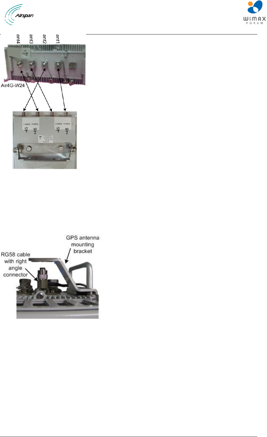
Air4G-W24 Installation Guide
Page 53 Commercial in Confidence UGD-D00181 Rev G
Figure 35 - Quad port antenna connection – 2
5.8 GPS Antenna Assembly
To mount the GPS antenna directly on the Air4G-W24:
1. Route the RG58 cable through the flat washer and the 2 nuts (supplied).
2. Position the RG58 cable below the mounting hole on the GPS antenna mounting bracket,
as shown below:
Figure 36 - GPS cable assembly prior to mounting
3. Hand-tighten the RG58 cable TNC (90°) connector to the mating connector on the GPS
antenna.
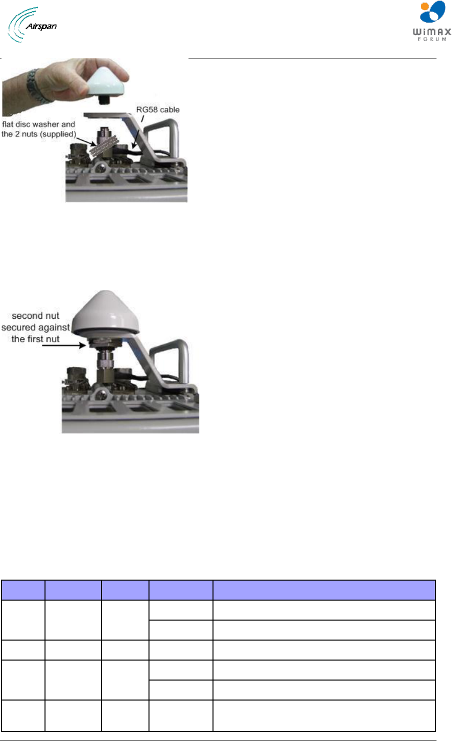
Air4G-W24 Installation Guide
Page 54 Commercial in Confidence UGD-D00181 Rev G
Figure 37 - Attach GPS antenna to RG58 cable
4. Slide the flat washer up to the underside of the mounting bracket, then thread 1 nut onto
the GPS antenna threaded base and tightened.
5. The second nut is then secured and tightened against the first nut to create a clamp load
against the first nut, as shown below:
Figure 38 - GPS antenna assembled on bracket
6. Connect the RG58 cable attached to the GPS Lightning/Surge protector (required) to the
GPS connection on the bottom Air4G-W24.
7. Verify that the weatherproof cable is in the proper position and hand tighten the cable
(using no tools), to prevent water leakage. Apply self amalgamating insulating tape on all
critical connections.
5.9 LED Display
When powering up refer to the following for indication of BS current status:
Table 20 - LED Display
LED
Name
Color
Status
Description
PWR
Power
Green
On
Power on
Off
Power off
ALM
Alarm
Red
On
Alarm detected
NML
Network
Link
Green
Steady on
Network link detected
Blinking
Traffic currently flowing
STA
In
service
Green
On
Software running
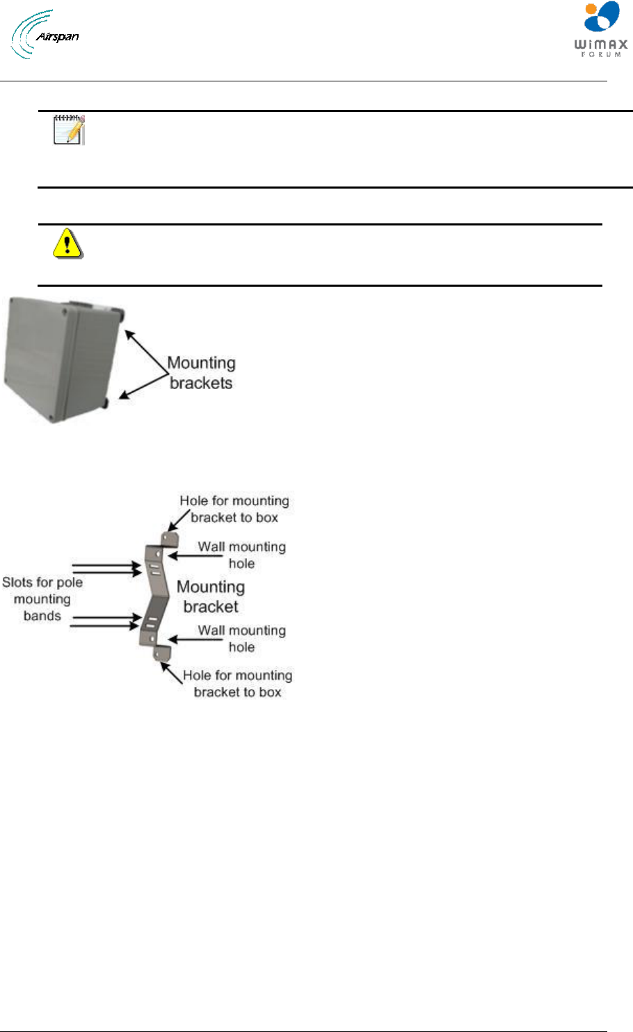
Air4G-W24 Installation Guide
Page 55 Commercial in Confidence UGD-D00181 Rev G
5.10 Install Junction Box (Optional)
Note: Contact Airspan customer-service to determine whether junction box
installation is required. Installation may be required, depending on the distance
between the external power-supply and the BS, as well as the minimum voltage
supplied by the power-supply.
The Junction box (optional) can be pole-mounted or wall-mounted.
Warning: Mount the junction box in an orientation such that the cable ports
(located on the bottom) face downwards. This prevents rain water from
settling on the ports, thereby, avoiding damage.
Figure 39 - Junction box with mounting brackets assembled
For either mounting method, the mounting bracket provides mounting holes (displayed below):
Figure 40 - mounting bracket (2 required)
5.10.1 Junction Box Installation
To install the junction box:
1. Prior to installation connect the 2 mounting brackets to the back of the junction box
fastening to the provided holes. The wall mounting hole orientation should be towards the
outer edges of the junction box.
2. Remove the junction box‟s cover, leaving the rubber gasket in place.
3. Prepare the cables for connection by performing the following:
a. Strip about 25.4 mm (1 inch) of the outer jacket of the cable to expose the wires.
b. Using a wire-stripping tool, expose about 6.3 mm (0.25 inch) of each of the wires by
stripping the wires‟ insulation.
4. Determine which cable entry holes are to be used and remove the appropriate plug.
Table 21 - Cable hole sizes
Air4G-W24 Installation Guide
Page 56 Commercial in Confidence UGD-D00181 Rev G
Cable Entry hole determination
Gland hole PG11 (M18) for cable terminating at MicroMAXe
Gland hole PG29 (M36) for cable 12AWG x6
Gland hole PG16 (M22) for cable 14AWG x2
Note: Save the rubber grommets from the plugs to be used on the weatherproof
glands (connectors).
5. Remove the nut on the weatherproof connector and slide the rubber grommet onto the
threaded shaft.
6. Set the weatherproof connector into the hole and from inside the box, thread the included
nut onto the shaft until tight.
7. Insert the exposed wires into the relevant screw-type terminal block (+ to + and – to –)
and then secure them in place by tightening the screw of each terminal.
8. Fasten the Junction box onto the pole or wall as required within the required distance of
the Air4G-W24 enclosure.
9. Perform the same procedure (steps 3-7) with the cable terminating in the in the Air4G-
W24 enclosure.
10. Open the connector clamp collar and feed about 101.6 mm (4 inches) of cable from the
Air4G-W24 through it and into the box. Tighten the collar around the cable, forcing the
seal to compress around the cable.
11. Replace the cover by using the four (4) screws, ensuring the gasket (for weatherproofing)
is firmly in place on the rim of the cover.
Note: It is important to provide strain relief and drip loop for the cables. Create a
drip loop and strain relief using cable tie, to tie cable to pole, as displayed in the
figure below:
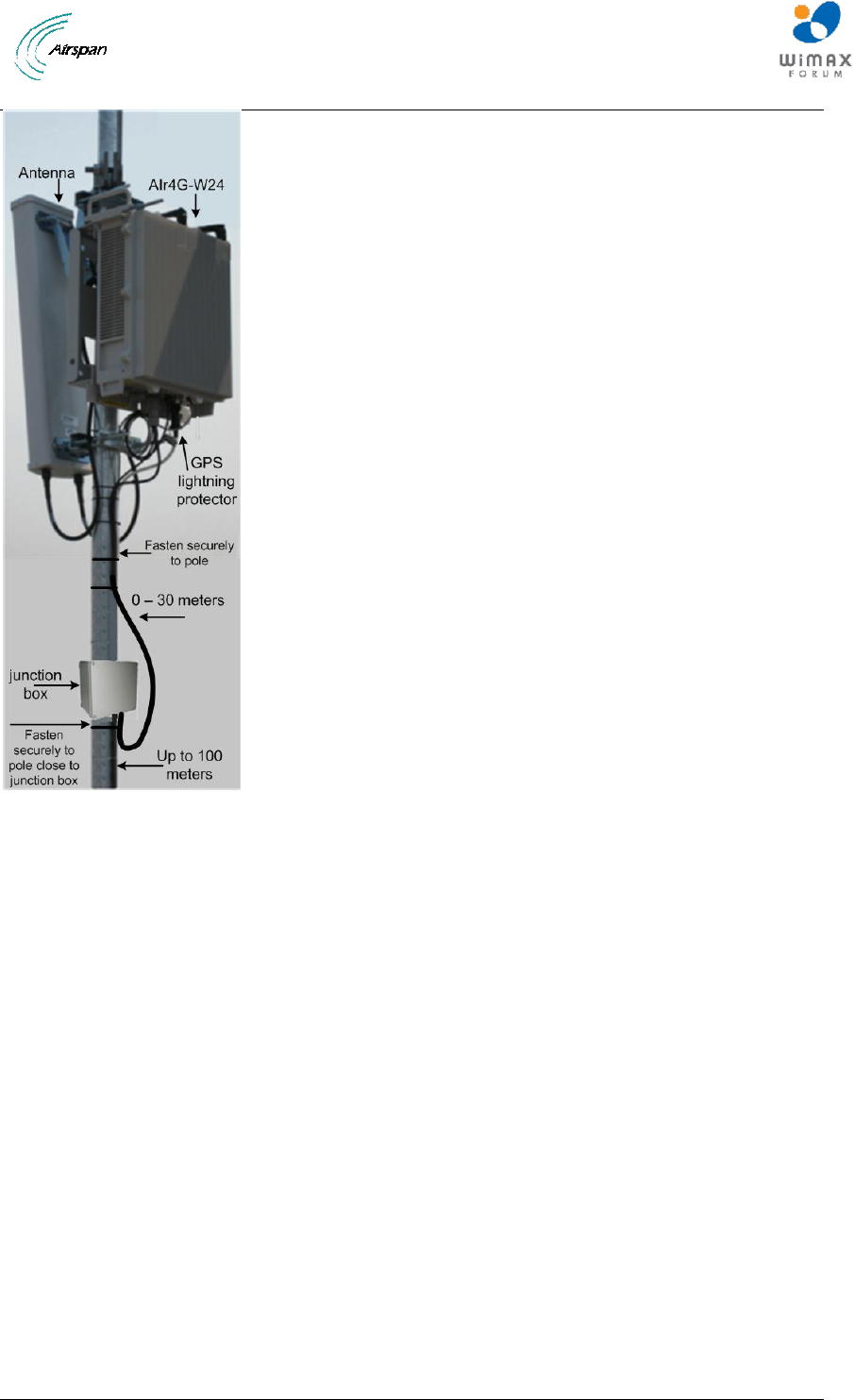
Air4G-W24 Installation Guide
Page 57 Commercial in Confidence UGD-D00181 Rev G
Figure 41 - Air4G-W24 assembly with optional junction box
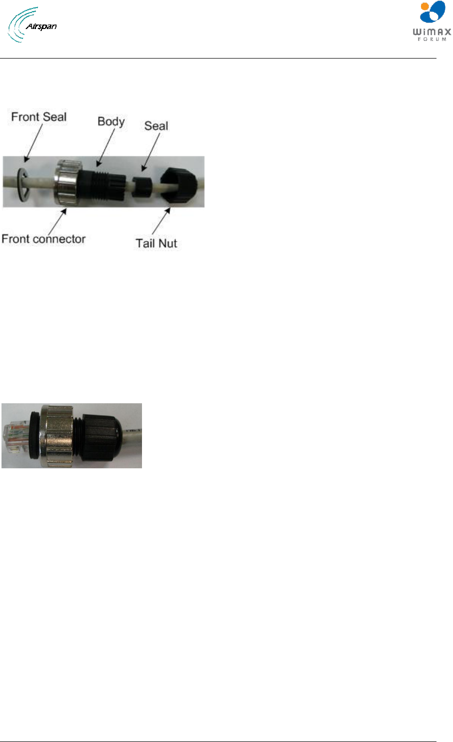
Air4G-W24 Installation Guide
Page 58 Commercial in Confidence UGD-D00181 Rev G
6 Connect and Manage Cables
The Ethernet cable is connected to the Air4G-W24 using a standard RJ45 connector protected by
a harsh environment protective casing.
Figure 42 – Ethernet connector cable termination
6.1 Assemble Ethernet Connector
1. Pass the Cat 5 cable through the seal, front connector, body and tail nut of the
environmental connector casing as shown above.
2. Paste the front seal on the collar of the connector body.
3. Terminate the Ethernet cable with an RJ45 connector plug.
4. Seat the RJ45 connector plug securely into the body cavity.
5. Tighten the tail nut on to the body forcing the seal to compress around the cable.
Figure 43 – Ethernet environmental connector assembly
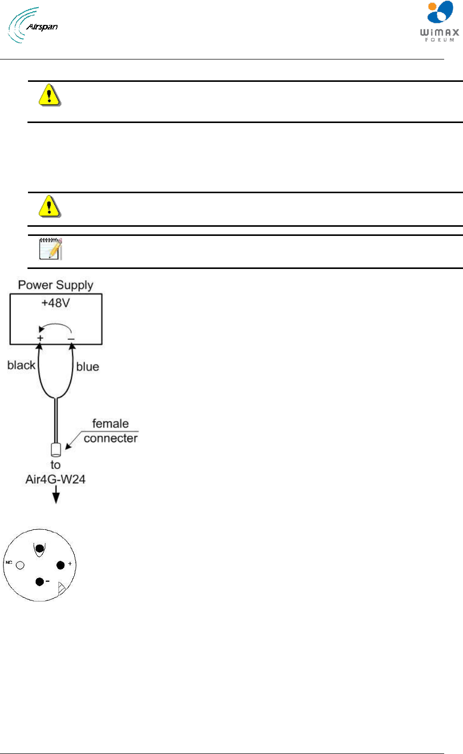
Air4G-W24 Installation Guide
Page 59 Commercial in Confidence UGD-D00181 Rev G
7 Set Power System
Hazardous voltage! Before working, ensure that the power is removed from the
power connection cables. When the system is powered on, do not touch the
power terminals.
7.1 Power Input - DC
Each unit is provided with a 3/10/30 meter 48 volt power cable terminated with a female
connector at one end to be connected to the Power connector on the bottom panel of the Air4G-
W24 and bare wires at the other.
Caution: It is important that the power connector is attached at the correct end or
damage to the connector/equipment will result.
Note: Check Power Supply for proper polarization.
Figure 44 – DC Power connection
Figure 45 - Power connector – Air4G-W24 bottom panel
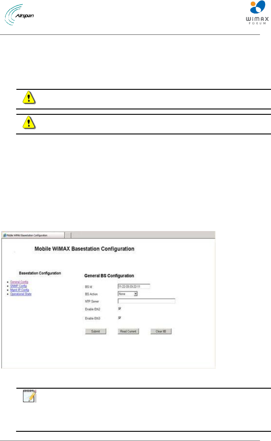
Air4G-W24 Installation Guide
Page 60 Commercial in Confidence UGD-D00181 Rev G
8 Initial WEB Configuration
Configure an Air4G-W24 base station using the built in web based interface. This prepares the
equipment for connection to Netspan.
8.1 Initial configuration
To set initial configuration, perform the following:
Caution: The GPS antenna should be installed and attached before Air4G-W24
is powered on.
Caution: Wait two minutes before performing other actions.
1. Apply power to the Air4G-W24.
2. With the Air4G-W24 powered-up connect the PC to the Ethernet port.
3. Configure the PC with an IP address in the 192.168.0.xxx range (e.g. 192.168.0.xxx
subnet 255.255.255.0).
4. In a browser, open web page with address 192.168.0.1 (Air4G-W24 default IP address).
5. Enter the default username and password:
Username = macromaxe
Password = macromaxe
8.1.1 General Config
Figure 46 – General BS Configuration Initial
Notes:
There are 4 connections on the Air4G-W24 – optical, Eth1, Eth2 and Eth3.
The Optical/Eth1 connection is always enabled, and cannot be disabled via
the GUI, to prevent comm-loss. When both are connected, the optical takes
precedence over the Eth1.
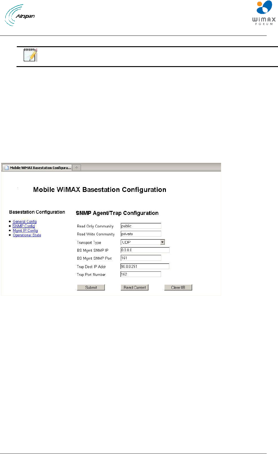
Air4G-W24 Installation Guide
Page 61 Commercial in Confidence UGD-D00181 Rev G
6. Enter the BS ID
Note: The format of the BS ID is important: NN-NN-NN-nn-nn-nn (where NN-
NN-NN is the Operator ID and nn-nn-nn is a unique address ID).
7. Select the BS Action from the available list.
8. Leave NTP Server as is (blank).
9. Check Enable Eth2 – to enable the Eth2 port – disable to prevent unauthorized access to
port. Default = enabled
10. Check Enable Eth3 – to enable the Eth3 port – disable to prevent unauthorized access to
port. Default = enabled
11. Click Submit. (Read Current = ignore/no action) (Clear IIB = ignore/no action)
8.1.2 SNMP Agent/Trap Configuration
1. Click SNMP Config, as displayed below:
Figure 47 - SNMP Initial Configuration
2. Define Read Only Community - SNMP read only community name defined by the BS
network provider
3. Define Read Write Community - SNMP read/write community name defined by the BS
network provider.
4. Leave Transport Type as is.
5. Leave BS Mgmt SNMP IP as is.
6. Leave the BS Mgmt SNMP Port number as is. Default = 161
7. Define the SNMP Trap Dest IP Addr. (IP address of Netspan)
8. Set the SNMP Trap Port Number (for communications with Netspan) to 162.
9. Click Submit. (Read Current = ignore/no action) (Clear IIB = ignore/no action)
8.1.3 Mgmt IP Config
1. Click Mgmt IP Config, as displayed below:
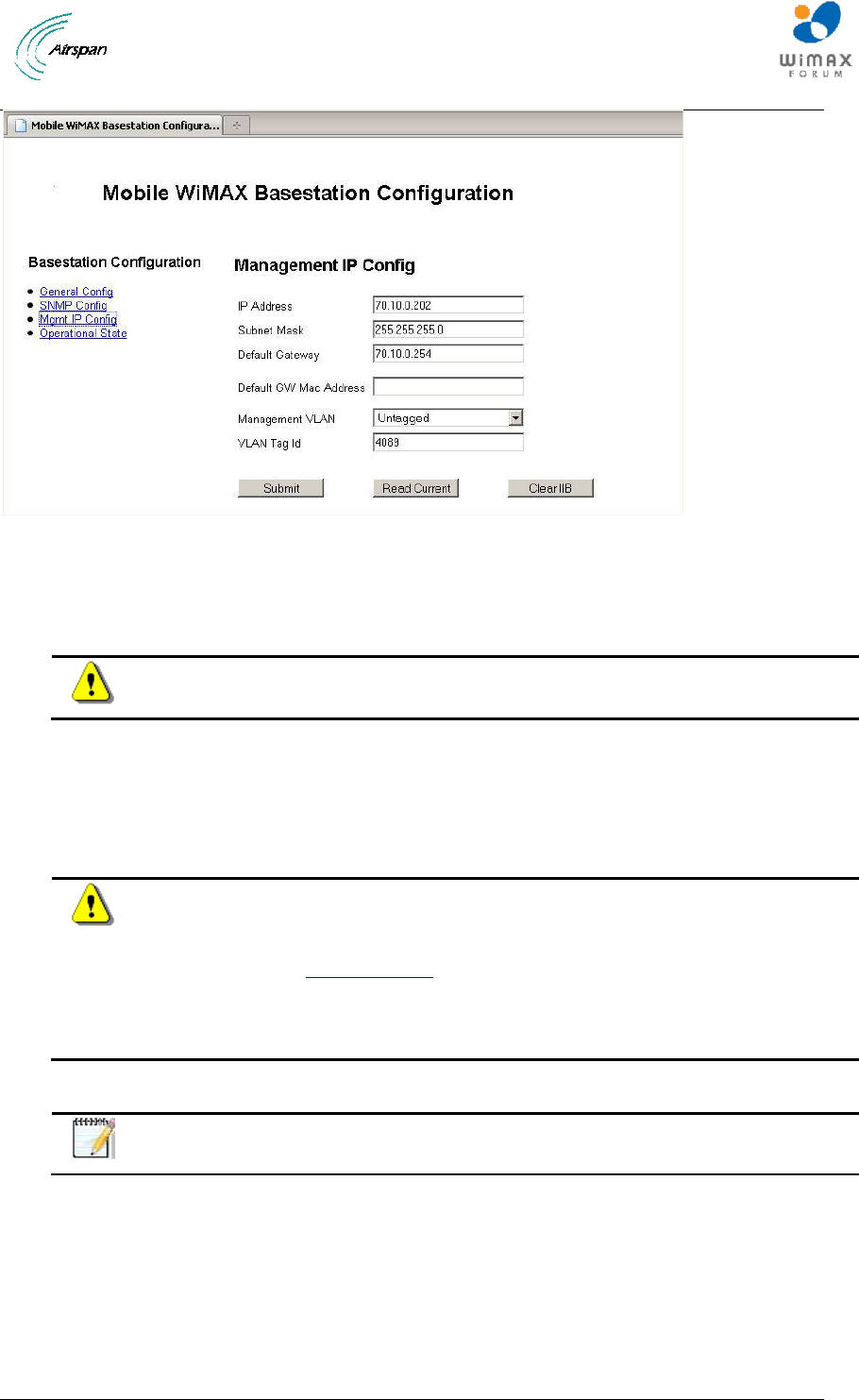
Air4G-W24 Installation Guide
Page 62 Commercial in Confidence UGD-D00181 Rev G
Figure 48 - Management IP Configuration
2. Define the IP address.
3. Define the Subnet Mask.
4. Define the Default GW MAC Address.
Caution: Define Default GW only if required for Network Security. Consult with
Provider.
5. Set the Management VLAN set to Untagged. Set to Tagged when with VLAN Tag ID.
Consult with Provider.
6. Define the VLAN Tag ID – only when Management VLAN is set to Tagged. Consult with
Provider.
7. Click Submit. (Read Current = ignore/no action)
Caution: After Submit changes are applied immediately to the BS. Therefore the
PC must now be re-configured to the new configuration (IP address and Subnet
mask) to re-establish communication.
1. Return to General Config and in the BS Action.
2. Select Reset BS from the dropdown list.
3. Click Submit to perform a reset of the BS.
8.1.4 BS Operational State
Note: Leave settings on BS Operational State as is. No configuration is required.
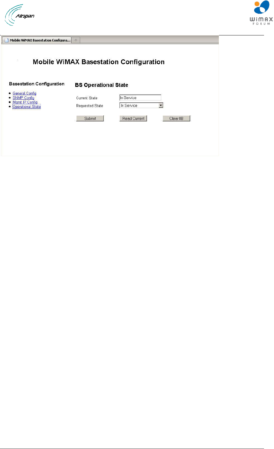
Air4G-W24 Installation Guide
Page 63 Commercial in Confidence UGD-D00181 Rev G
Figure 49 - Operational State

Air4G-W24 Installation Guide
Page 64 Commercial in Confidence UGD-D00181 Rev G
9 Appendix A
9.1 Review Job Sheet
The Job Sheet should include the following information:
BS location and identity.
Whether the system is required to be locked to a GPS timing reference.
A BSID is required for each BS TRx. This should be in a format xxxxxx:xxxxxx
where x is a decimal digit.
Network configuration information for the BS TRx.
Traffic Port: Not applicable.
IP Address: Should only be set if Management IP Mode is set to Static IP Address. See
below for Management IP Mode parameter.
Netmask: Should only be set if Management IP Mode is set to Static IP Address. See
below for Management IP Mode parameter.
Default Gateway: Should only be set if Management IP Mode is set to Static IP Address.
See below for Management IP Mode parameter.
Management VLAN: Specified as either Untagged or Tagged
Management VLAN Tag: Should only be set if Management VLAN is set to Tagged
Management IP Mode: Specified as Static IP Address or Obtain IP Address via DHCP
Ethernet Mode: Specified as Auto-negotiate or Fixed
Ethernet Rate: Need only be configured if Ethernet Mode is set to Fixed, specified as
10M or 100M.
Ethernet Duplex: Need only be configured if Ethernet Mode is set to Fixed, specified as
Full or Half.
SNMP configuration information. This will allow events from the BS to arrive at the
specified Netspan server. This will include the following information:
Read Only Community: This should be specified to the same value as in Netspan
Discovery Parameters (found under Server on Netspan left hand panel).
Read Write Community: This should be specified to the same value as in Netspan
Discovery Parameters (found under "Server" on Netspan left hand panel).
SNMP Port Number: This should be specified to the same value as in Netspan
Discovery Parameters (found under "Server" on Netspan left hand panel).
IP Address: This specifies Netspan IP address (found under Server Global
Configuration, which is under Server on Netspan left hand panel).
Community: Normally specified to the same value as for Read Only Community.
Port Number: Normally specified to a value of 9023.
NTP configuration. This specifies a list of NTP servers.
9.2 Securing Fiber-optic Cable
The Milli-Tie can be used to secure cables in the same manner as normally used for nylon straps.
The steps below show the basic use of the product.
Caution: Over-tightening of cable ties may causes damage and degrade system
performance.
To secure fiber-optic cables, perform the following steps:
1. Place the Millie-Tie around the target, and thread the tongue through the last large
aperture in the rearmost cell.
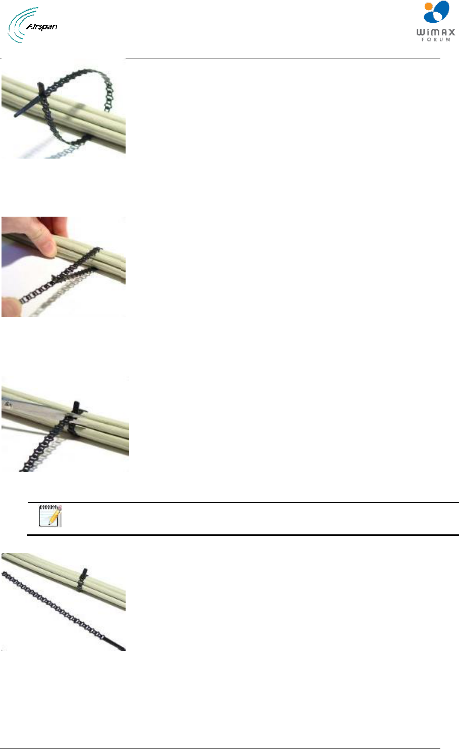
Air4G-W24 Installation Guide
Page 65 Commercial in Confidence UGD-D00181 Rev G
Figure 50 - Secure fiber-optic cable, place tie
2. Pull or slide the Millie-Tie onto the target. Note that the Millie Tie stretches to cushion the
installation.
Figure 51 – Secure fiber-optic cable, pull tie
3. Release the tension when snug, then cut and remove any excess strip. Always cut
through the square sections, not the wider cells.
Figure 52 – Secure fiber-optic cable, snug tie
Note: Millie-Tie is efficient, and simply gets a little shorter after each use. The
remaining strip can be kept and reused.
Figure 53 – Secure fiber-optic cable, cut excess tie
6. Repeat these steps for each use.
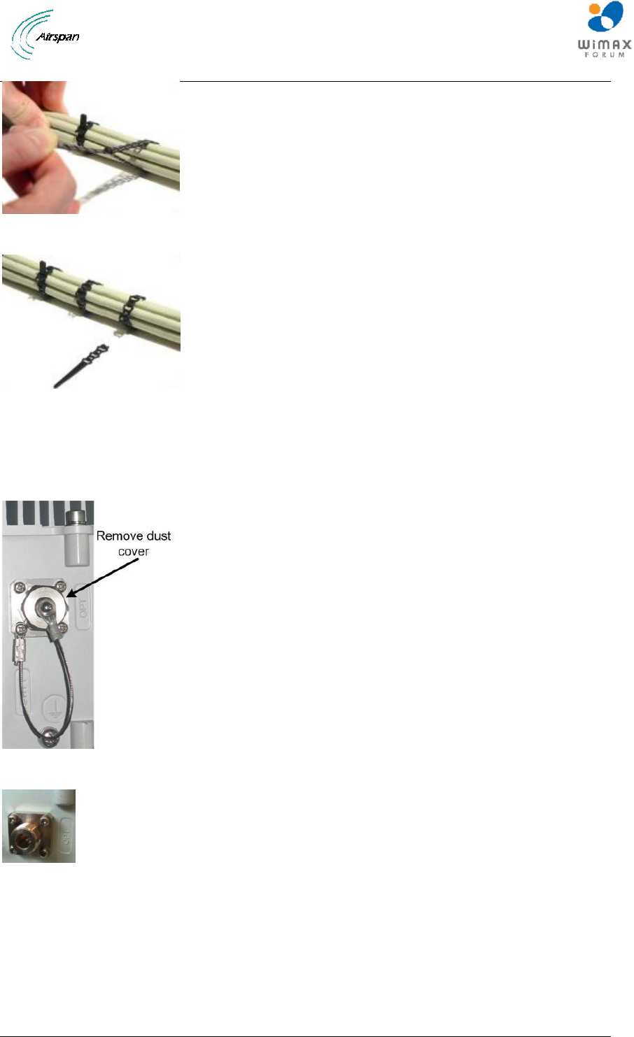
Air4G-W24 Installation Guide
Page 66 Commercial in Confidence UGD-D00181 Rev G
Figure 54 – Secure fiber-optic cable, use excess tie
Figure 55 – Secure fiber-optic cable, re-use excess tie
9.3 Connecting the Fiber-optic Cable
To secure fiber-optic cable to the Air4G-W24, perform the following steps:
1. Remove the dust cover from end of a panel connector:
Figure 56 - fiber-optic connector with dust cover
Figure 57 – dust cover removed
7. Remove the protective cover from the fiber-optical cable.
8. Align the fiber-optical cable connector and line up the groove on the cable connector with
the pin on the panel connector.
9. Screw the connecter cover nut until hand-tight.
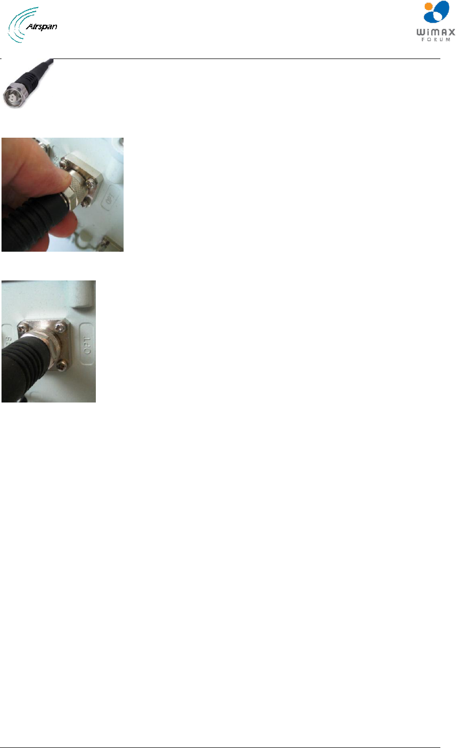
Air4G-W24 Installation Guide
Page 67 Commercial in Confidence UGD-D00181 Rev G
Figure 58 - Fiber-Optic Outdoor Connector Plug (multimode)
Figure 59 - screw hand-tight
Figure 60 - Fiber-optic cable connected

Air4G-W24 Installation Guide
Page 68 Commercial in Confidence UGD-D00181 Rev G
10 Appendix C – Glossary of Terms
AAA
Authentication, Authorization and Accounting
AAS
Advanced Antenna System
AF
Application Function
ARQ
Automatic Repeat reQuest
ASN
Access Service Network
ASN GW
ASN Gateway
ATCA
Advanced Telecommunications Computing Architecture
BS
Base Station
BWA
Broadband Wireless Access
CHAP
Challenge Handshake Authentication Protocol
CPE
Customer Premises Equipment
CQI
Channel Quality Indicator
CSN
Connectivity Service Network
DSM
Digital Surface Model
DTM
Digital Terrain Model
EAP
Extensible Authentication Protocol
FA
Foreign Agent
FBSS
Fast Base Station Switching
GUI
Graphical User Interface
HA
Home Agent
H-ARQ
Hybrid Automatic Repeat reQuest
HO
Handover/Handoff
IMS
IP Multimedia Subsystem
IP
Internet Protocol
IPsec
IP security
LR
Location Register
MAC
Media Access Control
MDH
Macro Diversity Handover
MIMO
Multiple Input Multiple Output
MIP
Mobile IP
MRC
Maximal Ratio Combining
MS
Mobile Station
NAP
Network Access Provider
NAS
Network Access Server
NLOS
Non Line of Sight
NSP
Network Service Provider
NWG
Network Working Group

Air4G-W24 Installation Guide
Page 69 Commercial in Confidence UGD-D00181 Rev G
OBSAI
Open Base Station Standard Initiative
OFDMA
Orthogonal Frequency Division Multiplexing (Multiple Access)
PA
Paging Agent
PAAA
Proxy AAA
PC
Paging Controller
PF
Policy Function
PHY
PHYsical Layer
PMIP
Proxy MIP
PPP
Point-to-Point Protocol
RADIUS
Remote Authentication Dial In User Service
RRA
Radio Resource Agent
RRC
Radio Resource Controller
RRM
Radio Resource Management
SAS
Smart Antenna System
SDR
Software Defined Radio
SFA
Service Flow Authorization
SFM
Service Flow Management
SIM
Subscriber Identity Module
SIP
Session Initiation Protocol
SOFDMA
Scalable Orthogonal Frequency Division Multiplexing (Multiple
Access)
STC
Space Time Coding
TDD
Time Division Duplex
VoIP
Voice over IP
X.509
ITU-T standard for PKI digital certificates
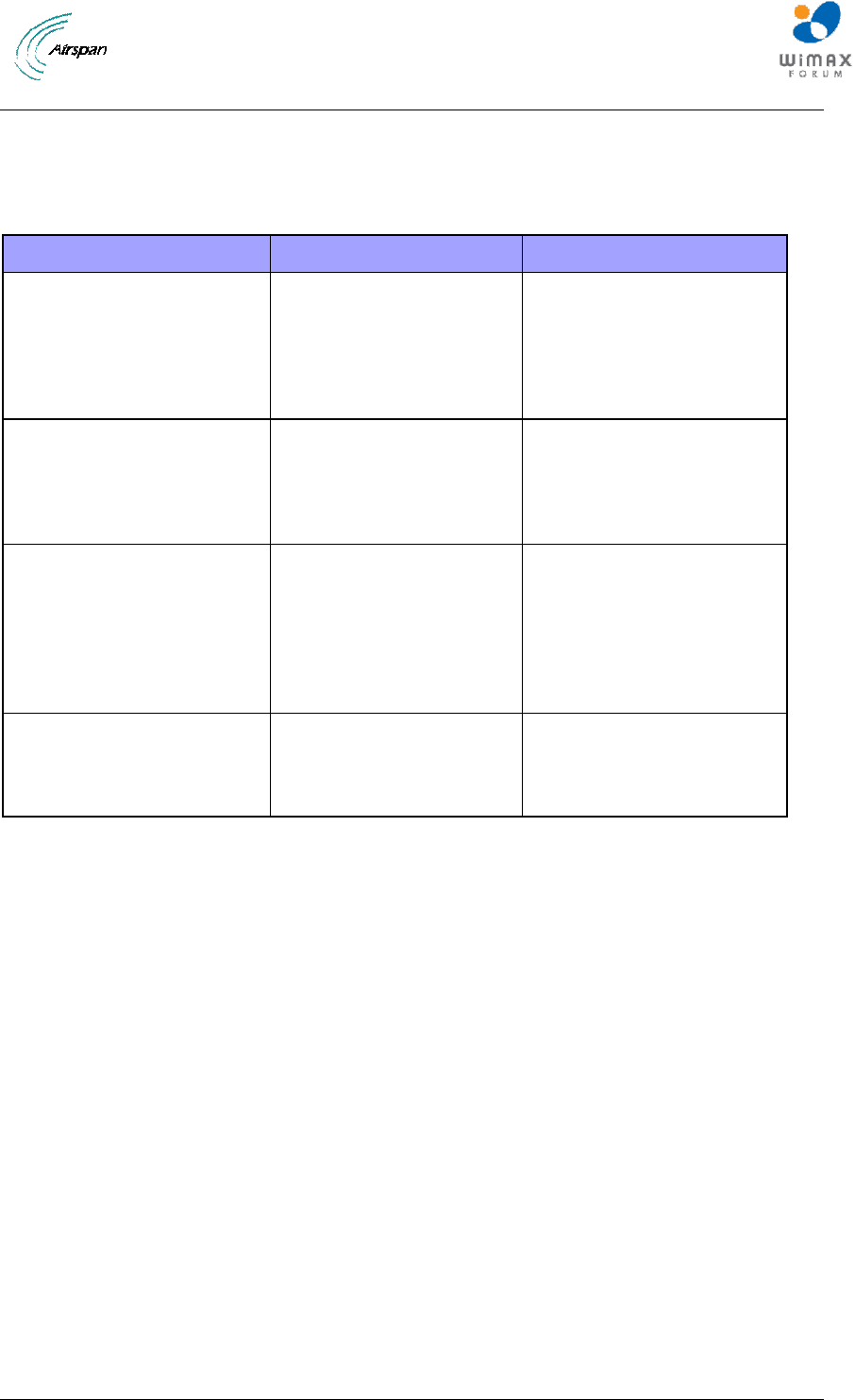
Air4G-W24 Installation Guide
Page 70 Commercial in Confidence UGD-D00181 Rev G
11 Appendix D – Installation Checklist
The Checklist below gives the high-level steps in the Workflow for this procedure. Detach or print
this page to use as a job-aid for completing the actions this procedure requires.
Table 22 - Checklist for Procedure
Procedure
Actions
Outcome
1. Verify Prerequisites
Verify safety
requirements
Verify installation
requirements
All requirements are in
place for a successful
commissioning of Air4G-
W24.
2. Install Air4G-W24
Pole mount configuration
Wall mount configuration
Install Air4G-W24
antennas
3. Connect and manage
cables
Assemble Ethernet
connector or
Disassemble Ethernet
connector, then
Assemble LTW Ethernet
connector
4. Set power system
Power input
Power output
Air4G-W24 Installation Guide
Page 71 Commercial in Confidence UGD-D00181 Rev G
12 Appendix E
12.1 Revision History
Revision
Originator
Date
Description
Draft 1
D. Cann
2-2009
Initial document
Draft B
M. Falik
3-2009
Additional content &
template changes
Rev A
M. Falik
10-2009
Additional content
Rev B
M. Falik
10-2009
Corrected Graphics +
Additional content
Rev C
M. Falik
12-2009
Added Junction box
data
Rev D
M. Falik
12-2009
Additional content
Rev E
M. Falik
03-2010
Frequency ranges and
latest support
Rev E1
M. Falik
05-2010
Added antenna
connection
Rev E2 + 3
M. Falik
06-2010
Antenna connection
table correction
Rev F, F1, F3 & F4
M. Falik
08-2010
Added 2x10⁻⁴, 0707
variants - PS cable
lengths – MAX output
Rev G – G9
M. Falik
05-2011
Product name change
+ additional content
12.2 31BContact Information
Customer Service Help-Desk for customer service emergency
Airspan Networks have introduced the Airspan Tracker application to enable prompt and efficient
Customer Support services.
If you do not have an Airspan Tracker account, please obtain login credentials by filling-in the
form in the main page www.airspan.com/Support Register New Account
Worldwide Headquarters:
Airspan Networks Inc.
777, Yamato Road, Suite 310,
Boca Raton, FL 33431, USA
Tel: +1 561 893 8670
93Hwww.airspan.com
Feedback:
To provide feedback on this document, please send comments to the following email
address: 94Hdocumentfeedback@airspan.com