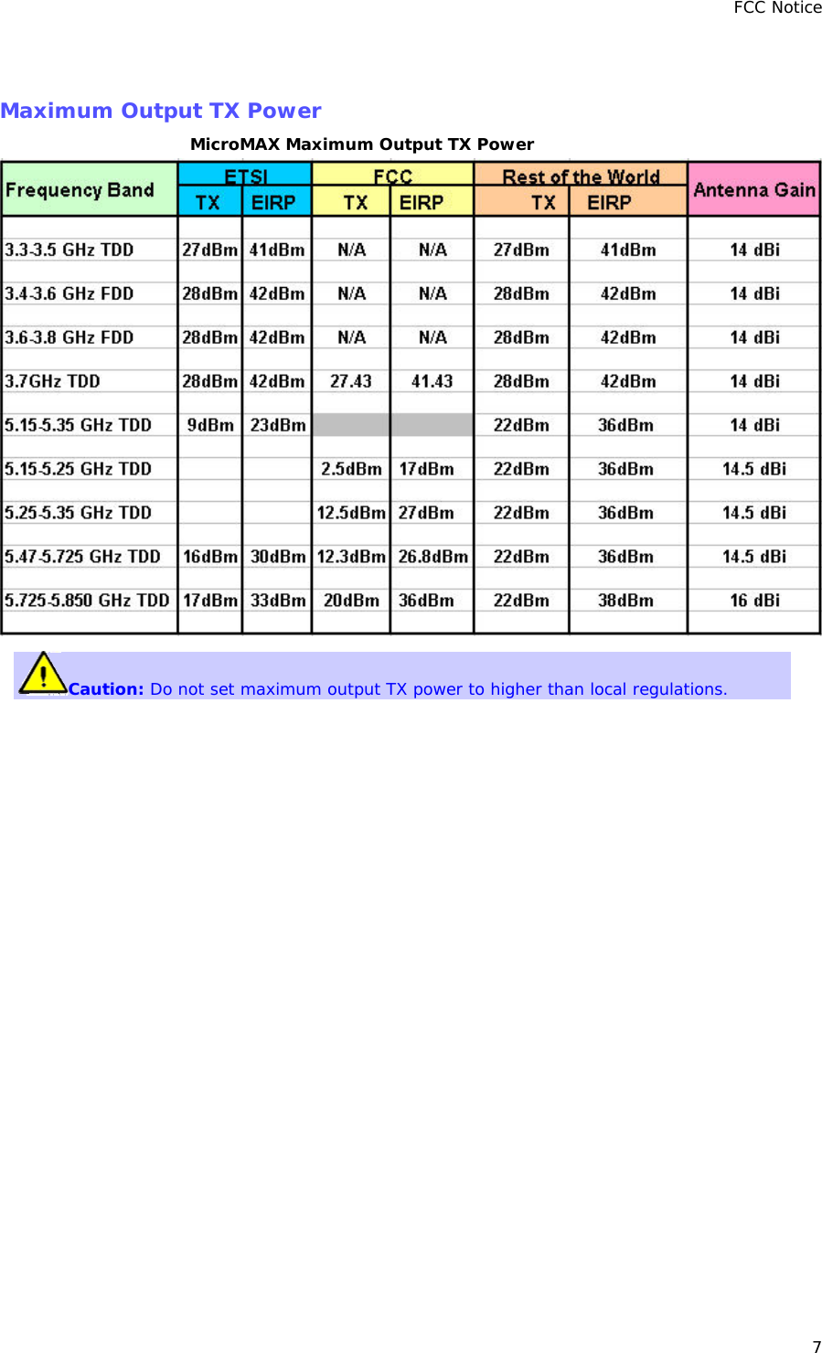
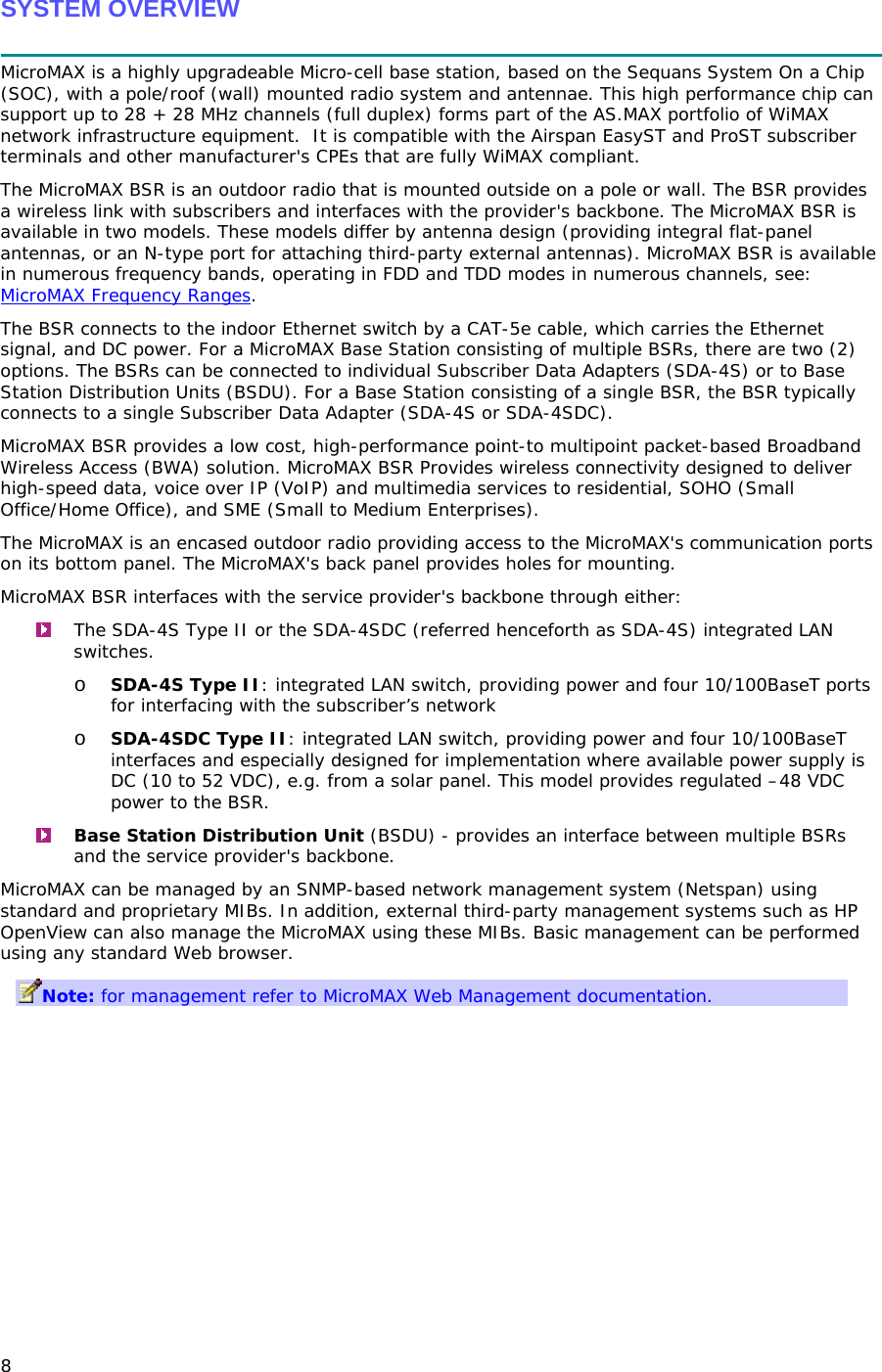
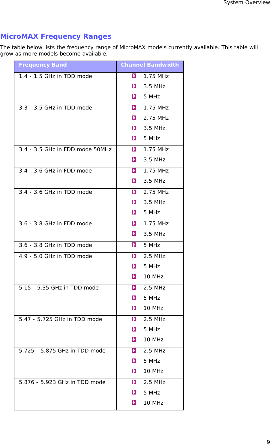
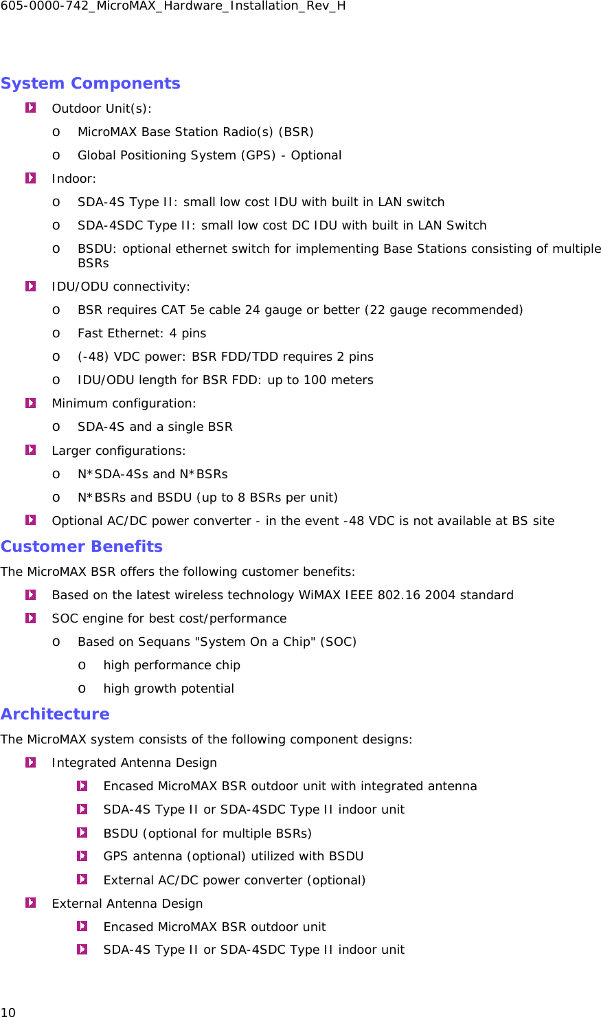
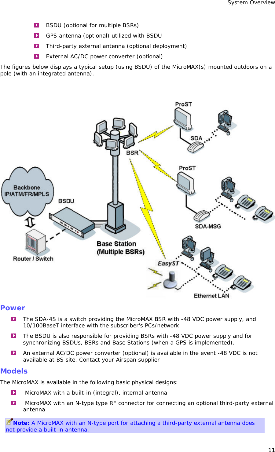
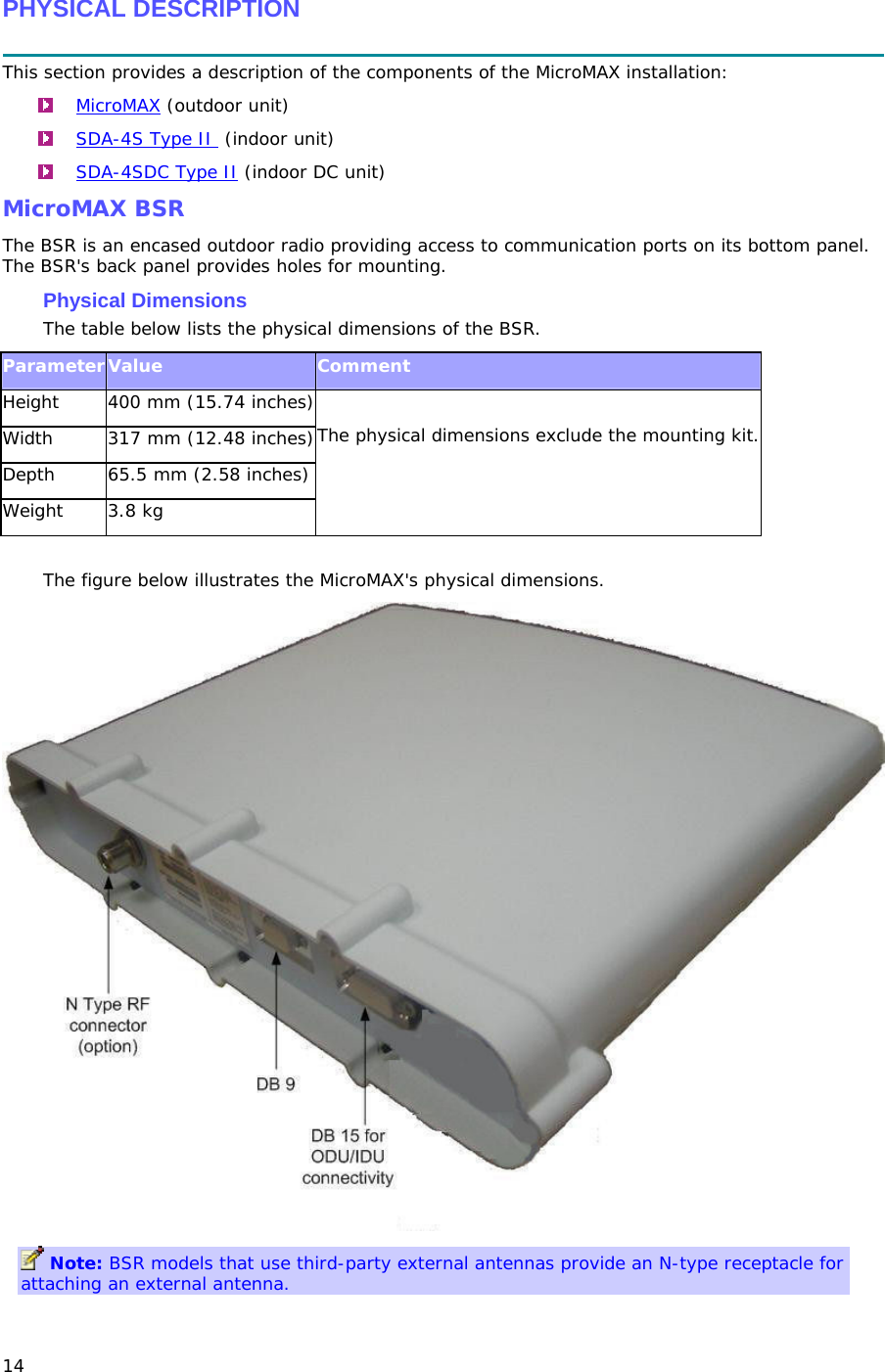
Airspan Networks MMAX37 Base station radio MicroMAX 3.7 GHz TDD User Manual MicroMAX Hardware Installation

Airspan Networks Inc Base station radio MicroMAX 3.7 GHz TDD MicroMAX Hardware Installation

User manual

          IP-based  Broadband Wireless Access (BWA) System   605-0000-742 Rev H      MicroMAX Hardware Installation  SR 6.5                              The Innovation Behind Broadband Wireless Connecting the World
 ii Table Of Contents Introduction.......................................................................................................................1 Purpose..........................................................................................................................1 Targeted Audience ...........................................................................................................1 Referenced Documentation................................................................................................1 Conventions....................................................................................................................1 Warnings and Cautions........................................................................................................2 Human Exposure to Radio Frequencies................................................................................2 Radio Interference ...........................................................................................................2 Avoiding Radio Interference...............................................................................................2 Modifications ...................................................................................................................2 General ..........................................................................................................................2 Manufacturer's Disclaimer Statement ..................................................................................2 DECLARATION OF CONFORMITY............................................................................................4 European Community, Switzerland, Norway, Iceland, and Liechtenstein ...................................4 Declaration of Conformity with Regard to the R&TTE Directive 1999/5/EC.................................4 FCC Notice.........................................................................................................................6 Federal Communication Commission Notice..........................................................................6 GPS Compliance...............................................................................................................6 Maximum Output TX Power ...............................................................................................7 System Overview................................................................................................................8 MicroMAX Frequency Ranges..............................................................................................9 System Components....................................................................................................... 10 Customer Benefits.......................................................................................................... 10 Architecture .................................................................................................................. 10 Power...........................................................................................................................11 Models ......................................................................................................................... 11 Installation Prerequisites.................................................................................................... 12 Package Contents........................................................................................................... 12 Required Tools............................................................................................................... 12 Radio Site Planning ........................................................................................................ 13 Radio Antenna Alignment ............................................................................................. 13 Physical Description .......................................................................................................... 14 MicroMAX BSR............................................................................................................... 14 Physical Dimensions..................................................................................................... 14 Ports ......................................................................................................................... 15 SDA-4S Type II ............................................................................................................. 16 Physical Dimensions..................................................................................................... 16 Ports ......................................................................................................................... 17
Table Of Contents iii LEDs ......................................................................................................................... 17 SDA-4SDC Type II ......................................................................................................... 18 Physical Dimensions..................................................................................................... 18 Ports ......................................................................................................................... 19 LEDs ......................................................................................................................... 19 BSDU Description.............................................................................................................. 21 Physical Dimensions..................................................................................................... 21 Ports ......................................................................................................................... 22 Rear Panel.................................................................................................................. 24 GPS Description................................................................................................................ 25 Physical Dimensions..................................................................................................... 25 Ports ......................................................................................................................... 25 AC/DC power converter ..................................................................................................... 27 Physical Dimensions..................................................................................................... 27 Redundant PS Unit......................................................................................................... 27 Mounting the Base Station Radio (BSR)................................................................................ 28 Mounting the MicroMAX................................................................................................... 28 Pole-Mounting the BSR ................................................................................................... 28 Wall-Mounting the BSR (Optional) .................................................................................... 33 Installing the SDA-4S ..................................................................................................... 36 Wall Mounting............................................................................................................. 36 Mounting the BSDU........................................................................................................... 38 Mounting the BSDU........................................................................................................ 38 Desktop mounting....................................................................................................... 38 Rack mounting............................................................................................................ 38 Mounting the gps.............................................................................................................. 40 Mounting the GPS .......................................................................................................... 40 Mounting AC/DC power converter........................................................................................ 41 Mounting the AC/DC Power Converter ............................................................................... 41 Rack mounting............................................................................................................ 41 Connecting Redundant PS Unit......................................................................................... 41 Cabling the BSR................................................................................................................ 43 Connecting the BSR to the SDA-4S................................................................................... 43 SDA-4S Type II ............................................................................................................. 44 Using the SDA-4S Type II............................................................................................. 44 Connecting the BSR........................................................................................................ 46 Connecting BSR to the BSDU ........................................................................................ 46  Connecting BSDU to Network........................................................................................ 48 Connecting BSDUs....................................................................................................... 48 Connecting BSDU to PC for SNMP Management................................................................ 50
605-0000-742_MicroMAX_Hardware_Installation_Rev_H iv Connecting the sda-4s to the power supply........................................................................... 51 Connecting the SDA-4S Type II........................................................................................ 51 Connecting the SDA-4SDC Type II.................................................................................... 52 Connecting SDA-4S to Ethernet Network ........................................................................... 53 Connecting Power Cable for SDA-4SDC ................................................................................ 54 Power Cable Connection.................................................................................................. 54 Housing the Connectors................................................................................................ 54 Connecting to the SDA-4SDC ........................................................................................ 54 Connecting BSDU to Ac/DC Power converter ......................................................................... 56 Connecting BSDU to AC/DC Power Converter ..................................................................... 56 Required Equipment .................................................................................................... 56 Connections................................................................................................................ 56 Power Cable Assembly ................................................................................................. 57 Housing the Connectors................................................................................................ 57 Cable Connection ........................................................................................................... 58 Connecting lightning and Surge Protector............................................................................. 62 PolyPhaser Wiring Diagrams ............................................................................................ 63 Lightning and Surge Protection Connection Scenarios ....................................................... 65 Connecting third-Party External Antennas............................................................................. 68 Connecting Third Party External Antennas.......................................................................... 68 Connecting GPS Antenna to BSDU .................................................................................... 69 Connecting the GPS..................................................................................................... 69 GPS Alignment............................................................................................................ 72 Trademarks and Copyrights................................................................................................ 73 Environmental.................................................................................................................. 74 Environmental Conditions................................................................................................ 74 BSR and SDA.............................................................................................................. 74 BSDU ........................................................................................................................ 74 Contact Information.......................................................................................................... 75 Revisions......................................................................................................................... 76 Warnings......................................................................................................................... 77 1. Disclaimer................................................................................................................. 77 1.1 Safety Warnings....................................................................................................... 77 1.2 Important Warning Symbols....................................................................................... 77 1.3 Important Service Information.................................................................................... 78 1.4 UL Information......................................................................................................... 78 1.5 CE Notice ................................................................................................................ 78 1.6 European Community, Switzerland, Norway, Iceland, and Liechtenstein............................ 79 Declaration of Conformity with Regard to the R&TTE Directive 1999/5/EC............................ 79 1.7 CAUTION................................................................................................................. 80
Table Of Contents v 1.8 Lightning Protection .................................................................................................. 80 Glossary.......................................................................................................................... 82
   1 INTRODUCTION  Thank you for purchasing Airspan's MicroMAX Base Station Radio. The MicroMAX Base Station Radio (BSR) is part of Airspan's AS.MAX family of WiMAX-based products. This section discusses the purpose, audience, conventions, and customer support of this guide. Purpose This guide provides step-by-step instructions for setting up and installing the MicroMAX BSR.  Targeted Audience This guide is intended for the Airspan technician who is a qualified installer responsible for installing the MicroMAX BSR. Referenced Documentation For a description of the Web-based management tools for configuring and managing MicroMAX BSR, see the following manuals:   MicroMAX Web-based Management User's Guide  Conventions This guide uses the following typographical conventions: Convention   Meaning  Example Bold  Command, icon, button, and field  Click the Next button. "To" in bold face and at the beginning of a sentence  Introduces a numbered procedure  To download a SW file: 1. ...  Note that provides useful information  --  Warning that provides information that can prevent and avoid bodily or mechanical harm --
605-0000-742_MicroMAX_Hardware_Installation_Rev_H 2     WARNINGS AND CAUTIONS  Human Exposure to Radio Frequencies The MicroMAX should be installed and operated from a minimum distance of 36 cm to your body. Radio Interference This equipment generates, uses, and can radiate radio frequency energy and, if not installed and used in accordance with the instructions, may cause harmful interference to radio communications. However, there is no guarantee that interference will not occur in a particular installation. If this equipment does cause harmful interference to radio or television reception, which can be determined by turning the equipment on and off, the user is encouraged to try to correct the interference by performing one or more of the following measures:  Reorientate or relocate the receiving antenna   Increase separation between the equipment and receiver   Connect the equipment to an outlet on a circuit different from that to which the receiver is connected   Consult the dealer or an experienced radio/TV technician for help Avoiding Radio Interference   This transmitter must not be co-located or operating in conjunction with any antenna or transmitter.   Ensure a minimum of 1-meter separation between co-located BSRs. Modifications Any changes and modifications to this device that are not expressly approved by Airspan Networks may void the user's authority to operate the equipment.  General  Only qualified personnel should be allowed to install, replace, and service the equipment.  The device cannot be sold retail, to the general public or by mail order. It must be sold to dealers.  Installation must be controlled.  Installation must be performed by licensed professionals.  Installation requires special training.  The MicroMAX radio and antenna should be installed ONLY by experienced installation professionals who are familiar with local building and safety codes and, wherever applicable, are licensed by the appropriate government regulatory authorities. Failure to do so may void Airspan's AS.MAX product warranty and may expose the end user or the service provider to legal and financial liabilities. Airspan and its resellers or distributors are not liable for injury, damage or violation of regulations associated with the installation of outdoor units or antennas.  Manufacturer's Disclaimer Statement  The information in this document is subject to change without notice and does not represent a commitment on the part of the vendor. No warranty or representation, either expressed or implied, is made with respect to the quality, accuracy or fitness for any particular purpose of this document. The manufacturer reserves the right to make changes to the content of this document and/or the products associated with it at any time without obligation to notify any person or organization of such changes. In no event will the manufacturer be liable for direct, indirect, special, incidental or consequential damages arising out of the use or inability to use
Warnings and Cautions 3 this product or documentation, even if advised of the possibility of such damages. This document contains materials protected by copyright. All rights are reserved. No part of this manual may be reproduced or transmitted in any form, by any means or for any purpose without expressed written consent of its authors. Product names appearing in this document are mentioned for identification purposes only. All trademarks, product names or brand names appearing in this document are registered property of their respective owners.
605-0000-742_MicroMAX_Hardware_Installation_Rev_H 4    DECLARATION OF CONFORMITY  European Community, Switzerland, Norway, Iceland, and Liechtenstein  Declaration of Conformity with Regard to the R&TTE Directive 1999/5/EC  English:  This equipment is in compliance with the essential requirements and other relevant provisions of Directive 1999/5/EC.  Deutsch:  Dieses Gerät entspricht den grundlegenden Anforderungen und den weiteren entsprecheneden Vorgaben der Richtlinie 1999/5/EU.   Dansk:  Dette udstyr er i overensstemmelse med de væsentlige krav og andre relevante bestemmelser i Directiv 1999/5/EF.   Español:  Este equipo cumple con los requisitos esenciales asi como con otras disposiciones de la Directive 1999/5/EC.   Greek:  ΜΕ ΤΗΝ ΠΑΡΟΥΣΑ Airspan ∆ΗΛΩΝΕΙ ΟΤΙ Ο ΕΞΟΠΛΙΣΜΟΣ ΣΥΜΜΟΡΦΩΝΕΤΑΙ ΠΡΟΣ ΤΙΣ ΟΥΣΙΩ∆ΕΙΣ ΑΠΑΙΤΗΣΕΙΣ ΚΑΙ ΤΙΣ ΛΟΙΠΕΣ ΣΧΕΤΙΚΕΣ ∆ΙΑΤΑΞΕΙΣ ΤΗΣ Ο∆ΗΓΙΑΣ 1999/5/ΕΚ.   Français:  Cet appareil est conforme aux exigencies essentialles et aux autres dispositions pertinantes de la Directive 1999/5/EC.   Íslenska:  Þessi búnaður samrýmist lögboðnum kröfum og öðrum ákvæðum tilskipunar 1999/5/ESB.   Italiano:  Questo apparato é conforme ai requisiti essenziali ed agli altri principi sanciti dalla Direttiva 1999/5/EC.   Nederlands:  Deze apparatuur voldoet aan de belangrijkste eisen en andere voorzieningen van richtlijn 1999/5/EC.   Norsk:  Dette utstyret er i samsvar med de grunnleggende krav og andre relevante bestemmelser i EU-directiv 1999/5/EC.   Português:  Este equipamento satisfaz os requisitos essenciais e outras provisões da Directiva 1999/5/EC.   Suomalainen:  Tämä laite täyttää direktiivin 1999/5/EY oleelliset vaatimukset ja on siinä asetettujen muidenkin ehtojen mukainen.   Svenska:
DECLARATION OF CONFORMITY 5 Denna utrustning är i överensstämmelse med de väsentliga kraven och andra relevanta bestämmelser i Direktiv 1999/5/EC.  The Declaration of Conformity related to this product can be obtained from product_management@Airspan.com
605-0000-742_MicroMAX_Hardware_Installation_Rev_H 6     FCC NOTICE  Federal Communication Commission Notice This equipment has been tested and found to comply with the limits for a Class B digital device, pursuant to Part 15 of the FCC Rules. These limits are designed to provide reasonable protection against harmful interference when the equipment is operated in a commercial environment. This equipment generates, uses, and can radiate radio frequency energy and, if not installed and used in accordance with the instruction manual, may cause harmful interference to radio communications. Operation of this equipment in a residential area is likely to cause harmful interference in which case the user will be required to correct the interference at his/her own expense. If this equipment does cause harmful interference to radio or television reception, which can be determined by turning the equipment off and on, the user is encouraged to try to correct the interference by one or more of the following measures:  Reorient or relocate the receiving antenna.  Increase the separation between the equipment and receiver.  Connect the equipment into an outlet on a circuit different from that to which the receiver is connected.  Consult the dealer or an experienced radio/TV technician for help. GPS Compliance  The GPS is in compliance with the essential requirements and other relevant provisions of Directive 1999/5/EC." The GPS complies with the following EMC Common Regulatory Testing standards:  EN55022: Radiated and Conducted Emissions  CISPR 22: Class B  EN 50081-1: Generic Emissions Class B  EN 50082-1: Generic Immunity Class B  EN 61000-4-2: Electrostatic Discharge Immunity  EN 61000-4-3: Radiated RF EM Field Immunity Test  EN 61000-4-4: Electrical Fast Transient/Burst Test  EN 61000-4-6: Conducted Immunity  EN 61000-4-8: Magnetic Field Immunity Note: A GPS is required for synchronizing between multiple Base Stations that implement frequency hopping for wireless communication.
FCC Notice 7  Maximum Output TX Power MicroMAX Maximum Output TX Power  Caution: Do not set maximum output TX power to higher than local regulations.
 8    SYSTEM OVERVIEW  MicroMAX is a highly upgradeable Micro-cell base station, based on the Sequans System On a Chip (SOC), with a pole/roof (wall) mounted radio system and antennae. This high performance chip can support up to 28 + 28 MHz channels (full duplex) forms part of the AS.MAX portfolio of WiMAX network infrastructure equipment.  It is compatible with the Airspan EasyST and ProST subscriber terminals and other manufacturer's CPEs that are fully WiMAX compliant. The MicroMAX BSR is an outdoor radio that is mounted outside on a pole or wall. The BSR provides a wireless link with subscribers and interfaces with the provider's backbone. The MicroMAX BSR is available in two models. These models differ by antenna design (providing integral flat-panel antennas, or an N-type port for attaching third-party external antennas). MicroMAX BSR is available in numerous frequency bands, operating in FDD and TDD modes in numerous channels, see: MicroMAX Frequency Ranges. The BSR connects to the indoor Ethernet switch by a CAT-5e cable, which carries the Ethernet signal, and DC power. For a MicroMAX Base Station consisting of multiple BSRs, there are two (2) options. The BSRs can be connected to individual Subscriber Data Adapters (SDA-4S) or to Base Station Distribution Units (BSDU). For a Base Station consisting of a single BSR, the BSR typically connects to a single Subscriber Data Adapter (SDA-4S or SDA-4SDC).  MicroMAX BSR provides a low cost, high-performance point-to multipoint packet-based Broadband Wireless Access (BWA) solution. MicroMAX BSR Provides wireless connectivity designed to deliver high-speed data, voice over IP (VoIP) and multimedia services to residential, SOHO (Small Office/Home Office), and SME (Small to Medium Enterprises). The MicroMAX is an encased outdoor radio providing access to the MicroMAX's communication ports on its bottom panel. The MicroMAX's back panel provides holes for mounting. MicroMAX BSR interfaces with the service provider's backbone through either:  The SDA-4S Type II or the SDA-4SDC (referred henceforth as SDA-4S) integrated LAN switches. o SDA-4S Type II: integrated LAN switch, providing power and four 10/100BaseT ports for interfacing with the subscriber’s network o SDA-4SDC Type II: integrated LAN switch, providing power and four 10/100BaseT interfaces and especially designed for implementation where available power supply is DC (10 to 52 VDC), e.g. from a solar panel. This model provides regulated –48 VDC power to the BSR.  Base Station Distribution Unit (BSDU) - provides an interface between multiple BSRs and the service provider's backbone. MicroMAX can be managed by an SNMP-based network management system (Netspan) using standard and proprietary MIBs. In addition, external third-party management systems such as HP OpenView can also manage the MicroMAX using these MIBs. Basic management can be performed using any standard Web browser. Note: for management refer to MicroMAX Web Management documentation.
System Overview 9  MicroMAX Frequency Ranges The table below lists the frequency range of MicroMAX models currently available. This table will grow as more models become available. Frequency Band  Channel Bandwidth 1.4 - 1.5 GHz in TDD mode   1.75 MHz   3.5 MHz  5 MHz 3.3 - 3.5 GHz in TDD mode   1.75 MHz   2.75 MHz  3.5 MHz  5 MHz 3.4 - 3.5 GHz in FDD mode 50MHz   1.75 MHz  3.5 MHz 3.4 - 3.6 GHz in FDD mode   1.75 MHz  3.5 MHz 3.4 - 3.6 GHz in TDD mode   2.75 MHz  3.5 MHz  5 MHz 3.6 - 3.8 GHz in FDD mode   1.75 MHz  3.5 MHz 3.6 - 3.8 GHz in TDD mode   5 MHz 4.9 - 5.0 GHz in TDD mode   2.5 MHz  5 MHz  10 MHz 5.15 - 5.35 GHz in TDD mode   2.5 MHz  5 MHz  10 MHz 5.47 - 5.725 GHz in TDD mode   2.5 MHz  5 MHz  10 MHz 5.725 - 5.875 GHz in TDD mode   2.5 MHz  5 MHz  10 MHz 5.876 - 5.923 GHz in TDD mode   2.5 MHz  5 MHz  10 MHz
605-0000-742_MicroMAX_Hardware_Installation_Rev_H 10     System Components  Outdoor Unit(s): o MicroMAX Base Station Radio(s) (BSR) o Global Positioning System (GPS) - Optional   Indoor: o SDA-4S Type II: small low cost IDU with built in LAN switch o SDA-4SDC Type II: small low cost DC IDU with built in LAN Switch o BSDU: optional ethernet switch for implementing Base Stations consisting of multiple BSRs  IDU/ODU connectivity: o BSR requires CAT 5e cable 24 gauge or better (22 gauge recommended) o Fast Ethernet: 4 pins o (-48) VDC power: BSR FDD/TDD requires 2 pins o IDU/ODU length for BSR FDD: up to 100 meters  Minimum configuration: o SDA-4S and a single BSR  Larger configurations: o N*SDA-4Ss and N*BSRs o N*BSRs and BSDU (up to 8 BSRs per unit)  Optional AC/DC power converter - in the event -48 VDC is not available at BS site Customer Benefits The MicroMAX BSR offers the following customer benefits:  Based on the latest wireless technology WiMAX IEEE 802.16 2004 standard  SOC engine for best cost/performance o Based on Sequans "System On a Chip" (SOC) o high performance chip o high growth potential Architecture The MicroMAX system consists of the following component designs:  Integrated Antenna Design  Encased MicroMAX BSR outdoor unit with integrated antenna  SDA-4S Type II or SDA-4SDC Type II indoor unit  BSDU (optional for multiple BSRs)  GPS antenna (optional) utilized with BSDU  External AC/DC power converter (optional)  External Antenna Design  Encased MicroMAX BSR outdoor unit  SDA-4S Type II or SDA-4SDC Type II indoor unit
System Overview 11  BSDU (optional for multiple BSRs)  GPS antenna (optional) utilized with BSDU  Third-party external antenna (optional deployment)  External AC/DC power converter (optional) The figures below displays a typical setup (using BSDU) of the MicroMAX(s) mounted outdoors on a pole (with an integrated antenna).    Power  The SDA-4S is a switch providing the MicroMAX BSR with -48 VDC power supply, and 10/100BaseT interface with the subscriber's PCs/network.  The BSDU is also responsible for providing BSRs with -48 VDC power supply and for synchronizing BSDUs, BSRs and Base Stations (when a GPS is implemented).  An external AC/DC power converter (optional) is available in the event -48 VDC is not available at BS site. Contact your Airspan supplier Models The MicroMAX is available in the following basic physical designs:    MicroMAX with a built-in (integral), internal antenna   MicroMAX with an N-type type RF connector for connecting an optional third-party external antenna  Note: A MicroMAX with an N-type port for attaching a third-party external antenna does not provide a built-in antenna.
 12    INSTALLATION PREREQUISITES  Before installing your MicroMAX, review:  Package contents  Required tools  Radio Site planning Package Contents Examine the AS.MAX shipping container. If you notice any damage, or missing items as listed in the Packing List, immediately notify the carrier that delivered the unit and contact a Airspan representative. The MicroMAX kit should contain the following items:  MicroMAX Base Station radio  DB15-to-RJ45 adapter for plugging into the BSR's 15-pin D-type port  Pole-mounting kit: o 2 x M10 hex head screws o 2 x M10 flat washers o 2 x M10 spring lock washers o 2 x M10 hex nuts o Mounting bracket o 2 x M6 hex head screws o 2 x M6 spring lock washers o Clamping bracket o 2 x M8 'U'- bolts o 4 x M8 hex nuts o 4 x M8 plain washers o 4 x M8 spring lock washers The GPS (optional) kit should contain the following items:  GPS Smart Antenna RS422  Conn DB15PM AMP - for discrete wires IDC  Connector, Circular (Deutsch IMC26-2212X) - Industrial Micro 12P F  Cable 4x2422# (Teldor) - 10 meters  8x Contact sockets (for Deutsch 6862-20122278) - Circular Micro connectors  Boot shrink w/ glue (Raychem) - heat shrink  Plastic Hood 15-Pin - D-Type sub-connector Note: The standard MicroMAX kit does not include wall-mounting accessories. For pricing and ordering of wall-mounting accessories, please contact your nearest Airspan dealer. Required Tools The following tools are required to install the MicroMAX unit:  Torque wrench for N-type connectors (only relevant when implementing external antenna)  Cable stripping tool
Getting Started 13  10-, 13-, and 17-mm A/F open ended spanners Radio Site Planning Proper site selection and planning before installing your MicroMAX will ensure a successful deployment of your AS.MAX system. A summary of the main site planning considerations is provided below:  Minimum obstructions (e.g. buildings) in the radio path between base station and the subscriber terminals  Mount radio as high as possible to avoid obstructions in the wireless path  Check possibility of future obstructions such as plans to erect buildings and trees that may grow tall enough to obstruct the wireless path  Align radio for maximizing received signal strength (RSS)   Consider nearby sources of interference that could degrade performance of radio  Mount radio as far from sources of interference as possible  Ensure base station and subscriber terminals (i.e ProST/EasyST) are within maximum coverage range of reception  Maximum standard CAT-5e cable length connecting the MicroMAX to the indoor SDA-4S or BSDU is 100 meters   Ensure that you have sufficient wiring conduit and cable ties to channel and protect the CAT 5e cable connecting the outdoor MicroMAX to the indoor SDA-4S Radio Antenna Alignment ProST Once the subscriber unit (i.e. ProST) is installed and aimed in the general direction of the BSR, it is recommended to measure the received signal strength (RSS) to determine the signal strength received from the BSR, and to precisely align the ProST for maximum signal strength. You need to orientate (up/down, left/right) the ProST until the maximum RSSI levels are achieved, and then secure the ProST. EasyST Once the subscriber unit (i.e. EasyST) is installed and aimed in the general direction of the BSR, simply move the EasyST to the position that gives optimal reception.
 14    PHYSICAL DESCRIPTION  This section provides a description of the components of the MicroMAX installation:  MicroMAX (outdoor unit)  SDA-4S Type II  (indoor unit)  SDA-4SDC Type II (indoor DC unit) MicroMAX BSR The BSR is an encased outdoor radio providing access to communication ports on its bottom panel. The BSR's back panel provides holes for mounting. Physical Dimensions The table below lists the physical dimensions of the BSR. ParameterValue  Comment Height  400 mm (15.74 inches)Width  317 mm (12.48 inches)Depth  65.5 mm (2.58 inches) Weight 3.8 kg  The physical dimensions exclude the mounting kit. The figure below illustrates the MicroMAX's physical dimensions.   Note: BSR models that use third-party external antennas provide an N-type receptacle for attaching an external antenna.
Physical Description 15  Ports The table below defines the different ports on the bottom panel. Port interfaces  Description DB 15  IDU/ODU interface:  Fast Ethernet from/to SDA-4S or SDA-4SDC Type II and BSDU  Power from SDA-4S Type II or SDA-4SDC Type II and BSDU  TDD Tx/Rx sync from BSDU DB 9  Engineering applicability (Technical Service only) N Type RF connector - relevant when implementing external antenna  External antenna connection Note: Some previous models (still in use) have an RJ45 port with cover which has been discontinued as of December 2006.
605-0000-742_MicroMAX_Hardware_Installation_Rev_H 16     MicroMAX is powered from the indoor integrated LAN switch: Note: The SDA-4S Type II and the SDA-4SDC are physically (externally) the same other than the power socket. SDA-4S Type II The SDA-4S Type II indoor unit (hereafter referred to as SDA-4S) is an integrated LAN switch, providing power and four 10/100BaseT ports for interfacing with the subscriber’s network. The unit is displayed in the figure below.  This subsection provides the following SDA-4S physical descriptions:  Dimensions  Ports  LEDs Physical Dimensions The SDA-4S physical dimensions are described in the table below: Parameter  Value Dimensions  Height - 200mm (7.87 inches) Width - 150mm (5.9 inches) Depth - 40mm (1.57 inches) Weight  0.53 Kg
Physical Description 17  Ports The SDA-4S adapter provides ports on the front panel, which are described in the table below: Port  Interface 4 x 8-pin RJ-45  10/100BaseT with subscriber's network (supports Auto Negotiation and MDI/MDI-X automatic crossover, allowing connection of straight-through or crossover cables) 15-pin D-type (female)  10/100BaseT with BSR AC power socket  Subscriber's power outlet (110-240 VAC, 1A, 50/60 Hz, 50W) Note: The ports of the SDA-4S models support Auto Negotiation, allowing automatic configuration for the highest possible speed link (10BaseT or 100BaseT), and Full Duplex or Half Duplex mode. In other words, the speed of the connected device (e.g. PC) determines the speed at which packets are transmitted through the specific SDA-4S port. In addition, the SDA-4S ports support MDI/MDI-X automatic crossover, allowing connection to straight-through or crossover cables. LEDs The LEDs description is the same as for the SDA-4SDC below.
605-0000-742_MicroMAX_Hardware_Installation_Rev_H 18     SDA-4SDC Type II The SDA-4SDC Type II indoor unit is an integrated LAN switch, providing power and four 10/100BaseT ports for interfacing with the subscriber’s network and especially designed for implementation where available power supply is DC.  This model provides regulated –48 VDC power. The unit is displayed in the figure below.  This subsection provides the following SDA-4SDC physical descriptions:  Dimensions  Ports  LEDs Physical Dimensions The SDA-4SDC physical dimensions are described in the table below: Parameter  Value Dimensions  Height - 200mm (7.87 inches) Width - 150mm (5.9 inches) Depth - 40mm (1.57 inches) Weight  0.53 Kg
Physical Description 19  Ports The SDA-4SDC adapter provides ports on the front panel, which are described in the table below: Port  Interface 4 x 8-pin RJ-45  10/100BaseT with subscriber's network (supports Auto Negotiation and MDI/MDI-X automatic crossover, allowing connection of straight-through or crossover cables) 15-pin D-type (female)  10/100BaseT with BSR DC power socket  DC power outlet (10-52 VDC, 24W)  LEDs The SDA-4S all types adapter provides LED indicators on the top panel, which are described in the table below: LED  Color  Status  Description On  Physical link (10BaseT or 100BaseT) between SDA-4S adapter and BSR Blinking  Traffic currently flowing between SDA-4S and BSR UPLINK Yellow (100BaseT) or Orange (10BaseT) Off  No link between SDA-4S and BSR On  Physical link (10BaseT or 100BaseT) between SDA-4S and subscriber's Ethernet network Blinking  Traffic currently flowing between SDA-4S and subscriber's Ethernet network 1, 2, 3, 4  Yellow (100BaseT) or Orange (10BaseT) Off  No link between SDA-4S and subscriber's Ethernet network On  Power received by SDA-4S POWER Green Off  No power received by SDA-4S  The figure below displays the LEDs which are located on the top panel of the SDA-4S adapter:
605-0000-742_MicroMAX_Hardware_Installation_Rev_H 20
   21 BSDU DESCRIPTION  This section provides a description of the Base Station Distribution Unit (BSDU).  The BSDU is connected to the BSRs by standard CAT-5e cables. Each BSDU can service a maximum of 8 BSRs. In addition, up to two BSDUs can be daisy-chained at a Base Station, supporting up to 16 BSRs. Therefore, a Base Station at maximum configuration can serve up to 8192 subscribers (i.e. 16 BSRs multiplied by 512 subscribers). The BSDU provides a 15-pin D-type port for interfacing with the BSRs, for convenience, a DB15-to-RJ45 adapter is supplied for attaching to the 15-pin D-type port to allow the use of RJ-45 connectors for outdoor-to-indoor CAT-5e connectivity.  The AS.MAX Base Station Distribution Unit (BSDU) provides an interface between multiple MicroMAX (BSRs) and the service provider’s backbone. The BSDU provides the following functionalities:  Data switching and aggregation:  o Data switching between up to eight MicroMAX BSRs over 10/100 BaseT interface o Aggregate the MicroMAX BSRs data via two 1000BaseT Ethernet (GE) ports towards the backhaul/backbone or to cascade to another BSDU  Synchronization:  o Tx / Rx TDD synchronization for multiple MicroMAX BSRs per BSDU and between connected BSDUs  o GPS for TDD Tx / Rx synchronization of different BS sites  Power distribution o Provides DC power from a single 48 VDC source to eight MicroMAX BSRs o AC/DC power converter (optional) - in the event -48 VDC is not available at BS site Note: The unit should be powered by 48Vdc (40-54Vdc), 4.5A from safety approved power supply that its output is SELV and is separated from mains by minimum double/reinforced insulation. Physical Dimensions The table below lists the physical dimensions of the BSDU. ParameterValue  Comment Height  43.2 mm (1.7 inches) Width  482.6 mm (19 inches) Depth  228.6 mm (9 inches) Weight 2.9 kg  The physical dimensions exclude the bracket flanges for mounting.
605-0000-742_MicroMAX_Hardware_Installation_Rev_H 22    The figure below illustrates the BSDU's physical dimensions.   Ports The BSDU provides various hardware interfaces on its front and rear panel as described in the tables and figures below. Front Panel  The following table lists the front panel hardware interfaces (refer to the front panel figure):   Ports Description Port  Label  Interface 8-pin RJ-45 (4)  10/100  4 x 10/100 BaseT general purpose switch 8-pin RJ-45  MNG  10/100 BaseT for out-of-band management 8-pin RJ-45 (2)  10/100/1000 1 / 2  1 - Interface with provider’s backbone  2 – Daisy-chained BSDUs, interface with another BSDU for cascading SMA (2)  GPS 10MHz IN & 1PPS IN Interface with GPS for global clock synchronization by means of 2 signals: 10 MHz and 1 PPS For future use SMA (2)  CASCADE 10MHz & 1PPS  Interfaces with a daisy-chained BSDU for cascading the 2 GPS signals For future use 8-pin RJ-45  GPS COM  Interfaces with the GPS serial port for getting status and alarms 8-pin RJ-45  CONSOLE  BSDU serial port for initial configuration Power Receptacle  -48VDC  -48 VDC supply from external feeding source
BSDU Description 23  The BSDU provides LEDs for indicating the status of various operations. The LEDs are located on the front panel. The LEDs colors are green with 3 optional states: Off, On and Flashing. The following table details the LEDs functionality:   LEDs Description LED  Status  Description On  BSR is connected when the link is On (100 Base-T) BSR Status 10/100 (1–8)  Off  BSR is connected when the link is On (10 Base-T) On  Physical link exists between BSDU and BSR Flashing  Ethernet activity detected on BSR port BSR Status LNK/ACT (1–8) Off  No physical link exists between BSDU and BSR On  Power supplied to BSDU’s BSR port BSR Status Power (1–8)  Off  BSDU’s BSR port is disabled by software, or port failure has occurred Load Indicator  8 levels of On  The Traffic Load Bar indicates 8 traffic levels via 8 LEDs: No. of LEDs  Utilization 1 0.4% 2 0.8% 3 1.6% 4 3.2% 5 6.4% 6 12.8% 7 25% 8  Over than 50%  On  Viable physical link between the 10/100 Base-T port and the external device to which this port connects Flashing  Ethernet activity detected on 10/100 Base-T port General Purpose Switch LNK/ACT (1–5)  Off  No physical link between 10/100 Base-T port and external deviceto which this port connects On  The link between the general purpose switch port and the external device is synchronized with a rate of 100 Base-T General Purpose Switch 10/100 (1–5)  Off  The link between the general purpose switch port and the external device is synchronized with a rate of 10 Base-T On  Viable physical link between the 10/100/1000 Base-T port towards the backhaul or the daizy-chained BSDU Flashing  Ethernet activity detected on 10/100 Base-T port GE Ports Status Backhaul / Cascade LNK/ACT (1–2)  Off  No physical link between the 10/100/1000 Base-T port towards the backhaul or the daizy-chained BSDU GE Ports Status Backhaul / On  The link between the GE port and the backhaul or the daizy-chained BSDU is synchronized with a rate of 100 Base-T
605-0000-742_MicroMAX_Hardware_Installation_Rev_H 24    Off  The link between the GE port and the backhaul or the daizy-chained BSDU is synchronized with a rate of 10 Base-T On  The link between the GE port and the backhaul or the daizy-chained BSDU is synchronized with a rate of 1000 Base-T GE Ports Status Backhaul / Cascade 1000 (1–2) Off  The link between the GE port and the backhaul or the daizy-chained BSDU is not synchronized with a rate of 1000 Base-T On  Master provides the GPS clock source in case of BSDUs cascading GPS Status Master Off  Slave gets the GPS clock from the Master BSDU in case of BSDUs cascading On  GPS is connected GPS Status GPS Off  No GPS is connected Flashing  When the GPS sync pulse is received GPS Status SYNC Off  No GPS sync pulse Power  On  Indicates whether the BSDU gets the -48 VDC from external source  Rear Panel  The following table lists the rear panel hardware interfaces (refer to the rear panel figure): Port  Label  Interface 15-pin D-type female (8)  BSR 1 – BSR 8  Provides 10/100 Base-T (Ethernet),synchronization and 48 VDC power feed interfaces with BSRs 25-pin D-type female  External Power Supply  For external Power Supply (AC/DC)  management 15-pin D-type female (1)  GPS Global Positioning System (GPS)-based synchronization
   25 GPS DESCRIPTION  This section provides a description of the Global Positioning System (GPS) - Optional. The third-party GPS antenna is a rugged, self-contained GPS receiver and antenna that receives a universal GPS satellite clock signal. The GPS is an optional unit that connects to the BSDU. The GPS synchronizes (based on frequency hopping) multiple Base Stations, ensuring that the entire AsMAX network operates with the same clock based on a universal satellite clock signal. This is crucial in eliminating radio frequency ghosting effects. GPS antenna   Physical Dimensions The GPS physical dimensions are described in the following table. ParameterValue Diameter  5.91" (15.0 cm)Height  6.5" (16.5 cm) Weight  684g (1.51 lb)  The figure below illustrates the GPS's physical dimensions.  GPS antenna dimensions – side view   Ports The GPS provides 12-pin male contacts for connecting a cable between it and the BSDU.
605-0000-742_MicroMAX_Hardware_Installation_Rev_H 26    GPS Pinouts  D15 ConnectorGPS connector13 1 6 2 5 3 4 4 3 5 -- 6(NC) -- 7(NC) -- 8(NC) 12 9  10(NC) 7 11 8 12
   27 AC/DC POWER CONVERTER  This section provides a description of the external AC/DC Power converter - Optional. The third-party external AC/DC Power Converter is an optional unit that connects to the BSDU in the event there is no -48VDC availability at the Base Station site. The AC/DC Power Converter chassis fitted with one PS Unit for BSDU (PC-BSDU-1) supports up to 8 BSRs. An additional PS unit is available (optional) for redundancy. The figure below illustrates the AC/DC Power Converter's physical dimensions. AC/DC Power Converter  Physical Dimensions The AC/DC power converter physical dimensions are described in the following table. ParameterValue  Comment Height  43.2 mm (1.7 inches) Width  482.6 mm (19 inches) Depth  228.6 mm (9 inches)  The physical dimensions exclude the bracket flanges for mounting.  Redundant PS Unit The RPSU-BSDU-1 is a redundant PS Unit for the BSDU AC/DC power converter. The power factor corrected (PFC) front ends provide a 48 VDC output for distributed power applications. The small 1U by 2U size allows for configurations of either height in hot-swap redundant systems while its internal fan and cooling design permits wide use with reliable operation. The figure below illustrates the redundant PS Unit.
 28    MOUNTING THE BASE STATION RADIO (BSR)  Mounting the MicroMAX The MicroMAX BSR can be pole-mounted or wall-mounted (optional). Pole mounting allows the BSR to be easily adjusted in the horizontal (azimuth) and vertical (elevation) planes for antenna alignment. For either mounting method, the MicroMAX provides mounting holes (displayed in the figure below), molded into its back panel for attaching the mounting brackets. Note: The BSR fully complies with IP Code - IPX6 for product enclosure protection.   Warning: The BSR device is an outdoor radio unit, and therefore, must only be mounted outside.   Warning: Mount the MicroMAX in an orientation such that its ports (located on the bottom panel) faces downwards. This prevents rain water from settling on the ports, and thereby, avoiding damage to the unit such as corrosion and electrical short-circuiting.  Note: The standard BSR kit, provides pole-mounting brackets. If you want to wall-mount the MicroMAX, contact your Airspan distributor for pricing and ordering of wall-mounting brackets.  Pole-Mounting the BSR Pole mounting allows the MicroMAX to be easily adjusted in the horizontal (azimuth) and vertical (elevation) planes for antenna alignment. The BSR is mounted using the mounting holes located on the BSR's back panel and the supplied pole-mounting brackets. The pole-mounting bracket is designed to support the BSR on a round pole of 45 mm in diameter. The figure below summarizes of the MicroMAX's pole-mounting procedure.
Mounting the Base Station Radio (BSR) 29  To pole mount the MicroMAX BSR: 1. Attach the mounting bracket to the MicroMAX: a. Align the mounting bracket with the MicroMAX's mounting holes so that the mounting bracket's side with the built-in nut is aligned with the BSR's mounting holes furthest from the MicroMAX's bottom panel, as shown in the figure below. b. Slide an M10-flat washer and M10-spring lock washer onto an M10-hex head screw (ensure spring lock washer is closest to the bolt's head). From the external side, insert the M10-hex head screw through the mounting bracket and MicroMAX's mounting holes. Fasten the M10-hex head screw (one is provided with a built-in nut while the other requires you to insert an M10-hex nut into the MicroMAX's mounting hole).
605-0000-742_MicroMAX_Hardware_Installation_Rev_H 30     2. Attach the clamping bracket to the mounting bracket: a. Slide an M6-spring lock washer onto an M6-hex head screw. Align the mounting bracket's and clamping bracket's pivot holes, such that the clamping bracket is aligned to the inside of the mounting bracket. From the external side of the mounting bracket, insert the M6-hex head screw into the pivot holes and then fasten, but not tightly. (The clamping bracket provides a built-in nut.) b. Choose an elevation hole on the mounting bracket and then align it with the corresponding hole on the clamping bracket. Slide an M6-spring lock washer onto an M6-hex head screw, and then from the external side of the mounting bracket, insert the M6-hex head screw through the elevation hole on the mounting bracket and into the clamping bracket's corresponding hole. Fasten but not tightly the M6-hex head screw (the clamping bracket provides built-in nut). The elevation hole can later be changed according to desired antenna orientation in the elevation plane.
Mounting the Base Station Radio (BSR) 31  3. Attach the U-bolt to the pole: a. Place one U-bolt around the pole, and then insert the U-bolt screw side through the two corresponding holes (horizontally parallel) on the clamping bracket. Slide an M8-flat washer and M8-spring lock washer onto each U-bolt screw side (ensure that the flat washer is adjacent to the clamping bracket). Fasten each U-bolt side with the two M8-hex nuts.  b. Attach the second U-bolt as described above.  4. Perform final MicroMAX orientation: a. Adjust the vertical position of the MicroMAX by choosing a final elevation hole as described in Step 2. Lock the MicroMAX at the desired position by inserting the locking bolt in the desired position and fastening it tightly. Fasten tightly the bolt in the pivot hole. The figure below illustrates the angles (in degrees) of each elevation hole.  As
605-0000-742_MicroMAX_Hardware_Installation_Rev_H 32    shown, the MicroMAX pole-mounting bracket allows elevation between -18.5° and 26.3°.  b. Adjust the horizontal position of the MicroMAX by rotating it about the pole, and then tightening the nuts of the U-bolts. Note: A thread-locking compound must be used to prevent the bolts from working loose.  MicroMAX positioning is obtained in two planes by adjustment of the mounting bracket assembly as shown below.       It is important to provide strain relief and drip loop for Cat-5 cables. Create a drip loop and strain relief using cable tie, to tie cable to pole, as displayed in the figure below:
Mounting the Base Station Radio (BSR) 33   Wall-Mounting the BSR (Optional) Note:  The standard BSR kit provides pole-mounting brackets. If you want to wall-mount the MicroMAX BSR contact your Airspan distributor for pricing and ordering of wall-mounting brackets.  Note: A minimum of 3-meter separation is required between mounted MicroMAX's and existing customer radio equipment when transmitting on different sectors (see figure below). However, only a 1-meter separation is required between MicroMAX's when on the same sector and transmitting to the same base station radio without requiring shielding. The figure below illustrates the minimum separation between mounted MicroMAX's when transmitting on different sectors:  MicroMAX wall mounting consists of two main stages:  Attaching the mounting bracket to the MicroMAX's mounting holes  Attaching the mounting bracket (already attached to the MicroMAX) to the wall (or pole) To wall mount the MicroMAX: 1. Position the unassembled mounting bracket on the mounting surface (e.g. wall), and then use a pencil to mark the position of the four mounting holes. Ensure that the distance between the hole centers are 120 mm (height) and 60 mm (width), as displayed in the figure below showing the MicroMAX's fixing dimensions.
605-0000-742_MicroMAX_Hardware_Installation_Rev_H 34     2. Drill holes for each hole that you marked in the step above. 3. Insert wall anchors (not supplied) into each of the drilled holes. 4. Align the mounting bracket's four holes with the wall anchors, and then insert a screw (not supplied) through the mounting bracket holes into each wall anchor, and then tighten. Note: Airspan does not provide screws for attaching the mounting bracket to the wall. The screw size depends on the structure of the building to which the bracket is to be attached. When selecting screw sizes, consideration must be given to the weight of the MicroMAX and load that may be induced in windy conditions.
Mounting the Base Station Radio (BSR) 35  5. Attach the MicroMAX to the mounting bracket by performing the following: a. Slide an M10-spring lock washer and then an M10-plain washer onto each M10-hex head screw (ensure lock washer is nearest to head of screw bolt). b. Align the mounting bracket's holes with the MicroMAX's mounting holes as displayed below. (The mounting bracket side that provides a groove for inserting a nut must be aligned with the MicroMAX's mounting hole that is nearest to the MicroMAX's bottom panel.) c. From the external sides, insert the M10-hex head screws through the mounting bracket's holes and MicroMAX's mounting holes. Loosely fasten with the M10-hex nuts.
605-0000-742_MicroMAX_Hardware_Installation_Rev_H 36    6. Adjust the horizontal positioning of the MicroMAX (see "Web-Based Management" for MicroMAX antenna alignment using RSS measurements), and then tighten the two M10-hex head screws with the M10 hex nuts. Note: A third-party thread-locking compound must be applied to the M10-hex head screws to prevent the bolts from working loose.  Note: For wall mounting, rotation is restricted in the horizontal plane only.  Installing the SDA-4S The SDA-4S Type II (or SDA-4SDC Type II) is mounted vertically on a wall.  Wall Mounting Wall mounting is made possible by the existence of two mounting hooks molded into the SDA-4S's bottom panel, as displayed in the figure below.
Mounting the Base Station Radio (BSR) 37  To wall mount the SDA-4S: 1. On the wall, mark the position of the two mounting hooks. The dimensions of the wall-mounting hooks are displayed in the template below.  2. Drill holes for each hole that you marked in the step above. 3. Insert wall anchors (supplied) into each of the drilled holes. 4. Insert the 9-inch screws (supplied) into the wall anchors. Ensure at least 2 mm of the screw is exposed to allow insertion into the SDA-4S mounting holes. 5. Hold the SDA-4S with both hands, and align the entrance to the two mounting hooks with the screws. Slide the screws into the mounting hooks, by lowering the SDA-4S onto the screws. Note:  For safety, both mounting hooks must be utilized when mounting the unit.  Note:  The SDA-4S is supplied with a 1-metre AC power lead assembly. Therefore, ensure the unit is mounted within reachable distance to the customer's mains power outlet.  Note:  The maximum cable run between SDA-4S and MicroMAX is 100 meters. Therefore, ensure the unit is mounted within reachable distance.
 38     MOUNTING THE BSDU  Mounting the BSDU The BSDU can be mounted in either of the two (2) following ways:   Horizontally on a desktop  Horizontally in a rack (ETSI or 19“)  Desktop mounting The BSDU can simply be placed horizontally on a table. You can attach to the BSDU's bottom panel, four rubber feet (pads) (supplied) on each corner to provide cushioning and insulation from static electricity. Warning: To prevent a fire hazard caused by overheating, do not place the BSDU on a surface where airflow is restricted. Rack mounting The BSDU is designed for mounting in a standard 19-inch (48.3 cm) ETSI equipment rack or telco rack with 1-rack unit (1-U) of vertical rack space. Mounting bracket flanges are provided for mounting the BSDU into the cabinet, in its kit. Therefore, all that is required for mounting the BSDU is to attach the BSDU front-rail mounting brackets to the rack's mounting rails using the supplied four M5-mounting screws and plastic cup washers. To rack-mount the BSDU: 1. Determine the rack rail holes (left and right side) that will be used for attaching the chassis. 2. Insert four nuts into the rack's rail holes you designated in Step 1. These nuts are housed in Tinnerman clips, which allow you to fasten them into the rail holes. To insert the Tinnerman clips, hold the clips, squeeze them, and then insert them into the rail hole. 3. Carefully insert the BSDU into the rack, aligning the BSDU's mounting bracket holes with the rack rail holes. 4. Insert the M5-mounting screws, with plastic washers, into the BSDU mounting bracket holes, on each side, as shown in figure below. In this way, the chassis is supported until you tighten the chassis screws. 5. Tighten the M5-mounting screws to fasten the chassis to the cabinet.
Mounting the BSDU 39 Note: When mounting multiple BSDUs in a cabinet, vertical spacing (above and below) is required for feeding cables to the rear.  Note:  The maximum cable run between BSDU and MicroMAX is 100 meters. Therefore, ensure the unit is mounted within reachable distance.
 40     MOUNTING THE GPS  Mounting the GPS Depending on individual customer requirements and environmental influences, there are several available options for mounting the GPS:  Pole Mounting: Using the 1" – 14 threads, the GPS can be mounted onto a standard antenna mast or mounting adapter. (not supplied)  Mounting Plate: Using three 10-32 UNF screws, the GPS can be mounted on a flat surface with three holes on a 1.75-inch diameter circle. (not supplied)  Direct Mounting: The unit may be mounted directly to a suitable structure that has been provided with holes suited to the GPS mounting details. Pole Mounting  Note: When mounting the GPS on a metal pole that is in physical contact with the ground, the GPS will not synchronize. To enable synchronization, you need to isolate the GPS from the pole using isolation material.
   41 MOUNTING AC/DC POWER CONVERTER  Mounting the AC/DC Power Converter The AC/DC Power Converter is to be mounted horizontally in a rack (ETSI or 19“)  Rack mounting The AC/DC Power Converter is designed for mounting in a standard 19-inch (48.3 cm) ETSI equipment rack or telco rack with 1-rack unit (1-U) of vertical rack space. Mounting bracket flanges are provided for mounting the AC/DC Power Converter into the cabinet, in its kit. Therefore, all that is required for mounting the AC/DC Power Converter is to attach the AC/DC Power Converter front-rail mounting brackets to the rack's mounting rails using the four M5-mounting screws and plastic cup washers. To rack-mount the AC/DC Power Converter: 1. Determine the rack rail holes (left and right side) that will be used for attaching the chassis. 2. Insert four nuts into the rack's rail holes you designated in Step 1. These nuts are housed in Tinnerman clips, which allow you to fasten them into the rail holes. To insert the Tinnerman clips, hold the clips, squeeze them, and then insert them into the rail hole. 3. Carefully insert the AC/DC Power Converter into the rack, aligning the AC/DC Power Converter's mounting bracket holes with the rack rail holes. 4. Insert the M5-mounting screws, with plastic washers, into the AC/DC Power Converter mounting bracket holes, on each side, as shown in figure below. In this way, the chassis is supported until you tighten the chassis screws. 5. Tighten the M5-mounting screws to fasten the chassis to the cabinet. Connecting Redundant PS Unit When required an additional PS unit is available (optional) for redundancy.  This hot-swappable unit is designed for ease of installation. To install an additional PS unit 1. Check that the recessed on/off switch is in the off position 2. Determine the location to mount the redundant PS unit in the AC/DC Power Converter's chassis housing (usually to the left on the presently installed unit). 3. Carefully slide the unit on the rail tray until flush with front of AC/DC Power Converter's chassis housing. 4. Secure the unit by turning the Latch Lock screw, using a flat screw driver 5. Set the DIP switches (located on the back of the PS unit) to the on position for all 5 switches.
605-0000-742_MicroMAX_Hardware_Installation_Rev_H 42
   43 CABLING THE BSR  Network cabling at the Base Station depends on the devices implemented to provide the BSR with connectivity to the provider's backhaul and power source. These devices can be one of the following:  SDA:  AC/DC powered and consisting of a single BSR  BSDU: AC/DC powered and consisting of multiple BSRs Note: Use unshielded CAT 5 cable only.  Note: If FM interference is discovered during installation, please refer to Commissioning Guide (Troubleshooting section) for further instructions. Connecting the BSR to the SDA-4S he SDA-4S provides -48 VDC power to the BSR as well as the Fast Ethernet interface between the BSR and the provider's backhaul network. The outdoor  Base Station Radio and Modem are powered over a CAT-5e Cable by the SDA-4S Type II IDU (or the SDA-4SDC) in the minimum configuration. For larger configurations N* SDA-4Ss and N* BSRs are required or connection to BSDU(s).  The BSR interfaces with the subscriber's Ethernet network through the SDA-4S. To connect the BSR to the SDA-4S, you need to connect the BSR's 15-pin D-type port to the SDA-4S's 15-pin D-type port using a CAT-5e cable. The cable setup for MicroMAX-to-SDA-4S connectivity is as follows:   Cable: Straight-through CAT-5e Ethernet cable   Connectors:  o MicroMAX: DB15-to-RJ45 outdoor adapter (black color) o SDA-4S: DB15-to-RJ45 indoor adapter (for connecting to DATA&PWR&SYNC D-type connector) o CAT 5e cable with 8-pin RJ-45 male connectors on either end  Connector pinouts:
605-0000-742_MicroMAX_Hardware_Installation_Rev_H 44      Note: The wire color-coding described in the table is Airspan's standard for wire color-coding. However, if you implement your company's wire color-coding scheme, ensure that the wires are paired and twisted according to pin functions listed in the table above (e.g. Rx+ with Rx-).  Note: The maximum CAT 5e cable length for ODU/IDU connectivity is 100 meters. To connect the BSR to the SDA-4S: 1. Connect the 15-pin D-type male connector, at one end of the CAT-5e cable, to the BSR's 15-pin D-type port labeled DATA&PWR&SYNC. 2. Connect the 15-pin D-type male connector, at the other end of the CAT-5e cable, to the SDA-4S's 15-pin D-type port. SDA-4S Type II Using the SDA-4S Type II The SDA-4S Type II (or the SDA-4SDC) provides one to four RJ-45 (100BaseT) ports for interfacing with the subscriber's LAN network. The ports of the SDA-4S model support Auto Negotiation, allowing automatic configuration for the highest possible speed link (10BaseT or 100BaseT), and Full Duplex or Half Duplex mode. In other words, the speed of the connected device (e.g. PC) determines the speed at which packets are transmitted through the specific port. For example, if the device to which the port is connected is running at 100 Mbps, the port connection will transmit packets at 100 Mbps. Conversely, if the device to which the port is connected is running at 10 Mbps, the port connection will transmit packets at 10 Mbps In addition, the SDA-4S ports support MDI/MDI-X automatic crossover, allowing connection to straight-through or crossover CAT-5e cables. Therefore, these ports can be connected to either a hub (i.e. using crossover cables) or a PC (i.e. using straight-through cables). The cable setup for SDA-4S LAN connectivity is as follows:  Cable: Straight-through (e.g. when connecting to PC) or crossover (i.e. when connecting to a hub) CAT-5e Ethernet cable   Connectors: 8-pin RJ-45 at both ends   Connector pinouts: o Straight-through cable (e.g. connecting to a PC)
Cabling the BSR 45 BSR-to-SDA
605-0000-742_MicroMAX_Hardware_Installation_Rev_H 46     Connecting the BSR  Connecting BSR to the BSDU The BSR's 15-pin D-type port is connected to one of the eight BSDU's rear panel 15-pin D-type ports (labeled Radio 8-1). The BSR-to-BSDU cable setup is as follows:  Cable: straight-through 10/100 Base-T Ethernet 4 Pair Cat-5e outdoor type – 22 AWG (100 meters)  Connectors: o BSR side: 15-pin D-type male (only 8 pins are used) o BSDU side: 15-pin D-type male (only 8 pins are used)  Connector pinouts: BSR-to-BSDU cable connector pinouts Straight-through CAT-5 UTP PVC 4 Pair 24 AWG cables BSR  BSDU 15-pin D-type male  PinFunctionWire color  Wire pair  PinFunction15-pin D-type male  1 +48 VDC Blue / White  1  +48 VDC 2 48 RTN  Blue  1  2 48 RTN 3 Tx+  Orange / White  3 Rx+ 4 Tx-  Orange 2 4 Rx- 5  Rx+  Green / White 5 Tx+ 6 Rx-  Green  3  6 Tx- 7  Sync.+  Brown / White 7  Sync.+  8 Sync.-  Brown  4  8 Sync.-   Notes:  A CAT-5e cable connects to the 15-pin D-type port, therefore, only eight pins are used (i.e. pins 9 through 15 are not used).  The wire color-coding described in the table (and shown in the figure below) is AS.MAX's  standard for wire color-coding. However, if you implement your company's wire color-coding  scheme, ensure wires are paired and twisted according to pin functions (e.g. Rx+ with Rx-).  When the BSR is connected to an SDA, pins 7 and 8 are not used (i.e. no synchronization).     To connect the BSR to the BSDU: 1. Connect the 15-pin D-type male connector, at one end of the CAT-5e cable, to the BSR's 15-pin D-type port labeled DATA&PWR&SYNC. 2. Connect the 15-pin D-type male connector, at the other end of the CAT-5e cable, to one of the eight BSDU's 15-pin D-type ports labeled BSR, located at the rear of the BSDU. BSR-to-BSDU cable connection
Cabling the BSR 47
605-0000-742_MicroMAX_Hardware_Installation_Rev_H 48      Connecting BSDU to Network The BSDU's front panel provides two 10/100/1000 Base-T RJ-45 ports (labeled 1 & 2). These ports are used for connecting to the service provider's backbone (WAN).  Cable: straight through  Connector: 8-pin RJ-45  Connector pinouts: BSDU-to-WAN cable connector pinouts Straight-through cable BSDU  WAN 8-pin RJ 45  8-pin RJ 45 Pin  Signal Pin  Signal 1 Tx+ 1 Rx+ 2 Tx- 2 Rx- 3 Rx+ 3 Tx+ 6 Rx- 6 Tx- Note: Pins not defined are not used To connect the BSDU's 10/100/1000 Base-T ports to the provider's backbone: 1. Connect the 8-pin RJ-45 connector, at one end of the cable, to no. 1 of the BSDU's 10/100/1000 Base-T ports, (labeled 1). 2. Connect the other end of the cable to the backbone network. BSDU-to-backhaul network  Connecting BSDUs You can connect two(2) BSDUs at a Base Station. You can connect BSDUs by connecting the 10/100/1000 Base-T ports between BSDUs using a crossover cable.
Cabling the BSR 49 The following lists the cable setup for BSD chaining:  Cable: RJ-45-to-RJ-45 crossover  Connector: 8-pin RJ-45  Connector pinouts: BSDU connecting cable connector pinouts Crossover cable 8-PIN RJ 45 (BSDU'S 10/100/1000 BASE-T PORT)  8-PIN RJ 45 (BSDU'S 10/100/1000 BASE-T PORT) Pin  SIGNAL Pin  SIGNAL 1 Tx+ 1 Rx+ 2 Tx- 2 Rx- 3 Rx+ 3 Tx+ 6 Rx- 6 Tx- Note: Pins not defined are not used To chain BSDUs: 1. On the first BSDU, connect the RJ-45 connector, at one end of the crossover cable, to one of the two 10/100/1000 Base-T ports (labeled 1 or 2) located on the BSDU's front panel. 2. On the second BSDU, connect the RJ-45 connector, at the other end of the crossover cable, to one of the two BSDU's 10/100/1000 Base-T ports (labeled 1 or 2) located on the BSDU's front panel. Cable connections for BSDU daisy chaining with GPS  Note: When connecting BSDU's it does not matter which one of the two 10/100/1000 Base-T ports you use two connect two BSDUs
605-0000-742_MicroMAX_Hardware_Installation_Rev_H 50    Connecting BSDU to PC for SNMP Management To configure the BSDU, or BSRs connected to the BSDU, through an IP network communication mode, you can connect the BSDU directly to the PC, or remotely (from anywhere) if you have IP connectivity to the PC. For PC-to-BSDU local network connections you need to connect the PC to the BSDU's management port. The following lists the cable setup for BSDU local network management:  Cables:   o Straight-through for connecting the PC to the BSDU management port  Connector: 8-pin RJ-45    Connector pinouts:   Straight-through cable PC LAN port  BSDU management port 8-pin RJ 45  8-pin RJ 45 Pin  Signal  Pin  Signal 1 Tx+  1  Rx+ 2 Tx-  2  Rx- 3 Rx+  3  Tx+ 6 Rx-  6  Tx- To connect the BSDU to PC for IP network management 1. Connect the RJ-45 connector, at one end of the straight-through cable, to the BSDU's management port. 2. Connect the RJ-45 connector, at the other end of the straight-through cable, to the PC's LAN port. BSDU-to-PC local network management cabling
   51  CONNECTING THE SDA-4S TO THE POWER SUPPLY  Connecting the SDA-4S Type II The SDA-4S adapter is plugged into a standard electrical wall outlet (110/240 VAC) using an AC power cord. The appropriate AC power cord is supplied according to the country of use. The cable setup between the SDA-4S and power outlet includes the following:  Connector: AC IEC 60320 type (female)  Plug: The appropriate plug type is supplied according to the country of use  Cable: 3x1.z0 mm, 10A / 250 VAC (maximum length is 180 cm)   To connect the SDA-4S to the AC power supply: 1. Connect the power plug female, at the end of the AC power chord, into the AC power socket located on the left panel of the SDA-4S. 2. Plug the power plug male, at the other end of the AC power chord, into the AC power outlet (110-240 VAC). 3. Verify that the power is received by the SDA-4S by checking that the POWER LED light is on.
605-0000-742_MicroMAX_Hardware_Installation_Rev_H 52     4. Verify that your SDA-4S  is on and receiving power by checking that the LED labeled POWER is lit (see SDA-4S LED description). Connecting the SDA-4SDC Type II The SDA-4SDC adapter is connected to the DC power supply using a cable appropriate to the specific field conditions. The setup between the SDA-4SDC and power connection includes the following:  Connector: Anderson Connector Housings for connecting the cable to the SDA-4SDC DC power socket. o 1327 - Red Housing x 1 o 1327G6 - Black Housing x 1
Connecting the sda-4s to the power supply 53 Note: Due to the variety of on-site conditions the cable is not supplied and should be acquired per specific connection needs. Connecting SDA-4S to Ethernet Network The MicroMAX typically interfaces with the subscriber's network/computer using the SDA-4S or SDA-4SDC Type II which provides four (10/100BaseT) LAN ports for interfacing with the subscriber's LAN network.
 54    CONNECTING POWER CABLE FOR SDA-4SDC  Power Cable Connection In the SDA-4SDC installation Kit there are two polarized and genderless unassembled Anderson Powerpole power connectors: red for positive connection and black for the negative connection. Power connectors (Anderson Powerpole)  The power connectors consist of housing (hood and a contact pins). The contact pin is displayed below:  Housing the Connectors The power connectors are supplied unassembled. Therefore, you need to crimp the power wires to the connector's contact pins, and then house them in the Powerpole hood. Crimping the power wires to the connectors: 1. Insert the wire into the contact pin's barrel, and then, with a standard crimping tool crimp the barrel tightly onto the wire (recommended 16 AWG cable wire).  2. Insert the contact into the hood with the contact's tongue pointing downwards and snap into place. Ensure that the housing spring mates with the underside of the contact's tongue.  Connecting to the SDA-4SDC Once you have crimped the power cord to the Powerpole connectors, connect the power connectors to the SDA-4SDC power receptacles. To connect the power cord to the SDA-4SDC Note: The plastic housings are held together with dovetail joints. Always slide these joints together! They will be damaged if you try to snap them together or apart. They ONLY slide together in one direction. This should be obvious by looking at them carefully. 1. Assemble the red and black plastic housings together. Mate both connectors, by sliding them along the dovetail joints.
Connecting Power Cable for SDA-4SDC 55 When looking at the connector side (not the wire side), the red connector should be on the left and the black on the right.  The housing dovetails should be mated fully. 2. Connect the power connectors to the SDA-4SDC power receptacles so that the connectors' color matches the receptacle's color, red to red (positive), and black to black (negative). 3. Connect the other end of the power cord to the third-party DC power source. Ensure that the positive and negative sides are correct.
 56     CONNECTING BSDU TO AC/DC POWER CONVERTER  Connecting BSDU to AC/DC Power Converter This section provides a description of how to connect the Base Station Distribution Unit (BSDU) to the external AC/DC Power converter. This section explains the steps needed to connect the two units together for proper functioning. Required Equipment Equipment Description   Part number BSDU MMX-BSDU-1 AC/DC Converter  PC-BSDU-1 BSDU to AC/DC Converter Cable 68000110 BSDU to DC power Supply Cablesupplied with BSDU kit Connections There are two sets of cables required for the BSDU and AC/DC converter to work properly.   Cable with 25-pin D-type Male to 25-pin D-Type Male (part no. 68000110) with 2 cables (UL 20AWG red color and UL 20AWG black color both with ring terminals).   Note: This cable connects between the rear panels of the BSDU and the AC/DC converter. It also has connections to the main DC Output of the AC/DC converter, but the cable itself DOES NOT carry power to the BSDU. These connections are used for sensing purposes, so that the PSU can adjust the DC output according to the load drawn by the BSDU  BSDU to DC power supply cable (supplied with the BSDU)
Connecting BSDU to Ac/DC Power converter 57  Power Cable Assembly In the BSDU Kit there are two polarized and genderless unassembled Anderson Powerpole power connectors: red for positive connection and black for the negative connection. Power connectors (Anderson Powerpole)  The power connectors consist of housing (hood and a contact pins). The contact pin is displayed below:  Housing the Connectors The power connectors are supplied unassembled. Therefore, you need to crimp the power wires to the connector's contact pins, and then house them in the Powerpole hood. Crimping the power wires to the connectors: 1. Insert the wire into the contact pin's barrel, and then, with a standard crimping tool crimp the barrel tightly onto the wire (recommended 20AWG cable wire).  2. Insert the contact into the hood with the contact's tongue pointing downwards and snap into place. Ensure that the housing spring mates with the underside of the contact's tongue.  This cable connects between the rear panel of the AC/DC Converter and the -48V Power Input on the Front Panel of the BSDU.
605-0000-742_MicroMAX_Hardware_Installation_Rev_H 58    Note:  Ensure that: The POSITIVE output of the AC/DC Converter is connected to the POSITIVE (Red) input (lower) on the BSDU. The NEGATIVE output of the AC/DC Converter is connected to the NEGATIVE (Black) input (upper) on the BSDU. Cable Connection Caution: Confirm that all inputs to the AC/DC converter are either disconnected or powered off prior to installing the cable, otherwise damage may occur to either or both devices. To connect the BSDU to AC/DC Converter Cable 1. Connect the end of cable 63000110 labeled BSDU to the PS MNG port on the back panel of the BSDU, as shown below.  2. Connect the end of cable 63000110 marked ‘PSU’ to the ‘J1’ port on the back panel of the AC/DC Converter, as shown below.  3. Connect the Black crimped wire from the 25-pin cable connected to Port J1 on the back panel of the AC/DC Converter to the –VDC (Negative) output of the AC/DC Converter on the back panel, as shown below.
Connecting BSDU to Ac/DC Power converter 59  4. Connect the RED crimped wire from the 25-pin cable now to Port J1 on the back panel of the AC/DC Converter to the +VDC (Positive) output of the AC/DC Converter on the back panel, as shown below.  5. Check the back panel of the BSDU and AC/DC Convertor appears as below:  6. Connect the power cable terminated with the Anderson Powerpole connectors to the -48V input on the front panel of the BSDU, as shown below.
605-0000-742_MicroMAX_Hardware_Installation_Rev_H 60     7. Connect the opposite ends of the cable to the DC output on the Rear Panel of the AC/DC Converter as follows: a. The +VDC (Positive) output of the AC/DC converter is connected to the + Positive (Red) input on the BSDU b. The -VDC (NEGATIVE) output of the AC/DC converter is connected to the - Negative (Black) input on the BSDU c. The rear panels of the BSDU and AC/DC converter, as shown below:  8. Connect the AC/DC converter to AC Power and verify that: a. On the AC/DC converter: i. DC Supply module fans start up ii. Green AC OK LED is lit iii. DC OK LED is lit b. On the BSDU: i. All LEDs on the front panel are lit for several seconds ii. The POWER LED on the front panel remains lit
Connecting BSDU to Ac/DC Power converter 61
 62     CONNECTING LIGHTNING AND SURGE PROTECTOR  The optional third-party lightning and surge protector (PolyPhaser) is implemented in the following deployment scenarios:  ODU-to-IDU cable length of 40 meters or more (mandatory to use surge protector)   Deployment of MicroMAX in geographical areas that frequently experience severe lightning storms The lightning and surge protector protects the ODU-to-IDU CAT 5e cable's six or eight (depending on configuration) (for GPS synchronization all 8 CAT 5e wires are used) used wires (two -48 VDC wires and four Ethernet Tx and Rx wires) from any electrical surges due to lighting strikes.  The protector is installed outdoors on the CAT 5e cable that connects between the MicroMAX and the SDA-4S Type II (ODU). In other words, two CAT 5e cables are required for the following connections:  MicroMAX-to-protector connection   Protector-to-IDU connection Warning:  Do not install the lightning and surge protector during adverse weather conditions when the threat of lightning strike is possible.  Note: The protector unit must be grounded to a low-impedance (low R and low L) ground system to operate properly.  Note: For pricing and ordering of the PolyPhaser lightning and surge protector, contact your Airspan representative. To install the lightning protector: 1. Connect the protector in the direction according to the labels. The end labeled SURGE accepts the cable from the MicroMAX; the end labeled PROTECTED accepts the cable from the SDA-4S, or BSDU. 2. Feed the CAT 5e cable through the grommet (for each side). If the RJ-45 connector is already crimped to the other end, ensure that you have fed the cable through the gland nut beforehand. The gland nut secures the cable to the grommet.  3. Strip about 0.25" (6.35 mm) of the cable sheath and expose about 0.03" (0.8 mm) of the strands/wires. 4. Secure the wires to the protector's terminal block using the two spot ties. Each side of the data and DC assembly has + or – markings to ensure lines entering (surge side) match lines exiting (protected side).  Note: PolyPhaser should be installed close to the units but only externally.
Connecting lightning and Surge Protector 63  PolyPhaser Wiring Diagrams When working with SDA (W/O GPS Sync)
605-0000-742_MicroMAX_Hardware_Installation_Rev_H 64    When working with BSDU (GPS Sync)        5. Mount and ground the protector outdoors with the provided 2 x 8-32 screws according to the fixing template illustrated below (showing distances between centers of the two mounting holes). The unit may be mounted/grounded on a nearby plate or bulkhead panel that is bonded to an earth-ground system.  6. Attach the protector's lid by using the four M4 x 20-mm screws. Ensure that the neoprene gasket on the lid is not loose or out of the groove.
Connecting lightning and Surge Protector 65 7. Secure the CAT 5e cable to the grommet by fastening the gland nut. Lightning and Surge Protection Connection Scenarios  The figures below illustrate various lightning and surge protector connectivity scenarios.  SDA-4S + PolyPhaser + BSR
605-0000-742_MicroMAX_Hardware_Installation_Rev_H 66     SDA-4SDC + PolyPhaser + BSR
Connecting lightning and Surge Protector 67  BSDU + PolyPhaser + BSR
 68     CONNECTING THIRD-PARTY EXTERNAL ANTENNAS  This section describes the procedures for connecting third-party external radio and Global Positioning System (GPS) antennas to the BSR and BSDU, respectively. The implementation of these antennas depends on the BSR model (with respect to radio antennas) and the need for synchronization of the system (with respect to GPS antennas). Connecting Third Party External Antennas  The MicroMAX BSR model without a built-in antenna provides an N-type port for connecting a third-party external antenna. The addition of an external antenna allows greater RF sector coverage than the standard MicroMAX BSR built-in antenna model.  Warning: Before connecting the external antenna, ensure that the MicroMAX is not connected to the power source.  Warning: Before powering on the MicroMAX, ensure that some type of equipment such as an antenna or an RF attenuator is connected to the N-type receptacle. This eliminates the risk of irreversibly damaging the MicroMAX device.  Warning: It is the responsibility of the person installing the MicroMAX to ensure that only those antennas certified with the product are used. The use of any antenna other than those certified with the product is expressly forbidden.  Warning: The external antenna must not be co-located or operating in conjunction with any other antenna or transmitter.  Warning: The MicroMAX and external antenna should be installed ONLY by experienced installation professionals who are familiar with the local building and safety codes and are licensed by the appropriate government authorities.  Note: The MicroMAX model that provides an N-type connector for attaching a third-party external antenna does not contain an internal, built-in antenna. The following lists the cable setup for attaching the external antenna:  Cable: RF coaxial  Connector: N-type male To connect a third-party external antenna to the MicroMAX:  Connect the N-type male connector of the third-party antenna to the N-type receptacle located on the MicroMAX's panel (labeled ANTENNA), as displayed below.
Connecting third-Party External Antennas 69  Connecting GPS Antenna to BSDU Warning: To avoid electrical or fire hazard, ensure that the connection to the GPS is made prior to connecting the BSDU to the power supply.  Warning: A primary lightning protection device must be provided by the operator/customer as part of an extra-building installation to ensure transient voltage levels of less than 600 V maximum.  Warning: Changes or modifications to this equipment not expressly approved by Airspan Networks Inc. could result in violation of Part 15 of the FCC rules.  Warning: This is a Class B product. In a domestic environment this product may cause radio interference in which case the user may be required to take adequate measures to correct the interference. Connecting the GPS The GPS antenna connects to the BSDU's 15-pin D-type port, labeled GPS, located on the BSDU's rear panel, as shown below. The connection to the GPS is made through a 12-pin RS-422 serial interface port that provides both communication and power interfaces. BSDU rear panel showing GPS port
605-0000-742_MicroMAX_Hardware_Installation_Rev_H 70    Warning: To avoid electrical or fire hazard, ensure that the connection to the GPS is made prior to connecting the BSDU to the power supply. The GPS-to-BSDU cable setup is as follows:  Cable: 12-pin conductor cable for RS-422 serial interface (multipair overall shielded -- 22 AWG) of 5, 15, or 30 meters in length depending on customer requirements (100 meter maximum length)  Connectors: o GPS side: RS-422 weathertight 12-pin plug (Deutsch MMP26C-2212S1) o BSDU side: 15-pin D-type male o Connector pinouts: The GPS connector receptacle contains 12 male contacts, as displayed below: GPS connector pinouts  The connector pinouts for the GPS-to-BSDU 12-pin cabling are described in the table below.
Connecting third-Party External Antennas 71  Connector pinouts for BSDU-to-GPS cabling Multipair overall shielded (22 AWG) cableGPS  BSDU 12-pin female  15-pin D-type male Pin  Pin 1 13 2 6 3 5 4 4 5 3 6(NC) x 7(NC) x 8(NC) x 9 12 10 x 11 7 12 8  To connect the GPS antenna to the BSDU: 1. Connect the 12-pin female connector, at one end of the cable, to the 12-pin receptacle located on the underside of the GPS. 2. Connect the 15-pin D-type male connector, at the other end of the cable, to the 15-pin D-type port labeled GPS located on the rear panel of the BSDU.
605-0000-742_MicroMAX_Hardware_Installation_Rev_H 72     GPS-to-BSDU cable connection  Notes:  ♦When installing the cable, secure the cable to the mounting pole or bracket with a cable tie to hold the weight of the cable (i.e. cable strain relief).  ♦A loop should be left in the dressed cable for maintenance purposes and to prevent the cable weight being taken directly on the connector itself.  ♦Ensure that the connector is waterproof. GPS Alignment Many GPS reception problems can be reduced, to some degree, by careful antenna site selection.  Place the GPS so that unobstructed line-of-sight reception is possible from horizon to horizon and at all bearings and elevation angles from the antenna. This is the ideal situation, which may not be possible under actual operating conditions.  Try to place the GPS as far as possible from reflective objects, especially reflective objects that are above its radiation pattern horizon. Close-in reflections cause strong multipath signals.  Care should also be taken to avoid coiling the GPS cable around the mounting base and pinching the cable in windows or doors.
   73 TRADEMARKS AND COPYRIGHTS  1. ©Airspan Networks Inc 2007 2. The information in this document is proprietary to Airspan Networks Inc. This document may not in whole or in part be copied, reproduced, or reduced to any medium without prior consent, in writing, from Airspan Networks Incorporated.  3. This manual is subject to revision. 4. All rights reserved. 5. Right of modification reserved. 6. This manual is supplied without liability for errors or omissions. 7. No part of this manual may be reproduced or used except as authorised by contract or other written permission. 8. This equipment is conditioned by the requirement that no modifications are made to the equipment unless the changes or modifications are expressly approved by the Airspan Communications Corporation 9. Prerequisite skills: Personnel installing, commissioning, and maintaining the Airspan products must have a basic knowledge of telephony and radio communications, and have experience in installing, commissioning and maintaining telecommunications products. Airspan provides a range of comprehensive training courses specifically aimed at providing operators/users of Airspan products with the prerequisite skills to install, commission and or maintain the product. The courses are tailored to provide the level of training required by the operator/user. 10. AS MicroMAX-SOC, AS8200 and Netspan are brands of Airspan Networks Inc.
 74    ENVIRONMENTAL  Environmental Conditions BSR and SDA Environmental ETS 300 019-1-1  1992  Class 1.2  Environmental conditions: storage ETS 300 019-1-2  1992  Class 2.3  Environmental conditions: transport ETS 019-1-3  1992  Class 3.2  Environmental conditions: stationary weather-protected Operating Temperature  -33° to +55° C for outdoor MicroMAX BSR 0 to +40° C for indoor SDA Humidity  95% @ 40° C (non condensing) EMC ETS EN 301 489-4 Safety IEC60950-1, EN60950-1, UL60950-1  BSDU Environmental         ETS   3000 019  ETSI EMC      EN  300 386-2 ETSII   FCC   47CFR 15 sub B  FCC  Safety      Underwriters Laboratories (UL) 1950 USA  IEC  60950 International  EN  60950 ETSI Operating temperature   0-50° C ambient Storage temperatures  -40 to 80° C ambient Operating Humidity  15-90% RH Storage Humidity  5-95% RH
   75 CONTACT INFORMATION  Customer Service Help-Desk for customer service emergency Airspan Networks have introduced the Airspan Tracker application to enable prompt and efficient Customer Support services. If you do not have an Airspan Tracker account, please obtain login credentials by filling-in the form in the main page "Register New Account" Urgent request for Technical Support can be made by telephone directly to the Technical Support Helpdesk:-  Int. Tel:  +44 (0) 1895 467 467 Int. Fax: +44 (0) 1895 467 472 Americas:       +1 561 893 8679 UK Office for sales and general enquiries Airspan Communications Ltd Cambridge House Oxford Road Uxbridge Middlesex UB8 1UN.  Call +44 (0) 1895 467100 Fax +44 (0) 1895 467101 email sales@ airspan.com Internet: Airspan.com
   76 REVISIONS  Revision Level  Date  Main Changes 01 4-4-2006 Initial Document A 09-05-2006 additional content B 26-06-2006 corrections C 27-06-2006 added PolyPhaser D 10-08-2006 corrections E 30-09-2006 Added SDA-4SDC F  30-12-2006  Added BSDU and GPS G  08-2007  Added Polyphaser Info + charts H 11-2007 Additions
   77 WARNINGS  1. Disclaimer Every effort has been made to ensure the accuracy of the material provided herein; however, Airspan assumes no responsibility regarding the use of the material. Additionally, Airspan makes no representations or warranties, either expressed or implied, regarding the contents of this product. Airspan Networks Inc. shall not be liable for any misuse regarding this product. Any product performance limits stated within this document are for information purposes only and should be considered as indicative. 1.1 Safety Warnings 1. Read this User Manual and follow all operating and safety instructions. 2. Keep all product information for future reference. 3. This product is supplied with a grounding power plug. Do not defeat this important safety feature. 4. Warning: High voltages exist inside the product - do not remove the lid or base: No user serviceable parts inside. 5. CAUTION: DOUBLE POLE/NEUTRAL FUSING - Always replace the fuse with the correct type and current rating. 6. Position the power cord to avoid possible damage; do not overload wall outlets. 7. Do not place this product on or near a direct heat source, and avoid placing objects on the terminal. 8. Do not operate this device near water or in a wet location. 9. Use only a damp cloth for cleaning. Do not use liquid or aerosol cleaners. Disconnect the power before cleaning. 10. Protect the terminal by disconnecting the power if not used for long periods. 11. Mount the terminal in a Telco rack on a stable horizontal surface. 12. The radio antenna units must not be located near power lines or other electrical power circuits. 13. The radio transceiver must be properly grounded to protect against power surges and accumulated static electricity. It is the user’s responsibility to install this device in accordance with the local electrical codes: correct installation procedures for grounding of the transceiver unit, mast, lead-in wire and discharge unit, location of discharge unit, size of grounding conductors and connection requirements for grounding electrodes.  14. Installation of the transceiver must be contracted to a professional installer.  15. Disconnect Device. The socket outlet shall be installed near the equipment , easily accessible and will act as the disconnect for the MicroMAX-SOC. 16. When installed in the final configuration, the product must comply with the applicable Safety Standards and regulatory requirements of the country in which it is installed. If necessary, consult with the appropriate regulatory agencies and inspection authorities to ensure compliance. 1.2 Important Warning Symbols The following symbols may be encountered during installation or troubleshooting. These warning symbols mean danger. Bodily injury may result if you are not aware of the safety hazards involved in working with electrical equipment and radio transmitters. Familiarize yourself with standard safety practices before continuing.
605-0000-742_MicroMAX_Hardware_Installation_Rev_H 78      Electro-Magnetic Radiation  High Voltage  1.3 Important Service Information 1. Refer all repairs to qualified service personnel. Do not remove the covers or modify any part of this device, as this will void the warranty. 2. Disconnect the power to this product and return it for service if the following conditions apply: a. The terminal does not function after following the operating instructions outlined in this manual. b. Liquid has been spilled, a foreign object is inside, or the terminal has been exposed to rain. c. The product has been dropped or the housing is damaged. 3. Locate the serial number of the terminal, antenna, and transceiver and record these on your registration card for future reference. Use the space below to affix serial number stickers. Also record the MAC address, located on the back of the terminal.  1.4 UL Information - The equipment must be properly grounded according with NEC and other local safety code requirements - Reminder to all the BWA system installers: Attention to Section 820-40 of the NEC which provides guidelines for proper grounding and, in particular, specifies that the cable ground shall be connected to the grounding system of the building, as close to the point of cable entry as is practical. 1.5 CE Notice The MicroMAX-SOC shelf carries the CE mark to demonstrate conformity with the Radio Equipment and Telecommunications Terminal Equipment and the Mutual recognition of their conformity (R&TTE) directive 1999/5/EC. WARNING: This is a class A product. In a domestic environment this product may cause radio interference in which case the user may be required to take adequate measures. Installation The transceiver and antenna equipment must be installed by a qualified professional installer and must be installed in compliance with regional, national, and local regulations. It is the responsibility of the system installer and/or system operator to ensure the installed system does not exceed any operational constraints identified by local regulations.  Refer to the sections in this product User Guide for detailed information about the correct installation steps to ensure power and frequency settings are set correctly before connecting the antenna. Antenna Selection Refer to the product User Guide for a list of Airspan Networks approved antennas. Antennas not listed in the User Guide are outside the scope of this Declaration. CAUTION: European Directive 1999/519/EC details basic restrictions and reference levels on human exposure to electromagnetic fields as advised by the ICNIRP. The directive states that adherence to these recommended restrictions and reference levels should provide a high level of protection as regards the established health effects that may result from exposure to such fields.
Warnings and Cautions 79 By the very nature of the system design and installation users will not find them selves within close proximity of the subscriber terminals.  Standards EN50383 and EN50385 are the applicable harmonised standards for EM fields generated by fixed wireless equipment. The Electromagnetic fields generated by the Central Terminal antenna are below the recommended safe levels at all distances greater than 65 cm from an approved Airspan antenna. The safe distance from a non-approved antenna of length D and Sector Angle δ may be calculated using the formula: Safe distance, r = 36 / (π * D * δ)  1.6 European Community, Switzerland, Norway, Iceland, and Liechtenstein  Declaration of Conformity with Regard to the R&TTE Directive 1999/5/EC   English:   This equipment is in compliance with the essential requirements and other relevant provisions of Directive 1999/5/EC.   Deutsch:   Dieses Gerät entspricht den grundlegenden Anforderungen und den weiteren entsprecheneden Vorgaben der Richtlinie 1999/5/EU.   Dansk:   Dette udstyr er i overensstemmelse med de væsentlige krav og andre relevante bestemmelser i Directiv 1999/5/EF.  Español:   Este equipo cumple con los requisitos esenciales asi como con otras disposiciones de la Directive 1999/5/EC.  Eλληνικά:   Αυτός ο εξοπλισµός συµµορφώνεται µε τις ουσιώδεις απαιτήσεις και τις λοιπές διατάξεις της Οδηγίας 1999/5/EΚ.  Français:   Cet appareil est conforme aux exigencies essentialles et aux autres dispositions pertinantes de la Directive 1999/5/EC.  Íslenska:   Þessi búnaður samrýmist lögboðnum kröfum og öðrum ákvæðum tilskipunar 1999/5/ESB.  Italiano:   Questo apparato é conforme ai requisiti essenziali ed agli altri principi sanciti dalla Direttiva 1999/5/EC.  Nederlands:   Deze apparatuur voldoet aan de belangrijkste eisen en andere voorzieningen van richtlijn 1999/5/EC.  Norsk:   Dette utstyret er i samsvar med de grunnleggende krav og andre relevante bestemmelser i EU-directiv 1999/5/EC.  Português:
605-0000-742_MicroMAX_Hardware_Installation_Rev_H 80     Este equipamento satisfaz os requisitos essenciais e outras provisões da Directiva 1999/5/EC.  Suomalainen:   Tämä laite täyttää direktiivin 1999/5/EY oleelliset vaatimukset ja on siinä asetettujen muidenkin ehtojen mukainen.  Svenska:   Denna utrustning är i överensstämmelse med de väsentliga kraven och andra relevanta bestämmelser i Direktiv 1999/5/EC.   The Declaration of Conformity related to this product can be obtained from product_management@Airspan.com  1.7 CAUTION  Any modifications to this device not expressly authorised by the manufacturer could void the user's authority to operate this device. Responsible party for compliance is:  David Mann, Airspan Networks Inc.,Cambridge House, Oxford Rd, Uxbridge, Middlesex, England, UB8 1UN. Telephone (44) 1 895 467450. 1.8 Lightning Protection WARNING: The following notes are general recommendations for the system. The wireless equipment should be installed by a qualified professional installer and must follow local and national codes for electrical grounding and safety. Failure to meet safety requirements and/or use of non-standard practices and procedures could result in personal injury and damage to equipment. A direct lightning strike may cause serious damage even if these guidelines are followed. All outdoor wireless equipment is susceptible to lightning damage from a direct hit or induced current from a near strike. Lightning protection and grounding practices in local and national electrical codes serve to minimize equipment damage, service outages, and serious injury. Reasons for lightning damage are summarized as: - Poorly grounded tower/antenna sites that can conduct high lightning strike energy into equipment. - Lack of properly installed lightning protection equipment that can cause equipment failures from lightning induced currents. A lighting protection system provides a means by which the energy may enter earth without passing through and damaging parts of a structure. A lightning protection system does not prevent lightning from striking; it provides a means for controlling it and preventing damage by providing a low resistance path for the discharge of energy to travel safely to ground. Improperly grounded connections are also a source of noise that can cause sensitive equipment to malfunction. A good tower grounding system disperses most of the surge energy from a tower strike away from the building and equipment. The remaining energy on the RF cable shield and center conductor can be directed safely to ground by using a lightning arrestor in series with the RF cable. To limit the equipment damage due to a lightning strike, the following practices are recommended for the wireless system: - Provide direct grounding from the antenna mounting bracket, the radio and antenna and the lightning arrestors to the same ground point at the base of the tower or a ground bus on the building. Use the grounding screws on the antenna bracket and the radio and antenna for terminating the ground wires.
Warnings and Cautions 81 - Install one RF lightning protector between the radio and antenna in series with the RF cable. - A lightning arrestor in series with the RF cable at the point of entry to the building. - Install a lightning arrestor in series with the IF cable at the transceiver on the tower/mast. - The AC wall outlet ground for the terminal must be connected to the same grounding system as the radio and antenna lightning protectors.
 82    GLOSSARY A AAS: Adaptive antenna system (see Introduction for further details) AP: Access point API: Application programmers interface ATCA: Advanced telecommunications computing architecture B BE: Best effort scheduling service for requesting uplink bandwidth BER: Bit error rate BS: Base station BSDU: Base Station Distribution Unit BWA: Broadband wireless access C CIR: Committed information rate used to specify the guaranteed data rate to the customer. CPE: Customer premises equipment (interchangeable with ST) D DCD: Downlink channel descriptor DFS: Dynamic frequency selection (see Introduction for further details) DL: Downlink DLFP: Downlink frame prefix E E1: ITU term for a 2Mb/s pulse code modulated transmission link EiRP: Effective isotropic radiated power F FCH: Frame control header FDD: Frequency division duplex FEC: Forward error correction FFT: Fast Fourier transform used to convert a signal from the time domain into the frequency domain H H-FDD: Half duplex FDD
Glossary 83 I IAD: Integrated access device IP: Internet protocol K Kb/s: Kilobits per second M MAC: The next layer up from the PHY, known as the media access controller Mb/s: Megabits per second MIB: Management interface block MIMO: Multiple-in, multiple-out MIR: Maximum information rate used to specify the maximum data throughput to a customer. MRC: Maximal-ratio combining N NLOS: None line of sight radio propagation path NRTP: Non real time polling is similar to real time polling but is used to request uplink bandwidth less regularly O O&M: Operations and maintenance ODU: Out door unit associated with a ST OFDM: Orthogonal frequency division multiplexing P PHY: The physical layer associated with the WiMAX interconnection stack PMP: Point to multipoint radio systems architecture PoE: Point to point protocol over Ethernet PtP: Point to point radio systems architecture Q QoS: Quality of service, which is used to specify level of data throughput R REC: Radio equipment controller RTP: Real time polling allows a service flow to request uplink bandwidth at regular intervals Rx: Receiver
605-0000-742_MicroMAX_Hardware_Installation_Rev_H 84    S SDMA: Space division multiple access is a technique which makes it possible to increase the capacity of a cellular mobile radio system by taking advantage of spatial separation between users SDR: Software defined radio SF: Service flow SME: Small to medium sized enterprise SNMP: Simple network management protocol SNR: Signal to noise SOFDMA: Scaleable orthogonal frequency division multiplexing SoHo: Small office/home office SS: Subscriber station (interchangeable with CPE or ST) ST: Subscriber terminal (interchangeable with CPE or SS) STC: Space time coding T T1: North American standard 1.56Mb/s pulse code modulated transmission link TDD: Time division duplex TDM: Time division multiplexing Tx: Transmitter U UCD: Uplink channel descriptor UGS: Unsolicited grant service used to provide fixed bandwidth slots on the uplink for an ST to transmit data at regular intervals. The bandwidth should be used by the UGS SF, however the final decision of which SF (if any) uses the bandwidth slot is made by the ST. V VoIP: Voice over Internet protocol W WiMAX: WiMAX is a wireless industry coalition whose members are organized to advance IEEE 802.16 standards for broadband wireless access (BWA) networks.
              How to find out  more about  Airspan products  and solutions  Airspan has offices in the following countries:  Europe Czech Republic Poland Russia United Kingdom  Africa South Africa  Americas United States  Asia Pacific Australia China Indonesia Japan New ZealandFor more information about Airspan, its products and solutions, please visit our Web site:  www.airspan.com  Or write to us at one of the addresses below.  We will be delighted to send you additional information on any of our products and their applications around the world.  Worldwide Headquarters: Airspan Networks Inc. 777 Yamato Road, Suite 105 Boca Raton, Florida 33431-4408 USA  Tel: +1 561 893 8670 Fax: +1 561 893 8671 Main Operations: Airspan Communications Ltd. Cambridge House, Oxford Road, Uxbridge, Middlesex UB8 1UN UK  Tel: +44 (0) 1895 467 100

Navigation menu