Airspan Networks MMAX700 Base Station Radio User Manual MicroMAX Hardware Installation User Guide
Airspan Networks Inc Base Station Radio MicroMAX Hardware Installation User Guide
User Manual

UGD-D00068 Rev J
MicroMAX
Hardware Installation
User Guide
Software Release 7.7

MicroMAX Hardware Installation User Guide
Page 2 Commercial in Confidence UWB-D00068 Rev J
Acknowledgements
Airspan Networks Inc acknowledges the following trademarks used within this document:
© Intel Corporation http://www.intel.com/
© SEQUANS COMMUNICATIONS http://www.sequans.com
© Microsoft Corporation http://www.microsoft.com
Copyright
© Copyright by Airspan Networks Inc., 2009. All rights reserved worldwide.
The information contained within this document is proprietary and is subject to all relevant copyright,
patent and other laws protecting intellectual property, as well as any specific agreements protecting
Airspan Networks Inc. rights in the aforesaid information. Neither this document nor the information
contained herein may be published, reproduced or disclosed to third parties, in whole or in part,
without the express, prior, written permission of Airspan Networks Inc. In addition, any use of this
document or the information contained herein for the purposes other than those for which it is
disclosed is strictly forbidden.
Airspan Networks Inc. reserves the right, without prior notice or liability, to make changes in
equipment design or specifications.
Information supplied by Airspan Networks Inc. is believed to be accurate and reliable. However, no
responsibility is assumed by Airspan Networks Inc. for the use thereof nor for the rights of third parties
which may be effected in any way by the use of thereof.
Any representation(s) in this document concerning performance of Airspan Networks Inc. product(s)
are for informational purposes only and are not warranties of future performance, either expressed or
implied. Airspan Networks Inc. standard limited warranty, stated in its sales contract or order
confirmation form, is the only warranty offered by Airspan Networks Inc. in relation thereto.
This document may contain flaws, omissions or typesetting errors; no warranty is granted nor liability
assumed in relation thereto unless specifically undertaken in Airspan Networks Inc. sales contract or
order confirmation. Information contained herein is periodically updated and changes will be
incorporated into subsequent editions. If you have encountered an error, please notify Airspan
Networks Inc. All specifications are subject to change without prior notice.
Product performance figures quoted within this document are indicative and for information purposes
only.

MicroMAX Hardware Installation User Guide
Page 3 Commercial in Confidence UWB-D00068 Rev J
Table of Contents
Acknowledgements ..........................................................................................................................2
Copyright ..........................................................................................................................................2
Table of Contents .............................................................................................................................3
Summary of Figures .........................................................................................................................6
Summary of Tables ..........................................................................................................................9
Warnings and Cautions ..................................................................................................................10
Human Exposure to Radio Frequencies.....................................................................................10
Radio Interference ......................................................................................................................10
Avoiding Radio Interference .......................................................................................................10
Modifications...............................................................................................................................10
General .......................................................................................................................................10
DECLARATION OF CONFORMITY...............................................................................................11
FCC Notice .....................................................................................................................................12
Federal Communication Commission Notice .............................................................................12
GPS Compliance ........................................................................................................................12
Maximum Output TX Power .......................................................................................................13
700MHz External Antennas........................................................................................................13
1 About this Guide.......................................................................................................................14
1.1 Purpose .................................................................................................................................14
1.2 Intended Audience ................................................................................................................14
1.3 Conventions ..........................................................................................................................14
1.4 Referenced Documentation ..................................................................................................14
2 System Overview .....................................................................................................................15
2.1 MicroMAX Frequency Ranges ..............................................................................................16
2.2 System Components.............................................................................................................17
2.3 Customer Benefits.................................................................................................................18
2.4 Architecture ...........................................................................................................................18
2.5 Power ....................................................................................................................................19
2.6 Models...................................................................................................................................19
3 Installation Prerequisites..........................................................................................................20
3.1 Package Contents.................................................................................................................20
3.2 Required Tools......................................................................................................................21
3.3 Radio Site Planning...............................................................................................................21
3.3.1 Radio Antenna Alignment .............................................................................................21
4 Physical Description.................................................................................................................22
4.1 MicroMAX BSR .....................................................................................................................22
4.1.1 Physical Dimensions .....................................................................................................22

MicroMAX Hardware Installation User Guide
Page 4 Commercial in Confidence UWB-D00068 Rev J
4.1.2 Ports ..............................................................................................................................23
4.2 SDA-4S Type II .....................................................................................................................24
4.2.1 Physical Dimensions .....................................................................................................24
4.2.2 Ports ..............................................................................................................................25
4.2.3 LEDs..............................................................................................................................25
4.3 SDA-4SDC Type II ................................................................................................................25
4.3.1 Physical Dimensions .....................................................................................................26
4.3.2 Ports ..............................................................................................................................27
4.3.3 LEDs..............................................................................................................................27
5 BSDU Description ....................................................................................................................29
5.1 Physical Dimensions .............................................................................................................29
5.2 Ports ......................................................................................................................................30
6 GPSD Description ....................................................................................................................33
6.1 Physical Dimensions .............................................................................................................34
6.2 Ports ......................................................................................................................................35
6.3 LEDs......................................................................................................................................35
6.4 Mounting the GPSD ..............................................................................................................36
6.5 GPSD Architecture................................................................................................................37
7 GPS Description.......................................................................................................................39
7.1 Physical Dimensions .............................................................................................................39
7.2 Ports ......................................................................................................................................40
7.3 Crimping GPS Cable.............................................................................................................40
7.4 Contact Socket Crimping ......................................................................................................41
8 AC/DC Power Converter..........................................................................................................43
8.1.1 Physical Dimensions .....................................................................................................43
8.2 Redundant PS Unit ...............................................................................................................43
9 Mounting the Base Station Radio (BSR)..................................................................................44
9.1 Pole-Mounting the BSR.........................................................................................................45
9.2 Wall-Mounting the BSR (Optional)........................................................................................49
9.3 Installing the SDA-4S ............................................................................................................52
9.3.1 Wall Mounting................................................................................................................52
10 Mounting the BSDU ..............................................................................................................54
10.1 Desktop mounting .........................................................................................................54
10.2 Rack mounting ..............................................................................................................54
11 Mounting the GPS.................................................................................................................56
12 Mounting the AC/DC Power Converter .................................................................................57
12.1 Rack Mounting ..............................................................................................................57
12.2 Connecting Redundant PS Unit ....................................................................................57

MicroMAX Hardware Installation User Guide
Page 5 Commercial in Confidence UWB-D00068 Rev J
13 Cabling the BSR....................................................................................................................59
13.1 Connecting the BSR to the SDA-4S..............................................................................59
13.2 SDA-4S Type II .............................................................................................................60
13.3 Connecting the BSR to BSDU.......................................................................................61
13.4 Connecting BSDU to Network.......................................................................................63
13.5 Connecting BSDUs .......................................................................................................64
13.6 Connecting BSDU for SNMP Management ..................................................................65
14 Connecting the SDA-4S to the power supply........................................................................67
14.1 Connecting the SDA-4S Type II ....................................................................................67
14.2 Connecting the SDA-4SDC Type II...............................................................................68
14.3 Connecting SDA-4S to Ethernet Network .....................................................................69
15 Connecting Power Cable for SDA-4SDC..............................................................................70
15.1 Housing the Connectors................................................................................................70
15.2 Connecting to the SDA-4SDC.......................................................................................70
16 Connecting BSDU to AC/DC Power converter .....................................................................72
16.1 Connections ..................................................................................................................72
16.2 Power Cable Assembly .................................................................................................73
16.3 Housing the Connectors................................................................................................73
16.4 Cable Connection..........................................................................................................74
17 Lightning and Surge Protection.............................................................................................78
17.1 Lightning Protection ......................................................................................................79
17.1.1 Air Terminals .................................................................................................................79
17.1.2 Grounding......................................................................................................................80
17.1.3 Surge Suppression........................................................................................................ 81
17.2 Cable Preparation (for grounding).................................................................................84
17.3 FM Interference & ESD Protection Recommendations................................................. 85
17.4 Connecting Lightning and Surge Protector ...................................................................85
17.5 Lightning and Surge Protection Connection Scenarios ................................................88
18 Connecting Third-Party External Antennas...........................................................................91
18.1 Connecting GPS Antenna to BSDU..............................................................................92
18.1.1 Connecting the GPS .....................................................................................................92
18.1.2 GPS Alignment..............................................................................................................95
19 Appendix ...............................................................................................................................96
19.1 Environmental ...............................................................................................................96
19.2 Glossary of Terms.........................................................................................................97
19.3 Revision History ..........................................................................................................100
19.4 Contact Information.....................................................................................................100

MicroMAX Hardware Installation User Guide
Page 6 Commercial in Confidence UWB-D00068 Rev J
Summary of Figures
Figure 1 - MicroMAX Maximum Output TX Power ......................................................................... 13
Figure 2 - Typical Setup ................................................................................................................. 19
Figure 3 - BSR ports.......................................................................................................................22
Figure 4 - SDA-4S Type II ..............................................................................................................24
Figure 5 - SDA-4SDC Type II .........................................................................................................26
Figure 6 - SDA-4S top panel ..........................................................................................................28
Figure 7 - BSDU front .....................................................................................................................30
Figure 8 - BSDU Front Panel..........................................................................................................30
Figure 9 - BSDU Rear Panel ..........................................................................................................32
Figure 10 – GPSD ..........................................................................................................................33
Figure 11 - External antenna (included) .........................................................................................34
Figure 12 - "Y" cable (4 included)...................................................................................................34
Figure 13 - GPSD top panel ...........................................................................................................36
Figure 14 - Wall mount ...................................................................................................................36
Figure 15 - mounting template........................................................................................................37
Figure 16 - GPS antenna................................................................................................................39
Figure 17 - GPS dimensions ..........................................................................................................39
Figure 18 - GPS pinouts .................................................................................................................40
Figure 19 - Db-15 ...........................................................................................................................40
Figure 20 - Crimping tool (Daniels AFM8)......................................................................................41
Figure 21 - Contact crimp tool ........................................................................................................42
Figure 22 - Inserting socket into crimper ........................................................................................42
Figure 23 - AC/DC Power Converter..............................................................................................43
Figure 24 - RPSU-BSDU-1.............................................................................................................43
Figure 25 - BSR- rear view .............................................................................................................44
Figure 26 - Pole mounting bracket .................................................................................................45
Figure 27 - Mounting bracket attached...........................................................................................46
Figure 28 - Pole mount clamping bracket.......................................................................................47
Figure 29 - Pole mount U-bolts.......................................................................................................47
Figure 30 - elevation holes .............................................................................................................48
Figure 31 – positioning ...................................................................................................................48
Figure 32 - strain relief....................................................................................................................49
Figure 33 - mount separation .........................................................................................................49
Figure 34 - mounting template........................................................................................................50
Figure 35 - wall-mount bracket .......................................................................................................51
Figure 36 - attach mounting bracket...............................................................................................51
Figure 37 - wall mount ....................................................................................................................52

MicroMAX Hardware Installation User Guide
Page 7 Commercial in Confidence UWB-D00068 Rev J
Figure 38 - SDA-4S mounting template .........................................................................................53
Figure 39 - Rack mounted ..............................................................................................................54
Figure 40 - GPS pole mounting ......................................................................................................56
Figure 41 - PSU front......................................................................................................................58
Figure 42 - BSR front panel............................................................................................................59
Figure 43 - Pinouts .........................................................................................................................60
Figure 44 - BSR – SDA ..................................................................................................................61
Figure 45 - BSR-to-BSDU cable connection ..................................................................................63
Figure 46 - BSDU-to-backhaul network..........................................................................................64
Figure 47 - Cable connections for BSDU chaining with GPS.........................................................65
Figure 48 - BSDU-to-PC local network management cabling ........................................................66
Figure 49 - Power chord .................................................................................................................67
Figure 50 - Connecting to AC power ..............................................................................................68
Figure 51 - Connect to Ethernet .....................................................................................................69
Figure 52 - Power connectors (Anderson Powerpole) ...................................................................70
Figure 53 - Contact pin ...................................................................................................................70
Figure 54 – crimped........................................................................................................................70
Figure 55 – Insertion.......................................................................................................................70
Figure 56 - Connect to power source .............................................................................................71
Figure 57 - BSDU - AC/DC cable ...................................................................................................72
Figure 58 - BSDU to DC cable .......................................................................................................73
Figure 59 - Power connectors (Anderson Powerpole) ...................................................................73
Figure 60 - Contact pin ...................................................................................................................73
Figure 61 – Crimped.......................................................................................................................73
Figure 62 - Insertion .......................................................................................................................73
Figure 63 - BSDU to PS MNG port.................................................................................................74
Figure 64 - PSU to J1 port..............................................................................................................74
Figure 65 - Connect to Negative.....................................................................................................75
Figure 66 - Connect to Positive ......................................................................................................75
Figure 67 - Back panels..................................................................................................................75
Figure 68 - Front power connect ....................................................................................................76
Figure 69 - Rear panels..................................................................................................................76
Figure 70 - Front LEDs ...................................................................................................................77
Figure 71 - Air Terminal..................................................................................................................80
Figure 72 - Termination and Tower ................................................................................................80
Figure 73 - Level 1..........................................................................................................................82
Figure 74 - Level 2..........................................................................................................................82
Figure 75 - Level 3..........................................................................................................................83

MicroMAX Hardware Installation User Guide
Page 8 Commercial in Confidence UWB-D00068 Rev J
Figure 76 - Ring terminal ................................................................................................................85
Figure 77 – CAT-5e SFTP cable with ring terminal........................................................................85
Figure 78 - Complete assembly with Ferrite (optional)...................................................................85
Figure 79 - Working with SDA (W/O GPS Sync)............................................................................87
Figure 80 - RJ45 working with SDA................................................................................................87
Figure 81 - Working with BSDU (GPS Sync) .................................................................................87
Figure 82 - RJ45 working with BSDU.............................................................................................87
Figure 83 - Mounting template........................................................................................................88
Figure 84 - SDA-4S + Polyphaser + BSR ......................................................................................88
Figure 85 - SDA-4SDC + Polyphaser + BSR .................................................................................89
Figure 86 - BSDU + Polyphaser + BSR .........................................................................................90
Figure 87 - Antenna connection .....................................................................................................92
Figure 88 - BSDU rear panel GPS port ..........................................................................................93
Figure 89 - GPS connector pinouts ................................................................................................93
Figure 90 - GPS-to-BSDU cable connection ..................................................................................95

MicroMAX Hardware Installation User Guide
Page 9 Commercial in Confidence UWB-D00068 Rev J
Summary of Tables
Table 1 - 700MHz External Antennas Types..................................................................................13
Table 2 - MicroMAX Frequency Ranges ........................................................................................16
Table 3 - BSR Dimensions .............................................................................................................22
Table 4 - BSR ports ........................................................................................................................23
Table 5 - SDA-4S dimensions ........................................................................................................24
Table 6 - SDA-4S ports ..................................................................................................................25
Table 7 - SDA-4SDC dimensions...................................................................................................26
Table 8 - SDA-4SDC ports .............................................................................................................27
Table 9 - SDA-4S LEDs..................................................................................................................27
Table 10 - BSDU dimensions .........................................................................................................29
Table 11 - Front Panel Interfaces...................................................................................................30
Table 12 - BSDU LEDS description................................................................................................31
Table 13 - Rear panel Interfaces....................................................................................................32
Table 14 - GPSD Voltage & Currency Ratings...............................................................................33
Table 15 - GPSD dimensions .........................................................................................................34
Table 16 - GPSD ports ...................................................................................................................35
Table 17 - GPSD LED description..................................................................................................35
Table 18 - GPS dimensions............................................................................................................39
Table 19 - GPS Pinouts..................................................................................................................40
Table 20 - Contact socket crimping................................................................................................41
Table 21 - AC/DC power converter dimensions .............................................................................43
Table 22 - BSR- BSDU connections...............................................................................................62
Table 23 - BSDU-to-WAN cable connector pinouts .......................................................................63
Table 24 - BSDU connecting cable connector pinouts...................................................................64
Table 25 - BSDU to PC for IP network management.....................................................................65
Table 26 - Required Equipment......................................................................................................72
Table 27 - Level of Lightning Protection.........................................................................................78
Table 28 - Application matrix ..........................................................................................................79
Table 29 – Accessories ..................................................................................................................84
Table 30 - Description ....................................................................................................................90
Table 31 - Connector pinouts for BSDU-to-GPS cabling ...............................................................94
Table 32 - BSR & SDA ...................................................................................................................96
Table 33 – BSDU............................................................................................................................96
Table 34 - GPSD ............................................................................................................................96

MicroMAX Hardware Installation User Guide
Page 10 Commercial in Confidence UWB-D00068 Rev J
Warnings and Cautions
Human Exposure to Radio Frequencies
The MicroMAX should be installed and operated from a minimum distance of 2 meters to your
body.
Radio Interference
This equipment generates, uses, and can radiate radio frequency energy and, if not installed and
used in accordance with the instructions, may cause harmful interference to radio
communications. However, there is no guarantee that interference will not occur in a particular
installation. If this equipment does cause harmful interference to radio or television reception,
which can be determined by turning the equipment on and off, the technician is encouraged to try
to correct the interference by performing one or more of the following measures:
¾ Re-orientate or relocate the receiving antenna
¾ Increase separation between the equipment and receiver
¾ Connect the equipment to an outlet on a circuit different from that to which the receiver is
connected
Avoiding Radio Interference
¾ This transmitter must not be co-located or operating in conjunction with any antenna or
transmitter.
¾ Ensure a minimum of 1-meter separation between co-located BSRs.
Modifications
Any changes and modifications to this device that are not expressly approved by Airspan
Networks may void the user's authority to operate the equipment.
General
¾ Only qualified personnel should be allowed to install, replace, and service the equipment.
¾ The device cannot be sold retail, to the general public or by mail order. It must be sold to
dealers.
¾ Installation must be controlled.
¾ Installation must be performed by licensed professionals.
¾ Installation requires special training.
¾ The MicroMAX radio and antenna should be installed ONLY by experienced installation
professionals who are familiar with local building and safety codes and, wherever
applicable, are licensed by the appropriate government regulatory authorities. Failure to
do so may void Airspan's WiMAX product warranty and may expose the end user or the
service provider to legal and financial liabilities. Airspan and its resellers or distributors
are not liable for injury, damage or violation of regulations associated with the installation
of outdoor units or antennas.

MicroMAX Hardware Installation User Guide
Page 11 Commercial in Confidence UWB-D00068 Rev J
DECLARATION OF CONFORMITY
European Community, Switzerland, Norway, Iceland, and Liechtenstein
Declaration of Conformity with Regard to the R&TTE Directive 1999/5/EC
English:
This equipment is in compliance with the essential requirements and other relevant provisions of
Directive 1999/5/EC.
Deutsch:
Dieses Gerät entspricht den grundlegenden Anforderungen und den weiteren entsprecheneden
Vorgaben der Richtlinie 1999/5/EU.
Dansk:
Dette udstyr er i overensstemmelse med de væsentlige krav og andre relevante bestemmelser i
Directiv 1999/5/EF.
Español:
Este equipo cumple con los requisitos esenciales asi como con otras disposiciones de la
Directive 1999/5/EC.
Greek:
ΜΕ ΤΗΝ ΠΑΡΟΥΣΑ Airspan ΔΗΛΩΝΕΙ ΟΤΙ Ο ΕΞΟΠΛΙΣΜΟΣ ΣΥΜΜΟΡΦΩΝΕΤΑΙ ΠΡΟΣ ΤΙΣ
ΟΥΣΙΩΔΕΙΣ ΑΠΑΙΤΗΣΕΙΣ ΚΑΙ ΤΙΣ ΛΟΙΠΕΣ ΣΧΕΤΙΚΕΣ ΔΙΑΤΑΞΕΙΣ ΤΗΣ ΟΔΗΓΙΑΣ 1999/5/ΕΚ.
Français:
Cet appareil est conforme aux exigencies essentialles et aux autres dispositions pertinantes de la
Directive 1999/5/EC.
Íslenska:
Þessi búnaður samrýmist lögboðnum kröfum og öðrum ákvæðum tilskipunar 1999/5/ESB.
Italiano:
Questo apparato é conforme ai requisiti essenziali ed agli altri principi sanciti dalla Direttiva
1999/5/EC.
Nederlands:
Deze apparatuur voldoet aan de belangrijkste eisen en andere voorzieningen van richtlijn
1999/5/EC.
Norsk:
Dette utstyret er i samsvar med de grunnleggende krav og andre relevante bestemmelser i EU-
directiv 1999/5/EC.
Português:
Este equipamento satisfaz os requisitos essenciais e outras provisões da Directiva 1999/5/EC.
Suomalainen:
Tämä laite täyttää direktiivin 1999/5/EY oleelliset vaatimukset ja on siinä asetettujen muidenkin
ehtojen mukainen.
Svenska:
Denna utrustning är i överensstämmelse med de väsentliga kraven och andra relevanta
bestämmelser i Direktiv 1999/5/EC.
The Declaration of Conformity related to this product can be obtained from
product_management@Airspan.com

MicroMAX Hardware Installation User Guide
Page 12 Commercial in Confidence UWB-D00068 Rev J
FCC Notice
Federal Communication Commission Notice
This equipment has been tested and found to comply with the limits for a Class A digital device,
pursuant to part 15 of the FCC Rules. These limits are designed to provide reasonable protection
against harmful interference when the equipment is operated in a commercial environment. This
equipment generates, uses, and can radiate radio frequency energy and, if not installed and used
in accordance with the instruction manual, may cause harmful interference to radio
communications. Operation of this equipment in a residential area is likely to cause harmful
interference in which case the user will be required to correct the interference at his/her own
expense.
Fixed and base stations transmitting a signal with an emission bandwidth greater than 1 MHz
must not exceed an ERP of 1000 watts/MHz and an antenna height of 305 m HAAT, except that
antenna heights greater than 305 m HAAT are permitted if power levels are reduced below 1000
watts/MHz ERP.
GPS Compliance
The GPS is in compliance with the essential requirements and other relevant provisions of
Directive 1999/5/EC."
The GPS complies with the following EMC Common Regulatory Testing standards:
¾ EN55022: Radiated and Conducted Emissions
¾ CISPR 22: Class B
¾ EN 50081-1: Generic Emissions Class B
¾ EN 50082-1: Generic Immunity Class B
¾ EN 61000-4-2: Electrostatic Discharge Immunity
¾ EN 61000-4-3: Radiated RF EM Field Immunity Test
¾ EN 61000-4-4: Electrical Fast Transient/Burst Test
¾ EN 61000-4-6: Conducted Immunity
¾ EN 61000-4-8: Magnetic Field Immunity
Note: A GPS is required for synchronizing between TDD/FDD sectors.
MicroMAX Hardware Installation User Guide
Page 13 Commercial in Confidence UWB-D00068 Rev J
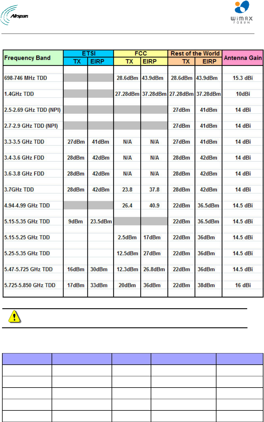
Maximum Output TX Power
Figure 1 - MicroMAX Maximum Output TX Power
Caution: Do not set maximum output TX power to higher than local regulations.
700MHz External Antennas
Table 1 - 700MHz External Antenna Types
Type Frequency range Gain Manufacturer Model number
V-Pol MCX 698-746 MHz 7.5 dBi Mars Antennas MA-WA70-AS8
Flat panel 698-746 MHz 10.5 dBi Mti Wireless Edge Ltd. MT-223003/N
Sector 698-746 MHz 12 ± 0.5 dBi Mti Wireless Edge Ltd. MT-223002/NV
Sector 698-746 MHz 13.5 dBi Mti Wireless Edge Ltd. MT-223006/NV
Yagi directional 698 - 746 MHz 15.3 dBi Trival antene AD-40/722-14
MicroMAX Hardware Installation User Guide
Page 14 Commercial in Confidence UWB-D00068 Rev J
1 About this Guide
This section discusses the purpose, intended audience, conventions, referenced documentation
and organization for this guide.
1.1 Purpose
This guide provides step-by-step instructions for setting up and installing the MicroMAX BSR.
The purpose of this User Guide is to provide step-by-step instructions for setting up and installing
the MicroMAX BSR. These procedures include:
¾ System Overview
¾ Installation Prerequisites
¾ Physical descriptions
¾ Mounting
¾ Cabling
¾ Connecting
¾ Lightning and Surge Protection
1.2 Intended Audience
This guide is intended for qualified and authorized technicians who are responsible for installing
the MicroMAX BSR.
1.3 Conventions
Icon Description
Checkpoint: Marks a point in the workflow where there may be an exit or
branch to some other procedure. At each Checkpoint the reason for an
exit or branch is given along with specific directions to locate the entry
point in the other procedure.
Reference: Gives a resource in the workflow that may be needed to
complete a procedure along with specific directions to use the resource.
Caution: Describes a possible risk and how to lessen or avoid the risk.
Advice: Provides a recommendation based on best practice.
Note: Provides useful information.
1.4 Referenced Documentation
For a description of the Web-based management tools for configuring and managing MicroMAX
BSR, see the following manual:
¾ MicroMAX Web-based Management User's Guide
¾ MicroMAX Overview

MicroMAX Hardware Installation User Guide
Page 15 Commercial in Confidence UWB-D00068 Rev J
2 System Overview
MicroMAX is a highly upgradeable Micro-cell base station, based on the Sequans System On a
Chip (SOC), with a pole/roof (wall) mounted radio system and antennae. This high performance
chip can support up to 28 + 28 MHz channels (full duplex) forms part of the AIRSPAN WIMAX
portfolio of WiMAX network infrastructure equipment. It is compatible with the Airspan EasyST
and ProST subscriber terminals and other manufacturer's CPEs that are fully WiMAX compliant.
The MicroMAX BSR is an outdoor radio that is mounted outside on a pole or wall. The BSR
provides a wireless link with subscribers and interfaces with the provider's backbone. The
MicroMAX BSR is available in two models. These models differ by antenna design (providing
integral flat-panel antennas, or an N-type port for attaching third-party external antennas).
MicroMAX BSR is available in numerous frequency bands, operating in FDD and TDD modes in
numerous channels see: MicroMAX Frequency Ranges.
The BSR connects to the indoor Ethernet switch by a CAT-5e cable, which carries the Ethernet
signal, and DC power. For a MicroMAX Base Station consisting of multiple BSRs, there are two
(2) options. The BSRs can be connected to individual Subscriber Data Adapters (SDA-4S) or to
Base Station Distribution Units (BSDU). For a Base Station consisting of a single BSR, the BSR
typically connects to a single Subscriber Data Adapter (SDA-4S or SDA-4SDC).
MicroMAX BSR provides a low cost, high-performance point-to multipoint packet-based
Broadband Wireless Access (BWA) solution. MicroMAX BSR Provides wireless connectivity
designed to deliver high-speed data, voice over IP (VoIP) and multimedia services to residential,
SOHO (Small Office/Home Office), and SME (Small to Medium Enterprises).
The MicroMAX is an encased outdoor radio providing access to the MicroMAX's communication
ports on its bottom panel. The MicroMAX's back panel provides holes for mounting.
MicroMAX BSR interfaces with the service provider's backbone through either:
¾ The SDA-4S Type II or the SDA-4SDC (referred henceforth as SDA-4S) integrated LAN
switches.
• SDA-4S Type II: integrated LAN switch, providing power and four 10/100BaseT ports
for interfacing with the subscriber’s network
• SDA-4SDC Type II: integrated LAN switch, providing power and four 10/100BaseT
interfaces and especially designed for implementation where available power supply
is DC (10 to 52 VDC), e.g. from a solar panel. This model provides regulated –48
VDC power to the BSR.
¾ Base Station Distribution Unit (BSDU) - provides an interface between multiple BSRs
and the service provider's backbone.
MicroMAX can be managed by an SNMP-based network management system (Netspan) using
standard and proprietary MIBs. In addition, external third-party management systems such as HP
OpenView can also manage the MicroMAX using these MIBs. Basic management can be
performed using any standard Web browser.
Note: For management refer to MicroMAX Web Management documentation.

MicroMAX Hardware Installation User Guide
Page 16 Commercial in Confidence UWB-D00068 Rev J
2.1 MicroMAX Frequency Ranges
The table below lists the frequency range of MicroMAX models currently available. This table will
grow as more models become available.
Table 2 - MicroMAX Frequency Ranges
Frequency Band Channel Bandwidth
698 – 746 MHz in TDD mode ¾ 2.5 MHz
¾ 5 MHz
¾ 10 MHz
1.42 - 1.52 GHz in TDD mode ¾ 1.5 MHz
¾ 1.75 MHz
¾ 2.5 MHz
¾ 5 MHz
2.5 – 2.69 GHz in TDD mode
NPI
¾ 2.5 MHz
¾ 5 MHz
¾ 10 MHz
2.7 – 2.9 GHz in TDD mode
NPI
¾ 3 MHz
¾ 6 MHz
¾ 10 MHz
3.3 - 3.5 GHz in TDD mode ¾ 1.75 MHz
¾ 2.75 MHz
¾ 3 MHz
¾ 3.5 MHz
¾ 5 MHz
3.4 - 3.5 GHz in FDD mode/ 50MHz ¾ 1.75 MHz
¾ 3.5 MHz
¾ 5 MHz *
3.4 - 3.6 GHz in FDD mode
(Lo, Hi)
¾ 1.75 MHz
¾ 3.5 MHz
3.4 - 3.6 GHz in TDD mode ¾ 1.75 MHz
¾ 3.5 MHz
¾ 5 MHz
3.6 - 3.8 GHz in FDD mode
(Lo, Hi)
¾ 1.75 MHz
¾ 3.5 MHz
3.6 - 3.8 GHz in TDD mode ¾ 1.75 MHz
¾ 3.5 MHz
¾ 5 MHz
¾ 7 MHz

MicroMAX Hardware Installation User Guide
Page 17 Commercial in Confidence UWB-D00068 Rev J
Frequency Band Channel Bandwidth
4.9 - 5.0 GHz in TDD mode ¾ 2.5 MHz
¾ 5 MHz
¾ 10 MHz
5.15 - 5.35 GHz in TDD mode ¾ 2.5 MHz
¾ 5 MHz
¾ 10 MHz
5.47 - 5.725 GHz in TDD mode ¾ 2.5 MHz
¾ 5 MHz
¾ 10 MHz
5.725 - 5.875 GHz in TDD mode ¾ 2.5 MHz
¾ 5 MHz
¾ 10 MHz
5.85 - 5.95 GHz in TDD mode ¾ 2.5 MHz
¾ 5 MHz
¾ 10 MHz
* As long as the central channel is an even number
2.2 System Components
¾ Outdoor - Unit(s):
• MicroMAX Base Station Radio(s) (BSR)
• Global Positioning System (GPS)
¾ Indoor:
• SDA-4S Type II: small low cost IDU with built in LAN switch
• SDA-4SDC Type II: small low cost DC IDU with built in LAN Switch
• GPSD: optional Global Positioning System Distribution unit (for up to 4 BSRs)
• BSDU: optional Ethernet switch for implementing Base Stations consisting of multiple
BSRs
¾ IDU/ODU connectivity:
• CAT-5e cable 24 gauge or better (22 gauge recommended) for connecting to BSR
(SFTP - Shielded Foiled Twisted Pair - recommended)
• Fast Ethernet: 4 pins
• VDC power: BSR FDD/TDD requires 2 pins
• IDU/ODU length for BSR FDD: up to 100 meters
¾ Minimum configuration:
• SDA-4S and a single BSR
¾ Larger configurations:
• N*SDA-4Ss and N*BSRs

MicroMAX Hardware Installation User Guide
Page 18 Commercial in Confidence UWB-D00068 Rev J
• N*BSRs and BSDU (up to 8 BSRs per unit)
¾ Optional AC/DC power converter - in the event -48 VDC is not available at BS site
2.3 Customer Benefits
The MicroMAX BSR offers the following customer benefits:
¾ Based on the latest wireless technology WiMAX IEEE 802.16 2004 standard
¾ SOC engine for best cost/performance
• Based on Sequans "System On a Chip" (SOC)
o high performance chip
o high growth potential
2.4 Architecture
The MicroMAX system consists of the following component designs:
¾ Integrated Antenna Design
• Encased MicroMAX BSR outdoor unit with integrated antenna
• SDA-4S Type II or SDA-4SDC Type II indoor unit
• GPSD (optional for up to 4 BSRs)
• BSDU (optional for multiple BSRs)
• GPS antenna utilized with BSDU
• External AC/DC power converter (optional)
¾ External Antenna Design
• Encased MicroMAX BSR outdoor unit
• SDA-4S Type II or SDA-4SDC Type II indoor unit
• BSDU (optional for multiple BSRs)
• GPS antenna utilized with BSDU or GPSD unit
• Third-party external antenna (optional deployment)
¾ External AC/DC power converter (optional)
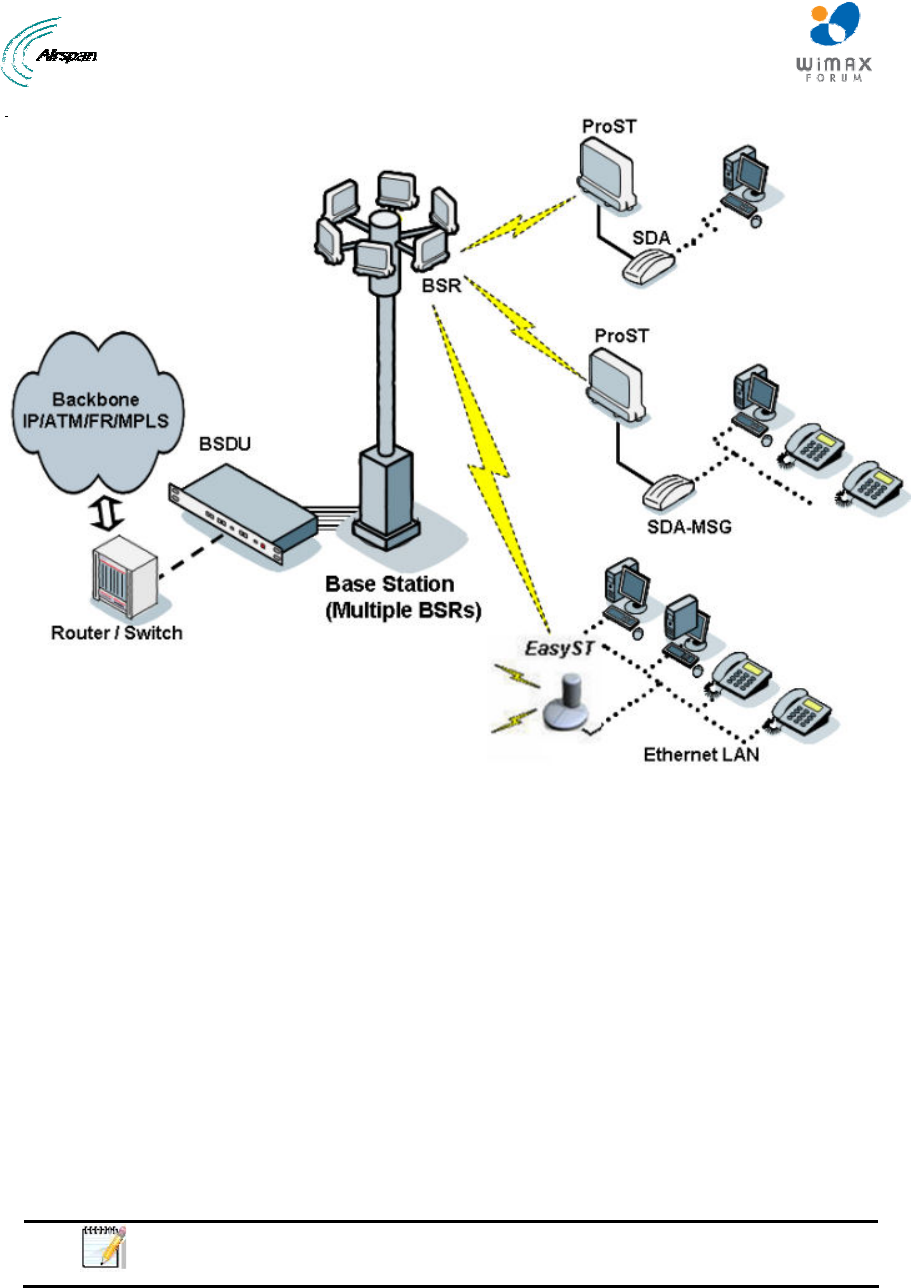
The figures below displays a typical setup (using BSDU) of the MicroMAX(s) mounted outdoors
on a pole (with an integrated antenna).
MicroMAX Hardware Installation User Guide
Page 19 Commercial in Confidence UWB-D00068 Rev J
Figure 2 - Typical Setup
2.5 Power
¾ The SDA-4S is a switch providing the MicroMAX BSR with -48 VDC power supply, and
10/100BaseT interface with the subscriber's PCs/network.
¾ The BSDU is also responsible for providing BSRs with -48 VDC power supply and for
synchronizing BSDUs, BSRs and Base Stations (when a GPS is implemented).
¾ An external AC/DC power converter (optional) is available in the event -48 VDC is not
available at BS site. Contact your Airspan supplier.
2.6 Models
The MicroMAX is available in the following basic physical designs:
¾ MicroMAX with a built-in (integral), internal antenna.
¾ MicroMAX with an N-type type RF connector for connecting an optional third-party
external antenna.
Note: A MicroMAX with an N-type port for attaching a third-party external
antenna does not provide a built-in antenna.

MicroMAX Hardware Installation User Guide
Page 20 Commercial in Confidence UWB-D00068 Rev J
3 Installation Prerequisites
Before installing your MicroMAX, review:
¾ Package Contents
¾ Required tools
¾ Radio Site planning
3.1 Package Contents
Examine the AIRSPAN WIMAX shipping container. If you notice any damage, or missing items as
listed in the Packing List, immediately notify the carrier that delivered the unit and contact a
Airspan representative.
The MicroMAX kit should contain the following items:
¾ MicroMAX Base Station radio
¾ DB15-to-RJ45 adapter for plugging into the BSR's 15-pin D-type port
¾ Pole-mounting kit:
o 2 x M10 hex head screws
o 2 x M10 flat washers
o 2 x M10 spring lock washers
o 2 x M10 hex nuts
• Mounting bracket
o 2 x M6 hex head screws
o 2 x M6 spring lock washers
• Clamping bracket
o 2 x M8 'U'- bolts
o 4 x M8 hex nuts
o 4 x M8 plain washers
o 4 x M8 spring lock washers
The GPSD (optional) kit should contain the following items:
¾ GPSD (AC or DC)
¾ Power cable – for AC
¾ GPS antenna
¾ 4 “Y” cables
The GPS kit should contain the following items:
¾ GPS Smart Antenna RS422
¾ Conn DB15PM AMP - for discrete wires IDC
¾ Connector, Circular (Deutsch IMC26-2212X) - Industrial Micro 12P F
¾ Cable 4x2422# (CAT-5e) - 10 meters
¾ 8x Contact sockets (for Deutsch 6862-20122278) - Circular Micro connectors
¾ Boot shrink w/ glue (Raychem) - heat shrink
¾ Plastic Hood 15-Pin - D-Type sub-connector

MicroMAX Hardware Installation User Guide
Page 21 Commercial in Confidence UWB-D00068 Rev J
Note: The standard MicroMAX kit does not include wall-mounting
accessories. For pricing and ordering of wall-mounting accessories, please
contact your nearest Airspan dealer.
3.2 Required Tools
The following tools are required to install the MicroMAX unit:
¾ Torque wrench for N-type connectors (only relevant when implementing external
antenna)
¾ Cable stripping tool
¾ 10-mm, 13-mm, and 17-mm A/F open ended spanners
3.3 Radio Site Planning
Proper site selection and planning before installing your MicroMAX will ensure a successful
deployment of your AIRSPAN WIMAX system. A summary of the main site planning
considerations is provided below:
¾ Minimum obstructions (e.g. buildings) in the radio path between base station and the
subscriber terminals.
¾ Mount radio as high as possible to avoid obstructions in the wireless path.
¾ Check possibility of future obstructions such as plans to erect buildings and trees that
may grow tall enough to obstruct the wireless path.
¾ Align radio for maximizing received signal strength (RSS).
¾ Consider nearby sources of interference that could degrade performance of radio.
¾ Mount radio as far from sources of interference as possible.
¾ Ensure base station and subscriber terminals (i.e ProST/EasyST) are within maximum
coverage range of reception.
¾ Maximum standard CAT-5e cable length connecting the MicroMAX to the indoor SDA-4S
or BSDU is 100 meters.
¾ Ensure that you have sufficient wiring conduit and cable ties to channel and protect the
CAT-5e cable connecting the outdoor MicroMAX to the indoor SDA-4S.
3.3.1 Radio Antenna Alignment
ProST
Once the subscriber unit (i.e. ProST) is installed and aimed in the general direction of the BSR, it
is recommended to measure the received signal strength (RSS) to determine the signal strength
received from the BSR, and to precisely align the ProST for maximum signal strength.
You need to orientate (up/down, left/right) the ProST until the maximum RSSI levels are achieved,
and then secure the ProST.
EasyST
Once the subscriber unit (i.e. EasyST) is installed and aimed in the general direction of the BSR,
simply move the EasyST to the position that gives optimal reception.
MicroMAX Hardware Installation User Guide
Page 22 Commercial in Confidence UWB-D00068 Rev J
4 Physical Description
This section provides a description of the components of the MicroMAX installation:
¾ MicroMAX (outdoor unit)
¾ SDA-4S Type II (indoor unit)
¾ SDA-4SDC Type II (indoor DC unit)
4.1 MicroMAX BSR
The BSR is an encased outdoor radio providing access to communication ports on its bottom
panel. The BSR's back panel provides holes for mounting.
4.1.1 Physical Dimensions
The table below lists the physical dimensions of the BSR.
Table 3 - BSR Dimensions
Parameter Value Comment
Height 400 mm (15.74 inches)
Width 317 mm (12.48 inches)
Depth 65.5 mm (2.58 inches)
Weight 3.8 kg
The physical dimensions exclude the mounting kit.
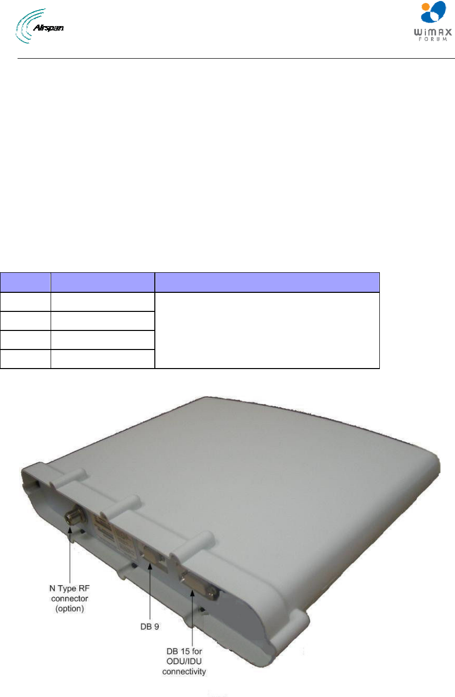
The figure below illustrates the MicroMAX's physical dimensions.
Figure 3 - BSR ports
MicroMAX Hardware Installation User Guide
Page 23 Commercial in Confidence UWB-D00068 Rev J
Note: BSR models that use third-party external antennas provide an N-type
receptacle for attaching an external antenna.
4.1.2 Ports
The table below defines the different ports on the bottom panel.
Table 4 - BSR ports
Port interfaces Description
DB 15 IDU/ODU interface:
¾ Fast Ethernet from/to SDA-4S or SDA-4SDC
Type II and BSDU
¾ Power from SDA-4S Type II or SDA-4SDC
Type II and BSDU
¾ TDD Tx/Rx sync from BSDU
DB 9 Engineering applicability (Technical Service only)
N Type RF connector - relevant
when implementing external antenna
External antenna connection
Note: Some previous models (still in use) have an RJ45 port with cover
which has been discontinued as of December 2006.
MicroMAX is powered from the indoor integrated LAN switch:
Note: The SDA-4S Type II and the SDA-4SDC are physically (externally) the
same other than the power socket.
MicroMAX Hardware Installation User Guide
Page 24 Commercial in Confidence UWB-D00068 Rev J
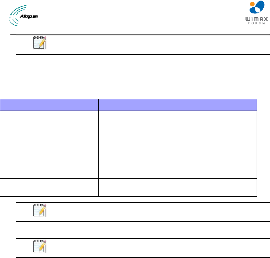
4.2 SDA-4S Type II
The SDA-4S Type II indoor unit (hereafter referred to as SDA-4S) is an integrated LAN switch,
providing power and four 10/100BaseT ports for interfacing with the subscriber’s network. The
unit is displayed in the figure below.
Figure 4 - SDA-4S Type II
This subsection provides the following SDA-4S physical descriptions:
¾ Dimensions
¾ Ports
¾ LEDs
4.2.1 Physical Dimensions
The SDA-4S physical dimensions are described in the table below:
Table 5 - SDA-4S dimensions
Parameter Value
Dimensions Height - 200mm (7.87 inches)
Width - 150mm (5.9 inches)
Depth - 40mm (1.57 inches)
Weight 0.53 Kg
MicroMAX Hardware Installation User Guide
Page 25 Commercial in Confidence UWB-D00068 Rev J
4.2.2 Ports
The SDA-4S adapter provides ports on the front panel, which are described in the table below:
Table 6 - SDA-4S ports
Port Interface
4 x 8-pin RJ-
45
10/100BaseT with subscriber's network (supports Auto Negotiation and
MDI/MDI-X automatic crossover, allowing connection of straight-through or
crossover cables)
15-pin D-type
(female)
10/100BaseT with BSR
AC power
socket
Subscriber's power outlet (110-240 VAC, 1A, 50/60 Hz, 50W)
Note: The ports of the SDA-4S models support Auto Negotiation, allowing
automatic configuration for the highest possible speed link (10BaseT or
100BaseT), and Full Duplex or Half Duplex mode. In other words, the speed
of the connected device (e.g. PC) determines the speed at which packets are
transmitted through the specific SDA-4S port. In addition, the SDA-4S ports
support MDI/MDI-X automatic crossover, allowing connection to straight-
through or crossover cables.
4.2.3 LEDs
The LEDs description is the same as for the SDA-4SDC below.
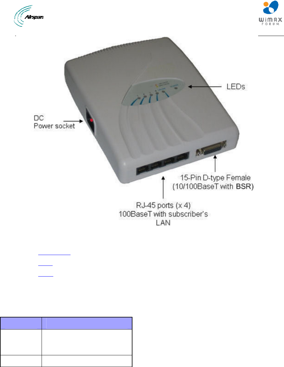
4.3 SDA-4SDC Type II
The SDA-4SDC Type II indoor unit is an integrated LAN switch, providing power and four
10/100BaseT ports for interfacing with the subscriber’s network and especially designed for
implementation where available power supply is DC. This model provides regulated –48 VDC
power. The unit is displayed in the figure below.
MicroMAX Hardware Installation User Guide
Page 26 Commercial in Confidence UWB-D00068 Rev J
Figure 5 - SDA-4SDC Type II
This subsection provides the following SDA-4SDC physical descriptions:
¾ Dimensions
¾ Ports
¾ LEDs
4.3.1 Physical Dimensions
The SDA-4SDC physical dimensions are described in the table below:
Table 7 - SDA-4SDC dimensions
Parameter Value
Dimensions Height - 200mm (7.87 inches)
Width - 150mm (5.9 inches)
Depth - 40mm (1.57 inches)
Weight 0.53 Kg
MicroMAX Hardware Installation User Guide
Page 27 Commercial in Confidence UWB-D00068 Rev J
4.3.2 Ports
The SDA-4SDC adapter provides ports on the front panel, which are described in the table below:
Table 8 - SDA-4SDC ports
Port Interface
4 x 8-pin RJ-
45
10/100BaseT with subscriber's network (supports Auto Negotiation and
MDI/MDI-X automatic crossover, allowing connection of straight-through or
crossover cables)
15-pin D-type
(female)
10/100BaseT with BSR
DC power
socket
DC power outlet (10-52 VDC, 24W)
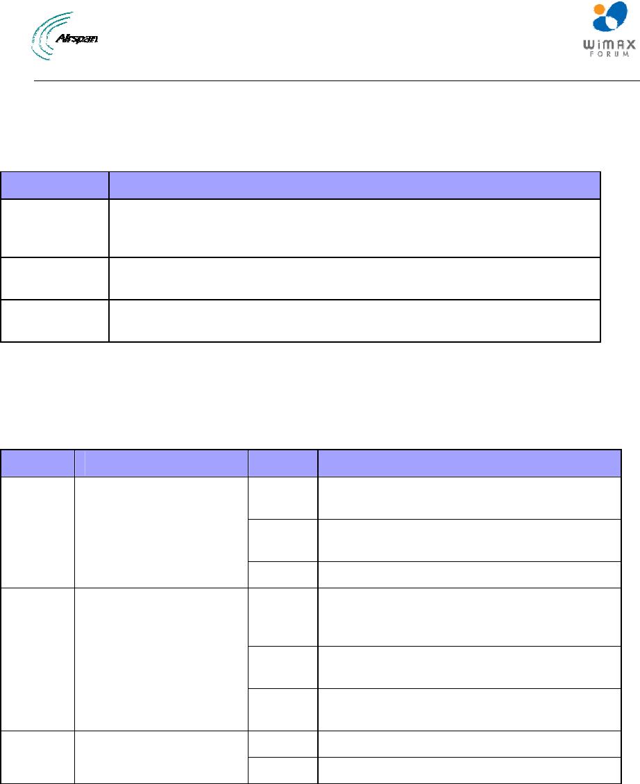
4.3.3 LEDs
The SDA-4S (all types) adapter provides LED indicators on the top panel, which are described in
the table below:
Table 9 - SDA-4S LEDs
LED Color Status Description
On Physical link (10BaseT or 100BaseT)
between SDA-4S adapter and BSR
Blinking Traffic currently flowing between SDA-4S and
BSR
UPLINK Yellow (100BaseT) or
Orange (10BaseT)
Off No link between SDA-4S and BSR
On Physical link (10BaseT or 100BaseT)
between SDA-4S and subscriber's Ethernet
network
Blinking Traffic currently flowing between SDA-4S and
subscriber's Ethernet network
1, 2, 3,
4 Yellow (100BaseT) or
Orange (10BaseT)
Off No link between SDA-4S and subscriber's
Ethernet network
On Power received by SDA-4S
POWER Green
Off No power received by SDA-4S
The figure below displays the LEDs which are located on the top panel of the SDA-4S adapter:
MicroMAX Hardware Installation User Guide
Page 28 Commercial in Confidence UWB-D00068 Rev J
Figure 6 - SDA-4S top panel

MicroMAX Hardware Installation User Guide
Page 29 Commercial in Confidence UWB-D00068 Rev J
5 BSDU Description
This section provides a description of the Base Station Distribution Unit (BSDU).
The BSDU is connected to the BSRs by standard CAT-5e cables. Each BSDU can service a
maximum of 8 BSRs. In addition, up to two BSDUs can be daisy-chained at a Base Station,
supporting up to 16 BSRs. Therefore, a Base Station at maximum configuration can serve up to
8192 subscribers (i.e. 16 BSRs multiplied by 512 subscribers).
The BSDU provides a 15-pin D-type port for interfacing with the BSRs, for convenience, a DB15-
to-RJ45 adapter is supplied for attaching to the 15-pin D-type port to allow the use of RJ-45
connectors for outdoor-to-indoor CAT-5e cable connectivity.
The AIRSPAN WIMAX Base Station Distribution Unit (BSDU) provides an interface between
multiple MicroMAX (BSRs) and the service provider’s backbone. The BSDU provides the
following functionalities:
¾ Data switching and aggregation:
• Data switching between up to eight MicroMAX BSRs over 10/100 BaseT interface.
• Aggregate the MicroMAX BSRs data via two 1000BaseT Ethernet (GE) ports towards
the backhaul/backbone or to cascade to another BSDU.
¾ Synchronization:
• Tx / Rx TDD synchronization for multiple MicroMAX BSRs per BSDU and between
connected BSDUs.
• GPS for TDD Tx / Rx synchronization of different BS sites.
¾ Power distribution
• Provides DC power from a single -48 VDC source to eight MicroMAX BSRs.
• AC/DC power converter (optional) - in the event -48 VDC is not available at BS site.
Note: The unit should be powered by -48Vdc (40-54Vdc), 4.5A from safety
approved power supply that its output is SELV and is separated from mains
by minimum double/reinforced insulation.
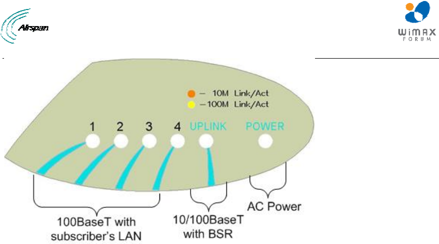
5.1 Physical Dimensions
The table below lists the physical dimensions of the BSDU.
Table 10 - BSDU dimensions
Parameter Value Comment
Height 43.2 mm (1.7 inches)
Width 482.6 mm (19 inches)
Depth 228.6 mm (9 inches)
Weight 2.9 kg
The physical dimensions exclude the bracket flanges for mounting.
The figure below illustrates the BSDU's physical dimensions.
MicroMAX Hardware Installation User Guide
Page 30 Commercial in Confidence UWB-D00068 Rev J
Figure 7 - BSDU front
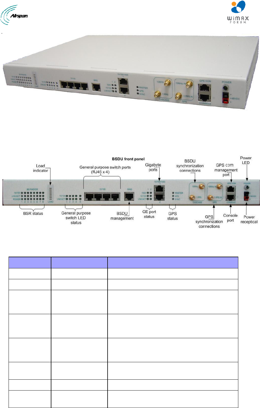
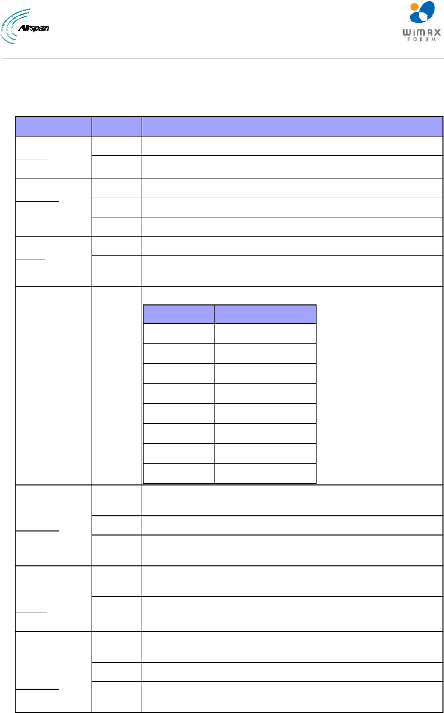
5.2 Ports
The BSDU provides various hardware interfaces on its front and rear panel as described in the
tables and figures below.
Figure 8 - BSDU Front Panel
The following table lists the front panel hardware interfaces (refer to the front panel figure):
Table 11 - Front Panel Interfaces
Port Label Interface
8-pin RJ-45 (4) 10/100 4 x 10/100 BaseT general purpose switch
8-pin RJ-45 MNG 10/100 BaseT for out-of-band management
8-pin RJ-45 (2) 10/100/1000 1 / 2 1 - Interface with provider’s backbone
2 – Daisy-chained BSDUs, interface with another
BSDU for cascading
SMA (2) GPS
10MHz IN & 1PPS IN
Interface with GPS for global clock synchronization
by means of 2 signals: 10 MHz and 1 PPS
For future use
SMA (2) CASCADE
10MHz & 1PPS
Interfaces with a daisy-chained BSDU for
cascading the 2 GPS signals
For future use
8-pin RJ-45 GPS COM Interfaces with the GPS serial port for getting
status and alarms
8-pin RJ-45 CONSOLE BSDU serial port for initial configuration
Power
Receptacle
-48VDC -48 VDC supply from external feeding source
MicroMAX Hardware Installation User Guide
Page 31 Commercial in Confidence UWB-D00068 Rev J
The BSDU provides LEDs for indicating the status of various operations. The LEDs are located on
the front panel. The LEDs colors are green with 3 optional states: Off, On and Flashing. The
following table details the LEDs functionality:
Table 12 - BSDU LEDS description
LED Status Description
On BSR is connected when the link is On (100 Base-T)
BSR Status
10/100
(1–8) Off BSR is connected when the link is On (10 Base-T)
On Physical link exists between BSDU and BSR
Flashing Ethernet activity detected on BSR port
BSR Status
LNK/ACT
(1–8)
Off No physical link exists between BSDU and BSR
On Power supplied to BSDU’s BSR port
BSR Status
Power
(1–8) Off BSDU’s BSR port is disabled by software, or port failure has
occurred
Load Indicator 8 levels of
On
The Traffic Load Bar indicates 8 traffic levels via 8 LEDs:
No. of LEDs Utilization
1 0.4%
2 0.8%
3 1.6%
4 3.2%
5 6.4%
6 12.8%
7 25%
8 Over than 50%
On Viable physical link between the 10/100 Base-T port and the
external device to which this port connects
Flashing Ethernet activity detected on 10/100 Base-T port
General
Purpose
Switch
LNK/ACT
(1–5) Off No physical link between 10/100 Base-T port and external device
to which this port connects
On The link between the general purpose switch port and the external
device is synchronized with a rate of 100 Base-T
General
Purpose
Switch
10/100
(1–5)
Off The link between the general purpose switch port and the external
device is synchronized with a rate of 10 Base-T
On Viable physical link between the 10/100/1000 Base-T port towards
the backhaul or the daizy-chained BSDU
Flashing Ethernet activity detected on 10/100 Base-T port
GE Ports
Status
Backhaul /
Cascade
LNK/ACT
(1–2) Off No physical link between the 10/100/1000 Base-T port towards the
backhaul or the daizy-chained BSDU
MicroMAX Hardware Installation User Guide
Page 32 Commercial in Confidence UWB-D00068 Rev J
LED Status Description
On The link between the GE port and the backhaul or the daizy-
chained BSDU is synchronized with a rate of 100 Base-T
GE Ports
Status
Backhaul /
Cascade
10/100
(1–2)
Off The link between the GE port and the backhaul or the daizy-
chained BSDU is synchronized with a rate of 10 Base-T
On The link between the GE port and the backhaul or the daizy-
chained BSDU is synchronized with a rate of 1000 Base-T
GE Ports
Status
Backhaul /
Cascade
1000
(1–2)
Off The link between the GE port and the backhaul or the daizy-
chained BSDU is not synchronized with a rate of 1000 Base-T
On Master provides the GPS clock source in case of BSDUs
cascading
GPS Status
Master
Off Slave gets the GPS clock from the Master BSDU in case of
BSDUs cascading
On GPS is connected
GPS Status
GPS Off No GPS is connected
Flashing When the GPS sync pulse is received
GPS Status
SYNC Off No GPS sync pulse
Power On Indicates whether the BSDU gets the -48 VDC from external
source
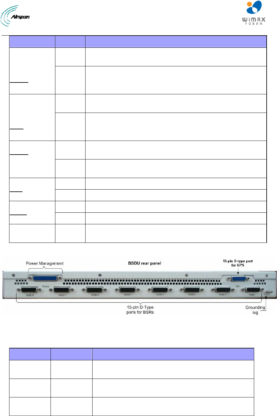
Figure 9 - BSDU Rear Panel
The following table lists the rear panel hardware interfaces (refer to the rear panel figure):
Table 13 - Rear panel Interfaces
Port Label Interface
15-pin D-type
female (8)
BSR 1 – BSR
8
Provides 10/100 Base-T (Ethernet),synchronization and 48
VDC power feed interfaces with BSRs
25-pin D-type
female
External
Power Supply
For external Power Supply (AC/DC) management
15-pin D-type
female (1)
GPS Global Positioning System (GPS)-based synchronization
MicroMAX Hardware Installation User Guide
Page 33 Commercial in Confidence UWB-D00068 Rev J
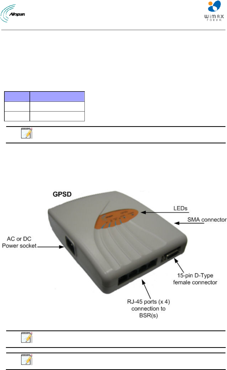
6 GPSD Description
This section provides a description of the Global Positioning System Distribution unit (GPSD)
(Optional). The GPSD distributes GPS synchronization to up to 4 BSRs.
The GPSD unit is a, self-contained GPS Distribution unit and is available in 2 models, either in 10
to 52 VDC or in 110-240 VAC, 1A, 50/60 Hz, 50W. The GPSD is an optional unit that connects up
to four (4) SDA-4S (or SDA-4SDCs).
Table 14 - GPSD Voltage & Currency Ratings
Models Ratings
AC 110-240 VAC, 0.25A
DC 10-52 VDC, 1A
Note: The DC unit should be powered by a limited power source of up to 3A.
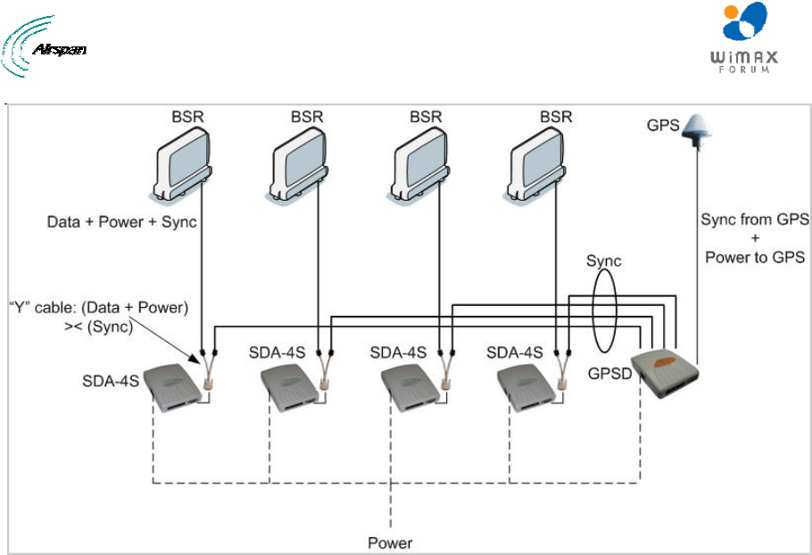
The GPSD incorporates two (2) connections for different GPS connections. There is an SMA
connection for use with the included external GPS antenna which works in conjunction with the
internal GPS module. The internal GPS synchronizes multiple (up to 4) Base Stations, ensuring
that the entire network operates with the same clock based on a universal satellite clock signal.
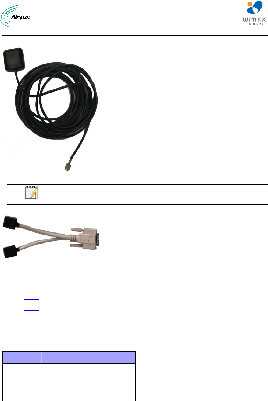
There is also a 15-PIN D-Type connection for use with a third-party GPS antenna. The GPSD,
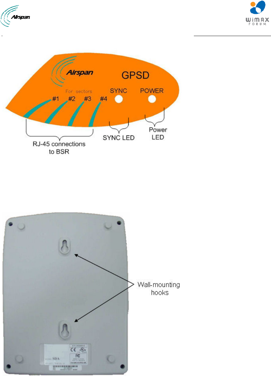
external antenna and “Y” cable are displayed in the figures below:
Figure 10 – GPSD
Note: Service personnel must install the AC unit connected to a properly
grounded outlet.
Note: To reduce the risk of fire only no.26 AWG or larger telecommunication
line cord should be used.
MicroMAX Hardware Installation User Guide
Page 34 Commercial in Confidence UWB-D00068 Rev J
Figure 11 - External antenna (included)
Note: The supplied external antenna is limited to 5 meters long.
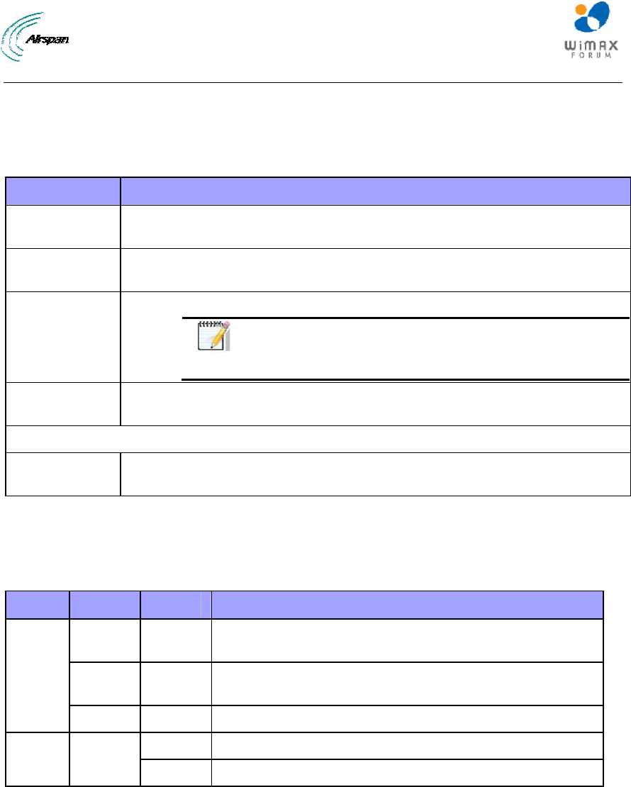
Figure 12 - "Y" cable (4 included)
This section provides the following GPSD physical descriptions:
¾ Dimensions
¾ Ports
¾ LEDs
6.1 Physical Dimensions
The GPSD physical dimensions are described in the table below:
Table 15 - GPSD dimensions
Parameter Value
Dimensions Height - 200mm (7.87 inches)
Width - 150mm (5.9 inches)
Depth - 40mm (1.57 inches)
Weight 0.53 Kg
MicroMAX Hardware Installation User Guide
Page 35 Commercial in Confidence UWB-D00068 Rev J
6.2 Ports
The GPSD adapter provides ports on the front panel, which are described in the table below:
Table 16 - GPSD ports
Port Interface
4 x 8-pin RJ-
45
10/100BaseT with subscriber's BSRs (up to 4).
15-pin D-type
(female)
For connection to external GPS antenna for SYNC from the GPS and power
to the GPS.
4 x “Y” cables Split – supplies power & data from SDA-4S(DC) and SYNC from GPSD.
Note: Cables are clearly labeled “MicroMAX” and
“GPSD”. The RJ45 Jacks are clearly labeled
“MicroMAX” and “GPSD”.
AC power
socket
Subscriber's power outlet (110-240 VAC, 1A, 50/60 Hz, 50W)
OR
DC power
socket
DC power outlet (10-52 VDC, 24W)
6.3 LEDs
The GPSD provides LED indicators on the top panel, which are described in the table below:
Table 17 - GPSD LED description
LED Color Status Description
Orange On When the board is in reset (normally will blink for 200ms
when power ON - Power on reset).
Green Blinking When receiving 1PPS from the GPS blinks 1 second for
300-400 ms
SYNC
Off No PPS was received from the GPS
On Appropriate power is being fed to the unit
Power Green
Off No power
The figure below displays the LEDs which are located on the top panel of the GPSD:
MicroMAX Hardware Installation User Guide
Page 36 Commercial in Confidence UWB-D00068 Rev J
Figure 13 - GPSD top panel
6.4 Mounting the GPSD
The GPSD is mounted vertically on a wall in the communication center within connection distance
of the SDA-4S(s) it services. Wall mounting is made possible by the existence of two mounting
hooks molded into the GPSD's bottom panel, as displayed in the figure below.
Figure 14 - Wall mount
MicroMAX Hardware Installation User Guide
Page 37 Commercial in Confidence UWB-D00068 Rev J
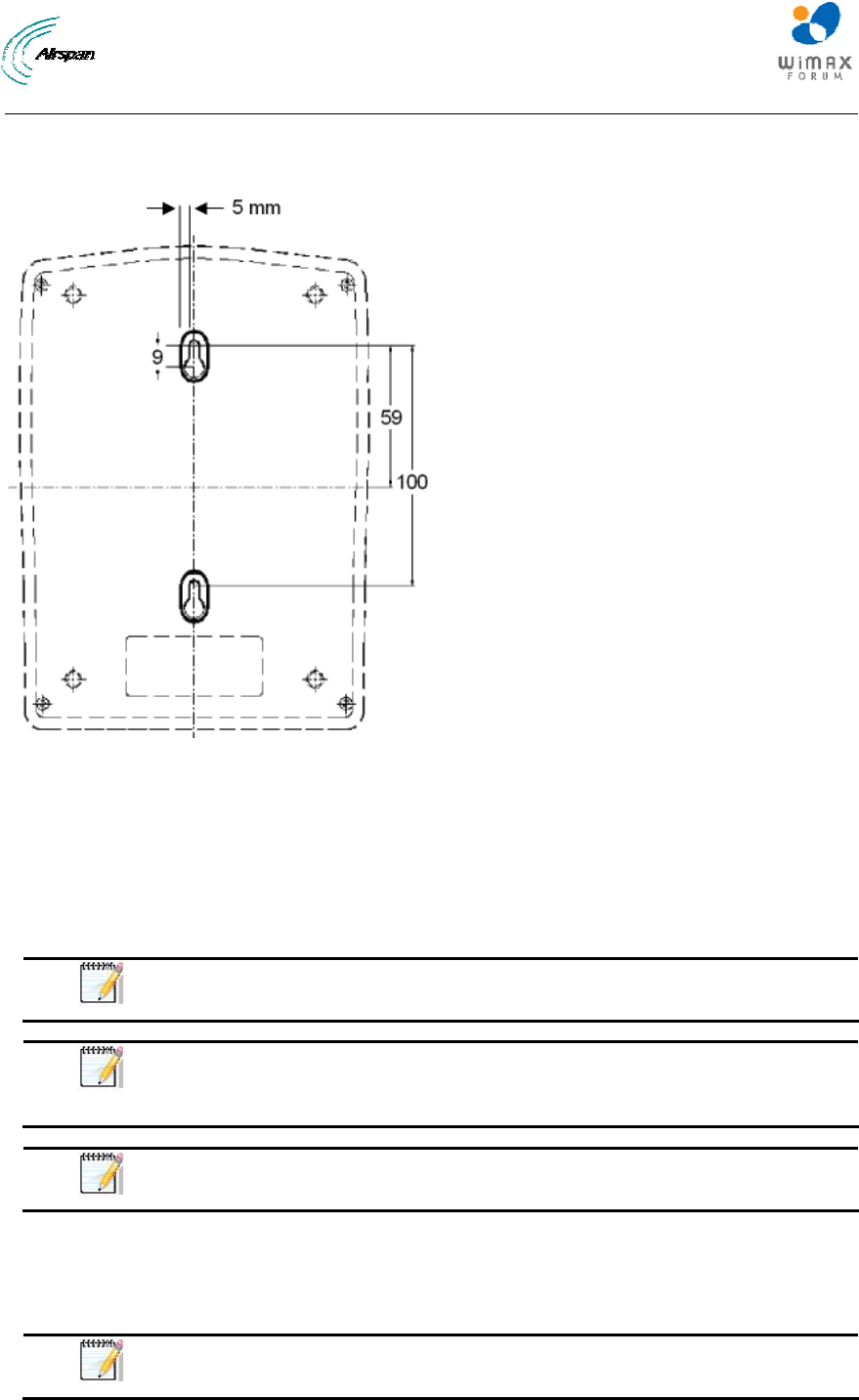
To wall mount the GPSD:
On the wall, mark the position of the two mounting hooks. The dimensions of the wall-mounting
hooks are displayed in the template below.
Figure 15 - mounting template
1. Drill holes for each hole that you marked in the step above.
2. Insert wall anchors (supplied) into each of the drilled holes.
3. Insert the 9-inch screws (supplied) into the wall anchors. Ensure at least 2 mm of the screw
is exposed to allow insertion into the GPSD mounting holes.
4. Hold the GPSD with both hands, and align the entrance to the two mounting hooks with the
screws. Slide the screws into the mounting hooks, by lowering the GPSD onto the screws.
Note: For safety, both mounting hooks must be utilized when mounting the
unit.
Note: The GPSD is supplied with a 1-metre AC power lead assembly.
Therefore, ensure the unit is mounted within reachable distance to the
customer's mains power outlet.
Note: The maximum cable run between GPSD and MicroMAX is 100 meters.
Therefore, ensure the unit is mounted within reachable distance.
6.5 GPSD Architecture
The figures below display a typical setup, using the GPSD, multiple BSR(s), multiple SDA-4S or
SDA-4SDC, “y” cable and the GPS antenna.
Note: Alternately you can use the supplied external antenna which is limited
to 5 meters long.
MicroMAX Hardware Installation User Guide
Page 38 Commercial in Confidence UWB-D00068 Rev J
MicroMAX Hardware Installation User Guide
Page 39 Commercial in Confidence UWB-D00068 Rev J
7 GPS Description
This section provides a description of the Global Positioning System (GPS).
Note: Even if there is a single isolated BS with multiple sectors the GPS is
required.
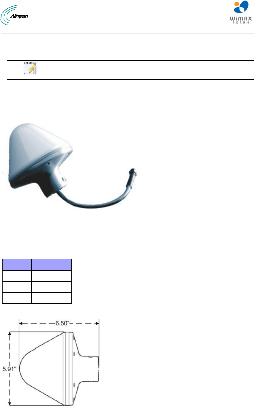
The third-party GPS antenna is a rugged, self-contained GPS receiver and antenna that receives
a universal GPS satellite clock signal. The GPS connects to the BSDU. The GPS synchronizes
(based on frequency hopping) multiple Base Stations, ensuring that the entire Airspan WiMAX
network operates with the same clock based on a universal satellite clock signal. This is crucial in
eliminating radio frequency ghosting effects.
Figure 16 - GPS antenna
7.1 Physical Dimensions
The GPS physical dimensions are described in the following table.
Table 18 - GPS dimensions
Parameter Value
Diameter 5.91" (15.0 cm)
Height 6.5" (16.5 cm)
Weight 684g (1.51 lb)
The figure below illustrates the GPS's physical dimensions.
Figure 17 - GPS dimensions
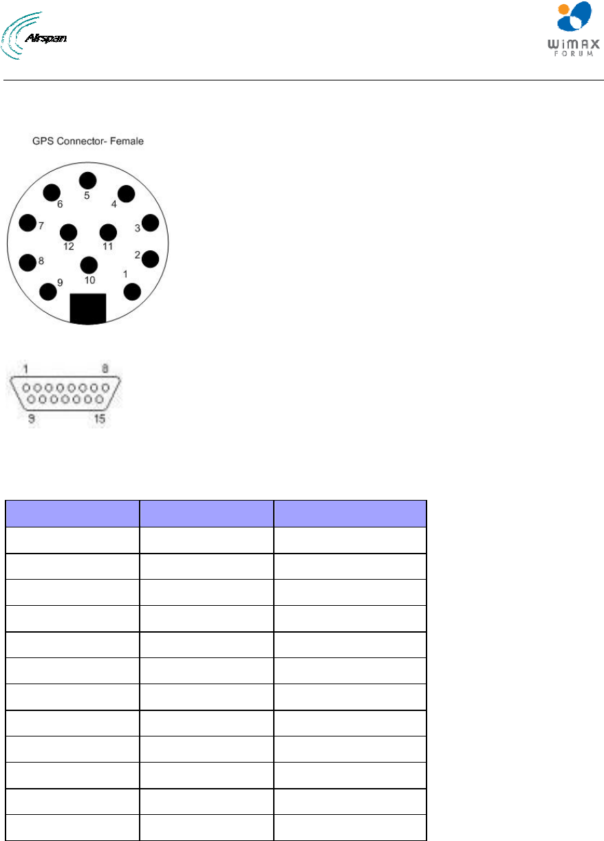
MicroMAX Hardware Installation User Guide
Page 40 Commercial in Confidence UWB-D00068 Rev J
7.2 Ports
The GPS provides 12-pin male contacts for connecting a cable between it and the BSDU.
Figure 18 - GPS pinouts
Figure 19 - Db-15
The connectors’ pinouts are described in the following table; connections should be as defined.
Table 19 - GPS Pinouts
Db-15 Connector GPS connector Description (GPS side)
13 1 Power +
6 2 Receive -
5 3 Receive +
4 4 Transmit –
3 5 Transmit +
-- 6(NC)
-- 7(NC)
-- 8(NC)
12 9 Power -
10(NC)
7 11 PPS+
8 12 PPS-
7.3 Crimping GPS Cable
The third-party Global Positioning System antenna (GPS) connects to the BSDU's 15-pin D-type
port. Therefore, the cable from the GPS needs to be crimped to a 15-pin D-type male connector.
Airspan recommends using the Daniels AFM8 (M22520/2-01) crimping tool for crimping the GPS
cable to 15-pin D-type connectors.
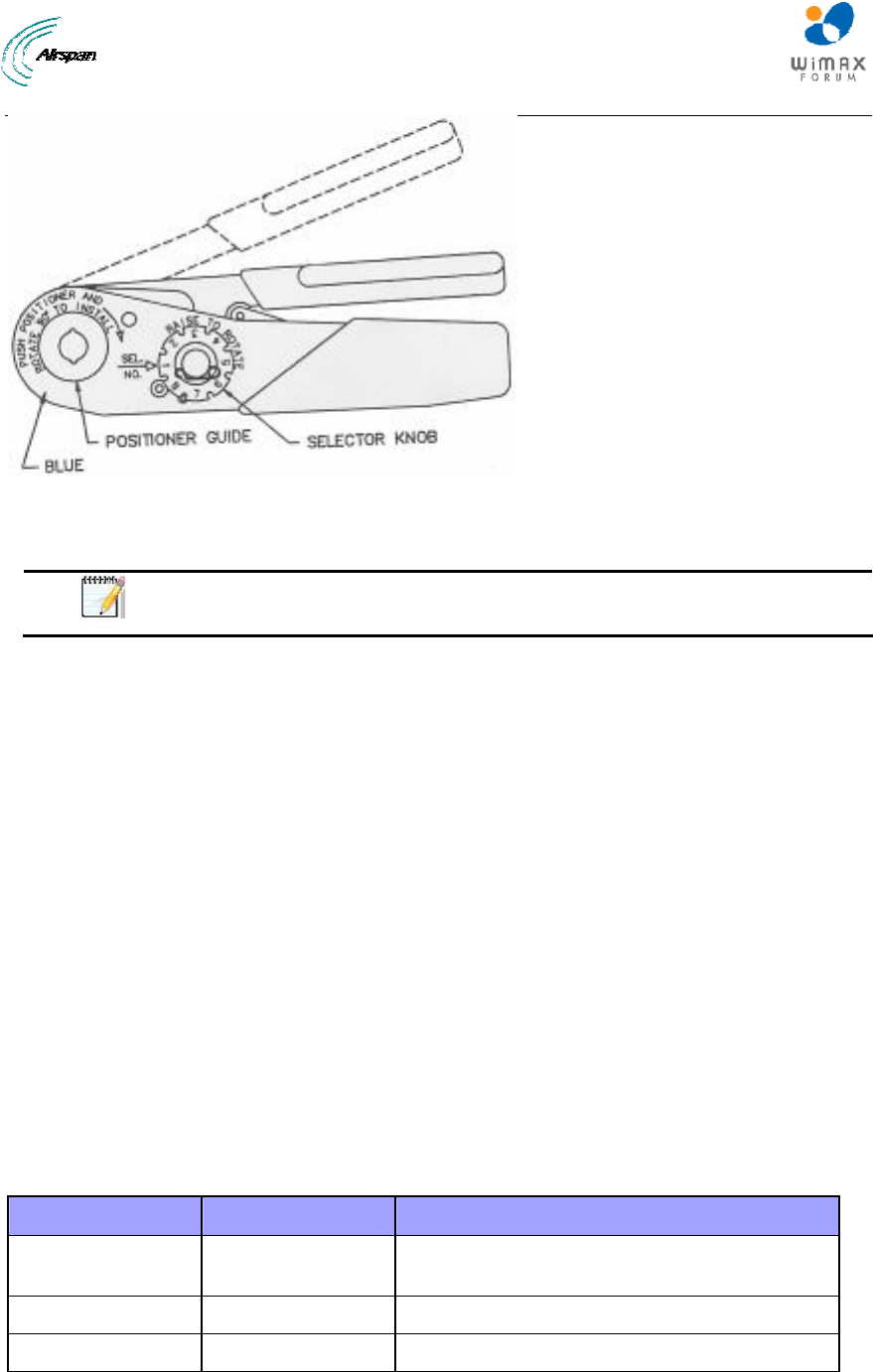
MicroMAX Hardware Installation User Guide
Page 41 Commercial in Confidence UWB-D00068 Rev J
Figure 20 - Crimping tool (Daniels AFM8)
Once you have housed the stripped cable, you can now crimp the cable to 15-pin D-type
connector.
Note: The crimper cannot be opened without completing the cycle.
To crimp the GPS's cable:
1. Ensure that the crimper is in the open position.
2. Remove safety clip from positioner guide.
3. Select the Positioner for contact to be crimped.
4. Insert the Positioner into the positioner guide and turn it 90 degrees until bayonet pins lock.
5. Raise and rotate the Selector knob until the number indicated on data plate for cable size to
be crimped is in line with Sel. No. arrow.
6. Insert the contact and prepared cable into the indenter opening from the side opposite the
Positioner.
7. Squeeze crimper handles together until the ratchet releases. The handle will return to the
open position.
8. Remove crimped contact and cable
7.4 Contact Socket Crimping
The discrete crimping method crimps each wire individually (from the CAT-5e cable) to a Contact
socket (there are 8). The contact sockets are then inserted into the Circular connector housing.
The following table lists the specifications of the discrete contact crimping.
Table 20 - Contact socket crimping
Parameter Description Part
Crimping tool Hand crimp tool for
single contacts
Crimping tool
Connector Circular Connector Industrial Micro 12P F (Deutsch IMC26-2212X)
Contact Contact socket For Circular Micro connector
The figure below displays the crimping tool used in the contact socket crimping.

MicroMAX Hardware Installation User Guide
Page 42 Commercial in Confidence UWB-D00068 Rev J
Figure 21 - Contact crimp tool
To crimp CAT-5e cable using discrete contact crimping method:
1. Strip 50 mm of the cable's sheath.
2. Strip 3 to 4 mm of each wire to expose their strands.
3. Insert the contact socket on the crimper's left side such that the contact socket's opening is
pointing upwards, the end of the contact socket is flush with the crimper on the left side, and
the contact socket end stands out on the right side.
Figure 22 - Inserting socket into crimper
4. Place the wire in the contact socket’s opening. The exposed wire must be placed in the
contact socket’s opening.
5. Squeeze the crimper handles to crimp the contact socket over the wire.
6. Remove the crimped contact socket and crimp the remaining wires.
7. When all the wires have been crimped, insert the crimped contact sockets into the rear of the
Circular connector housing, in their correct order according to the connector pinouts (defined
above).
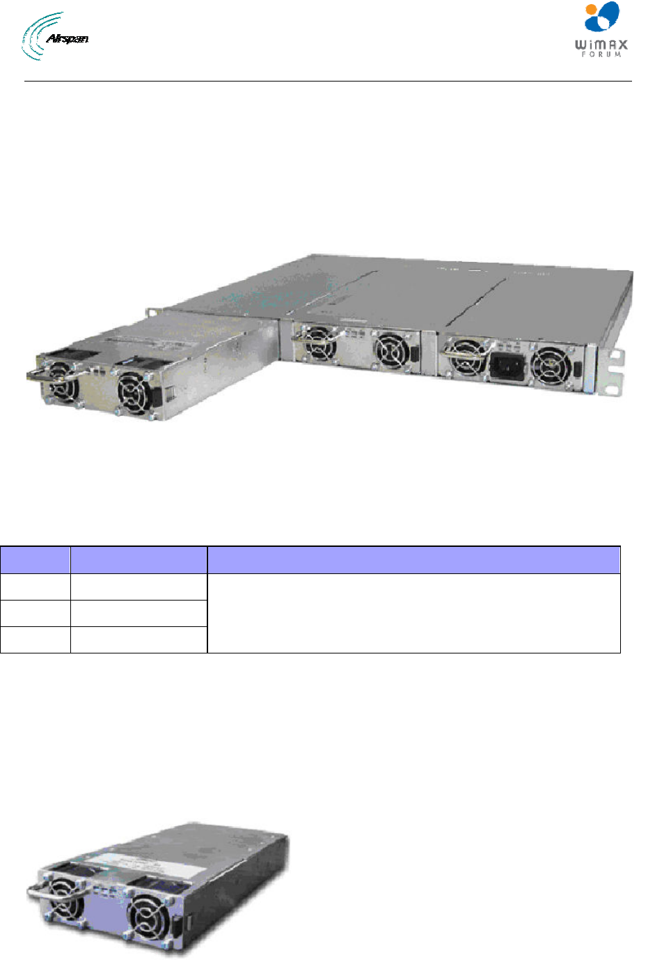
MicroMAX Hardware Installation User Guide
Page 43 Commercial in Confidence UWB-D00068 Rev J
8 AC/DC Power Converter
This section provides a description of the external AC/DC Power converter - Optional.
The third-party external AC/DC Power Converter is an optional unit that connects to the BSDU in
the event there is no -48VDC availability at the Base Station site (110/220 input). The AC/DC
Power Converter chassis fitted with one PS Unit for BSDU (PC-BSDU-1) supports up to 8 BSRs.
An additional PS unit is available (optional) for redundancy.
The figure below illustrates the AC/DC Power Converter's physical dimensions.
Figure 23 - AC/DC Power Converter
8.1.1 Physical Dimensions
The AC/DC power converter physical dimensions are described in the following table.
Table 21 - AC/DC power converter dimensions
Parameter Value Comment
Height 43.2 mm (1.7 inches)
Width 482.6 mm (19 inches)
Depth 228.6 mm (9 inches)
The physical dimensions exclude the bracket flanges for mounting.
8.2 Redundant PS Unit
The RPSU-BSDU-1 is a redundant PS Unit for the BSDU AC/DC power converter. The power
factor corrected (PFC) front ends provide a 48 VDC output for distributed power applications. The
small 1U by 2U size allows for configurations of either height in hot-swap redundant systems
while its internal fan and cooling design permits wide use with reliable operation.
The figure below illustrates the redundant PS Unit.
Figure 24 - RPSU-BSDU-1
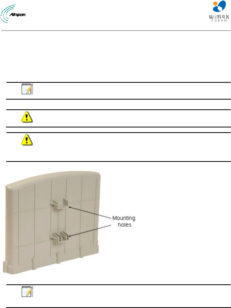
MicroMAX Hardware Installation User Guide
Page 44 Commercial in Confidence UWB-D00068 Rev J
9 Mounting the Base Station Radio (BSR)
The MicroMAX BSR can be pole-mounted or wall-mounted (optional). Pole mounting allows the
BSR to be easily adjusted in the horizontal (azimuth) and vertical (elevation) planes for antenna
alignment.
For either mounting method, the MicroMAX provides mounting holes (displayed in the figure
below), molded into its back panel for attaching the mounting brackets.
Note: The BSR fully complies with IP Code - IPX6 for product enclosure
protection.
Warning: The BSR device is an outdoor radio unit, and therefore, must only
be mounted outside.
Warning: Warning: Mount the MicroMAX in an orientation such that its ports
(located on the bottom panel) faces downwards. This prevents rain water
from settling on the ports, and thereby, avoiding damage to the unit such as
corrosion and electrical short-circuiting.
Figure 25 - BSR- rear view
Note: The standard BSR kit provides pole-mounting brackets. If you want to
wall-mount the MicroMAX, contact your Airspan distributor for pricing and
ordering of wall-mounting brackets.
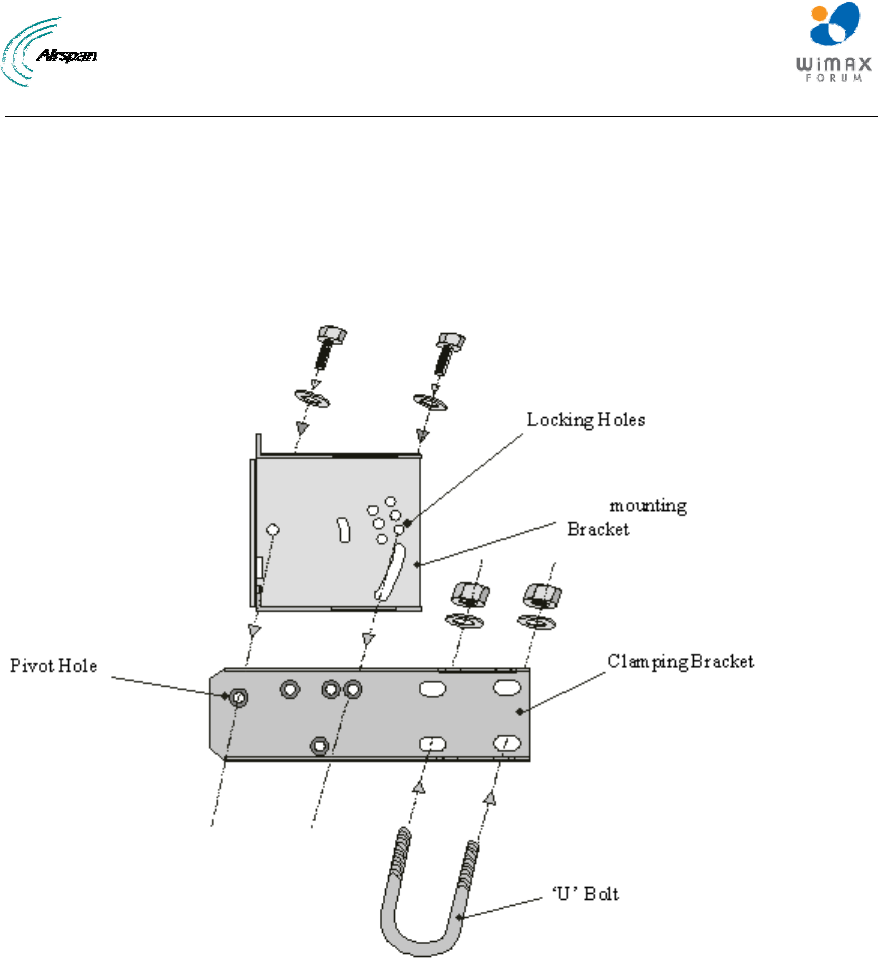
MicroMAX Hardware Installation User Guide
Page 45 Commercial in Confidence UWB-D00068 Rev J
9.1 Pole-Mounting the BSR
Pole mounting allows the MicroMAX to be easily adjusted in the horizontal (azimuth) and vertical
(elevation) planes for antenna alignment. The BSR is mounted using the mounting holes located
on the BSR's back panel and the supplied pole-mounting brackets. The pole-mounting bracket is
designed to support the BSR on a round pole of 45 mm in diameter.
The figure below summarizes of the MicroMAX's pole-mounting procedure.
Figure 26 - Pole mounting bracket
To pole mount the MicroMAX BSR:
8. Attach the mounting bracket to the MicroMAX:
a. Align the mounting bracket with the MicroMAX's mounting holes so that the mounting
bracket's side with the built-in nut is aligned with the BSR's mounting holes furthest from
the MicroMAX's bottom panel, as shown in the figure below.
b. Slide an M10-flat washer and M10-spring lock washer onto an M10-hex head screw
(ensure spring lock washer is closest to the bolt's head). From the external side, insert
the M10-hex head screw through the mounting bracket and MicroMAX's mounting holes.
Fasten the M10-hex head screw (one is provided with a built-in nut while the other
requires you to insert an M10-hex nut into the MicroMAX's mounting hole). After
alignment is completed, tighten bolts. Max torgue for M10 is 44Nm (32lbf.ft.).
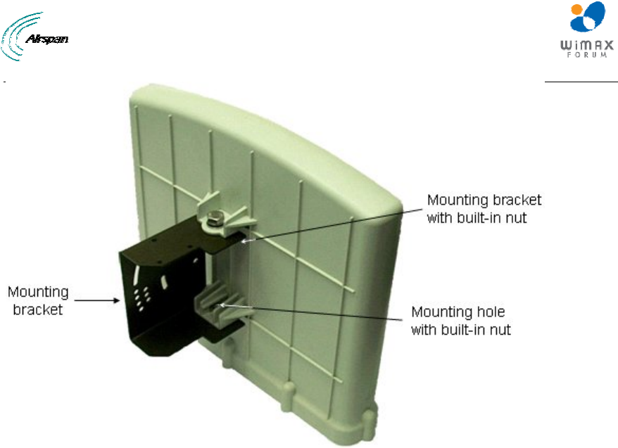
MicroMAX Hardware Installation User Guide
Page 46 Commercial in Confidence UWB-D00068 Rev J
Figure 27 - Mounting bracket attached
9. Attach the clamping bracket to the mounting bracket:
a. Slide an M6-spring lock washer onto an M6-hex head screw. Align the mounting
bracket's and clamping bracket's pivot holes, such that the clamping bracket is aligned to
the inside of the mounting bracket. From the external side of the mounting bracket, insert
the M6-hex head screw into the pivot holes and then fasten, but not tightly. (The
clamping bracket provides a built-in nut.)
b. Choose an elevation hole on the mounting bracket and then align it with the
corresponding hole on the clamping bracket. Slide an M6-spring lock washer onto an
M6-hex head screw, and then from the external side of the mounting bracket, insert the
M6-hex head screw through the elevation hole on the mounting bracket and into the
clamping bracket's corresponding hole. Fasten but not tightly the M6-hex head screw
(the clamping bracket provides built-in nut). The elevation hole can later be changed
according to desired antenna orientation in the elevation plane.
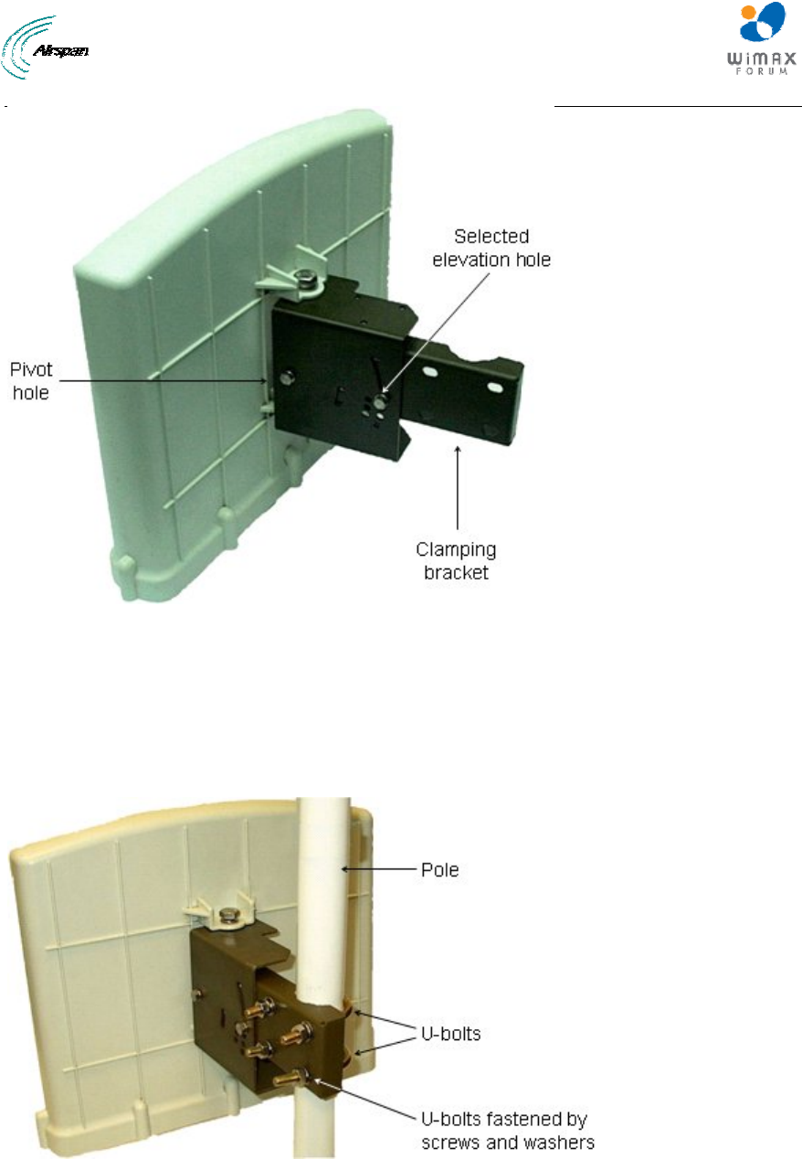
MicroMAX Hardware Installation User Guide
Page 47 Commercial in Confidence UWB-D00068 Rev J
Figure 28 - Pole mount clamping bracket
10. Attach the U-bolt to the pole:
3. Place one U-bolt around the pole, and then insert the U-bolt screw side through the two
corresponding holes (horizontally parallel) on the clamping bracket. Slide an M8-flat washer
and M8-spring lock washer onto each U-bolt screw side (ensure that the flat washer is
adjacent to the clamping bracket). Fasten each U-bolt side with the two M8-hex nuts.
d. Attach the second U-bolt as described above.
Figure 29 - Pole mount U-bolts
11. Perform final MicroMAX orientation:
a. Adjust the vertical position of the MicroMAX by choosing a final elevation hole as
described in Step 2. Lock the MicroMAX at the desired position by inserting the locking
bolt in the desired position and fastening it tightly. Fasten tightly the bolt in the pivot hole.
The figure below illustrates the angles (in degrees) of each elevation hole. As shown,
the MicroMAX pole-mounting bracket allows elevation between -18.5° and 26.3°.
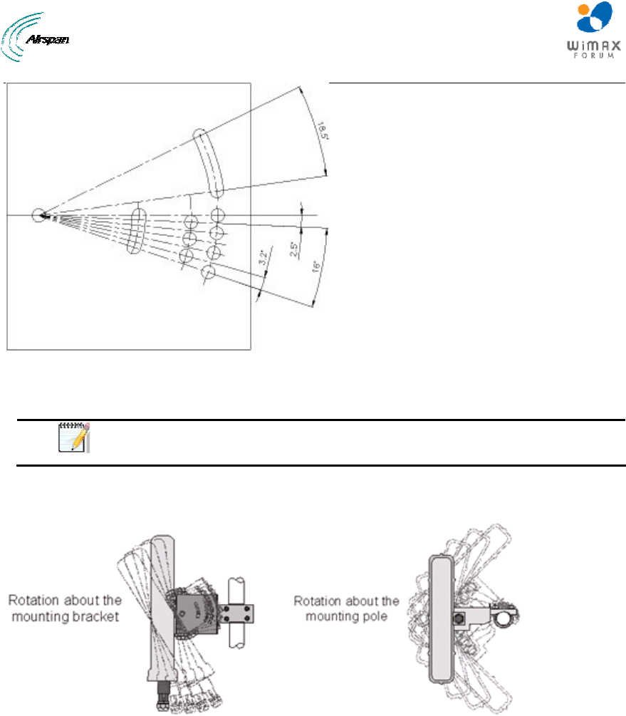
MicroMAX Hardware Installation User Guide
Page 48 Commercial in Confidence UWB-D00068 Rev J
Figure 30 - elevation holes
b. Adjust the horizontal position of the MicroMAX by rotating it about the pole, and then
tightening the nuts of the U-bolts.
Note: A thread-locking compound must be used to prevent the bolts from
working loose.
MicroMAX positioning is obtained in two planes by adjustment of the mounting bracket assembly
as shown below.
Figure 31 – positioning
It is important to provide strain relief and drip loop for Cat-5 cables. Create a drip loop and strain
relief using cable tie, to tie cable to pole, as displayed in the figure below:
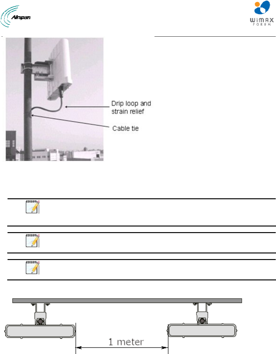
MicroMAX Hardware Installation User Guide
Page 49 Commercial in Confidence UWB-D00068 Rev J
Figure 32 - strain relief
9.2 Wall-Mounting the BSR (Optional)
Note: The standard BSR kit provides pole-mounting brackets. If you want to
wall-mount the MicroMAX BSR contact your Airspan distributor for pricing
and ordering of wall-mounting brackets.
Note: A minimum of 3 meter separation is required between MicroMAX and
existing customer radio equipment.
Note: A minimum of 1 meter separation should be maintained between
synchronized MicroMAXs (see figure below).
The figure below illustrates the minimum separation between synchronized MicroMAX's :
Figure 33 - mount separation
MicroMAX wall mounting consists of two main stages:
¾ Attaching the mounting bracket to the MicroMAX's mounting holes
¾ Attaching the mounting bracket (already attached to the MicroMAX) to the wall (or pole)
To wall mount the MicroMAX:
1. Position the unassembled mounting bracket on the mounting surface (e.g. wall), and then
use a pencil to mark the position of the four mounting holes. Ensure that the distance
between the hole centers are 120 mm (height) and 60 mm (width), as displayed in the figure
below showing the MicroMAX's fixing dimensions.
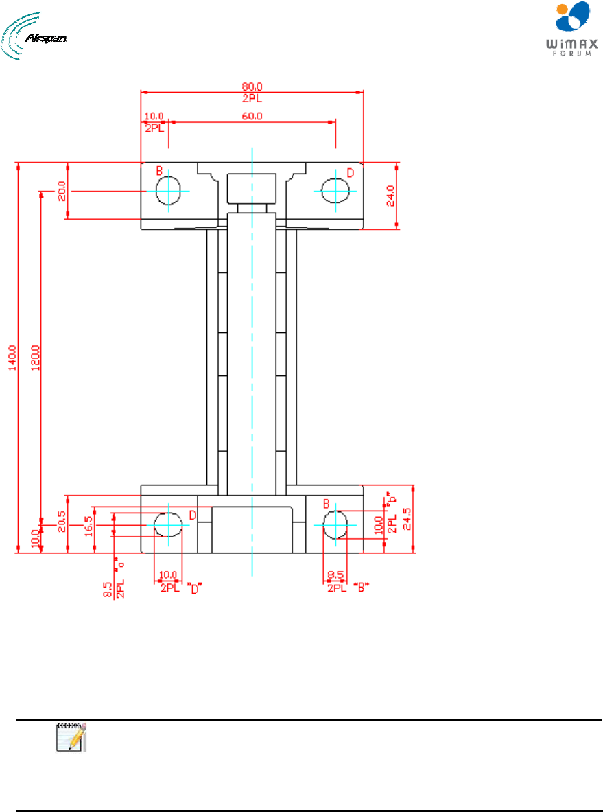
MicroMAX Hardware Installation User Guide
Page 50 Commercial in Confidence UWB-D00068 Rev J
Figure 34 - mounting template
2. Drill holes for each hole that you marked in the step above.
3. Insert wall anchors (not supplied) into each of the drilled holes.
4. Align the mounting bracket's four holes with the wall anchors, and then insert a screw (not
supplied) through the mounting bracket holes into each wall anchor, and then tighten.
Note: Airspan does not provide screws for attaching the mounting bracket to
the wall. The screw size depends on the structure of the building to which the
bracket is to be attached. When selecting screw sizes, consideration must be
given to the weight of the MicroMAX and load that may be induced in windy
conditions.
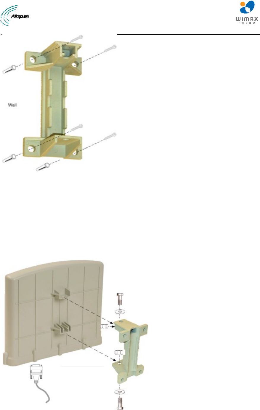
MicroMAX Hardware Installation User Guide
Page 51 Commercial in Confidence UWB-D00068 Rev J
Figure 35 - wall-mount bracket
5. Attach the MicroMAX to the mounting bracket by performing the following:
a. Slide an M10-spring lock washer and then an M10-plain washer onto each M10 x 1.5 hex
head screw (20mm length) – (ensure lock washer is nearest to head of screw bolt).
b. Align the mounting bracket's holes with the MicroMAX's mounting holes as displayed
below. (The mounting bracket side that provides a groove for inserting a nut must be
aligned with the MicroMAX's mounting hole that is nearest to the MicroMAX's bottom
panel.)
c. From the external sides, insert the M10-hex head screws through the mounting bracket's
holes and MicroMAX's mounting holes. Loosely fasten with the M10-hex nuts.
Figure 36 - attach mounting bracket
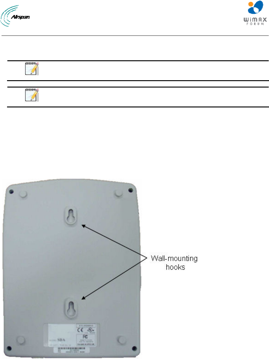
MicroMAX Hardware Installation User Guide
Page 52 Commercial in Confidence UWB-D00068 Rev J
5. Adjust the horizontal positioning of the MicroMAX (see "Web-Based Management" for
MicroMAX antenna alignment using RSS measurements), and then tighten the two M10 x
1.5-hex head screws (20mm length) with the M10 hex nuts.
Note: A third-party thread-locking compound must be applied to the M10-hex
head screws to prevent the bolts from working loose.
Note: For wall mounting, rotation is restricted in the horizontal plane only.
9.3 Installing the SDA-4S
The SDA-4S Type II (or SDA-4SDC Type II) is mounted vertically on a wall within the
communication center.
9.3.1 Wall Mounting
Wall mounting is made possible by the existence of two mounting hooks molded into the SDA-
4S's bottom panel, as displayed in the figure below.
Figure 37 - wall mount
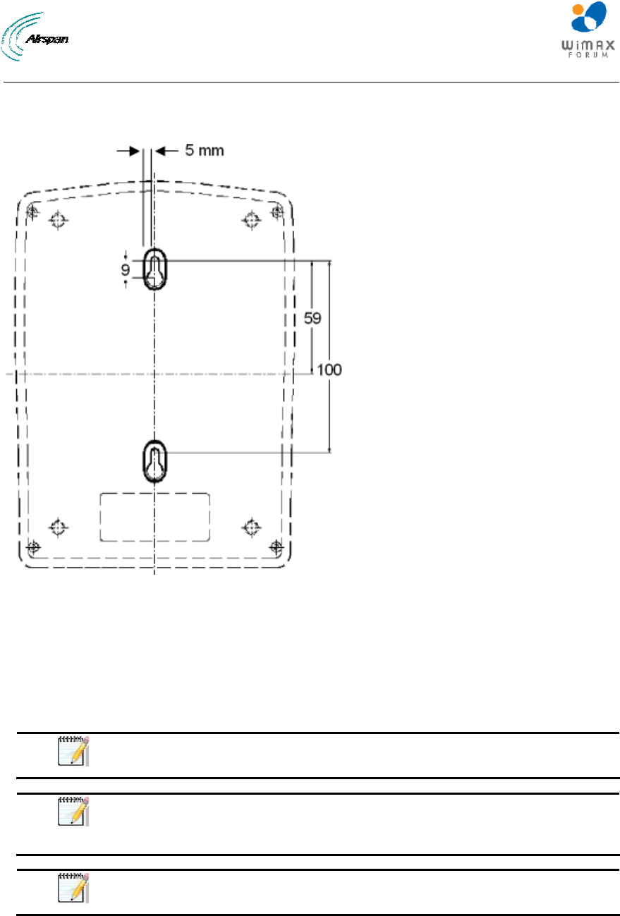
MicroMAX Hardware Installation User Guide
Page 53 Commercial in Confidence UWB-D00068 Rev J
To wall mount the SDA-4S:
On the wall, mark the position of the two mounting hooks. The dimensions of the wall-mounting
hooks are displayed in the template below.
Figure 38 - SDA-4S mounting template
6. Drill holes for each hole that you marked in the step above.
7. Insert wall anchors (supplied) into each of the drilled holes.
8. Insert the 9-inch screws (supplied) into the wall anchors. Ensure at least 2 mm of the screw
is exposed to allow insertion into the SDA-4S mounting holes.
9. Hold the SDA-4S with both hands, and align the entrance to the two mounting hooks with the
screws. Slide the screws into the mounting hooks, by lowering the SDA-4S onto the screws.
Note: For safety, both mounting hooks must be utilized when mounting the
unit.
Note: The SDA-4S is supplied with a 1-metre AC power lead assembly.
Therefore, ensure the unit is mounted within reachable distance to the
customer's mains power outlet.
Note: The maximum cable run between SDA-4S and MicroMAX is 100
meters. Therefore, ensure the unit is mounted within reachable distance.
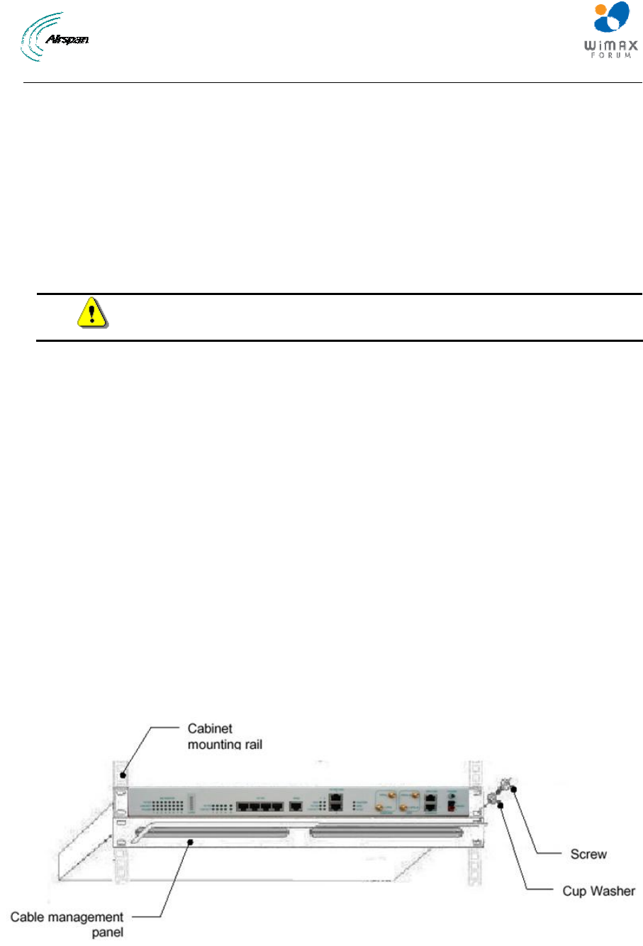
MicroMAX Hardware Installation User Guide
Page 54 Commercial in Confidence UWB-D00068 Rev J
10 Mounting the BSDU
The BSDU can be mounted in either of the two (2) following ways:
¾ Horizontally on a desktop
¾ Horizontally in a rack (ETSI or 19“)
10.1 Desktop mounting
The BSDU can simply be placed horizontally on a table. You can attach to the BSDU's bottom
panel, four rubber feet (pads) (supplied) on each corner to provide cushioning and insulation from
static electricity.
Warning: To prevent a fire hazard caused by overheating, do not place the
BSDU on a surface where airflow is restricted.
10.2 Rack mounting
The BSDU is designed for mounting in a standard 19-inch (48.3 cm) ETSI equipment rack or telco
rack with 1-rack unit (1-U) of vertical rack space. Mounting bracket flanges are provided for
mounting the BSDU into the cabinet, in its kit. Therefore, all that is required for mounting the
BSDU is to attach the BSDU front-rail mounting brackets to the rack's mounting rails using the
supplied four M5-mounting screws and plastic cup washers.
To rack-mount the BSDU:
1. Determine the rack rail holes (left and right side) that will be used for attaching the chassis.
2. Insert four nuts into the rack's rail holes you designated in Step 1. These nuts are housed in
Tinnerman clips, which allow you to fasten them into the rail holes. To insert the Tinnerman
clips, hold the clips, squeeze them, and then insert them into the rail hole.
3. Carefully insert the BSDU into the rack, aligning the BSDU's mounting bracket holes with the
rack rail holes.
4. Insert the M5-mounting screws, with plastic washers, into the BSDU mounting bracket holes,
on each side, as shown in figure below. In this way, the chassis is supported until you tighten
the chassis screws.
5. Tighten the M5-mounting screws to fasten the chassis to the cabinet.
Figure 39 - Rack mounted

MicroMAX Hardware Installation User Guide
Page 55 Commercial in Confidence UWB-D00068 Rev J
Note: When mounting multiple BSDUs in a cabinet, vertical spacing (above
and below) is required for feeding cables to the rear.
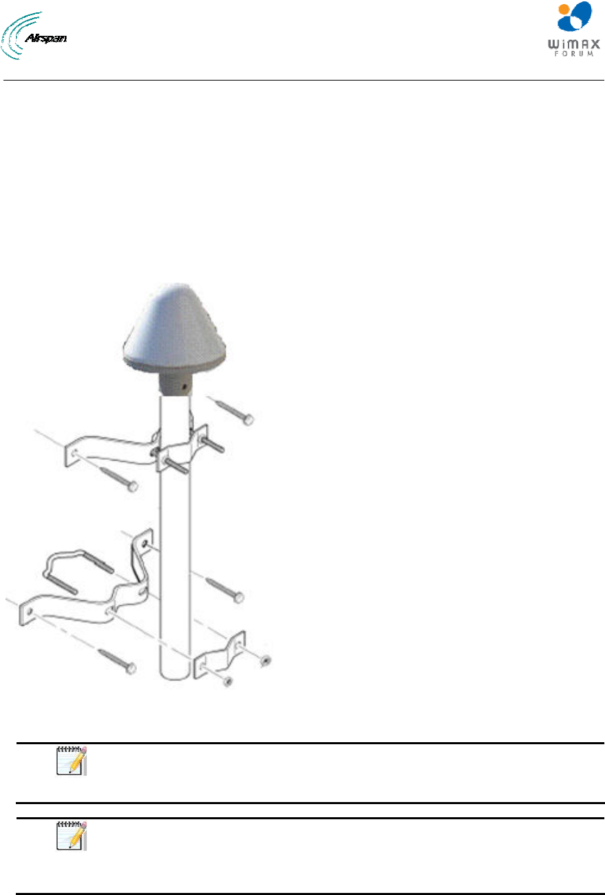
MicroMAX Hardware Installation User Guide
Page 56 Commercial in Confidence UWB-D00068 Rev J
11 Mounting the GPS
Depending on individual customer requirements and environmental influences, there are several
available options for mounting the GPS:
¾ Pole Mounting: Using the 1" – 14 threads, the GPS can be mounted onto a standard
antenna mast or mounting adapter. (not supplied)
¾ Mounting Plate: Using three 10-32 UNF screws, the GPS can be mounted on a flat
surface with three holes on a 1.75-inch diameter circle. (not supplied)
¾ Direct Mounting: The unit may be mounted directly to a suitable structure that has been
provided with holes suited to the GPS mounting details.
Figure 40 - GPS pole mounting
Note: When mounting the GPS on a metal pole that is in physical contact
with the ground, the GPS will not synchronize. To enable synchronization,
you need to isolate the GPS from the pole using isolation material.
Note: The GPS should not be mounted near to FM transmitters, whether
broadcast radio, or 2-way radio, as this can cause a loss of sync. Mount the
GPS away from the transmitting antenna, or physically shield from the
transmitting antenna, this will assist with proper GPS operation.

MicroMAX Hardware Installation User Guide
Page 57 Commercial in Confidence UWB-D00068 Rev J
12 Mounting the AC/DC Power Converter
The AC/DC Power Converter is to be mounted horizontally in a rack (ETSI or 19“)
12.1 Rack Mounting
The AC/DC Power Converter is designed for mounting in a standard 19-inch (48.3 cm) ETSI
equipment rack or telco rack with 1-rack unit (1-U) of vertical rack space. Mounting bracket
flanges are provided for mounting the AC/DC Power Converter into the cabinet, in its kit.
Therefore, all that is required for mounting the AC/DC Power Converter is to attach the AC/DC
Power Converter front-rail mounting brackets to the rack's mounting rails using the four M5-
mounting screws and plastic cup washers.
To rack-mount the AC/DC Power Converter:
1. Determine the rack rail holes (left and right side) that will be used for attaching the chassis.
2. Insert four nuts into the rack's rail holes you designated in Step 1. These nuts are housed in
Tinnerman clips, which allow you to fasten them into the rail holes. To insert the Tinnerman
clips, hold the clips, squeeze them, and then insert them into the rail hole.
3. Carefully insert the AC/DC Power Converter into the rack, aligning the AC/DC Power
Converter's mounting bracket holes with the rack rail holes.
4. Insert the M5-mounting screws, with plastic washers, into the AC/DC Power Converter
mounting bracket holes, on each side, as shown in figure below. In this way, the chassis is
supported until you tighten the chassis screws.
5. Tighten the M5-mounting screws to fasten the chassis to the cabinet.
12.2 Connecting Redundant PS Unit
When required an additional PS unit is available (optional) for redundancy. This hot-swappable
unit is designed for ease of installation.
To install an additional PS unit
1. Check that the recessed on/off switch is in the off position
2. Determine the location to mount the redundant PS unit in the AC/DC Power Converter's
chassis housing (usually to the left on the presently installed unit).
3. Carefully slide the unit on the rail tray until flush with front of AC/DC Power Converter's
chassis housing.
4. Secure the unit by turning the Latch Lock screw, using a flat screw driver
5. Set the DIP switches (located on the back of the PS unit) to the on position for all 5 switches.
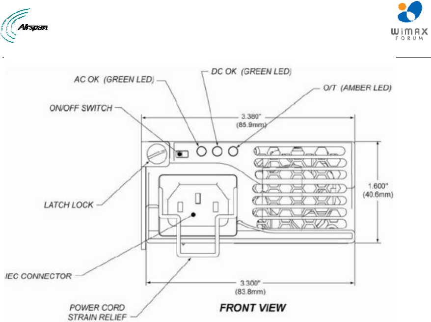
MicroMAX Hardware Installation User Guide
Page 58 Commercial in Confidence UWB-D00068 Rev J
Figure 41 - PSU front
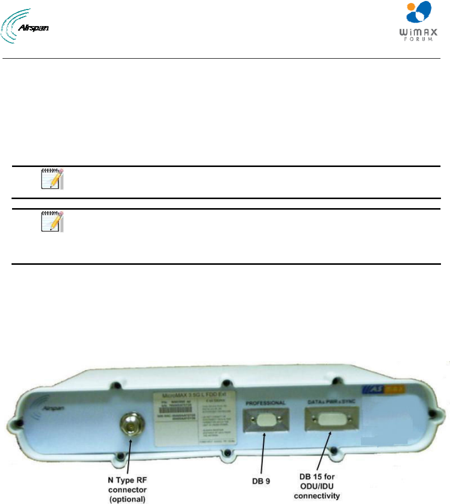
MicroMAX Hardware Installation User Guide
Page 59 Commercial in Confidence UWB-D00068 Rev J
13 Cabling the BSR
Network cabling at the Base Station depends on the devices implemented to provide the BSR
with connectivity to the provider's backhaul and power source. These devices can be one of the
following:
¾ SDA: AC/DC powered and consisting of a single BSR
¾ BSDU: AC/DC powered and consisting of multiple BSRs
Note: SFTP (Shielded Foiled Twisted Pair) CAT-5e outdoor cable is
recommended.
Note: If FM interference is discovered during installation, install a Ferrite
suppressor on the CAT-5e cable, near BSR. See Lightning and Surge
Protection. Refer to Commissioning Guide (Troubleshooting section) for
further instructions.
13.1 Connecting the BSR to the SDA-4S
The SDA-4S provides -48 VDC power to the BSR as well as the Fast Ethernet interface between
the BSR and the provider's backhaul network. The outdoor Base Station Radio and modem are
powered over a CAT-5e cable by the SDA-4S Type II IDU (or the SDA-4SDC) in the minimum
configuration. For larger configurations N* SDA-4Ss and N* BSRs are required or connection to
BSDU(s).
Figure 42 - BSR front panel
The BSR interfaces with the subscriber's Ethernet network through the SDA-4S. To connect the
BSR to the SDA-4S, you need to connect the BSR's 15-pin D-type port to the SDA-4S's 15-pin D-
type port using CAT-5e cable.
The cable setup for MicroMAX-to-SDA-4S connectivity is as follows:
¾ Cable: Straight-through CAT-5e Ethernet cable
¾ Connectors:
• MicroMAX: DB15-to-RJ45 outdoor adapter (black color)
• SDA-4S: DB15-to-RJ45 indoor adapter (for connecting to DATA&PWR&SYNC D-type
connector)
• CAT-5e cable with 8-pin RJ-45 male connectors on either end
¾ Connector pinouts:
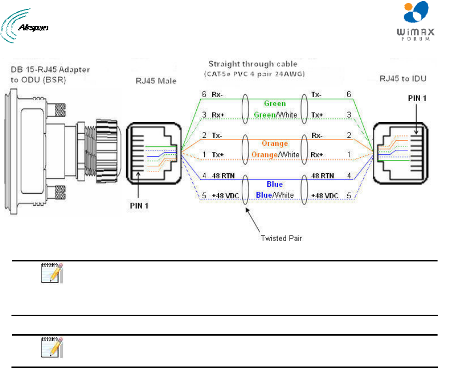
MicroMAX Hardware Installation User Guide
Page 60 Commercial in Confidence UWB-D00068 Rev J
Figure 43 - Pinouts
Note: The wire color-coding described in the table is Airspan's standard for
wire color-coding. However, if you implement your company's wire color-
coding scheme, ensure that the wires are paired and twisted according to pin
functions listed in the table above (e.g. Rx+ with Rx-).
Note: The maximum CAT-5e cable length for ODU/IDU connectivity is 100
meters.
To connect the BSR to the SDA-4S:
1. Connect the 15-pin D-type male connector, at one end of the CAT-5e cable, to the BSR's 15-
pin D-type port labeled DATA&PWR&SYNC.
2. Connect the 15-pin D-type male connector, at the other end of the CAT-5e cable, to the
SDA-4S's 15-pin D-type port.
13.2 SDA-4S Type II
The SDA-4S Type II (or the SDA-4SDC) provides one to four RJ-45 (100BaseT) ports for
interfacing with the subscriber's LAN network.
The ports of the SDA-4S model support Auto Negotiation, allowing automatic configuration for the
highest possible speed link (10BaseT or 100BaseT), and Full Duplex or Half Duplex mode. In
other words, the speed of the connected device (e.g. PC) determines the speed at which packets
are transmitted through the specific port. For example, if the device to which the port is connected
is running at 100 Mbps, the port connection will transmit packets at 100 Mbps. Conversely, if the
device to which the port is connected is running at 10 Mbps, the port connection will transmit
packets at 10 Mbps
In addition, the SDA-4S ports support MDI/MDI-X automatic crossover, allowing connection to
straight-through or crossover CAT-5e cables. Therefore, these ports can be connected to either a
hub (i.e. using crossover cables) or a PC (i.e. using straight-through cables).
The cable setup for SDA-4S LAN connectivity is as follows:
¾ Cable: Straight-through (e.g. when connecting to PC) or crossover (i.e. when connecting
to a hub) CAT-5e Ethernet cable
¾ Connectors: 8-pin RJ-45 at both ends
¾ Connector pinouts:
• Straight-through cable (e.g. connecting to a PC)
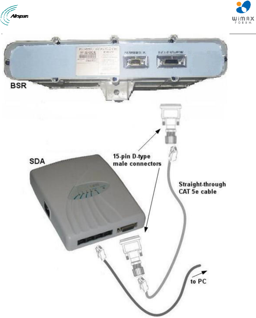
MicroMAX Hardware Installation User Guide
Page 61 Commercial in Confidence UWB-D00068 Rev J
Figure 44 - BSR – SDA
13.3 Connecting the BSR to BSDU
The BSR's 15-pin D-type port is connected to one of the eight BSDU's rear panel 15-pin D-type
ports (labeled Radio 8-1).
The BSR-to-BSDU cable setup is as follows:
¾ Cable: straight-through 10/100 Base-T Ethernet 4 Pair CAT-5e outdoor type – 22 AWG
(100 meters)
¾ Connectors:
• BSR side: 15-pin D-type male (only 8 pins are used)
• BSDU side: 15-pin D-type male (only 8 pins are used)
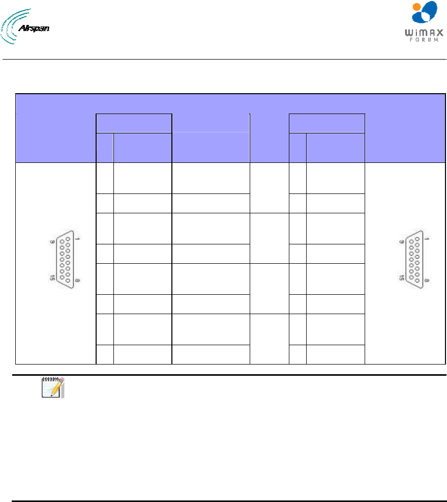
MicroMAX Hardware Installation User Guide
Page 62 Commercial in Confidence UWB-D00068 Rev J
¾ Connector pinouts:
Table 22 - BSR- BSDU connections
Straight-through CAT-5 PVC 4 Pair 24 AWG cables
BSR BSDU 15-pin D-type
male Pin Function
Wire color Wire
pair PinFunction
15-pin D-type
male
1 +48
VDC
Blue / White 1 +48
VDC
2 48 RTN Blue
1
2 48 RTN
3 Tx+ Orange /
White
3 Rx+
4 Tx- Orange
2
4 Rx-
5 Rx+ Green /
White
5 Tx+
6 Rx- Green
3
6 Tx-
7 Sync.+ Brown /
White
7 Sync.+
8 Sync.- Brown
4
8 Sync.-
Note: A CAT-5e cable connects to the 15-pin D-type port; therefore, only
eight pins are used (i.e. pins 9 through 15 are not used).
The wire color-coding described in the table (and shown in the figure below)
is AIRSPAN WIMAX's standard for wire color-coding. However, if you
implement your company's wire color-coding scheme, ensure wires are
paired and twisted according to pin functions (e.g. Rx+ with Rx-).
When the BSR is connected to an SDA, pins 7 and 8 are not used (i.e. no
synchronization).
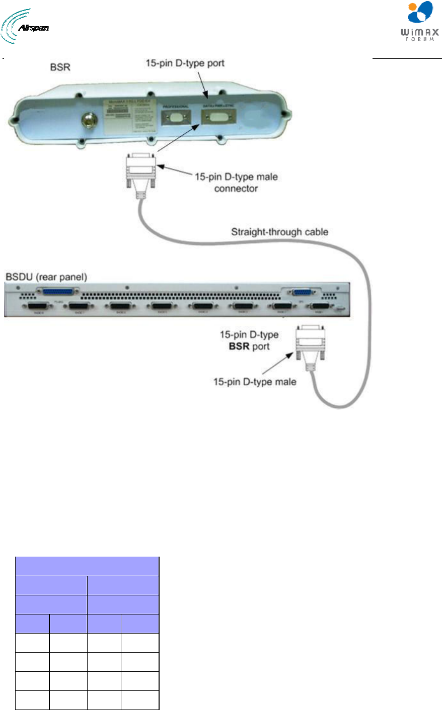
MicroMAX Hardware Installation User Guide
Page 63 Commercial in Confidence UWB-D00068 Rev J
Figure 45 - BSR-to-BSDU cable connection
13.4 Connecting BSDU to Network
The BSDU's front panel provides two 10/100/1000 Base-T RJ-45 ports (labeled 1 & 2). These
ports are used for connecting to the service provider's backbone (WAN).
¾ Cable: straight through
¾ Connector: 8-pin RJ-45
¾ Connector pinouts:
Table 23 - BSDU-to-WAN cable connector pinouts
Straight-through cable
BSDU WAN
8-pin RJ 45 8-pin RJ 45
Pin Signal Pin Signal
1 Tx+ 1 Rx+
2 Tx- 2 Rx-
3 Rx+ 3 Tx+
6 Rx- 6 Tx-
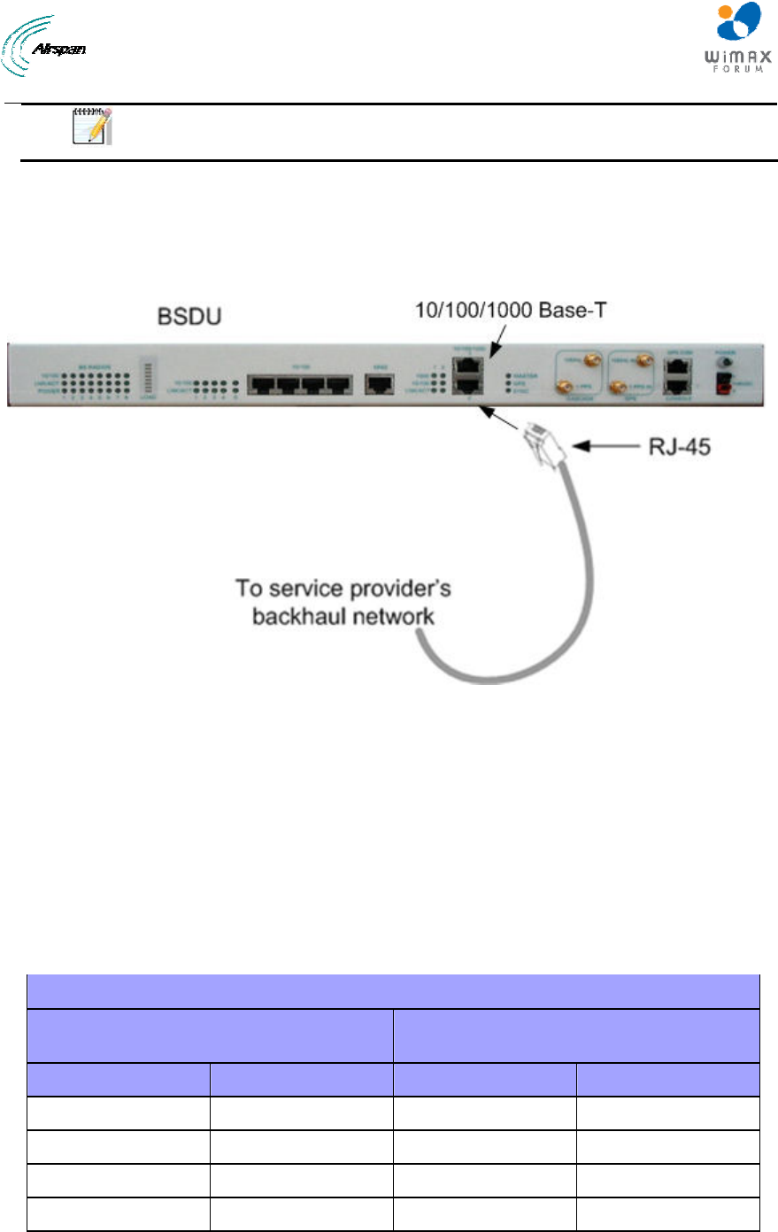
MicroMAX Hardware Installation User Guide
Page 64 Commercial in Confidence UWB-D00068 Rev J
Note: Pins not defined are not used.
To connect the BSDU's 10/100/1000 Base-T ports to the provider's backbone:
1. Connect the 8-pin RJ-45 connector, at one end of the cable, to no. 1 of the BSDU's
10/100/1000 Base-T ports, (labeled 1).
2. Connect the other end of the cable to the backbone network.
Figure 46 - BSDU-to-backhaul network
13.5 Connecting BSDUs
You can connect two (2) BSDUs at a Base Station. You can connect BSDUs by connecting the
10/100/1000 Base-T ports between BSDUs using a crossover cable.
The following lists the cable setup for BSD chaining:
¾ Cable: RJ-45-to-RJ-45 crossover
¾ Connector: 8-pin RJ-45
¾ Connector pinouts:
Table 24 - BSDU connecting cable connector pinouts
Crossover cable
8-PIN RJ 45
(BSDU'S 10/100/1000 BASE-T PORT) 8-PIN RJ 45
(BSDU'S 10/100/1000 BASE-T PORT)
Pin SIGNAL Pin SIGNAL
1 Tx+ 1 Rx+
2 Tx- 2 Rx-
3 Rx+ 3 Tx+
6 Rx- 6 Tx-
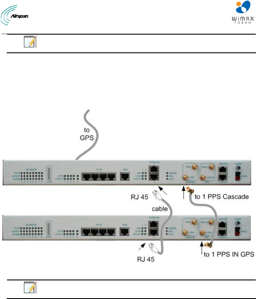
MicroMAX Hardware Installation User Guide
Page 65 Commercial in Confidence UWB-D00068 Rev J
Note: Pins not defined are not used.
To chain BSDUs:
1. On the first BSDU, connect the RJ-45 connector, at one end of the crossover cable, to one of
the two 10/100/1000 Base-T ports (labeled 1 or 2) located on the BSDU's front panel.
2. On the second BSDU, connect the RJ-45 connector, at the other end of the crossover cable,
to one of the two BSDU's 10/100/1000 Base-T ports (labeled 1 or 2) located on the BSDU's
front panel.
Figure 47 - Cable connections for BSDU chaining with GPS
Note: When connecting BSDU's it does not matter which one of the two
10/100/1000 Base-T ports you use two connect two BSDUs.
13.6 Connecting BSDU for SNMP Management
To configure the BSDU, or BSRs connected to the BSDU, through an IP network communication
mode, you can connect the BSDU directly to the PC, or remotely (from anywhere) if you have IP
connectivity to the PC.
For PC-to-BSDU local network connections you need to connect the PC to the BSDU's
management port.
The following lists the cable setup for BSDU local network management:
¾ Cables:
• Straight-through for connecting the PC to the BSDU management port
¾ Connector: 8-pin RJ-45
¾ Connector pinouts:
Table 25 - BSDU to PC for IP network management
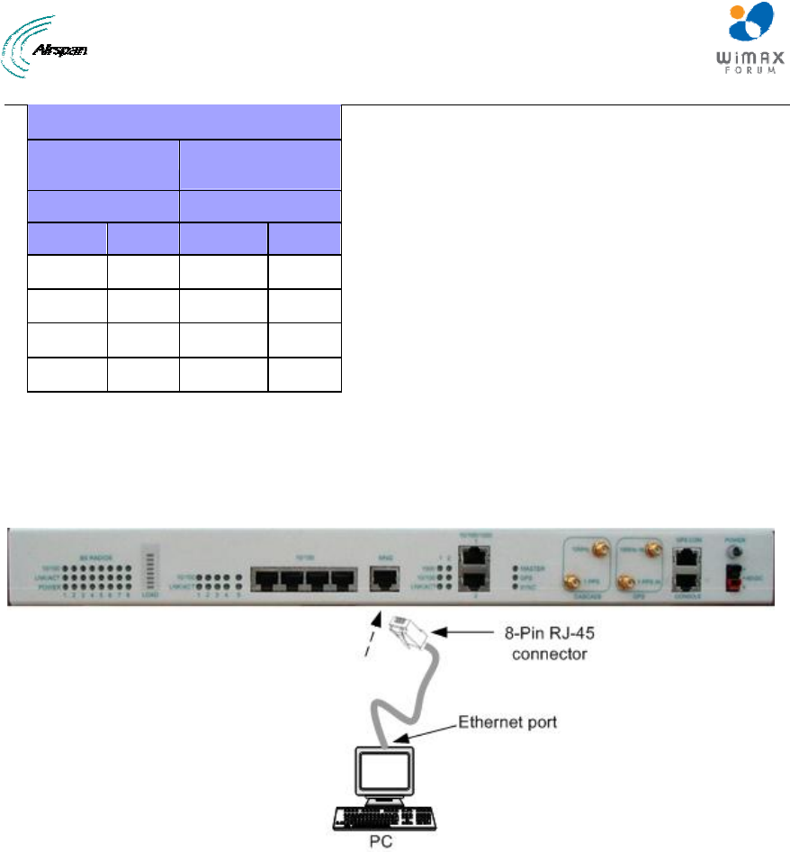
MicroMAX Hardware Installation User Guide
Page 66 Commercial in Confidence UWB-D00068 Rev J
Straight-through cable
PC LAN port BSDU
management port
8-pin RJ 45 8-pin RJ 45
Pin Signal
Pin Signal
1 Tx+ 1 Rx+
2 Tx- 2 Rx-
3 Rx+ 3 Tx+
6 Rx- 6 Tx-
To connect the BSDU to PC for IP network management
1. Connect the RJ-45 connector, at one end of the straight-through cable, to the BSDU's
management port.
2. Connect the RJ-45 connector, at the other end of the straight-through cable, to the PC's LAN
port.
Figure 48 - BSDU-to-PC local network management cabling

MicroMAX Hardware Installation User Guide
Page 67 Commercial in Confidence UWB-D00068 Rev J
14 Connecting the SDA-4S to the power supply
14.1 Connecting the SDA-4S Type II
The SDA-4S adapter is plugged into a standard electrical wall outlet (110/240 VAC) using an AC
power cord. The appropriate AC power cord is supplied according to the country of use.
The cable setup between the SDA-4S and power outlet includes the following:
¾ Connector: AC IEC 60320 type (female)
¾ Plug: The appropriate plug type is supplied according to the country of use
¾ Cable: 3x1.z0 mm, 10A / 250 VAC (maximum length is 180 cm)
Figure 49 - Power chord
To connect the SDA-4S to the AC power supply:
1. Connect the power plug female, at the end of the AC power chord, into the AC power socket
located on the left panel of the SDA-4S.
2. Plug the power plug male, at the other end of the AC power chord, into the AC power outlet
(110-240 VAC).
3. Verify that the power is received by the SDA-4S by checking that the POWER LED light is
on.
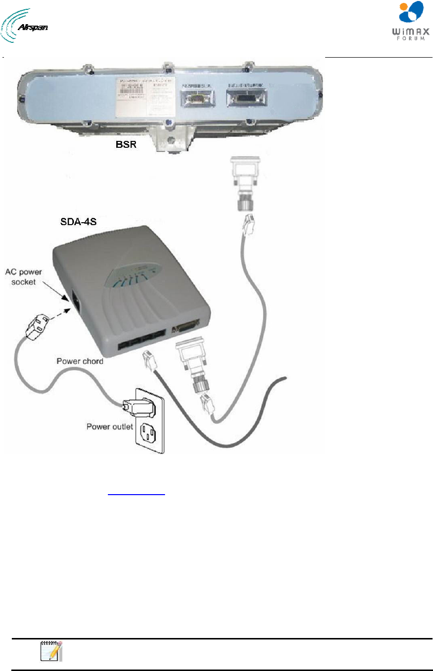
MicroMAX Hardware Installation User Guide
Page 68 Commercial in Confidence UWB-D00068 Rev J
Figure 50 - Connecting to AC power
4. Verify that your SDA-4S is on and receiving power by checking that the LED labeled
POWER is lit (see SDA-4S LED description).
14.2 Connecting the SDA-4SDC Type II
The SDA-4SDC adapter is connected to the DC power supply using a cable appropriate to the
specific field conditions.
The setup between the SDA-4SDC and power connection includes the following:
¾ Connector: Anderson Connector Housings for connecting the cable to the SDA-4SDC
DC power socket.
• 1327 - Red Housing x 1
• 1327G6 - Black Housing x 1
Note: Due to the variety of on-site conditions the cable is not supplied and
should be acquired per specific connection needs.
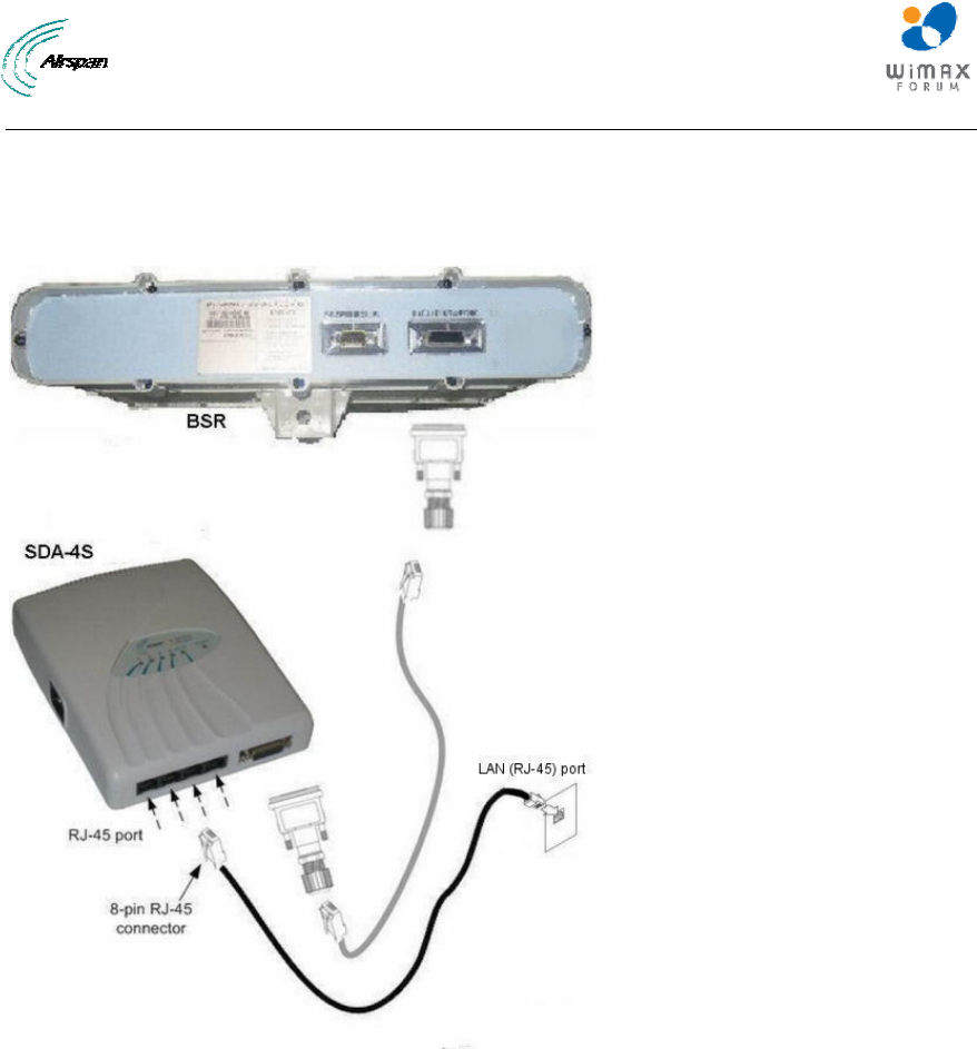
MicroMAX Hardware Installation User Guide
Page 69 Commercial in Confidence UWB-D00068 Rev J
14.3 Connecting SDA-4S to Ethernet Network
The MicroMAX typically interfaces with the subscriber's network/computer using the SDA-4S or
SDA-4SDC Type II which provides four (10/100BaseT) LAN ports for interfacing with the
subscriber's LAN network.
Figure 51 - Connect to Ethernet
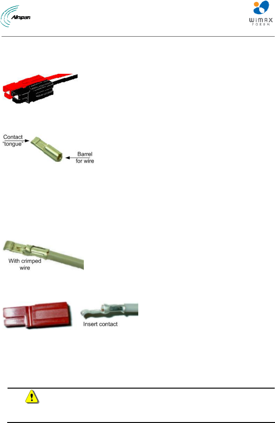
MicroMAX Hardware Installation User Guide
Page 70 Commercial in Confidence UWB-D00068 Rev J
15 Connecting Power Cable for SDA-4SDC
In the SDA-4SDC installation Kit there are two polarized and genderless unassembled Anderson
Powerpole power connectors: red for positive connection and black for the negative connection.
Figure 52 - Power connectors (Anderson Powerpole)
The power connectors consist of housing (hood and a contact pins). The contact pin is displayed
below:
Figure 53 - Contact pin
15.1 Housing the Connectors
The power connectors are supplied unassembled. Therefore, you need to crimp the power wires
to the connector's contact pins, and then house them in the Powerpole hood.
Crimping the power wires to the connectors:
1. Insert the wire into the contact pin's barrel, and then, with a standard crimping tool crimp the
barrel tightly onto the wire (recommended 16 AWG cable wire).
Figure 54 – crimped
2. Insert the contact into the hood with the contact's tongue pointing downwards and snap
into place. Ensure that the housing spring mates with the underside of the contact's tongue.
Figure 55 – Insertion
15.2 Connecting to the SDA-4SDC
Once you have crimped the power cord to the Powerpole connectors, connect the power
connectors to the SDA-4SDC power receptacles.
To connect the power cord to the SDA-4SDC:
Caution: The plastic housings are held together with dovetail joints. Always
slide these joints together! They will be damaged if you try to snap them
together or apart. They ONLY slide together in one direction. This should be
obvious by looking at them carefully.
1. Assemble the red and black plastic housings together. Mate both connectors, by sliding
them along the dovetail joints.
When looking at the connector side (not the wire side), the red connector should be on the
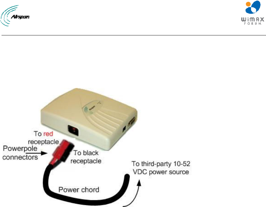
MicroMAX Hardware Installation User Guide
Page 71 Commercial in Confidence UWB-D00068 Rev J
left and the black on the right.
The housing dovetails should be mated fully.
2. Connect the power connectors to the SDA-4SDC power receptacles so that the connectors'
color matches the receptacle's color, red to red (positive), and black to black (negative).
3. Connect the other end of the power cord to the third-party DC power source. Ensure that the
positive and negative sides are correct.
Figure 56 - Connect to power source
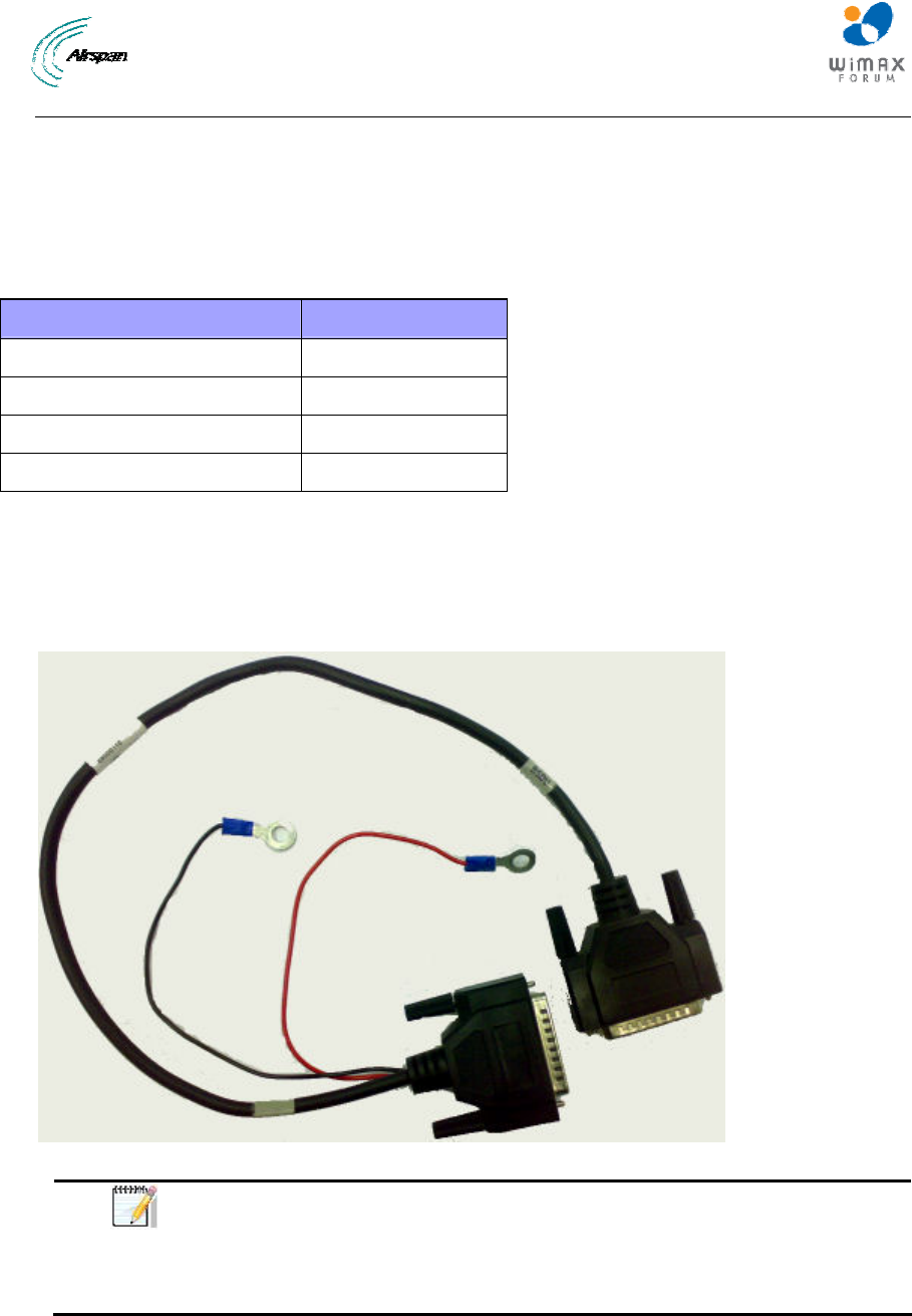
MicroMAX Hardware Installation User Guide
Page 72 Commercial in Confidence UWB-D00068 Rev J
16 Connecting BSDU to AC/DC Power converter
This section provides a description of how to connect the Base Station Distribution Unit (BSDU)
to the external AC/DC Power converter. This section explains the steps needed to connect the
two units together for proper functioning.
Table 26 - Required Equipment
Equipment Description Part number
BSDU MMX-BSDU-1
AC/DC Converter PC-BSDU-1
BSDU to AC/DC Converter Cable 68000110
BSDU to DC power Supply Cable supplied with BSDU kit
16.1 Connections
There are two sets of cables required for the BSDU and AC/DC converter to work properly.
¾ Cable with 25-pin D-type Male to 25-pin D-Type Male (part no. 68000110) with 2 cables
(UL 20AWG red color and UL 20AWG black color both with ring terminals).
Figure 57 - BSDU - AC/DC cable
Note: This cable connects between the rear panels of the BSDU and the
AC/DC converter. It also has connections to the main DC Output of the
AC/DC converter, but the cable itself DOES NOT carry power to the BSDU.
These connections are used for sensing purposes, so that the PSU can
adjust the DC output according to the load drawn by the BSDU.
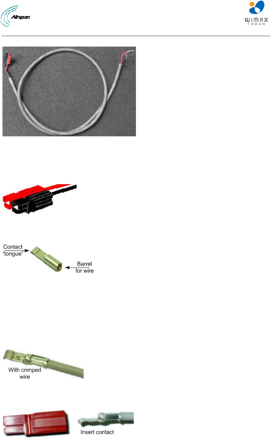
MicroMAX Hardware Installation User Guide
Page 73 Commercial in Confidence UWB-D00068 Rev J
¾ BSDU to DC power supply cable (supplied with the BSDU)
Figure 58 - BSDU to DC cable
16.2 Power Cable Assembly
In the BSDU Kit there are two polarized and genderless unassembled Anderson Powerpole
power connectors: red for positive connection and black for the negative connection.
Figure 59 - Power connectors (Anderson Powerpole)
The power connectors consist of housing (hood and a contact pins). The contact pin is displayed
below:
Figure 60 - Contact pin
16.3 Housing the Connectors
The power connectors are supplied unassembled. Therefore, you need to crimp the power wires
to the connector's contact pins, and then house them in the Powerpole hood.
Crimping the power wires to the connectors:
1. Insert the wire into the contact pin's barrel, and then, with a standard crimping tool crimp the
barrel tightly onto the wire (recommended 20AWG cable wire).
Figure 61 – Crimped
2. Insert the contact into the hood with the contact's tongue pointing downwards and snap
into place. Ensure that the housing spring mates with the underside of the contact's tongue.
Figure 62 - Insertion
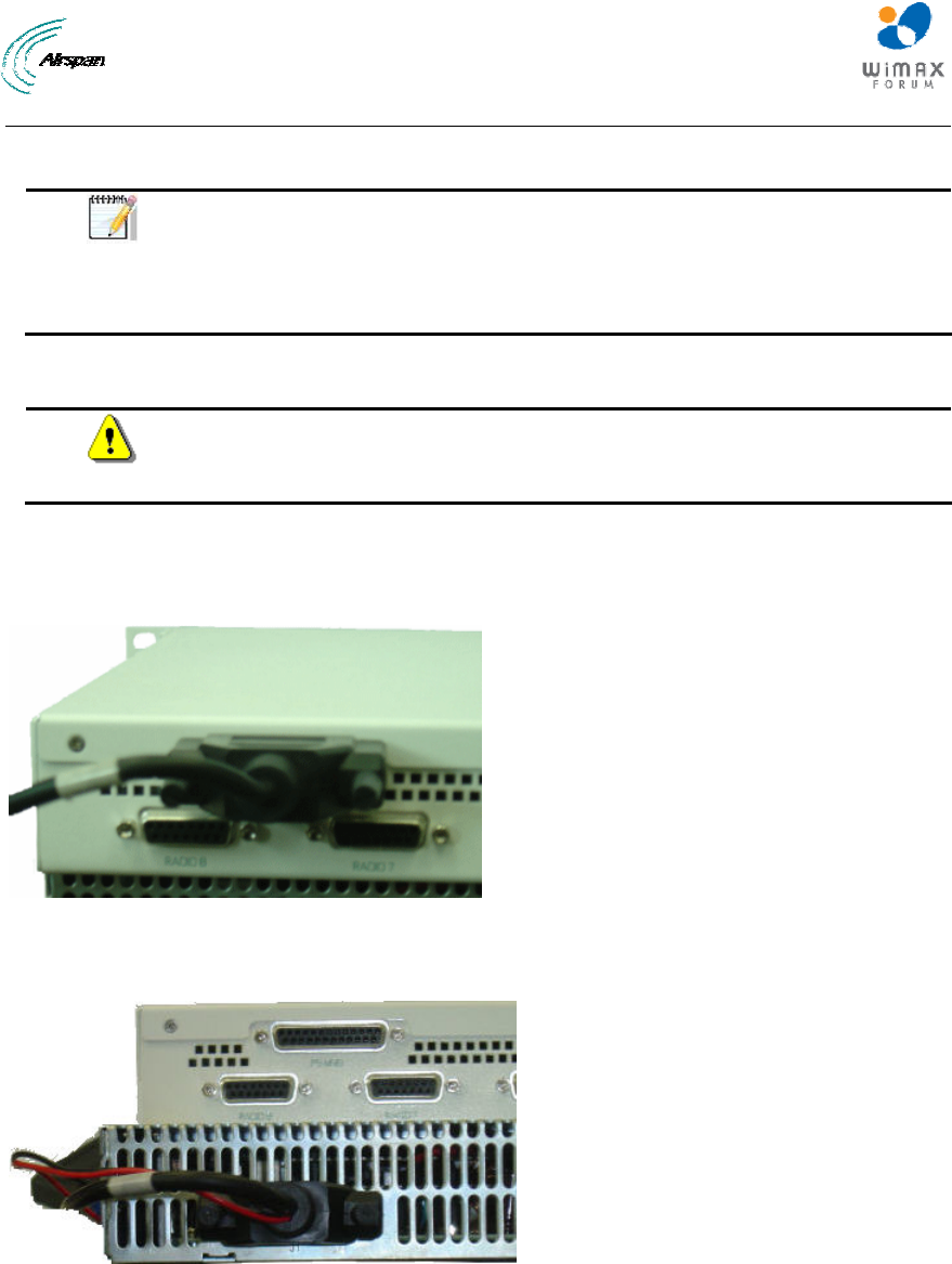
MicroMAX Hardware Installation User Guide
Page 74 Commercial in Confidence UWB-D00068 Rev J
This cable connects between the rear panel of the AC/DC Converter and the -48V Power Input on
the Front Panel of the BSDU.
Note: Ensure that:
The POSITIVE output of the AC/DC Converter is connected to the POSITIVE
(Red) input (lower) on the BSDU.
The NEGATIVE output of the AC/DC Converter is connected to the
NEGATIVE (Black) input (upper) on the BSDU.
16.4 Cable Connection
Caution: Confirm that all inputs to the AC/DC converter are either
disconnected or powered off prior to installing the cable, otherwise damage
may occur to either or both devices.
To connect the BSDU to AC/DC Converter Cable
1. Connect the end of cable 63000110 labeled BSDU to the PS MNG port on the back panel of
the BSDU, as shown below.
Figure 63 - BSDU to PS MNG port
2. Connect the end of cable 63000110 marked ‘PSU’ to the ‘J1’ port on the back panel of the
AC/DC Convertor, as shown below.
Figure 64 - PSU to J1 port
3. Connect the Black crimped wire from the 25-pin cable connected to Port J1 on the back
panel of the AC/DC Convertor to the –VDC (Negative) output of the AC/DC Convertor on the
back panel, as shown below.
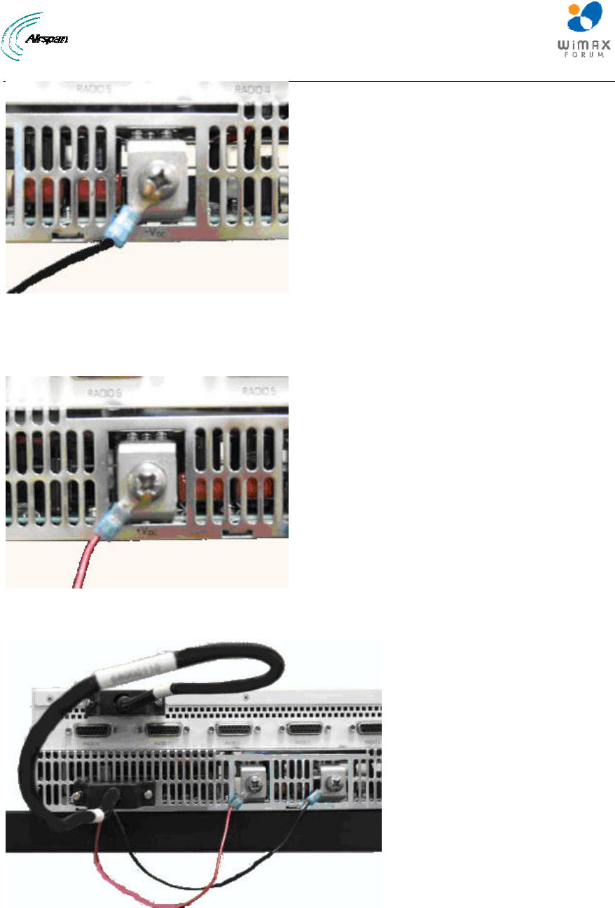
MicroMAX Hardware Installation User Guide
Page 75 Commercial in Confidence UWB-D00068 Rev J
Figure 65 - Connect to Negative
4. Connect the RED crimped wire from the 25-pin cable now to Port J1 on the back panel of the
AC/DC Convertor to the +VDC (Positive) output of the AC/DC Convertor on the back panel,
as shown below.
Figure 66 - Connect to Positive
5. Check the back panel of the BSDU and AC/DC Convertor appears as below:
Figure 67 - Back panels
6. Connect the power cable terminated with the Anderson Powerpole connectors to the -48V
input on the front panel of the BSDU, as shown below.
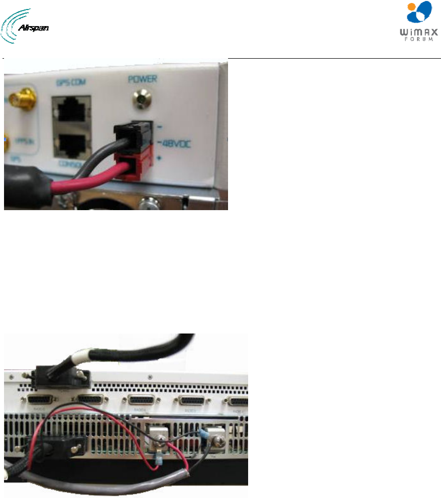
MicroMAX Hardware Installation User Guide
Page 76 Commercial in Confidence UWB-D00068 Rev J
Figure 68 - Front power connect
7. Connect the opposite ends of the cable to the DC output on the Rear Panel of the AC/DC
Convertor as follows:
a. The +VDC (Positive) output of the AC/DC converter is connected to the + Positive (Red)
input on the BSDU
b. The -VDC (NEGATIVE) output of the AC/DC converter is connected to the - Negative
(Black) input on the BSDU
The rear panels of the BSDU and AC/DC converter, shown below:
Figure 69 - Rear panels
8. Connect the AC/DC converter to AC Power and verify that:
a. On the AC/DC converter:
i. DC Supply module fans start up
ii. Green AC OK LED is lit
iii. DC OK LED is lit
b. On the BSDU:
i. All LEDs on the front panel are lit for several seconds
ii. The POWER LED on the front panel remains lit
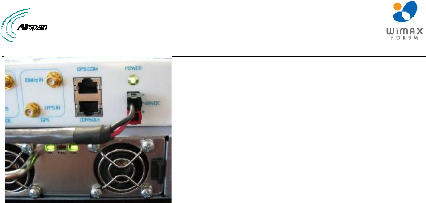
MicroMAX Hardware Installation User Guide
Page 77 Commercial in Confidence UWB-D00068 Rev J
Figure 70 - Front LEDs

MicroMAX Hardware Installation User Guide
Page 78 Commercial in Confidence UWB-D00068 Rev J
17 Lightning and Surge Protection
This section provides information for the installation of an effective grounding and suppression
system for the protection of products against lightning.
Different levels of protection should be decided jointly with customer according to:
¾ Geographical location / topographical conditions
¾ Environmental conditions
¾ Required level of availability
• Emergency Services
• Commercial – based on SLA
• Private use – based on SLA
¾ Cost factors
Level 1
¾ SFTP CAT-5e outdoor cable with proper grounding at both ends
Level 2
¾ SFTP CAT-5e outdoor cable proper grounding at both ends (Level 1)
¾ 1 Lightning/Surge Protector on CAT-5e outdoor cable on BSDU/SDA end
Level 3
¾ SFTP CAT-5e outdoor cable proper grounding at both ends (Level 1)
¾ 1 Lightning/Surge Protector on CAT-5e outdoor cable on BSDU/SDA end (Level 2)
¾ Additional Lightning/Surge Protector on BSR end
Table 27 - Level of Lightning Protection
Level of
Protection Flash density * Equipment placement
** Installation accessibility
*** Landscape
1 Low Less than 50m Good Plane
2 Low More than 50m Good Plane
3 Low - Poor Plane
2 Medium Less than 50m Good Plane
2 Medium More than 50m Good Plane
3 Medium - Poor Plane
3 High - - Plane
1 Low Less than 50m Good Hilly
2 Low More than 50m Good Hilly
3 Low - Poor Hilly
2 Medium Less than 50m Good Hilly
2 Medium More than 50m Good Hilly
3 Medium - Poor Hilly
MicroMAX Hardware Installation User Guide
Page 79 Commercial in Confidence UWB-D00068 Rev J
Level of
Protection Flash density * Equipment placement
** Installation accessibility
*** Landscape
3 High - - Hilly
2 Low - Good Mountainous
3 Low - Poor Mountainous
3 Medium - - Mountainous
3 High - - Mountainous
* Density (strikes per kilometer square per year)
o Low = Less than 5
o Medium = 5 – 14
o High = more than 14
** Relative to ground level
*** Accessibility – cost/time affects replacement considerations
Recommended good practices:
¾ Air-terminal and grounded mast/tower.
¾ Proper Bonding
¾ Proper Grounding
17.1 Lightning Protection
This is to describe the known mitigation defenses in general terms for application to
telecommunications facilities. A hierarchy of recognized application methods should be applied
according to site realities. This matrix is depicted below:
Table 28 - Application matrix
Exterior locationInterior LocationPeople SafetyStructure Safety
Air Terminals Yes No No Yes
Down Conductors Yes Yes No Yes
Bonding Yes Yes Yes Yes
Grounding Yes Yes Yes Yes
Surge Protection Yes Yes Yes Yes
17.1.1 Air Terminals
Lightning usually terminates on grounded objects sticking up in the air. This part of a lightning
protection system (LPS) is based upon the principles of Path of Least Impedance. On telecom
towers, ordinary sacrificial rods can protect sensitive antennae. In the main, the tower is the air
terminal. the height (“H”) of the Air Terminal tip above the highest element on the tower or pole,
typically the antenna, must be at least twice the distance (“2 x d”) between the outer surface of
the antenna and the tower or pole. This will ensure a "protection cone" of 45º around the tower or
pole. In areas of high lightning activity, the length (“H”) should be increased to up to 5 times the
distance. The Down Conductor must be installed straight and vertically in order to provide the
shortest and most direct path to earth. The formation of bends must be avoided.
We recommend that the Down-Conductor be at least 50 mm2 or AWG 0 in all cases.
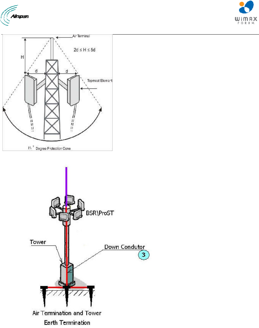
MicroMAX Hardware Installation User Guide
Page 80 Commercial in Confidence UWB-D00068 Rev J
Figure 71 - Air Terminal
Figure 72 - Termination and Tower
17.1.2 Grounding
Low-resistance grounding provides an efficient destination for the "lightning." If the site soils are
composed of sand or rock, they are resistive, not conductive. If the surrounding soils are clays or
dirt with moisture present, they likely are conductive. "Good Grounds" are achieved by volumetric
efficiencies. We recommend buried bare 4/0 copper wire – the so-called ring electrode or ring.
The grounding of the Down Conductor to earth must be of ground resistance no higher than 5 Ω.
This is achieved by using Earth Terminations and wherever possible, grounding to the steel re-
enforcement bars of the concrete base of the tower. This constitutes a part of the safety network
adapted to the electricity laws of the country, the terrain conditions, and the accepted and relevant
standards for the country.

MicroMAX Hardware Installation User Guide
Page 81 Commercial in Confidence UWB-D00068 Rev J
Note: The Grounding system must be maintained and checked periodically in
accordance with local regulations.
The Interconnecting cables shall be acceptable for external use and shall be
rated for proper application with respect to voltage, current, anticipated
temperature, flammability, and mechanical serviceability.
Hazardous network voltages are present in LAN ports regardless of whether
power to the unit is ON or OFF. To avoid electric shock , use caution when
near LAN ports. When detaching the cables, detach the end away from the
device first.
Do not work on the system or connect or disconnect cables during period of
lightning activity.
17.1.3 Surge Suppression
Surge suppression devices (LPS’s aka TVSS) all function either by absorbing the transient as
heat or forcing the transient to ground (or some combination thereof). Data line building entry
points for critical electronic equipment. Included here is Catting 5 lines, and twin lead and other
copper wire circuits.
The Lightning Protection architecture is considered, as follows:
¾ Subscriber Indoor Units connected to outdoor antennas. System, where Indoor/Outdoor
connections are via shielded CAT-5e cables that carry the baseband signals and a DC
supply voltage.
¾ The Lightning Protection System comprises grounding methods and Transient
suppression techniques (TVS).
Airspan products contain embedded Lightning Protectors at all their input ports. If additional
protection is required, for example, in high lightning activity areas, external Lightning Protectors
should be installed at strategic points at the site.
The CAT-5e shielded outdoor cable consists of twisted pair wires for Ethernet data, pair of wires
for the DC supply and pair of wires for sync. The Cable connects to the indoor unit via a grounded
Lightning Protection Box. The Lightning Protection Box is connected to an Earth Termination via a
Down-Conductor.
General Installation
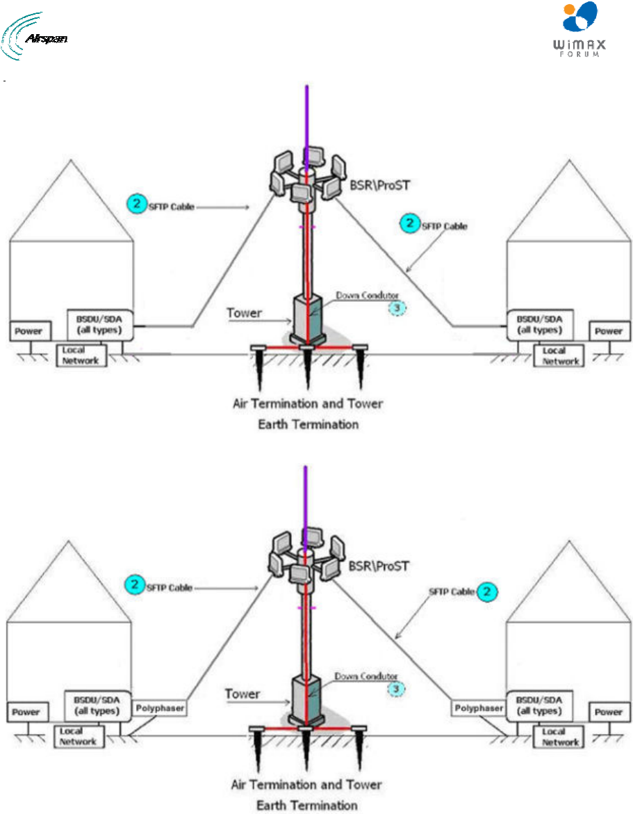
MicroMAX Hardware Installation User Guide
Page 82 Commercial in Confidence UWB-D00068 Rev J
Figure 73 - Level 1
Figure 74 - Level 2
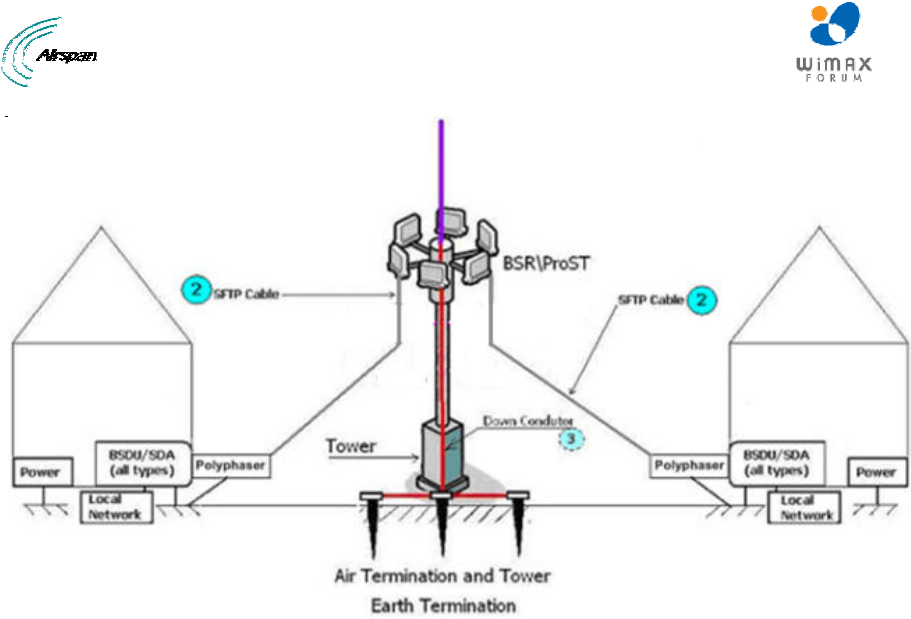
MicroMAX Hardware Installation User Guide
Page 83 Commercial in Confidence UWB-D00068 Rev J
Figure 75 - Level 3

MicroMAX Hardware Installation User Guide
Page 84 Commercial in Confidence UWB-D00068 Rev J
Table 29 – Accessories
Item
No. Description Manufacturer Manufacturer
P/N QuantityRemark
1 Copper wire 0
AWG
N/A N/A N/A Ground resistance must
be less than 1 Ohm.
UL approved cable
2 CAT-5e SFTP with
drain and double
jacket
N/A N/A N/A Up to 100 meters
3 Bare Copper Wire
4/0 AWG
N/A N/A N/A Ground resistance must
be less than 5 Ohm.
UL approved cable
Ring terminal N/A N/A N/A Stud H (1/4), Diameter
matching the used
Copper Wire diameter.
Circuit Lightning
protection for BSR
Polyphaser IX
series
IX-
2H1L1DC48-
IG
1 Installed with BSR
Circuit Lightning
protection for
ProST
Polyphaser IX
series
IX-2H1DC48-
IG
1 Installed with ProST
17.2 Cable Preparation (for grounding)
The CAT-5e SFTP cable is supplied unassembled. Therefore, you need to crimp the drain wire to
the ring terminal and paired wires to the connector's contact pins.
Required:
¾ CAT-5e SFTP cable
¾ Ring terminal and red insulation boot
¾ Crimping tool
To crimp the CAT-5e SFTP “drain” wire to the ring terminal:
1. Carefully strip the insulation from the SFTP cable (5 – 10cm).
Caution: Do not damage the insulation of the inner twisted pair wires.
2. Peel back the foil from around the wires.
3. Isolate the “drain” (ground) wire.
4. Crimp the ring terminal to the drain wire. Insert the wire into the ring terminal’s barrel, and
then, with a standard crimping tool crimp the barrel tightly onto the wire. Fold back the drain
wire with the ring terminal attached.
5. Strip the ends of the paired wires according to the connector.
6. Connect ground wire (with extension if required) to the tower.
The figures and connections are displayed below:
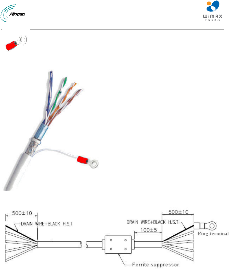
MicroMAX Hardware Installation User Guide
Page 85 Commercial in Confidence UWB-D00068 Rev J
Figure 76 - Ring terminal
Figure 77 – CAT-5e SFTP cable with ring terminal
Figure 78 - Complete assembly with Ferrite (optional)
17.3 FM Interference & ESD Protection Recommendations
When FM Interference is a factor:
¾ Ferrite suppressor (displayed in figure above) on the CAT-5e cable, near BSR
¾ Loop the CAT-5e cable on the BSR end
When ESD is an issue:
¾ Verify that the CAT-5e SFTP cable properly grounded at both ends
17.4 Connecting Lightning and Surge Protector
The optional third-party lightning and surge protector (Polyphaser) is implemented in the following
deployment scenarios:
¾ ODU-to-IDU cable length of 40 meters or more (mandatory to use surge protector)
MicroMAX Hardware Installation User Guide
Page 86 Commercial in Confidence UWB-D00068 Rev J
¾ Deployment of MicroMAX in geographical areas that frequently experience severe
lightning storms
The lightning and surge protector protects the ODU-to-IDU CAT-5e cable's six or eight
(depending on configuration) (for GPS synchronization all 8 CAT-5e wires are used) used wires
(two -48 VDC wires and four Ethernet Tx and Rx wires) from any electrical surges due to lighting
strikes.
The protector is installed outdoors on the CA-5e cable that connects between the MicroMAX and
the SDA-4S Type II (ODU). In other words, two CAT-5e cables are required for the following
connections:
¾ MicroMAX-to-protector connection
¾ Protector-to-IDU connection
Caution: Do not install the lightning and surge protector during adverse
weather conditions when the threat of lightning strike is possible.
Note: The protector unit must be grounded to a low-impedance (low R and
low L) ground system to operate properly.
Note: For pricing and ordering of the Polyphaser lightning and surge
protector, contact your Airspan representative.
To install the lightning protector:
1. Connect the protector in the direction according to the labels. The end labeled SURGE
accepts the cable from the MicroMAX; the end labeled PROTECTED accepts the cable from
the SDA-4S, or BSDU.
2. Feed the CAT-5e cable through the grommet (for each side). If the RJ-45 connector is
already crimped to the other end, ensure that you have fed the cable through the gland nut
beforehand. The gland nut secures the cable to the grommet.
3. Strip about 0.25" (6.35 mm) of the cable sheath and expose about 0.03" (0.8 mm) of the
strands/wires.
4. Secure the wires to the protector's terminal block using the two spot ties. Each side of the
data and DC assembly has + or – markings to ensure lines entering (surge side) match lines
exiting (protected side).
Note: Polyphaser should be installed close to the units but only externally.
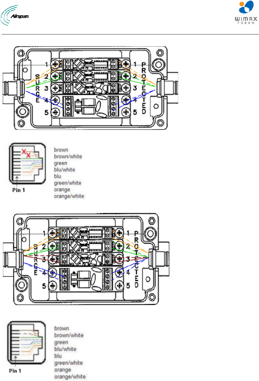
MicroMAX Hardware Installation User Guide
Page 87 Commercial in Confidence UWB-D00068 Rev J
Polyphaser Wiring Diagrams
Figure 79 - Working with SDA (W/O GPS Sync)
Figure 80 - RJ45 working with SDA
Figure 81 - Working with BSDU (GPS Sync)
Figure 82 - RJ45 working with BSDU
5. Mount and ground the protector -s with the provided 2 x 8-32 screws according to the
template illustrated below (showing distances between centers of the two mounting holes).
The unit may be mounted/grounded on a nearby plate or bulkhead panel that is bonded to
an earth-ground system.
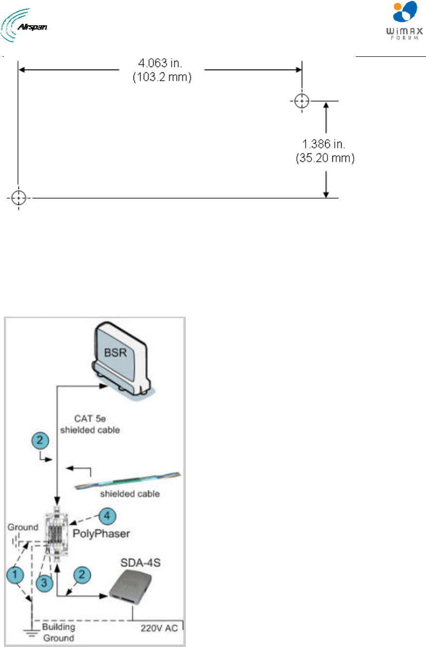
MicroMAX Hardware Installation User Guide
Page 88 Commercial in Confidence UWB-D00068 Rev J
Figure 83 - Mounting template
6. Attach the protector's lid by using the four M4 x 20-mm screws. Ensure that the neoprene
gasket on the lid is not loose or out of the groove.
7. Secure the CAT-5e cable to the grommet by fastening the gland nut.
17.5 Lightning and Surge Protection Connection Scenarios
The figures below illustrate various lightning and surge protector connectivity scenarios.
Figure 84 - SDA-4S + Polyphaser + BSR
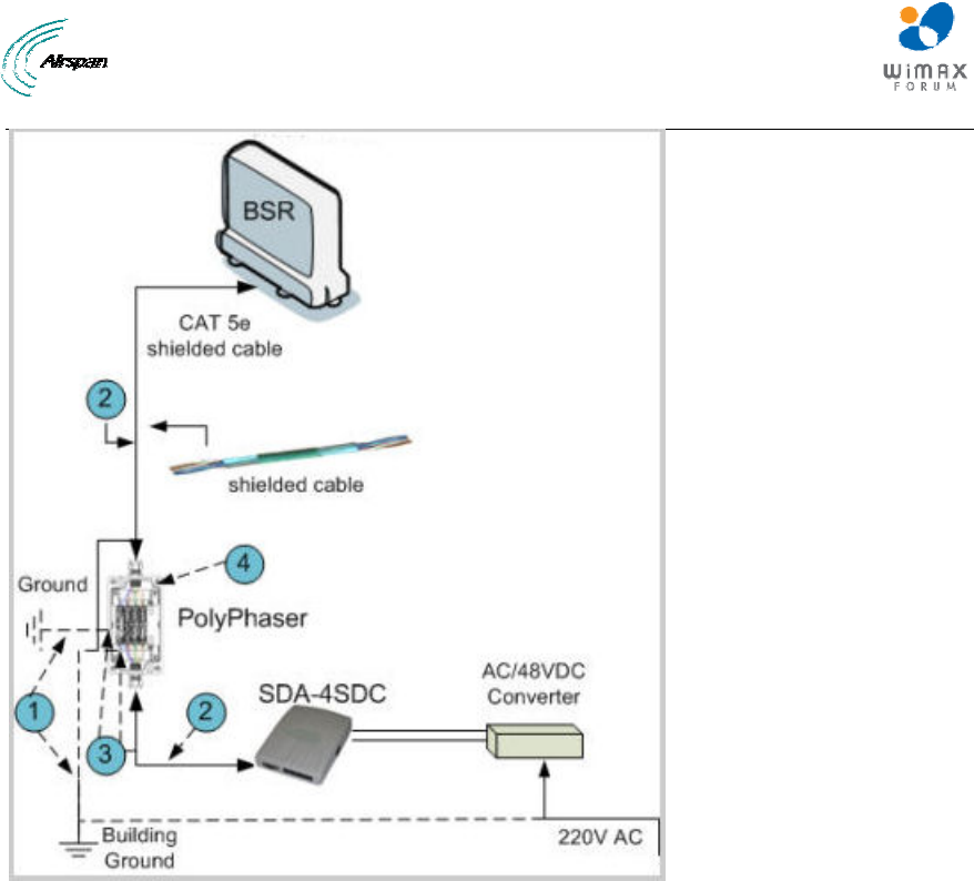
MicroMAX Hardware Installation User Guide
Page 89 Commercial in Confidence UWB-D00068 Rev J
Figure 85 - SDA-4SDC + Polyphaser + BSR
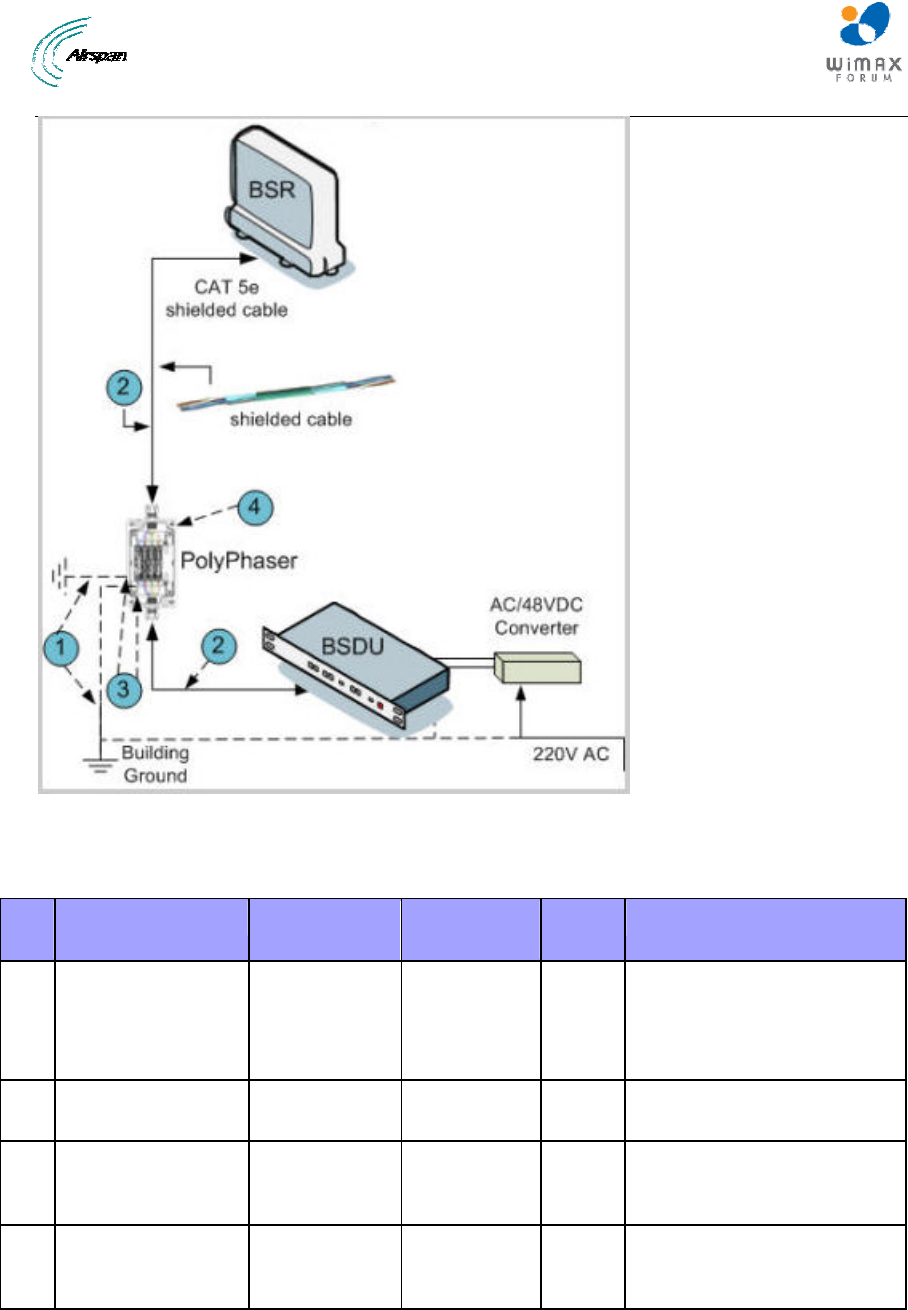
MicroMAX Hardware Installation User Guide
Page 90 Commercial in Confidence UWB-D00068 Rev J
Figure 86 - BSDU + Polyphaser + BSR
The following table describes the connections:
Table 30 - Description
Item
# Description Manufacturer Manufacture
P/N QuantityComment
1 Copper wire 0 AWG N/A N/A N/A Ground resistance must be
less than 5 Ohm.
Cable should have UL
approval.
2 SFTP Cat-5E
Shielded
N/A N/A N/A up to 100 meters in length
3 Ring terminal N/A N/A N/A Stud H (1/4), Diameter to
match the copper wire
diameter used
4 Circuit Lightning
protection for BSR
Polyphaser IX
series
IX-
2H1L1DC48-
IG
1 Installed with BSR
MicroMAX Hardware Installation User Guide
Page 91 Commercial in Confidence UWB-D00068 Rev J
18 Connecting Third-Party External Antennas
This section describes the procedures for connecting third-party external radio and Global
Positioning System (GPS) antennas to the BSR and BSDU, respectively. The implementation of
these antennas depends on the BSR model (with respect to radio antennas) and the need for
synchronization of the system (with respect to GPS antennas).
The MicroMAX BSR model without a built-in antenna provides an N-type port for connecting a
third-party external antenna. The addition of an external antenna allows greater RF sector
coverage than the standard MicroMAX BSR built-in antenna model.
Caution: Before connecting the external antenna, ensure that the MicroMAX
is not connected to the power source.
Caution: Before powering on the MicroMAX, ensure that some type of
equipment such as an antenna or an RF attenuator is connected to the N-
type receptacle. This eliminates the risk of irreversibly damaging the
MicroMAX device.
Caution: It is the responsibility of the person installing the MicroMAX to
ensure that only those antennas certified with the product are used. The use
of any antenna other than those certified with the product is expressly
forbidden.
Caution: The external antenna must not be co-located or operating in
conjunction with any other antenna or transmitter.
Caution: The MicroMAX and external antenna should be installed ONLY by
experienced installation professionals who are familiar with the local building
and safety codes and are licensed by the appropriate government authorities.
Note: The MicroMAX model that provides an N-type connector for attaching a
third-party external antenna does not contain an internal, built-in antenna.
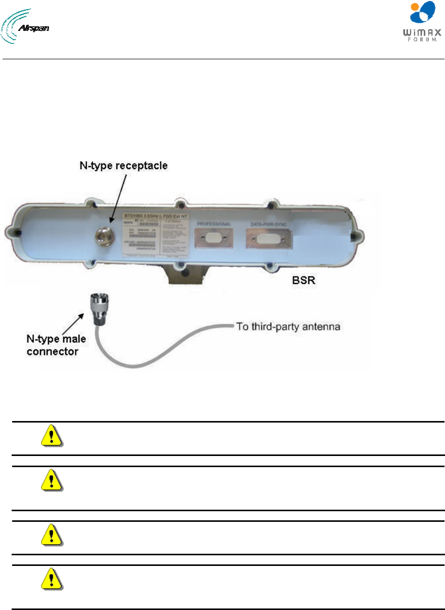
MicroMAX Hardware Installation User Guide
Page 92 Commercial in Confidence UWB-D00068 Rev J
The following lists the cable setup for attaching the external antenna:
¾ Cable: RF coaxial
¾ Connector: N-type male
To connect a third-party external antenna to the MicroMAX:
¾ Connect the N-type male connector of the third-party antenna to the N-type receptacle
located on the MicroMAX's panel (labeled ANTENNA), as displayed below.
Figure 87 - Antenna connection
18.1 Connecting GPS Antenna to BSDU
Caution: To avoid electrical or fire hazard, ensure that the connection to the
GPS is made prior to connecting the BSDU to the power supply.
Caution: A primary lightning protection device must be provided by the
operator/customer as part of an extra-building installation to ensure transient
voltage levels of less than 600 V maximum.
Caution: Changes or modifications to this equipment not expressly approved
by Airspan Networks Inc. could result in violation of Part 15 of the FCC rules.
Caution: This is a Class B product. In a domestic environment this product
may cause radio interference in which case the user may be required to take
adequate measures to correct the interference.
18.1.1 Connecting the GPS
The GPS antenna connects to the BSDU's 15-pin D-type port, labeled GPS, located on the
BSDU's rear panel, as shown below. The connection to the GPS is made through a 12-pin RS-
422 serial interface port that provides both communication and power interfaces.
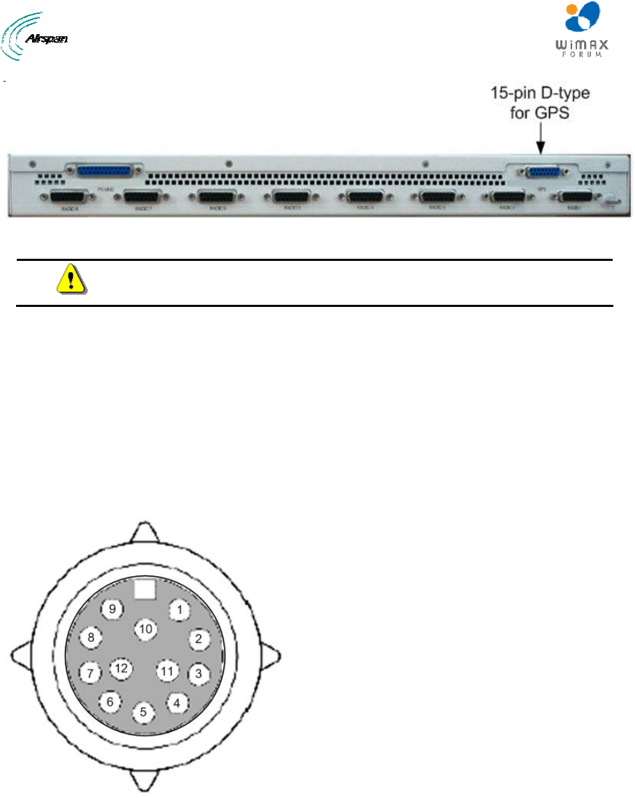
MicroMAX Hardware Installation User Guide
Page 93 Commercial in Confidence UWB-D00068 Rev J
Figure 88 - BSDU rear panel GPS port
Caution: To avoid electrical or fire hazard, ensure that the connection to the
GPS is made prior to connecting the BSDU to the power supply.
The GPS-to-BSDU cable setup is as follows:
¾ Cable: 12-pin conductor cable for RS-422 serial interface (multipair overall shielded -- 22
AWG) of 5, 15, or 30 meters in length depending on customer requirements (100 meter
maximum length)
¾ Connectors:
• GPS side: RS-422 weathertight 12-pin plug (Deutsch MMP26C-2212S1)
• BSDU side: 15-pin D-type male
• Connector pinouts: The GPS connector receptacle contains 12 male contacts, as
displayed below:
Figure 89 - GPS connector pinouts

MicroMAX Hardware Installation User Guide
Page 94 Commercial in Confidence UWB-D00068 Rev J
The connector pinouts for the GPS-to-BSDU 12-pin cabling are described in the table below.
Table 31 - Connector pinouts for BSDU-to-GPS cabling
Multipair overall shielded (22 AWG) cable
GPS BSDU
12-pin female 15-pin D-type male
Pin Pin
1 13
2 6
3 5
4 4
5 3
6(NC) x
7(NC) x
8(NC) x
9 12
10 x
11 7
12 8
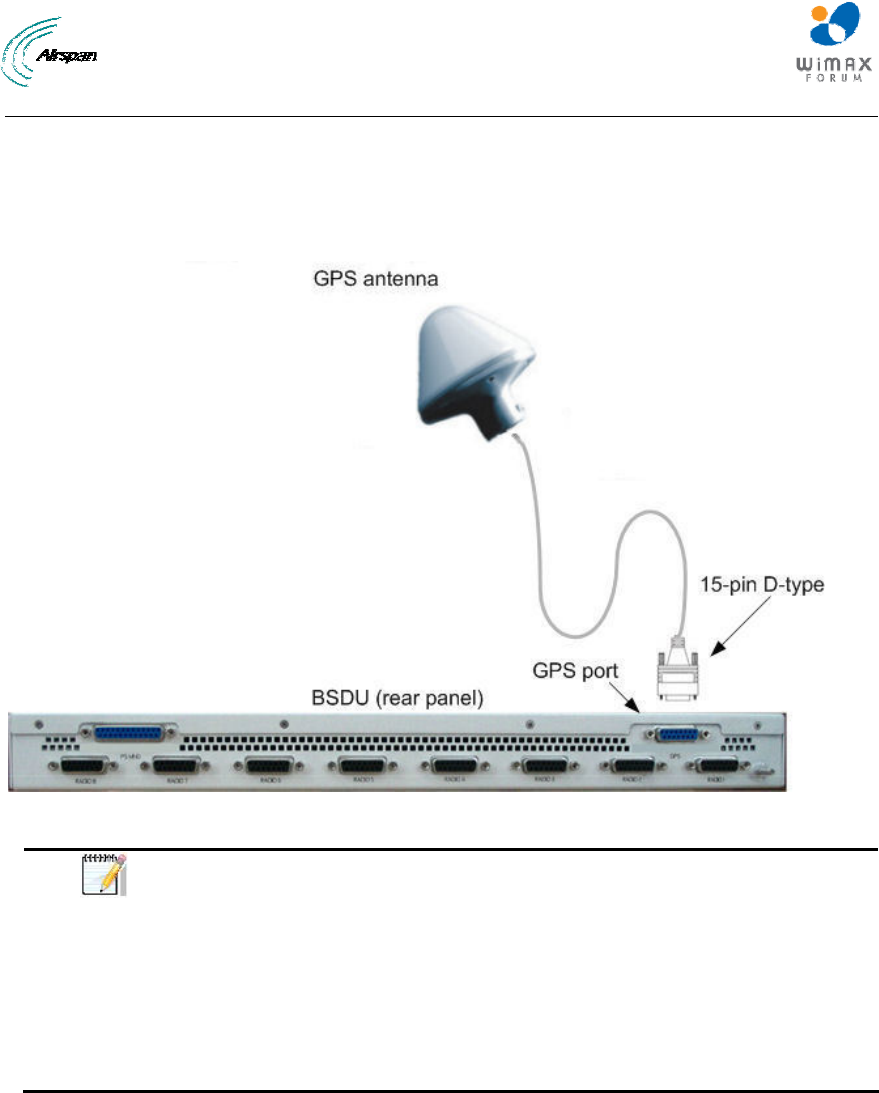
MicroMAX Hardware Installation User Guide
Page 95 Commercial in Confidence UWB-D00068 Rev J
To connect the GPS antenna to the BSDU:
1. Connect the 12-pin female connector, at one end of the cable, to the 12-pin receptacle
located on the underside of the GPS.
2. Connect the 15-pin D-type male connector, at the other end of the cable, to the 15-pin D-
type port labeled GPS located on the rear panel of the BSDU.
Figure 90 - GPS-to-BSDU cable connection
Note:
• When installing the cable, secure the cable to the mounting
pole or bracket with a cable tie to hold the weight of the cable
(i.e. cable strain relief).
• A loop should be left in the dressed cable for maintenance
purposes and to prevent the cable weight being taken
directly on the connector itself.
• Ensure that the connector is waterproof.
18.1.2 GPS Alignment
Many GPS reception problems can be reduced, to some degree, by careful antenna site
selection.
¾ Place the GPS so that unobstructed line-of-sight reception is possible from horizon to
horizon and at all bearings and elevation angles from the antenna. This is the ideal
situation, which may not be possible under actual operating conditions.
¾ Try to place the GPS as far as possible from reflective objects, especially reflective
objects that are above its radiation pattern horizon. Close-in reflections cause strong
multipath signals.
¾ Care should also be taken to avoid coiling the GPS cable around the mounting base and
pinching the cable in windows or doors.
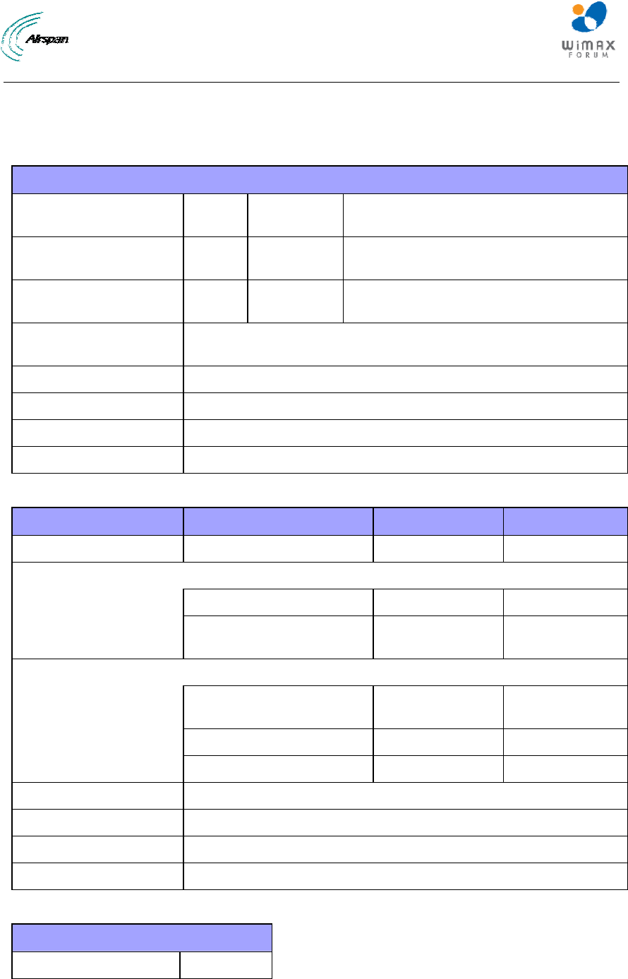
MicroMAX Hardware Installation User Guide
Page 96 Commercial in Confidence UWB-D00068 Rev J
19 Appendix
19.1 Environmental
Table 32 - BSR & SDA
Environmental
ETS 300 019-1-1 19
92
Class
1.2
Environmental conditions: storage
ETS 300 019-1-2 19
92
Class
2.3
Environmental conditions: transport
ETS 019-1-3 19
92
Class
3.2
Environmental conditions: stationary
weather-protected
Operating Temperature -33° to +55° C for outdoor MicroMAX BSR
0 to +40° C for indoor SDA
Humidity 95% @ 40° C (non condensing)
Storage Temperatures -40 to 70° C ambient
EMC ETS EN 301 489-4
Safety IEC60950-1, EN60950-1, UL60950-1
Table 33 – BSDU
Environmental
ETS 3000 019 ETSI
EMC
EN 300 386-2 ETSII
FCC 47CFR 15
sub B
FCC
Safety
Underwriters
Laboratories (UL)
1950 USA
IEC 60950 International
EN 60950 ETSI
Operating temperature 0-50° C ambient
Storage temperature -40 to 70° C ambient
Operating Humidity 15-90% RH
Storage Humidity 5-95% RH
Table 34 - GPSD
Environmental
Operating Temperature 0 to +40° C

MicroMAX Hardware Installation User Guide
Page 97 Commercial in Confidence UWB-D00068 Rev J
19.2 Glossary of Terms
AAS Adaptive antenna system (see Introduction for further details)
AP Access point
API Application programmers interface
ATCA Advanced telecommunications computing architecture
BE Best effort scheduling service for requesting uplink bandwidth
BER Bit error rate
BS Base station
BSDU Base Station Distribution Unit
BSR Base Station Radio
BWA Broadband wireless access
CIR Committed information rate used to specify the guaranteed data rate
to the customer.
CPE Customer premises equipment (interchangeable with ST)
DCD Downlink channel descriptor
DL Downlink
DLFP Downlink frame prefix
E1 ITU term for a 2Mb/s pulse code modulated transmission link
EiRP Effective isotropic radiated power
FCH Frame control header
FDD Frequency division duplex
FEC Forward error correction
FFT Fast Fourier transform used to convert a signal from the time domain
into the frequency domain
H-FDD Half duplex FDD
IAD Integrated access device
IP Internet protocol
Kb/s Kilobits per second
MAC The next layer up from the PHY, known as the media access
controller
Mb/s Megabits per second
MIB Management interface block
MIMO Multiple-in, multiple-out
MIR Maximum information rate used to specify the maximum data
throughput to a customer.
MRC Maximal-ratio combining
NPI New Product Introduction
NLOS None line of sight radio propagation path

MicroMAX Hardware Installation User Guide
Page 98 Commercial in Confidence UWB-D00068 Rev J
NRTP Non real time polling is similar to real time polling but is used to
request uplink bandwidth less regularly
O&M Operations and maintenance
ODU Outdoor unit associated with a ST
OFDM Orthogonal frequency division multiplexing
PHY The physical layer associated with the WiMAX interconnection stack
PMP Point to multipoint radio systems architecture
PoE Point to point protocol over Ethernet
PtP Point to point radio systems architecture
QoS Quality of service, which is used to specify level of data throughput
REC Radio equipment controller
RTP Real time polling allows a service flow to request uplink bandwidth at
regular intervals
Rx Receiver
SDMA Space division multiple access is a technique which makes it
possible to increase the capacity of a cellular mobile radio system by
taking advantage of spatial separation between users
SDR Software defined radio
SF Service flow
SFTP Shielded Foiled Twisted Pair (cable type)
SME Small to medium sized enterprise
SNMP Simple network management protocol
SNR Signal to noise
SOFDMA Scalable orthogonal frequency division multiplexing
SoHo Small office/home office
SS Subscriber station (interchangeable with CPE or ST)
ST Subscriber terminal (interchangeable with CPE or SS)
STC Space time coding
T1 North American standard 1.56Mb/s pulse code modulated
transmission link
TDD Time division duplex
TDM Time division multiplexing
Tx Transmitter
UCD Uplink channel descriptor
UGS Unsolicited grant service used to provide fixed bandwidth slots on the
uplink for an ST to transmit data at regular intervals. The bandwidth
should be used by the UGS SF, however the final decision of which
SF (if any) uses the bandwidth slot is made by the ST.
VoIP Voice over Internet protocol

MicroMAX Hardware Installation User Guide
Page 99 Commercial in Confidence UWB-D00068 Rev J
WiMAX WiMAX is a wireless industry coalition whose members are
organized to advance IEEE 802.16 standards for broadband wireless
access (BWA) networks.

MicroMAX Hardware Installation User Guide
Page 100 Commercial in Confidence UWB-D00068 Rev J
19.3 Revision History
Revision Originator Date Description
Rev A M. Falik 5-2006 Initial document
Rev B M. Falik 6-2006 additional content
Rev C M. Falik 6-2006 corrections
Rev D M. Falik 9-2006 added Polyphaser
Rev E M. Falik 10-2006 Added SDA-4SDC
Rev F M. Falik 4-2007 Added BSDU and
GPS
Rev G M. Falik 10-2007 Added Polyphaser
Info + charts
Rev H M. Falik 2-2008 Additions
Rev I M. Falik 7-2008 Template change +
updates
Rev J M. Falik 2-2009 Additions +
corrections
19.4 Contact Information
Customer Service Help-Desk for customer service emergency
Airspan Networks have introduced the Airspan Tracker application to enable prompt and efficient
Customer Support services.
If you do not have an Airspan Tracker account, please obtain login credentials by filling-in the form in
the main page "Register New Account".
Worldwide Headquarters:
Airspan Networks Inc.
777, Yamato Road, Suite 105,
Boca Raton, FL 3341-4408, USA
Tel: +1 561 893 8670
www.airspan.com
Feedback:
To provide feedback on this document, please send comments to the following email address:
www.airspan.com