Airspan Networks MRT4900 WiMAX MRT CPE User Manual Rev
Airspan Networks Inc WiMAX MRT CPE Rev
User Manual Rev

Airstream 4001 F49-MRT User
Guide

Airstream 4001 F49-MRT User Guide
Page 2 Commercial in Confidence UWB-D00211 Rev B
Acknowledgements
Airspan Networks Inc acknowledges the following trademarks used within this document:
© Microsoft Corporation http://www.microsoft.com
Copyright
© Copyright by Airspan Networks Inc., 2013. All rights reserved worldwide.
The information contained within this document is proprietary and is subject to all relevant copyright,
patent and other laws protecting intellectual property, as well as any specific agreements protecting
Airspan Networks Inc. rights in the aforesaid information. Neither this document nor the information
contained herein may be published, reproduced or disclosed to third parties, in whole or in part,
without the express, prior, written permission of Airspan Networks Inc. In addition, any use of this
document or the information contained herein for the purposes other than those for which it is
disclosed is strictly forbidden.
Airspan Networks Inc. reserves the right, without prior notice or liability, to make changes in
equipment design or specifications.
Information supplied by Airspan Networks Inc. is believed to be accurate and reliable. However, no
responsibility is assumed by Airspan Networks Inc. for the use thereof nor for the rights of third parties
which may be effected in any way by the use of thereof.
Any representation(s) in this document concerning performance of Airspan Networks Inc. product(s)
are for informational purposes only and are not warranties of future performance, either expressed or
implied. Airspan Networks Inc. standard limited warranty, stated in its sales contract or order
confirmation form, is the only warranty offered by Airspan Networks Inc. in relation thereto.
This document may contain flaws, omissions or typesetting errors; no warranty is granted nor liability
assumed in relation thereto unless specifically undertaken in Airspan Networks Inc. sales contract or
order confirmation. Information contained herein is periodically updated and changes will be
incorporated into subsequent editions. If you have encountered an error, please notify Airspan
Networks Inc. All specifications are subject to change without prior notice.
Product performance figures quoted within this document are indicative and for information purposes
only.
Safety Notices
Safety Information
1. Read this user manual and follow all operating and safety instructions.
2. Keep all product information for future reference.
3. The power requirements are indicated on the product-marking label. Do not exceed the
described limits.
4. Use only a damp cloth for cleaning. Do not use liquid or aerosol cleaners.
Disconnect the power before cleaning.
5. Disconnect power when unit is stored for long periods.

Airstream 4001 F49-MRT User Guide
Page 3 Commercial in Confidence UWB-D00211 Rev B
Table of Contents
Acknowledgements .......................................................................................................................... 2
Copyright .......................................................................................................................................... 2
Safety Notices ................................................................................................................................... 2
Safety Information ......................................................................................................................... 2
Table of Contents ............................................................................................................................. 3
Summary of Figures ......................................................................................................................... 6
Summary of Tables .......................................................................................................................... 7
Warnings and Cautions .................................................................................................................... 8
Human Exposure to Radio Frequencies....................................................................................... 8
Radio Interference ........................................................................................................................ 8
Modifications ................................................................................................................................. 8
General ......................................................................................................................................... 8
Disclaimer Statement ................................................................................................................... 8
DECLARATION OF CONFORMITY ................................................................................................. 9
FCC Notice ..................................................................................................................................... 10
Federal Communication Commission Notice ............................................................................. 10
1About this Guide ....................................................................................................................... 11
1.1Purpose ................................................................................................................................. 11
1.2Conventions .......................................................................................................................... 11
2System Overview ..................................................................................................................... 12
2.1MRTe Frequency Ranges ..................................................................................................... 12
2.1.1Main Features ............................................................................................................... 12
2.2WiMAX Management ............................................................................................................ 12
2.3WiFi Management ................................................................................................................. 12
2.4Architecture ........................................................................................................................... 13
2.5Theory of Operation .............................................................................................................. 13
3Installation Prerequisites .......................................................................................................... 14
3.1Package Contents ................................................................................................................. 14
4Physical Description ................................................................................................................. 15
4.1MRTe ..................................................................................................................................... 15
4.1.1Physical Dimensions ..................................................................................................... 15
4.1.2Ports .............................................................................................................................. 15
4.1.3LED Display ................................................................................................................... 15
5Connections ............................................................................................................................. 16
5.1Power Supply Connector Pinout ........................................................................................... 16
5.2Ethernet Connection ............................................................................................................. 16
5.2.1Assemble Ethernet Connector ...................................................................................... 16

Airstream 4001 F49-MRT User Guide
Page 4 Commercial in Confidence UWB-D00211 Rev B
6Connecting WiMAX and WiFi Antennas .................................................................................. 17
7Mounting .................................................................................................................................. 18
7.1Mounting the MRTe ............................................................................................................... 18
8Network Cabling ....................................................................................................................... 19
8.1Connecting to Network .......................................................................................................... 19
9Connecting to Power ................................................................................................................ 20
10Initial Procedure for Web-Based Management ..................................................................... 21
10.1Browser Requirements .................................................................................................. 21
10.2System Configuration and Login ................................................................................... 21
10.2.1Accessing the Airstream 4001 F49-MRT ...................................................................... 21
10.3Navigating Your Airstream 4001 F49-MRT Management ............................................. 22
10.3.1Menus ............................................................................................................................ 22
10.3.2Navigating ..................................................................................................................... 23
11Status .................................................................................................................................... 24
11.1WiMAX Status ............................................................................................................... 24
11.2Network Status .............................................................................................................. 25
11.3Device Information ........................................................................................................ 26
12System .................................................................................................................................. 28
12.1Reboot ........................................................................................................................... 28
12.2Reset to Default ............................................................................................................. 29
12.3Software Download ....................................................................................................... 29
13WiMAX .................................................................................................................................. 32
13.1Scanning Setup ............................................................................................................. 32
13.1.1Channels ....................................................................................................................... 32
13.1.2Scanning Setup ............................................................................................................. 32
13.2Authentication ................................................................................................................ 33
13.2.1Authentication Status .................................................................................................... 33
14Network ................................................................................................................................. 35
14.1Mode (Router/Bridge) Configuration ............................................................................. 35
14.1.1Router Mode - WAN IP Address ................................................................................... 35
14.1.2Bridge Mode - WAN IP Address .................................................................................... 35
Examples: ................................................................................................................................ 36
14.1.3LAN IP Configuration .................................................................................................... 37
14.2DMZ ............................................................................................................................... 37
14.3WiFi ............................................................................................................................... 38
15Logout ................................................................................................................................... 39
16Reboot ................................................................................................................................... 40
17Appendix ............................................................................................................................... 41

Airstream 4001 F49-MRT User Guide
Page 5 Commercial in Confidence UWB-D00211 Rev B
17.1Glossary of Terms ......................................................................................................... 41
17.2Revision History ............................................................................................................ 43
17.3Contact Information ....................................................................................................... 43

Airstream 4001 F49-MRT User Guide
Page 6 Commercial in Confidence UWB-D00211 Rev B
Summary of Figures
Figure 1 - Airstream 4001 F49-MRT..................................................................... 错误!未定义书签。
Figure 2 - MRTe .................................................................................................... 错误!未定义书签。
Figure 3 - MRTe port panel .................................................................................. 错误!未定义书签。
Figure 4 - LED Display ......................................................................................... 错误!未定义书签。
Figure 5 - Power pins - power supply cable connector .................................................................. 16
Figure 6 - Gland assembly ............................................................................................................. 16
Figure 7 - Gland assembled ........................................................................................................... 16
Figure 8 - Mounting template .......................................................................................................... 18
Figure 9 - Login ............................................................................................................................... 22
Figure 10 - MRTe - Status .............................................................................................................. 22
Figure 11 - WiMAX Status .............................................................................................................. 24
Figure 12 - Network Status ............................................................................................................. 25
Figure 13 - Device Information ....................................................................................................... 26
Figure 14 - System Reboot ............................................................................................................. 28
Figure 15 - System Reboot progress.............................................................................................. 28
Figure 16 - System - Reset to Default ............................................................................................ 29
Figure 17 - System Software Download ......................................................................................... 30
Figure 18 - WiMAX - Scanner - Channels ...................................................................................... 32
Figure 19 - Scanning Setup ............................................................................................................ 32
Figure 20 - WiMAX - Authentication ............................................................................................... 33
Figure 21 - Networking - Bridge mode ........................................................................................... 35
Figure 22 - WAN DHCP .................................................................................................................. 36
Figure 23 - WAN Static IP Configurations ...................................................................................... 36
Figure 24 - WAN Static IP Mask Options ....................................................................................... 37
Figure 25 - LAN Static .................................................................................................................... 37
Figure 26 - DMZ.............................................................................................................................. 38
Figure 27 - WiFi .............................................................................................................................. 38
Figure 28 - Airstream 4001 F49-MRT - Reboot .............................................................................. 40

Airstream 4001 F49-MRT User Guide
Page 7 Commercial in Confidence UWB-D00211 Rev B
Summary of Tables
Table 1 - MRTe Frequency Ranges ............................................................................................... 12
Table 2 - Package Contents ........................................................................................................... 14
Table 3 - MRTe physical dimensions ............................................................................................. 15
Table 4 - MRTe port panel description ........................................................................................... 15
Table 5 - LED display description ......................................................................... 错误!未定义书签。
Table 6 -Power connector .............................................................................................................. 16
Table 7 - Airstream 4001 F49-MRT Menus .................................................................................... 23
Table 8 - Navigation ....................................................................................................................... 23
Table 9 - WiMAX Status with SF displayed .................................................................................... 24
Table 10 - Network status ............................................................................................................... 26
Table 11 - Device Information ........................................................................................................ 27
Table 12 - Software Download & Software Banks ......................................................................... 30

Airstream 4001 F49-MRT User Guide
Page 8 Commercial in Confidence UWB-D00211 Rev B
Warnings and Cautions
Human Exposure to Radio Frequencies
The WiMAX MRTe Antennas should be installed a minimum distance of 20 cm (8 in) from your
body.
Radio Interference
This equipment generates, uses, and can radiate radio frequency energy and, if not installed and
used in accordance with the instructions, may cause harmful interference to internal vehicle radio
communications.
Please ensure a maximum separation between the MRTe’s antenna and other antennas on the
roof of the vehicle.
Modifications
Any changes and modifications to this device that are not expressly approved by Airspan
Networks are not permitted and if done will result in voidance of warranty.
General
¾ Installation, replacement and service should be performed by qualified personnel who are
familiar with local safety codes.
¾ Do not mount external antennas in inclement weather (such as rain or lightning) that may
increase risk of electrocution.
¾ MRTe does not provide protection from hazard energy in case of single fault condition.
¾ Power supply shall be limited up to 3A in normal and single fault condition.
Disclaimer Statement
The information in this document is subject to change without notice and does not represent a
commitment on the part of the vendor. No warranty or representation, either expressed or implied,
is made with respect to the quality, accuracy or fitness for any particular purpose of this document.
The manufacturer reserves the right to make changes to the content of this document and/or the
products associated with it at any time without obligation to notify any person or organization of
such changes. In no event will the manufacturer be liable for direct, indirect, special, incidental or
consequential damages arising out of the use or inability to use this product or documentation,
even if advised of the possibility of such damages. This document contains materials protected by
copyright. All rights are reserved. No part of this manual may be reproduced or transmitted in any
form, by any means or for any purpose without expressed written consent of its authors. Product
names appearing in this document are mentioned for identification purchases only. All trademarks,
product names or brand names appearing in this document are registered property of their
respective owners.

Airstream 4001 F49-MRT User Guide
Page 9 Commercial in Confidence UWB-D00211 Rev B
DECLARATION OF CONFORMITY
European Community, Switzerland, Norway, Iceland, and Liechtenstein
Declaration of Conformity with Regard to the R&TTE Directive 1999/5/EC
English:
This equipment is in compliance with the essential requirements and other relevant provisions of
Directive 1999/5/EC.
Deutsch:
Dieses Gerät entspricht den grundlegenden Anforderungen und den weiteren entsprecheneden
Vorgaben der Richtlinie 1999/5/EU.
Dansk:
Dette udstyr er i overensstemmelse med de væsentlige krav og andre relevante bestemmelser i
Directiv 1999/5/EF.
Español:
Este equipo cumple con los requisitos esenciales asi como con otras disposiciones de la
Directive 1999/5/EC.
Greek:
ΜΕ ΤΗΝ ΠΑΡΟΥΣΑ Airspan ΔΗΛΩΝΕΙ ΟΤΙ Ο ΕΞΟΠΛΙΣΜΟΣ ΣΥΜΜΟΡΦΩΝΕΤΑΙ ΠΡΟΣ ΤΙΣ
ΟΥΣΙΩΔΕΙΣ ΑΠΑΙΤΗΣΕΙΣ ΚΑΙ ΤΙΣ ΛΟΙΠΕΣ ΣΧΕΤΙΚΕΣ ΔΙΑΤΑΞΕΙΣ ΤΗΣ ΟΔΗΓΙΑΣ 1999/5/ΕΚ.
Français:
Cet appareil est conforme aux exigencies essentialles et aux autres dispositions pertinantes de la
Directive 1999/5/EC.
Íslenska:
Þessi búnaður samrýmist lögboðnum kröfum og öðrum ákvæðum tilskipunar 1999/5/ESB.
Italiano:
Questo apparato é conforme ai requisiti essenziali ed agli altri principi sanciti dalla Direttiva
1999/5/EC.
Nederlands:
Deze apparatuur voldoet aan de belangrijkste eisen en andere voorzieningen van richtlijn
1999/5/EC.
Norsk:
Dette utstyret er i samsvar med de grunnleggende krav og andre relevante bestemmelser i EU-
directiv 1999/5/EC.
Português:
Este equipamento satisfaz os requisitos essenciais e outras provisões da Directiva 1999/5/EC.
Suomalainen:
Tämä laite täyttää direktiivin 1999/5/EY oleelliset vaatimukset ja on siinä asetettujen muidenkin
ehtojen mukainen.
Svenska:
Denna utrustning är i överensstämmelse med de väsentliga kraven och andra relevanta
bestämmelser i Direktiv 1999/5/EC.
Român:
Acest echipament este în conformitate cu cerinţele esenţiale şi alte prevederi relevante ale
Directivei 1999/5/CE.
The Declaration of Conformity related to this product can be obtained from
product_management@Airspan.com

Airstream 4001 F49-MRT User Guide
Page 10 Commercial in Confidence UWB-D00211 Rev B
FCC Notice
Federal Communication Commission Notice
This equipment has been tested and found to comply with the limits for a Class B digital device,
pursuant to part 15 of the FCC Rules. These limits are designed to provide reasonable protection
against harmful interference when the equipment is operated in a commercial environment. This
equipment generates, uses, and can radiate radio frequency energy and, if not installed and used
in accordance with the instruction manual, may cause harmful interference to radio
communications. Operation of this equipment in a residential area is likely to cause harmful
interference in which case the user will be required to correct the interference at his/her own
expense.
Fixed and base stations transmitting a signal with an emission bandwidth greater than 1 MHz
must not exceed an ERP of 1000 watts/MHz and an antenna height of 305 m HAAT, except that
antenna heights greater than 305 m HAAT are permitted if power levels are reduced below 1000
watts/MHz ERP.
This device complies with Part 15 of the FCC Rules. Operation is subject to the following two
conditions: (1) This device may not cause harmful interference, and (2) this device must accept
any interference received, including interference that may cause undesired operation.
FCC Caution: Any changes or modifications not expressly approved by the party responsible for
compliance could void the user's authority to operate this equipment.
Airstream 4001 F49-MRT User Guide
Page 11 Commercial in Confidence UWB-D00211 Rev B
1 About this Guide
This section discusses the purpose, intended audience, conventions, referenced documentation
and organization for this guide.
1.1 Purpose
The purpose of this User Guide is to provide step-by-step instructions for setting up and installing
the Airstream 4001 F49-MRT. These procedures include:
¾ System Overview
¾ Installation Prerequisites
¾ Physical description
¾ Mounting
¾ Cabling
¾ Connecting
¾ Initial Procedure for Web-based Management
1.2 Conventions
Icon Description
Checkpoint: Marks a point in the workflow where there may be an exit or
branch to some other procedure. At each Checkpoint the reason for an
exit or branch is given along with specific directions to locate the entry
point in the other procedure.
Reference: Gives a resource in the workflow that may be needed to
complete a procedure along with specific directions to use the resource.
Caution: Describes a possible risk and how to lessen or avoid the risk.
Advice: Provides a recommendation based on best practice.
Note: Provides useful information.

Airstream 4001 F49-MRT User Guide
Page 12 Commercial in Confidence UWB-D00211 Rev B
2 System Overview
MRTe (Mobile Ruggedized Terminal - 16e) is a ruggedized hybrid device integrating 16e WiMAX
CPE and WiFi Access Point functionalities in a single package. The MRTe was designed for
nomadic and vehicular operation, providing high-speed data access through its WiMAX and WiFi
interfaces.
MRTe is deployed with external vehicle mounted antennas for WiMAX and either directly
connected or external antennas for WiFi.
The WiMAX segment provides a wireless interface with the Airspan Mobile WiMAX base stations.
For WiFi interface with the customer's network, the MRTe is deployed with 2 RF connectors to
allow quick and easy attachment of the WiFi antennas. The MRTe provides 360-degree coverage
through its omni-directional antennas which are weatherproof, maintaining excellent antenna
performance in any weather.
MRTe’s interfaces can be managed by the Web-based management system using a standard
Web browser.
2.1 MRTe Frequency Ranges
The table below lists the frequency range of MRTe models currently available. This table will grow
as more models become available.
Table1‐MRTeFrequencyRanges
Frequency Band Channel Bandwidth
4950 - 4980 MHz TDD ¾ 10MHz
2.1.1 Main Features
The Airspan WiMAX MRTe provides the following main features:
¾ Ruggedized vehicular terminal based on the WiMAX IEEE 802.16e wireless technology.
¾ Vehicular configuration for in-car, truck or bus installation.
¾ Designed to meet severe environmental conditions:
• IP66 waterproof seal
• Shock - 30G (Per SAE-J1455, MIL-STD-202G, 213-1, Condition J)
• Vibration - 0.02PSD (Per SAE-J1455, MIL-STD-202G, Table 214-I, Condition A)
¾ IEEE 802.11n WiFi AP capabilities.
¾ Fed from vehicle 12V power supply.
2.2 WiMAX Management
¾ Supports Self Provisioning
¾ Hosts a web server for basic monitoring via a local browser
¾ Software is upgraded locally and remotely via FTP
¾ Local and remote management via NMS
¾ TR-069 - roadmap
2.3 WiFi Management
¾ Hosts a web server for basic monitoring via a WEB browser
¾ Software is upgraded locally and remotely via FTP

Airstream 4001 F49-MRT User Guide
Page 13 Commercial in Confidence UWB-D00211 Rev B
2.4 Architecture
The MRTe consists of the following components:
¾ Rugged hybrid device integrating WiMAX CPE and WiFi AP
¾ Weatherproof WIMAX antenna connectors (N type RF connector)
¾ Weatherproof WiFi antenna connectors (TNC connector)
See Package Contents for additional information.
2.5 Theory of Operation
For basic operation, the MRTe requires no initial configuration--simply plug and play.
Configuration is automatically performed over the air by the BS. The MRTe is preconfigured with
service flow parameters such as the maximum information rate, the committed information rate
and the maximum latency.
Airstream 4001 F49-MRT User Guide
Page 14 Commercial in Confidence UWB-D00211 Rev B
3 Installation Prerequisites
Before installing your MRTe, read the following to ensure that:
¾ No items are missing from the package
3.1 Package Contents
Examine the Airspan WiMAX MRTe shipping container. If you notice any damage, or missing
items as listed in the Packing List, immediately notify the carrier that delivered the unit and
contact an Airspan representative.
The MRTe kit should contain the following items:
¾ MRTe device
¾ Power cable
¾ Glands wrench
¾ Spare Fuse
Note: Antennas ordered separately. Contact supplier.
Note: Airspan does not provide screws, washer or nuts for mounting the
MRTe. The screw size depends on the structure of the cabinetry to which the
MRTe is to be attached. When selecting screw sizes, consideration must be
given to the weight and size of the MRTe and typical vibration conditions.
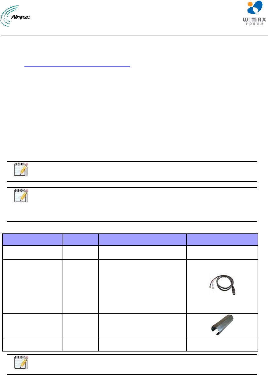
Table2‐PackageContents
Name Quantity Comments Image
MRTe 1
External Power
Cable
(PN: 687-00-050)
1
Terminated on MRTe power
connection with 2-pin screw-
down connector and Power
source side with 2 x #10 closed
end ring connectors.
White = (+)
Black = (-)
Glands Wrench 1 Tool for tightening the Glands.
Spare Fuse 1 Extra 6.3 A fuse.
Note: Additional parts are required e.g. antennas, RF cable all available from
Airspan. Please contact your supplier for additional information.
Airstream 4001 F49-MRT User Guide
Page 15 Commercial in Confidence UWB-D00211 Rev B
4 Physical Description
This section provides a description of the components of the MRTe installation:
¾ Dimensions
¾ Ports
¾ LEDs
4.1 MRTe
The MRTe is an encased outdoor radio providing access to communication ports on its side panel.
The MRTe provides holes for mounting.
4.1.1 Physical Dimensions
The table below lists the physical dimensions of the MRTe.
Table3‐MRTephysicaldimensions
Parameter Value
Dimensions (H x W x D) 59.5 x 172 x 204 mm (2.34 x 6.8 x 8.0 inches)
Weight 1.6 Kg (3.5 lbs.)
4.1.2 Ports
The MRTe provides the following ports on front panel.
Note: All ports come with protective covers for soil and damage protection.
Leave covers on for ports not in use. Store the covers for future use.
Table4‐MRTeportpaneldescription
Port Description
RF connection x 2 TNC RF external (WiFi) antenna connections
RJ-45 x 1 10/100/1000BaseT Ethernet LAN
Fuse 6.3A
DC power input
12V DC power connection (female)
Pin Description
1 “-”
2 “+“
RF connection x 2 - RS
type RF external (WiMAX) antenna connections
LEDs LEDs display (see description in the following
section)
4.1.3 LED Display
The LEDs are a visual display to indicate basic CPE status.:
Airstream 4001 F49-MRT User Guide
Page 16 Commercial in Confidence UWB-D00211 Rev B
5 Connections
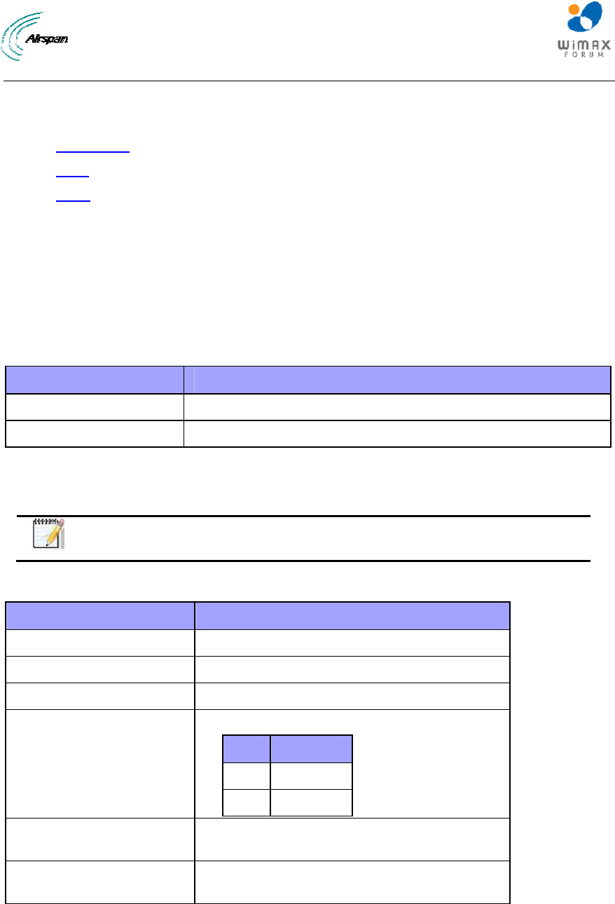
5.1 Power Supply Connector Pinout
The power supply connector provides 2-pin male contacts for cable connection. The connector is
attached to the power adapter cable.
Figure1‐Powerpins‐powersupplycableconnector
The connector’s pinout is described in the following table:
Table5‐Powerconnector
Power Description
1 “-” power in
2 “+“ power in
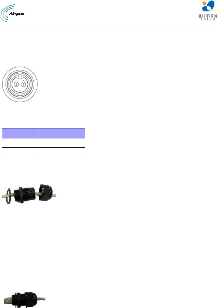
5.2 Ethernet Connection
The Ethernet cable is connected to the unit using a standard RJ45 connector protected by a
harsh environment protective casing.
Figure2‐Glandassembly
5.2.1 Assemble Ethernet Connector
1. Remove the connector by unscrewing the body from the unit, using the Gland wrench.
2. Pass the Cat 5e Ethernet cable through the tail nut, gland seal, body and rubber seal of the
connector casing as shown above. Do not tighten the tail nut.
3. Terminate the Ethernet cable with an RJ45 connector plug using an RJ45 crimping tool
unless it is pre-assembled.
4. Connect the terminated RJ45 cable to the female RJ45 outlet inside the unit.
5. Screw the RJ45 gland connector plug securely into the body cavity of the unit using the
provided Gland wrench.
Figure3‐Glandassembled
Airstream 4001 F49-MRT User Guide
Page 17 Commercial in Confidence UWB-D00211 Rev B
6 Connecting WiMAX and WiFi Antennas
Note: Antennas are ordered separately. Contact supplier.
Caution: Before connecting the WiMAX or WiFi antennas, ensure that the
MRTe is not connected to the power source.
Caution: It is the responsibility of the person installing the MRTe to ensure
that only those antennas certified with the product are used. The use of any
antenna other than those certified with the product is expressly forbidden.
Caution: The WiMAX and/or WiFi antennas must be installed only by
experienced installation professionals who are familiar with the local safety
codes and are licensed by the appropriate government authorities.
Caution: Before powering on the MRTe, ensure that some type of equipment
such as the WiMAX and/or WiFi antennas is connected to the RF-type jack.
This eliminates the risk of irreversibly damaging the MRTe device.
To connect the WiMAX antennas (cables) to the MRTe:
1. Hold the WiMAX antenna cable, and gently insert the N type RF plug into the RF jack
labeled ANT1 or ANT2, located on the MRTe’s panel.
2. Secure the antenna to the N type RF jack by hand-tightening (turning clockwise) the WiMAX
antenna onto the threads of the N type RF jack.
3. Before powering on the device, ensure that both WiMAX antennas are attached firmly to the
MRTe.
To connect the WiFi antennas (cables) to the MRTe:
1. Hold the WiFi antenna cable, and gently insert the RF plug into the RF jack labeled WiFi,
located on the MRTe’s panel.
2. Secure the antenna to the RF jack by hand-tightening (turning clockwise) the WiFi antenna
onto the threads of the RF jack.
3. Before powering on the device, ensure that both WiFi antennas are attached firmly to the
MRTe.
Airstream 4001 F49-MRT User Guide
Page 18 Commercial in Confidence UWB-D00211 Rev B
7 Mounting
This section describes the mounting procedures for the MRTe.
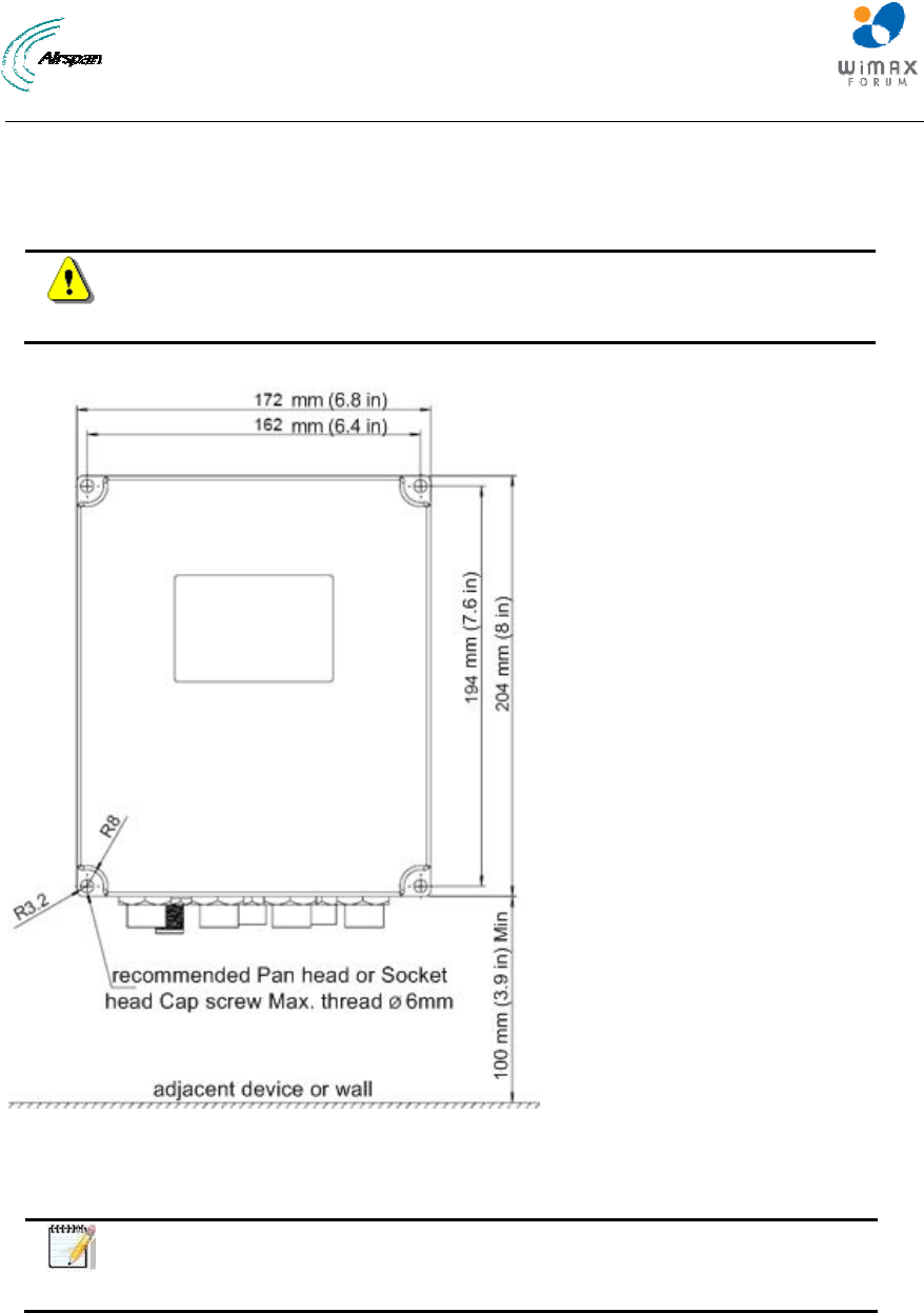
7.1 Mounting the MRTe
Caution: Mount the MRTe in an orientation such that its port panel is
accessible after mounting. This facilitates easy cable connection and
disconnection.
The MRTe provides mounting holes for attachment, as displayed in the figure below.
Figure4‐Mountingtemplate
Align the MRTe's four holes with the cabinet bracket holes, and then insert a screw (not supplied)
through the holes, slide on a washer spring washer and nut and then tighten.
Note: Airspan does not provide screws for attaching the MRTe. The screw
size depends on the cabinet structure or surface to which the MRTe is to be
attached.
Recommend screw type required:
• Size: M6
• Length: 65mm minimum, (Depending on assembly conditions)
• Head: Pan Phillips head.
• Recommended material: SST

Airstream 4001 F49-MRT User Guide
Page 19 Commercial in Confidence UWB-D00211 Rev B
8 Network Cabling
The MRTe interfaces with the subscriber's network through the RJ-45 cable.
Note: Use CAT-5e shielded cable only.
8.1 Connecting to Network
The MRTe provides two RJ-45 (10/100/1000BaseT) ports for interfacing with the subscriber's
network.
The ports of the MRTe support Auto Negotiation, allowing automatic configuration for the highest
possible speed link, and Full Duplex or Half Duplex mode. Therefore, the speed of the connected
device (e.g. PC) determines the speed at which packets are transmitted through the specific port.
In addition, the MRTe ports support MDI/MDI-X automatic crossover, allowing connection to
straight-through or crossover CAT-5e cables. Therefore, these ports can be connected to either a
hub (i.e. using crossover cables) or a PC (i.e. using straight-through cables).
The cable setup for MRTe connectivity is as follows:
¾ Cable: Straight-through (e.g. when connecting to PC) or crossover (i.e. when connecting
to a hub) CAT 5e Ethernet cable
¾ Connectors: 8-pin RJ-45 at both ends
Airstream 4001 F49-MRT User Guide
Page 20 Commercial in Confidence UWB-D00211 Rev B
9 Connecting to Power
The MRTe is powered from the 12/24 VDC power cable that is connected to the vehicle’s power
source.
The input power for the MRTe is 10-30 VDC.
Caution: Before powering on the MRTe, ensure that some type of equipment
such as anantenna or an RF attenuator is connected to the RF jacks. This
eliminates the risk of irreversibly damaging the MRTe.
Caution: Connect the 12/24VDC power cable to the power source only after
the all connections are fully assembled.

Airstream 4001 F49-MRT User Guide
Page 21 Commercial in Confidence UWB-D00211 Rev B
10 Initial Procedure for Web-Based Management
This chapter contains information on the Web-based Graphical User Interface (GUI). The GUI
enables quick and simple setup, and discusses the following topics:
¾ Browser Requirements
¾ Configure and Connect
¾ Accessing the MRTe via the Web
10.1 Browser Requirements
Ensure that your Web browser with which you want to access the Airstream 4001 F49-MRT is
running Microsoft Internet Explorer 8, Firefox 3.0 and above.
This section describes the initial procedure for Airstream 4001 F49-MRT operation and how to
initially connect the MRTe to the base station.
10.2 System Configuration and Login
This chapter describes how to configure the CPE and to connect it to the base station.
User computer can get IP address automatically from CPE. The CPE’s default login values are
listed below:
¾ HTTP CPE address:
• 10.1.1.1 (subnet 255.255.255.0)
¾ User name: "root"
¾ Password: "admin"
Note: The following screens shots are for illustration purposes only.
10.2.1 Accessing the Airstream 4001 F49-MRT
Proceed with login and connect to the Airstream 4001 F49-MRT.
To access the Airstream 4001 F49-MRT Web server:
1. Start your web browser (e.g. Microsoft Internet Explorer).
2. In the Address Bar field, enter the IP address of the Airstream 4001 F49-MRT (i.e. 10.1.1.1)
subnet (255.255.255.0).
Note: To quickly enter the Airstream 4001 F49-MRT server address, you can
simply type the IP address without typing "http://". When you press <Enter>
(see Step 3), the full address (i.e. "http://...") is automatically entered.
3. Press <Enter> on your keyboard.
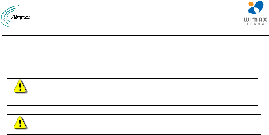
The Login page of the Airstream 4001 F49-MRT web-based management opens, as displayed
below:
Airstream 4001 F49-MRT User Guide
Page 22 Commercial in Confidence UWB-D00211 Rev B
Figure5‐Login
4. In the User Name field, enter your user name, default = root.
5. In the Password field, enter your password, default = admin.
6. Click Login to enter
Note: It is highly recommended to change your Password after initial login.
The Airstream 4001 F49-MRT server home page opens, Status, displaying current information of
the Airstream 4001 F49-MRT System version and Network information, as displayed below.
Figure6‐MRTe‐Status
10.3 Navigating Your Airstream 4001 F49-MRT Management
The Airstream 4001 F49-MRT provides a user-friendly graphical user interface (GUI) that allows
you to easily access commands for configuring Airstream 4001 F49-MRT. The table below
describes basic Airstream 4001 F49-MRT navigation procedures.
10.3.1 Menus
The menu buttons at the top of the page provides links to various configuration categories. These
menu buttons are displayed throughout the Airstream 4001 F49-MRT management pages to
allow easy navigation between categories.

Airstream 4001 F49-MRT User Guide
Page 23 Commercial in Confidence UWB-D00211 Rev B
The Airstream 4001 F49-MRT menus are described in the table below:
Table6‐Airstream4001F49‐MRTMenus
Menu Description
Status Opens the Status page where the following system status information
(read-only) is displayed:
WiMAX Status:
¾ System Status
¾ Physical Status
¾ Uplink
¾ Downlink
¾ Service Flow
Network Status:
¾ LAN
¾ WAN
¾ WiFi
Device Info:
¾ Device Information
System Opens the System page where:
¾ SW Download
¾ Set Default
¾ Reboot
WiMAX Opens the WiMAX page where the following information is displayed and
defined:
¾ Scanner
¾ Authentication Selection
Networking Opens the Networking page where mode configurations are performed:
¾ Mode
¾ DMZ
¾ Extended DMZ
Logout Logs out of the system
10.3.2 Navigating
The table below describes basic Airstream 4001 F49-MRT management navigation procedures:
Table7‐Navigation
To ... Do this ...
Navigate to a specific category Click the relevant menu.
Quit the web-based tool Close the web tool window.
Note: The following displayed screens are for illustration purposes only.
Airstream 4001 F49-MRT User Guide
Page 24 Commercial in Confidence UWB-D00211 Rev B
11 Status
The Status page is used for viewing system status information (read-only) related to the CPE and
its related parameters and connections.
To return to the Status page at any time click the Status button.
To access the Status page:
1. Click Status to navigate to the Status page.
2. Click the desired sub-option on the drop down list.
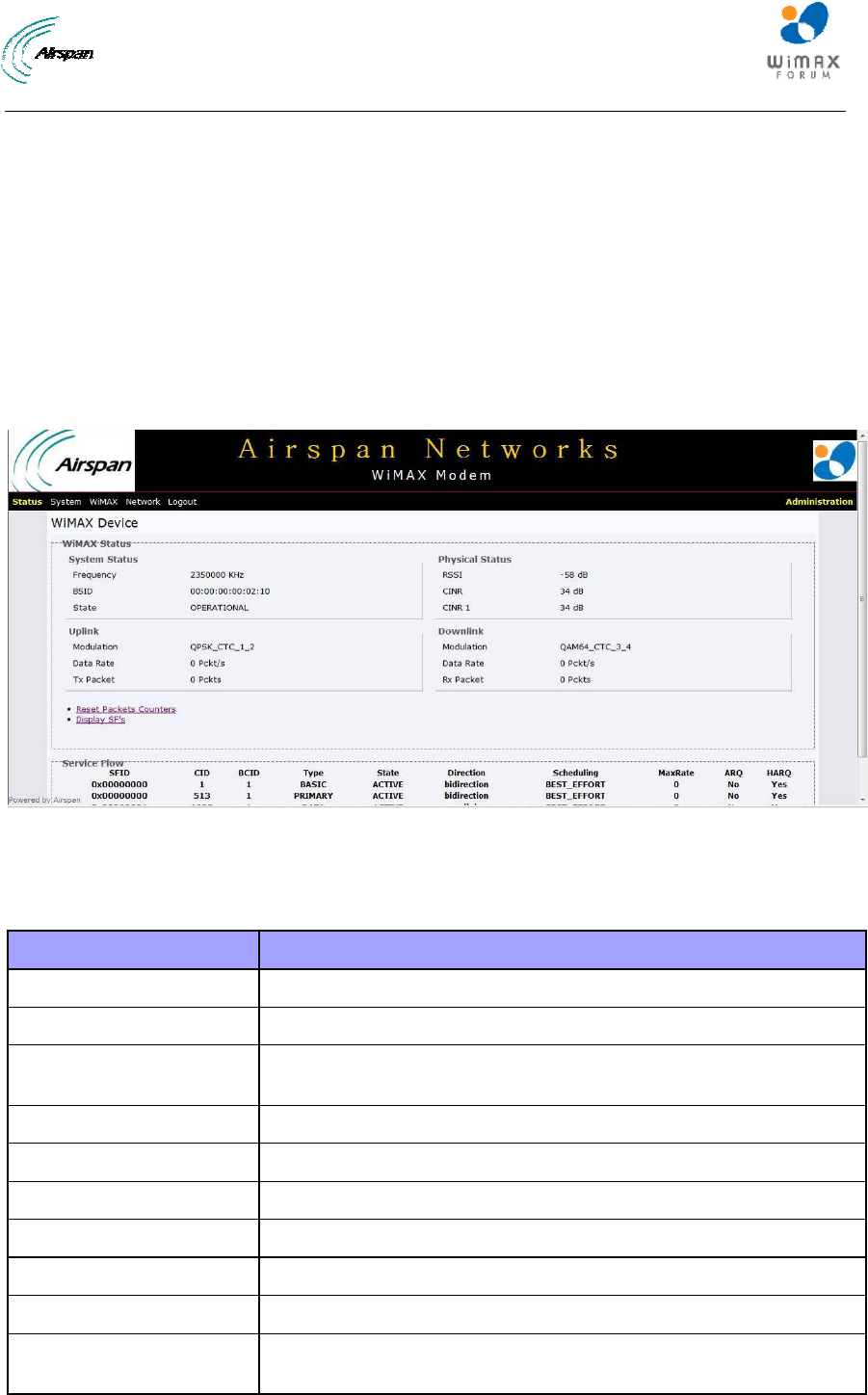
11.1 WiMAX Status
To view WiMAX status related parameters on the Status page:
1. Click on Status to open the drop down list and choose the WiMAX Status sub-option.
Figure7‐WiMAXStatus
The parameters displayed (read-only) on the WiMAX Status page are described in the table
below:
Table8‐WiMAXStatuswithSFdisplayed
Parameter Description
WiMAX Status
System Status Displays System status information
Frequency Displays the current frequency being used. While scanning the
frequency display will fluctuate until frequency is located
Bandwidth Displays the bandwidth used
BSID Displays the Base Station ID
State Displays the current state of the CPE
Physical Status Displays Physical status information
RSSI Displays the RSSI (Received Signal Strength Indicator) value
CINR Displays the CINR (Carrier to Interference Noise Ratio) value
CINR 1 Displays the CINR (Carrier to Interference Noise Ratio) value
for reuse1 zone
Airstream 4001 F49-MRT User Guide
Page 25 Commercial in Confidence UWB-D00211 Rev B
Parameter Description
CINR3 Displays the CINR (Carrier to Interference Noise Ratio) value
for reuse3 zone
Uplink Displays Uplink information
Modulation Displays the current uplink modulation
Data rate Displays the current uplink data rate
TX Packet Displays number of transmitted packets
Downlink Displays Downlink information
Modulation Displays the current downlink modulation
Data Rate Displays the current downlink data rate
RX Packet Displays number of received packets
Refresh Packets
Counters Click to manually refresh the packet counters
Display SFs Click to display service flows
Service Flow Displays the service flow information
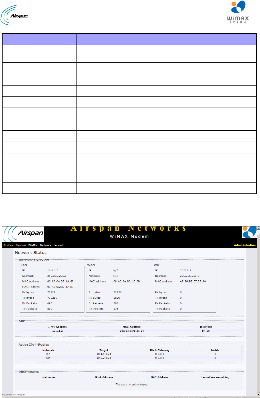
11.2 Network Status
To view Network Status related parameters on the Status page:
1. Click on Status to open the drop down list and choose the Network Status sub-option.
Figure8‐NetworkStatus
Airstream 4001 F49-MRT User Guide
Page 26 Commercial in Confidence UWB-D00211 Rev B
The parameters displayed (read-only) on the Network Status page are described in the table
below:
Table9‐Networkstatus
Parameter Description
Interface Overview Displays current data for LAN, WAN and WiFi interfaces.
ARP Displays the current status of the ARP table.
• Ipv4-Address - displays address
• MAC-Address - displays address
• Interface - displays
Active IPv4 Routes Displays the current status of the Routing table.
• Network - displays type (WAN, LAN)
• Target - displays target IP
• Ipv4-Gateway - displays GW
• Metric -
Interface Overview Displays an overview of the Interface
• Interface - displays type - WAN, LAN, WiFi
• IP address and Netmask of the interface.
• MAC - displays the MAC address of the port’s physical
interface.
• Transfer - displays the RX (received) & TX (transmission)
bytes, including number of packets.
DHCP leases • DHCP leases - for Router Mode only
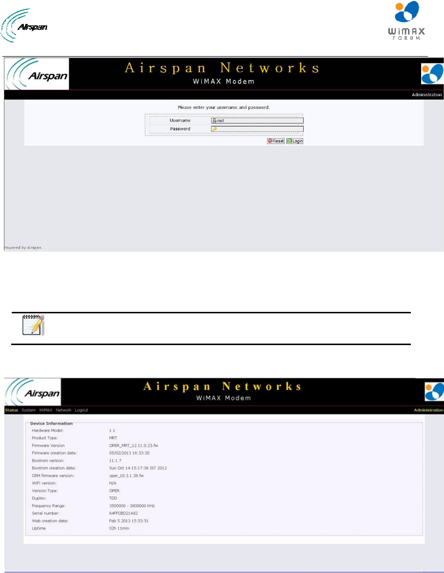
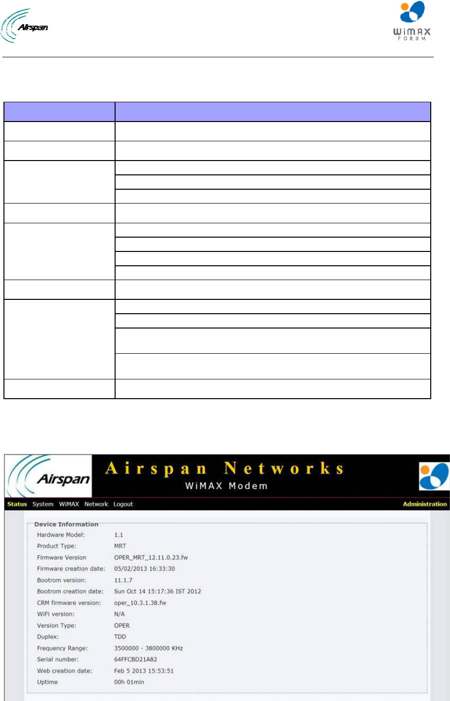
11.3 Device Information
To view Device Information related parameters on the Status page:
1. Click on Status to open the drop down list and choose the Device Information sub-option.
Figure9‐DeviceInformation

Airstream 4001 F49-MRT User Guide
Page 27 Commercial in Confidence UWB-D00211 Rev B
The parameters displayed (read-only) on the Device Information page are described in the table
below:
Table10‐DeviceInformation
Parameter Description
Device Information Displays information on the device being used.
Hardware Model Displays the hardware model.
Product Type MRT
Firmware Version Displays the firmware version in use.
Firmware creation date Displays the date the firmware was created.
Bootrom version Displays the bootrom version number.
Bootrom creation date Displays the bootrom creation date.
CRM firmware version Displays the firmware version of the radio module
WiFi version Displays the SW version of WiFi mode.
Version Type Displays always operational.
Duplex Displays the radio duplex mode.
Frequency range Displays the frequency range for the device.
Serial number Displays serial number of the device.
Uptime Displays the amount of time the system has been up and running.
Airstream 4001 F49-MRT User Guide
Page 28 Commercial in Confidence UWB-D00211 Rev B
12 System
To access the System page:
1. Click System to navigate to the System page.
2. Click the desired sub-option on the drop down list.
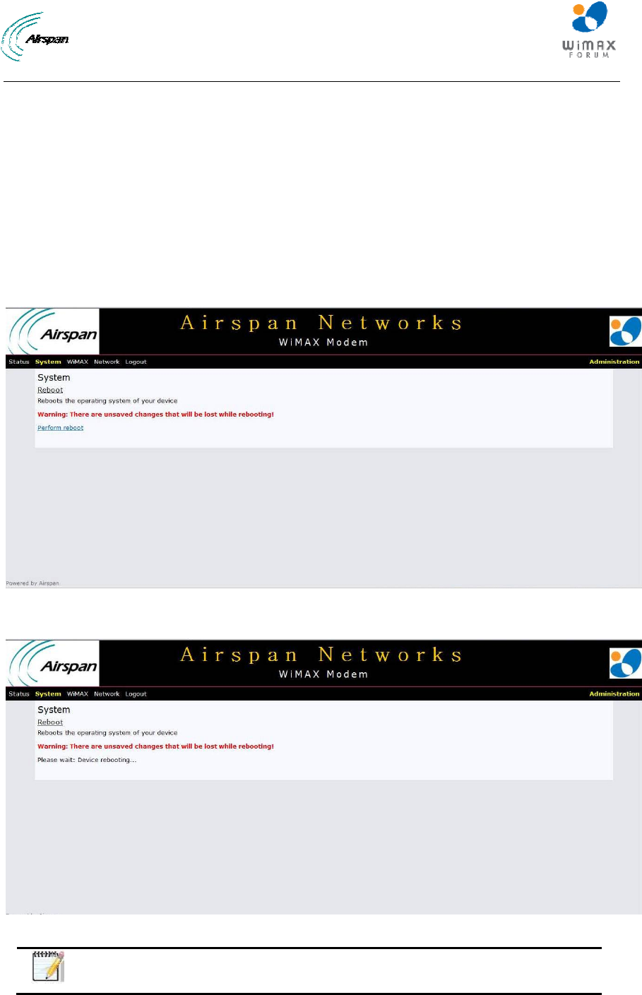
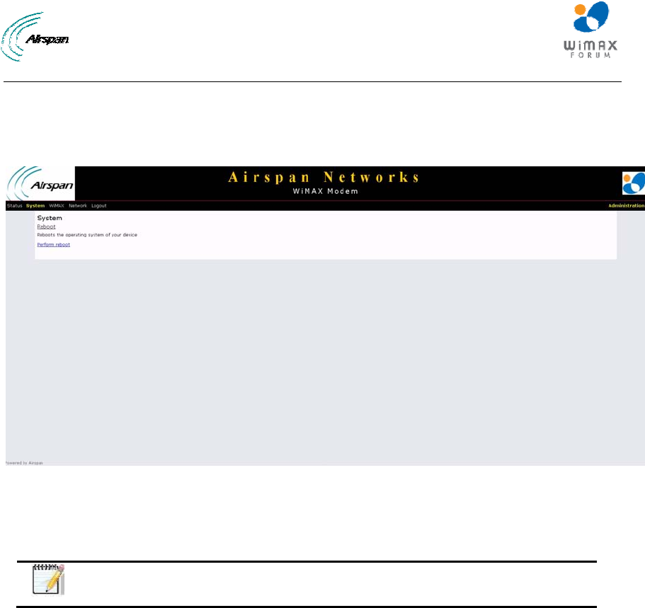
12.1 Reboot
Some configuration settings require a restart of the unit to apply new parameter settings to the
device, such as upgrading the software version. In order for upgrades and/or other changes to
take effect the CPE must be rebooted, as shown below:
To perform a Reboot
1. Click on System to open the drop down list and choose the Reboot sub-option.
Figure10‐SystemReboot
2. Click Perform reboot. Progress is displayed (shown below).
Figure11‐SystemRebootprogress
Note: After system reboots, logging-in is required.
Airstream 4001 F49-MRT User Guide
Page 29 Commercial in Confidence UWB-D00211 Rev B
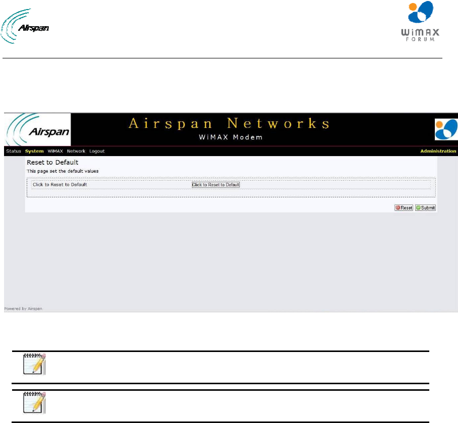
12.2 Reset to Default
To set the product parameters to factory default settings:
1. Click on System to open the drop down list and choose the Reset to Default sub-option.
Figure12‐System‐ResettoDefault
2. Click on Click to Reset to Default to reset to factory defaults. Reset to cancel.
Note: The Reset and Submit buttons are unavailable on this page.
Note: After system reboots, logging-in is required.
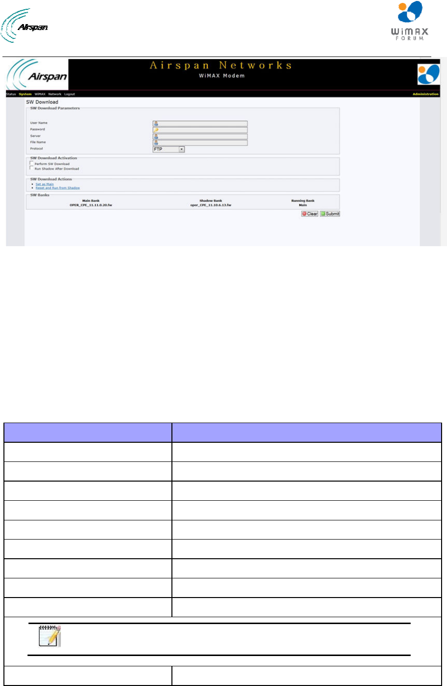
12.3 Software Download
The Software page allows you to upgrade the software by downloading a new version. New
software releases can be downloaded periodically when available. Software upgrade is performed
by downloading a software version file to the device using File Transfer Protocol (FTP) or Trivial
File Transfer Protocol (TFTP). To upgrade the device, it is necessary to define the FTP
parameters and the name of the software version file to be downloaded. The downloaded file is
initially downloaded to the device's Shadow SW bank.
To Download Software:
1. Click on System to open the drop down list and choose the Software Download sub-option.
Airstream 4001 F49-MRT User Guide
Page 30 Commercial in Confidence UWB-D00211 Rev B
Figure13‐SystemSoftwareDownload
2. Configure the software upgrade parameters.
3. Check Perform SW Download and Run Shadow after Download.
4. Click Submit.
After the download is completed the downloaded SW file will replace the existing file in the
Shadow bank and the unit will reboot from the Shadow version.
5. Click on Click to Set as Main - to set the file as the main active SW version immediately.
When the unit runs for 5 minutes and the WiMAX link remains stable for the past 1 minute running
the new SW version it will be set as the Main version automatically. If not, the unit will reboot from
the Main version (previously used).
The parameters displayed on the Software Download page are described in the table below:
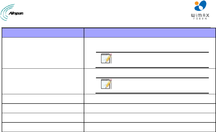
Table11‐SoftwareDownload&SoftwareBanks
Parameter Description
SW Download
Username Enter - Username for access to the FTP server
Password Enter - Password for access to the FTP server
Protocol FTP/TFTP - protocol for file transfer
Server Enter - IP address of the FTP server
File name Enter - Name of the file to be loaded
SW Download Activation
Perform SW Download Check to perform software download
Run Shadow after Download Check to cause CPE to reboot shadow file
Note: Changes will only take affect after clicking on Submit.
SW Bank Selection
Airstream 4001 F49-MRT User Guide
Page 31 Commercial in Confidence UWB-D00211 Rev B
Parameter Description
Click to Set as Main The downloaded SW file is immediately set as the Main
bank
Note: this operation is allowed only if
running from Shadow version.
Click to Reset and Run from
Shadow
To reset and run the SW from the Shadow bank
Note: this operation is allowed only
when running from main version.
SW Banks Info
Main Bank Displays the software stored in the Main bank
Shadow Bank Displays the software stored in the Shadow bank
Running Bank Displays the location of the currently running SW file
Airstream 4001 F49-MRT User Guide
Page 32 Commercial in Confidence UWB-D00211 Rev B
13 WiMAX
The WiMAX page is used to configure WiMAX scanning for a connection with a base station and
enables you to add, delete and edit channels that the device will use during initial scanning.
To access the WiMAX page:
1. Click WiMAX to navigate to the WiMAX page.
2. Click the desired sub-option on the drop down list.
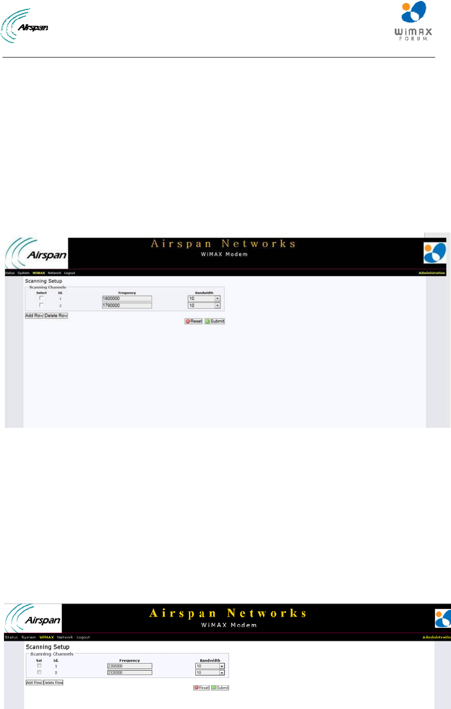
13.1 Scanning Setup
The Scanning Setup page allows users to stop or start WiMAX connection with a BS, as
displayed below:
To access the Scanning Setup page:
1. Click on WiMAX to open the drop down list and choose the Scanner sub-option.
Figure14‐WiMAX‐Scanner‐Channels
13.1.1 Channels
The Channels page lists all the scanning channels that are stored in the channel table along with
channel status associated to the channel currently used to connect the CPE to a BS. Here one
can add, remove, and edit channels in the channel table.
¾ ID - will display the active channel. This channel is used for the current wireless connection.
¾ Frequency - the channel frequency in KHz.
¾ Bandwidth - the channel bandwidth from the available list. Channel bandwidth - values are:
3.5MHz, 5MHz, 7MHz and 10MHz.
13.1.2 Scanning Setup
The Scanning Setup page enables you to add, delete and edit channels, as shown below:
Figure15‐ScanningSetup
Airstream 4001 F49-MRT User Guide
Page 33 Commercial in Confidence UWB-D00211 Rev B
To add a new channel:
1. Click Add Row - to add new Channel row. Id. Number will be added automatically in
ascending order.
2. Enter Frequency
3. Enter Bandwidth
4. Click Reset to discard any changes
Or
Click Submit to save the changes.
5. Click Save and Apply to apply changes immediately
To delete a channel:
1. Check Sel - to select the Channel row to delete
2. Click Delete Row to remove a channel from the list
After Bandwidth range changes, reboot the system in order for the new configurations to take
effect.
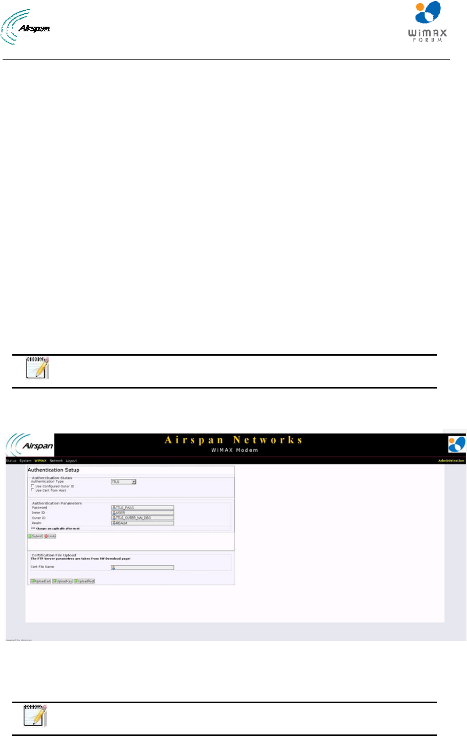
13.2 Authentication
The Authentication settings page of the Airstream 4001 F49-MRT management allows you to
enable and define a method of authentication, mechanism and manage the certificates of the unit.
Additionally you can select one of five key encoding methods listed in “Phase 2”. Identity,
username, and password should be entered with respect to the BS, if authentication is required.
Note: PEM (Privacy Enhanced Mail, Base64 encoded DER certificate) is the
only certificate format supported.
To set Authentication:
1. Click on WiMAX to open the drop down list and choose the Authentication sub-option.
Figure16‐WiMAX‐Authentication
13.2.1 Authentication Status
Enable and define Authentication type.
Note: TTLS = EAP-TTLS and TLS = EAP-TLS

Airstream 4001 F49-MRT User Guide
Page 34 Commercial in Confidence UWB-D00211 Rev B
To select type of Authentication:
2. Click on the Authentication Type drop down list and choose either:
• TTLS - to enable EAP-TTLS Authentication
• TLS- - to enable EAP-TLS Authentication
• None - to disable Authentication
For EAP-TTLS Authenication:
a. Check Use Configured Outer ID - Identity can be either:
o Generated randomly (unchecked)
or
o Manually defined, check Use Configured Outer ID
b. Define the Password
c. Define the Username
d. Outer ID - displayed automatically when Use Configured Outer ID is checked
e. Define the Realm
f. After changes, reboot the system in order for the new configurations to take effect
For EAP-TLS upload the certificate to the device:
a. Configure the FTP server information in the Software download screen, including:
Username, Password and Server.
b. Return to the Authentication screen, fill in the certificate file name in the “Cert File
name” field, and click Upload Cert.
c. Next fill in the private key file name in “Cert File name” field, and click UploadKey
d. Finally fill in the root certificate file name in “Cert File name” field and click
UploadRoot
Airstream 4001 F49-MRT User Guide
Page 35 Commercial in Confidence UWB-D00211 Rev B
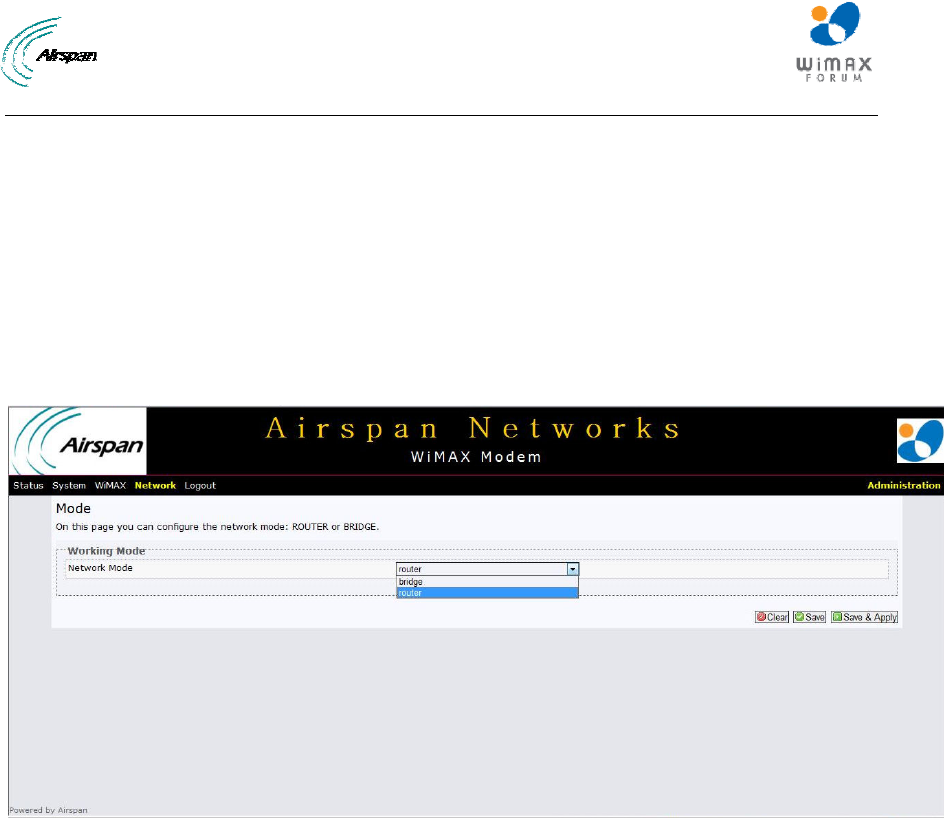
14 Network
The Network page of the Airstream 4001 F49-MRT management enables you to configure Bridge
mode or Router mode.
To access the Network page:
1. Click Network to navigate to the Networking page.
2. Choose the desired sub-option from the drop-down list.
14.1 Mode (Router/Bridge) Configuration
To access the Mode (Router/Bridge) page:
1. Click on Network to open the drop down list and choose the Mode sub-option.
Figure17‐Networking‐Bridgemode
14.1.1 Router Mode - WAN IP Address
To configure the Router Mode page:
2. Select Router Mode - to enable Router Mode.
If the network requires CPE WAN address to be allocated dynamically (by the network), then
choose DHCP option. Else - choose static IP configuration. The “Protocol” parameter controls the
mode:
3. Select Protocol.
If Static IP is chosen, then configure the following parameters:
4. Enter IPv4 address.
5. Select IPv4 Netmask.
6. Enter IPv4 Gateway.
Once finished:
7. Click Clear to discard any changes.
Or
Click Save to save the changes.
8. Click Save & Apply to save changes. To apply immediately a Reset is required.
14.1.2 Bridge Mode - WAN IP Address
To configure the Bridge Mode page:
1. Select Bridge Mode - to enable Bridge mode.
Airstream 4001 F49-MRT User Guide
Page 36 Commercial in Confidence UWB-D00211 Rev B
If the network requires CPE WAN address to be allocated dynamically (by the network), then
choose DHCP option. Else - choose static IP configuration. The “Protocol” parameter controls the
mode:
2. Select Protocol.
If Static IP is chosen, then configure the following parameters:
3. Enter IPv4 address.
4. Select IPv4 Netmask.
5. Enter IPv4 Gateway.
Once finished:
6. Click Clear to discard any changes.
Or
Click Save to save the changes.
7. Click Save & Apply to save changes. To apply immediately a Reset is required.
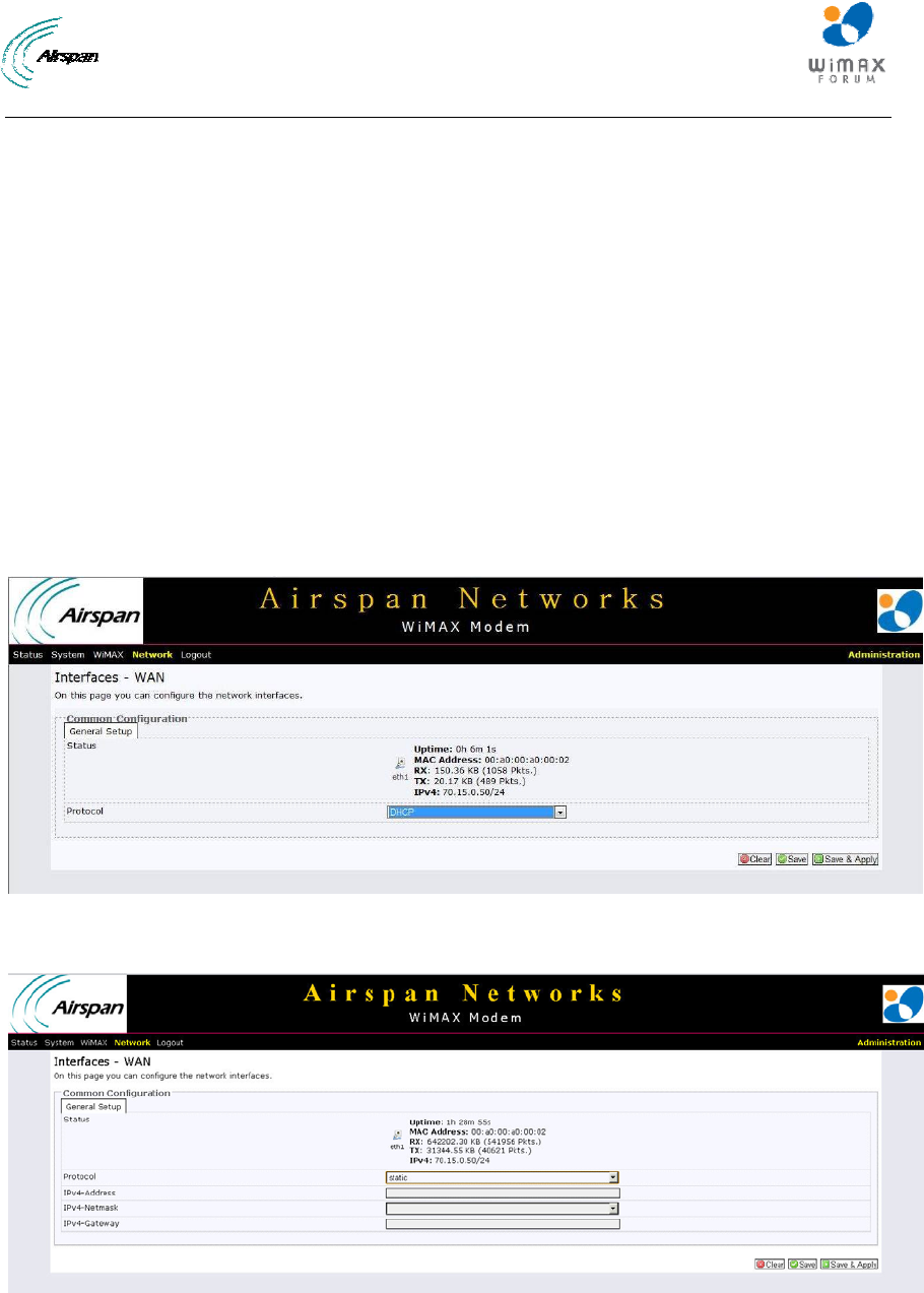
Examples:
WAN IP addressing using DHCP:
Figure18‐WANDHCP
WAN IP addressing using Static IP:
Figure19‐WANStaticIPConfigurations
Airstream 4001 F49-MRT User Guide
Page 37 Commercial in Confidence UWB-D00211 Rev B
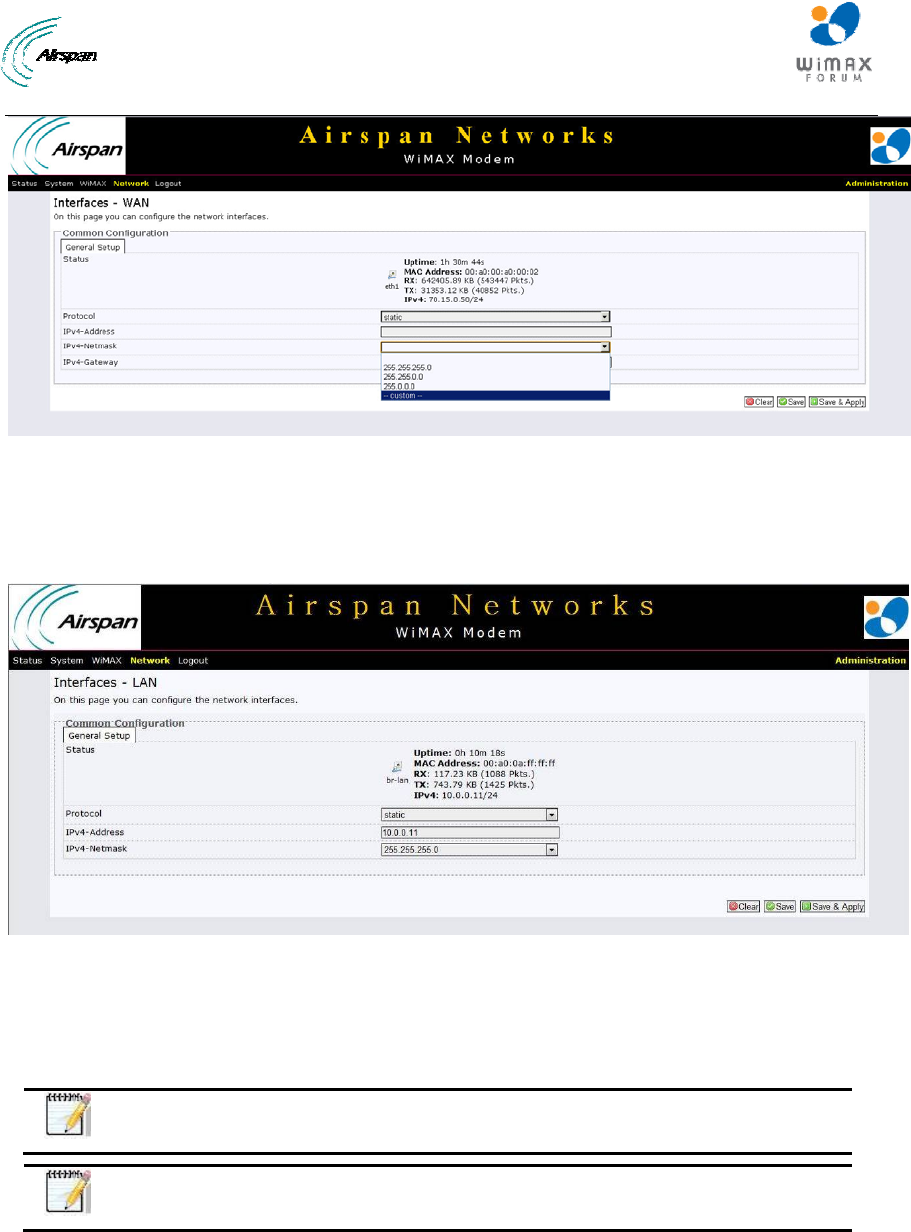
Figure20‐WANStaticIPMaskOptions
14.1.3 LAN IP Configuration
Only Static IP configuration should be used for LAN connection.
LAN Static IP addressing
Figure21‐LANStatic
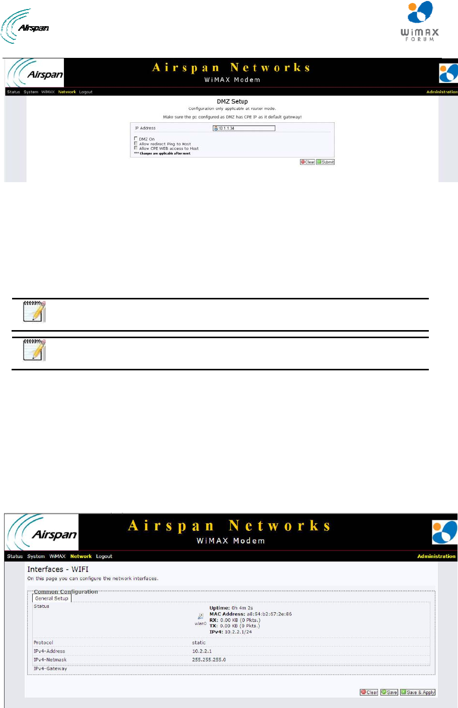
14.2 DMZ
The DMZ (Demilitarized Zone) page is used to allow a single computer on the LAN to be
accessed from the Internet
Note: Configuration of DMZ is only applicable in Router Mode.
Note: Confirm the PC that is configured as the DMZ has CPE IP as its default
gateway.
To access the DMZ page:
1. Click on Network to open the drop down list and choose the DMZ sub-option.
Airstream 4001 F49-MRT User Guide
Page 38 Commercial in Confidence UWB-D00211 Rev B
Figure22‐DMZ
2. Enter the IP address of the computer connected to the CPE’s LAN. The IP address should
be on the same subnet as CPE’s LAN subnet
3. Check DMZ on - to enable DMZ
4. Check Allow redirect Ping to Host - to enable pinging to the PC behind the CPE
5. Check Allow CPE WEB access to Host - to enable web access to the PC behind the CPE
14.3 WiFi
Note: Full WiFi support is currently under development and is planned for the
near future.
Note: In the current version, the default WiFi parameters are not configurable
and are displayed on the Network Status page as read-only
The default WiFi parameters displayed on the Network Status page (read-only) are:
¾ WiFi enabled
¾ SSID: AS_MRT
¾ Security disabled
¾ Interface IP:10.2.2.1, subnet mask 255.255.255.0
¾ DHCP server
To access the WiFi page:
1. Click on Network to open the drop down list and choose the Interfaces - WiFi sub-option.
Figure23‐WiFi

Airstream 4001 F49-MRT User Guide
Page 39 Commercial in Confidence UWB-D00211 Rev B
15 Logout
To quit the Airstream 4001 F49-MRT at the end of a session or for maintenance.
• Click Logout. You will be re-directed to the Login page.
Airstream 4001 F49-MRT User Guide
Page 40 Commercial in Confidence UWB-D00211 Rev B
16 Reboot
Some configuration settings require that you restart the unit to apply new parameter settings to
the device, such as upgrading the software version. In order for upgrades and/or other changes to
take effect the CPE must be rebooted, as shown below:
Figure24‐Airstream4001F49‐MRT‐Reboot
To perform a Reboot
1. Click Reboot. A confirmation warning is displayed.
2. Click Perform reboot. A warning is displayed, “Please wait: Device rebooting…”.
Note: After system reboots, logging-in is required.

Airstream 4001 F49-MRT User Guide
Page 41 Commercial in Confidence UWB-D00211 Rev B
17 Appendix
17.1 Glossary of Terms
BPSK Binary Phase Shift Keying
BS Base Station
BWA Broadband Wireless Access
CID Connection Identifier Number
CPE Customer Premises Equipment (interchangeable with ST)
dB Decibel
dBm Power ratio in dB (decibel) of the measured power referenced to one
milliwatt
DC Direct Current
DL Downlink
DVR Digital Voice Recorder
FDD Frequency Division Duplex
FEC Forward Error Correction
FTP File Transfer Protocol
GHz Gigahertz. One GHz represents 1 billion cycles per second
HFDD Half-Duplex FDD
Hz Hertz
IAD Integrated Access Device
IDU Indoor Unit (i.e. SDA-1 Type II, SDA-4S Type II, or SDA-4S/VL Type II)
IP Internet Protocol
ISP Internet Service Provider
LAN Local-Area Network
MAC Media Access Controller. The next layer up from the PHY.
Mbit/s Megabits per second
MHz Megahertz (one million cycles per second)
MIB Management Information Base
MRT Mobile Radio Terminal
NLOS Non Line-of-Sight radio propagation path
ODU Outdoor Unit (i.e. ProST)
OFDM Orthogonal Frequency Division Multiplexing
QAM Quadrature Amplitude Modulation
QoS Quality of Service, which is used to specify level of data throughput
QPSK Quadrature Phase Shift Keying

Airstream 4001 F49-MRT User Guide
Page 42 Commercial in Confidence UWB-D00211 Rev B
RF Radio Frequency
Rx Receive
SDA-4S Convenient term for either the SDA-4S Type II or SDA-4S/VL adapters
SF Service Flow
SME Small and Medium-sized Enterprise
SNMP Simple Network Management Protocol
SNR Signal-to-Noise Ratio
ST Subscriber Terminal (interchangeable with CPE or SS)
TDMA: Time Division Multiple Access. Technology for delivering digital wireless
service using time-division multiplexing (TDM)
Tx: Transmit
UGS Unsolicited Grant Service. Used to provide fixed bandwidth slots on the
uplink for an ST to transmit data at regular intervals. The bandwidth should
be used by the UGS SF, however the final decision of which SF (if any)
uses the bandwidth slot is made by the ST.
WiMAX WiMAX is a wireless industry coalition whose members are organized to
advance IEEE 802.16 standards for broadband wireless access (BWA)
networks.

Airstream 4001 F49-MRT User Guide
Page 43 Commercial in Confidence UWB-D00211 Rev B
17.2 Revision History
Revision Originator Date Description
Rev A M. Falik 07-2012 Initial document
Rev B M. Falik 04-2013 Additions and
updates
17.3 Contact Information
Customer Service Help-Desk for customer service emergency
Airspan Networks have introduced the Airspan Tracker application to enable prompt and efficient
Customer Support services.
If you do not have an Airspan Tracker account, please obtain login credentials by filling-in the form in
the main page "Register New Account".
Worldwide Headquarters:
Airspan Networks Inc.
777, Yamato Road, Suite 310,
Boca Raton, FL 33431, USA
Tel: +1 561 893 8670
www.airspan.com
Feedback:
To provide feedback on this document, please send comments to the following email address:
documentfeedback@airspan.com