Airspan Networks SYN2500 Base station of LTE fixed cellular system User Manual AirSynergy Installation Guide
Airspan Networks Inc Base station of LTE fixed cellular system AirSynergy Installation Guide
User_manual

UGD-D01001 Rev A
AirSynergy 2000
Installation Guide

AirSynergy 2000 Installation Guide
Page 2 Commercial in Confidence UGD-D01001 Rev A1
Copyright
© Copyright by Airspan Networks Inc., 2013. All rights reserved worldwide.
The information contained within this document is proprietary and is subject to all relevant
copyright, patent and other laws protecting intellectual property, as well as any specific
agreements protecting Airspan Networks Inc. rights in the aforesaid information. Neither this
document nor the information contained herein may be published, reproduced or disclosed to
third parties, in whole or in part, without the express, prior, written permission of Airspan Networks
Inc. In addition, any use of this document or the information contained herein for the purposes
other than those for which it is disclosed is strictly forbidden.
Airspan Networks Inc. reserves the right, without prior notice or liability, to make changes in
equipment design or specifications.
Information supplied by Airspan Networks Inc. is believed to be accurate and reliable. However,
no responsibility is assumed by Airspan Networks Inc. for the use thereof nor for the rights of third
parties which may be effected in any way by the use of thereof.
Any representation(s) in this document concerning performance of Airspan Networks Inc.
product(s) are for informational purposes only and are not warranties of future performance, either
expressed or implied. Airspan Networks Inc. standard limited warranty, stated in its sales contract
or order confirmation form, is the only warranty offered by Airspan Networks Inc. in relation
thereto.
This document may contain flaws, omissions or typesetting errors; no warranty is granted nor
liability assumed in relation thereto unless specifically undertaken in Airspan Networks Inc. sales
contract or order confirmation. Information contained herein is periodically updated and changes
will be incorporated into subsequent editions. If you have encountered an error, please notify
Airspan Networks Inc. All specifications are subject to change without prior notice.
Product performance figures quoted within this document are indicative and for information
purposes only.

AirSynergy 2000 Installation Guide
Page 3 Commercial in Confidence UGD-D01001 Rev A1
Table of Contents
Copyright .......................................................................................................................................... 2
Table of Contents ............................................................................................................................. 3
Summary of Figures ......................................................................................................................... 5
Summary of Tables .......................................................................................................................... 7
Warnings and Cautions .................................................................................................................... 8
Human Exposure to Radio Frequencies ...................................................................................... 8
Radio Interference ........................................................................................................................ 8
Avoiding Radio Interference ......................................................................................................... 8
Modifications ................................................................................................................................. 8
General ......................................................................................................................................... 8
Safety ............................................................................................................................................ 8
Warning of Hazardous Voltages ............................................................................................... 9
Adherence to European Directive 1999/519/EC .......................................................................... 9
Warning Symbols.......................................................................................................................... 9
Service Information ....................................................................................................................... 9
UL Information ............................................................................................................................ 10
Lightning Protection .................................................................................................................... 10
DECLARATION OF CONFORMITY ............................................................................................... 11
FCC Notice ..................................................................................................................................... 12
Federal Communication Commission Notice ............................................................................. 12
GPS Compliance ........................................................................................................................ 12
Maximum Output TX Power ........................................................................................................... 13
Power Consumption ................................................................................................................... 13
Antenna Types............................................................................................................................ 13
Switched Beam Antenna ............................................................................................................ 13
Front Mount Sector Antenna ...................................................................................................... 14
AirSynergy Antenna Usage Options ....................................................................................... 15
1 About this Guide ..................................................................................................................... 17
1.1 Purpose .......................................................................................................................... 17
1.2 Intended Audience .......................................................................................................... 17
1.3 Conventions .................................................................................................................... 17
1.4 Referenced Documentation ............................................................................................ 17
1.5 Organization of this Guide .............................................................................................. 17
2 Introduction ............................................................................................................................. 19
2.1 AirSynergy ...................................................................................................................... 19
2.1.1 Deployment Description.......................................................................................... 19
3 Getting Started ........................................................................................................................ 21
3.1 Workflow of Installation ................................................................................................... 21

AirSynergy 2000 Installation Guide
Page 4 Commercial in Confidence UGD-D01001 Rev A1
3.2 AirSynergy Installation Checklist .................................................................................... 22
4 Verify Prerequisites................................................................................................................. 23
4.1 Verify Site Requirements ................................................................................................ 23
4.2 Verify Installation Requirements ..................................................................................... 23
4.2.1 Verify the Tools ....................................................................................................... 23
4.2.2 Verify the Parts and Kits ......................................................................................... 23
4.2.2.1 Power Supply .......................................................................................................... 25
4.2.3 Verify Components ................................................................................................. 25
4.2.4 Physical Dimensions ............................................................................................... 28
4.2.5 Environmental ......................................................................................................... 29
5 Install AirSynergy .................................................................................................................... 30
5.1 Pole Mount Assembly ..................................................................................................... 30
5.2 Wall Mount Assembly ..................................................................................................... 31
5.3 Front Sector Antenna Assembly ..................................................................................... 32
5.4 Connecting GPS Antenna to AirSynergy ........................................................................ 33
5.5 Securing AirSynergy to the Mounting Plate .................................................................... 35
5.6 LED Display .................................................................................................................... 36
6 Connect and Manage Cables ................................................................................................. 37
6.1 Connecting the Ground Cable ........................................................................................ 37
6.2 Connecting RF Jumper Cables to External Antenna ...................................................... 38
6.3 Connecting the DC Power Cable to AirSynergy ............................................................. 38
7 Power System Connection ..................................................................................................... 40
7.1 Required Tools ............................................................................................................... 40
7.2
Cable Connections
........................................................................................................... 40
7.2.1 DC Power Cable Installation ................................................................................... 40
7.2.2 Network Cable Installation ...................................................................................... 41
7.3 Wiring DC Power Cable to the PSU ............................................................................... 42
7.4 Connecting the AC/DC PSU to Power Supply ............................................................... 44
8 Appendix A ............................................................................................................................. 46
Review Job Sheet ....................................................................................................................... 46
9 Appendix B - Glossary of Terms - Acronym, Abbreviations & Definitions .............................. 47
10 Appendix C - Installation Checklist ..................................................................................... 49
11 Appendix D – PSU for USA ................................................................................................ 50
12 Appendix E ......................................................................................................................... 51
12.1 Revision History .............................................................................................................. 51
12.2 Contact Information ........................................................................................................ 51

AirSynergy 2000 Installation Guide
Page 5 Commercial in Confidence UGD-D01001 Rev A1
Summary of Figures
Figure 1 - AirSynergy with sunshield .............................................................................................. 15
Figure 2 - AirSynergy with front sector antenna ............................................................................. 15
Figure 3 - AirSynergy with switched beam antenna ....................................................................... 16
Figure 4 - AirSynergy 2000 assembled with: Front Mount antenna, sunshield, SBA and sunshield
........................................................................................................................................................ 20
Figure 5 - Workflow of Installation .................................................................................................. 21
Figure 6 - AirSynergy Unit, bottom termination .............................................................................. 27
Figure 7 - AirSynergy Unit, RF ports, Internal Duplexers ............................................................... 27
Figure 8 - AirSynergy Unit, RF ports .............................................................................................. 28
Figure 9 - AirSynergy Unit, RF ports, External Duplexers .............................................................. 28
Figure 10 - AirSynergy mounting plate and hardware .................................................................... 30
Figure 11 - Assemble clamp bands (2 required) ............................................................................ 30
Figure 12 – press down locking mechanism .................................................................................. 31
Figure 13 – tighten clamp bands .................................................................................................... 31
Figure 14 – mounting plate installed on large diameter pole ......................................................... 31
Figure 15 - positioning wall mounting plate .................................................................................... 32
Figure 16 - wall mounting plate fastened on wall ........................................................................... 32
Figure 17 - attaching front mounted antenna to mounting plate .................................................... 33
Figure 18 – Attaching front mount antenna assembly to AirSynergy ............................................. 33
Figure 19 - attaching GPS antenna to mounting bracket ............................................................... 34
Figure 20 - Attaching the GPS antenna assembly to AirSynergy .................................................. 35
Figure 21 - Lift unit to top of mounting plate ................................................................................... 35
Figure 22 - unit engages into slots on the top of mounting plate ................................................... 35
Figure 23 - lift the unit until the bottom studs fit into the bottom slots ............................................ 36
Figure 24 - AirSynergy unit engaged into the bottom slots ............................................................ 36
Figure 25 – attaching ground cable to AirSynergy ......................................................................... 37
Figure 26 - attach ground cable to pole .......................................................................................... 37
Figure 27 - Connecting RF cable .................................................................................................... 38
Figure 28 - weather-proof the connection - external antenna ........................................................ 38
Figure 29 - attaching power cable to AirSynergy ........................................................................... 39
Figure 30 - required tools ............................................................................................................... 40
Figure 31 - DC Power connection .................................................................................................. 41
Figure 32 - Power connection - AirSynergy bottom panel .............................................................. 41
Figure 33 - power and network cable overview .............................................................................. 42
Figure 34 - Waterproof connector exploded view ........................................................................... 42
Figure 35 - power cable preparation............................................................................................... 42
Figure 36 - waterproof connector separated .................................................................................. 42
Figure 37 - gland and connector on cable ...................................................................................... 43

AirSynergy 2000 Installation Guide
Page 6 Commercial in Confidence UGD-D01001 Rev A1
Figure 38 - secure cable to connector ............................................................................................ 43
Figure 39 – power cable wires assembled ..................................................................................... 43
Figure 40 - numbered connector contacts ...................................................................................... 43
Figure 41 - assemble and tighten ................................................................................................... 43
Figure 42 - PSU cable connector assembly ................................................................................... 44
Figure 43 - PSU wires assembled .................................................................................................. 44
Figure 44 - assemble and tighten ................................................................................................... 44
Figure 45 - connector assembled and tightened ............................................................................ 44
Figure 46 - High power (240W) PSU – used for dual AirSynergy installations .............................. 44
Figure 47 - Standard power (150W) PSU – used for standard AirSynergy installation ................. 44
Figure 48 - attaching PSU .............................................................................................................. 45
Figure 49 - PSU for USA deployment ............................................................................................ 45
Figure 50 - PSU for USA ................................................................................................................ 50
Figure 51 - Inside PSU with cable terminations ............................................................................. 50

AirSynergy 2000 Installation Guide
Page 7 Commercial in Confidence UGD-D01001 Rev A1
Summary of Tables
Table 1 - AirSynergy FCC Maximum Output TX Power ................................................................. 13
Table 2 - AirSynergy ETSI Maximum Output TX Power ................................................................ 13
Table 3 - Switched Beam Antenna Parameters - Directional Mode ............................................... 13
Table 4 - Switched Antenna Parameters - Omni Mode .................................................................. 14
Table 5 - Front Mounted Sector Antenna Parameters ................................................................... 14
Table 6 - AirSynergy installation tools ............................................................................................ 23
Table 7 - AirSynergy installation parts and kits .............................................................................. 23
Table 8 - External Antenna and feeder kits (Optional) ................................................................... 25
Table 9 - AirSynergy additional items ............................................................................................. 25
Table 10 - AirSynergy components ................................................................................................ 25
Table 11 - AirSynergy physical dimensions ................................................................................... 28
Table 12 - AirSynergy Environment Compliance ........................................................................... 29
Table 13 - LED Display ................................................................................................................... 36
Table 14 - Glossary of Terms ......................................................................................................... 47
Table 15 - Checklist for Procedure ................................................................................................. 49

AirSynergy 2000 Installation Guide
Page 8 Commercial in Confidence UGD-D01001 Rev A1
Warnings and Cautions
Human Exposure to Radio Frequencies
The AirSynergy antennas should be installed and operated from a minimum safe distance of:
AirSynergy with External Antenna: 1.5m
AirSynergy with Front Mount Antenna: 1.0m
AirSynergy with Smart Beam Antenna (SBA): 0.5m
Radio Interference
This AirSynergy generates, uses, and can radiate radio frequency energy and, if not installed and
used in accordance with the instructions, may cause harmful interference to radio
communications. However, there is no guarantee that interference will not occur in a particular
installation. If this equipment does cause harmful interference to radio or television reception,
which can be determined by turning the equipment on and off, the technician is encouraged to try
to correct the interference by performing one or more of the following measures:
Re-orientate or relocate the antenna
Increase separation between the eNodeBs and/or End Device
Connect the equipment to an outlet on a circuit different from that to which the power
source is connected
Avoiding Radio Interference
Ensure a minimum of 1-meter separation between co-located antennas of AirSynergy units.
Modifications
Any changes and modifications to this device that are not expressly approved by Airspan
Networks may void the user's authority to operate the equipment.
General
Only qualified personnel should be allowed to install, replace, and service the
equipment.
The device cannot be sold retail, to the general public or by mail order. It must be
sold to operators.
Installation must be controlled.
Installation must be performed by licensed professionals.
Installation requires special training. The AirSynergy radio and antenna should be
installed ONLY by experienced installation professionals who are familiar with local
building and safety codes and, wherever applicable, are licensed by the appropriate
government regulatory authorities. Failure to do so may void Airspan's product
warranty and may expose the end user or the service provider to legal and financial
liabilities. Airspan and its resellers or distributors are not liable for injury, damage or
violation of regulations associated with the installation of outdoor units or antennas.
Safety
1. Read this guide and follow all operating and safety instructions.
2. Keep all product information for future reference.
3. This product is supplied with a grounding power plug. Do not defeat this important
safety feature.
4. Warning: High voltages exist inside the product - do not remove the lid or base: No
user serviceable parts inside.
5. Position the power cord to avoid possible damage; do not overload wall outlets.
AirSynergy 2000 Installation Guide
Page 9 Commercial in Confidence UGD-D01001 Rev A1
6. Do not place this product on or near a direct heat source, and avoid placing objects
on the terminal.
7. To avoid electrical shock do not install this device during adverse conditions such as
rain or inclement weather.
8. Use only a damp cloth for cleaning. Do not use liquid or aerosol cleaners. Disconnect
the power before cleaning.
9. The units should not be located near power lines or other electrical power circuits.
10. The radio transceiver must be properly grounded to protect against power surges and
accumulated static electricity. It is the user’s responsibility to install this device in
accordance with the local electrical codes.
11. Installation of the AirSynergy must be contracted to a professional installer.
12. Disconnect Device. The socket outlet should be easily accessible in case you have to
disconnect the device.
13. When installed in the final configuration, the product must comply with the applicable
Safety Standards and regulatory requirements of the country in which it is installed. If
necessary, consult with the appropriate regulatory agencies and inspection
authorities to ensure compliance.
Warning of Hazardous Voltages
On AC installations, hazardous voltages exist. Use caution when verifying or working with AC
power. Remove metal jewelry that could come into contact with AC power.
On DC sections, short circuiting the low voltage, low impedance circuits can cause severe arcing
that may result in burns or eye damage. Remove rings, watches etc. to avoid shorting DC circuits.
Note: Airspan products do not contain hazardous substances (as defined in UK
Control of Substances Hazardous to Health Regulations 1989 and the Dangerous
Substances Regulations 1990). At the end of any Airspan products life cycle, the
customer should consult with Airspan to ensure that the product is disposed of in
conformance with the relevant regulatory requirements.
Adherence to European Directive 1999/519/EC
European Council Recommendation 1999/519/EC details basic restrictions and reference levels
on human exposure to electromagnetic fields as advised by the ICNIRP. Adherence to these
recommended restrictions and reference levels should provide a high level of protection as
regards the established health effects that may result from exposure to electromagnetic fields.
Warning Symbols
The following symbols may be encountered during installation or troubleshooting. These warning
symbols mean danger. Bodily injury may result if you are not aware of the safety hazards involved
in working with electrical equipment and radio transmitters. Familiarize yourself with standard
safety practices before continuing.
Electro-Magnetic Radiation
High Voltage
Service Information
Refer all repairs to qualified service personnel. Do not remove the covers or modify any
part of this device, as this will void the warranty.

AirSynergy 2000 Installation Guide
Page 10 Commercial in Confidence UGD-D01001 Rev A1
Disconnect the power to this product and return it for service if the following conditions
apply:
a. The terminal does not function after following the operating instructions outlined
in this manual.
b. Liquid has been spilled, a foreign object is inside, or the terminal has been
exposed to rain.
c. The product has been dropped or the housing is damaged.
Locate the serial number of the terminal, antenna, and transceiver and record these on your
registration card for future reference. Use the space below to affix serial number stickers.
Also record the MAC address, located on the back of the terminal.
UL Information
- The equipment must be properly grounded according with NEC and other local safety code
requirements.
- Reminder to all the BWA system installers: Attention to Section 820-40 of the NEC which
provides guidelines for proper grounding and, in particular, specifies that the cable ground shall
be connected to the grounding system of the building, as close to the point of cable entry as is
practical.
- AirSynergy is designed to operate in environmental conditions complying with IP66 and relevant
standards.
Lightning Protection
WARNING: The following notes are general recommendations for the system. The wireless
equipment should be installed by a qualified professional installer and must follow local and
national codes for electrical grounding and safety. Failure to meet safety requirements and/or use
of non-standard practices and procedures could result in personal injury and damage to
equipment. A direct lightning strike may cause serious damage even if these guidelines are
followed.
All outdoor wireless equipment is susceptible to lightning damage from a direct hit or induced
current from a near strike. Lightning protection and grounding practices in local and national
electrical codes serve to minimize equipment damage, service outages, and serious injury.
Reasons for lightning damage are summarized as:
- Poorly grounded tower/antenna sites that can conduct high lightning strike energy into
equipment.
- Lack of properly installed lightning protection equipment that can cause equipment failures from
lightning induced currents.
A lighting protection system provides a means by which the energy may enter earth without
passing through and damaging parts of a structure. A lightning protection system does not
prevent lightning from striking; it provides a means for controlling it and preventing damage by
providing a low resistance path for the discharge of energy to travel safely to ground. Improperly
grounded connections are also a source of noise that can cause sensitive equipment to
malfunction.
A good tower grounding system disperses most of the surge energy from a tower strike away
from the building and equipment.
To limit the equipment damage due to a lightning strike, the following practices are recommended
for the wireless system:
- Provide direct grounding from the antenna mounting bracket, the radio and antenna and the
lightning/surge protectors to the same ground point at the base of the tower or a ground bus on
the building. Use the grounding screws on the antenna bracket and the radio and antenna for
terminating the ground wires.
- The AC wall outlet ground must be connected to the same grounding system as the eNodeB.

AirSynergy 2000 Installation Guide
Page 11 Commercial in Confidence UGD-D01001 Rev A1
DECLARATION OF CONFORMITY
European Community, Switzerland, Norway, Iceland, and Liechtenstein
Declaration of Conformity with Regard to the R&TTE Directive 1999/5/EC
English:
This equipment is in compliance with the essential requirements and other relevant provisions of
Directive 1999/5/EC.
Deutsch:
Dieses Gerät entspricht den grundlegenden Anforderungen und den weiteren entsprecheneden
Vorgaben der Richtlinie 1999/5/EU.
Dansk:
Dette udstyr er i overensstemmelse med de væsentlige krav og andre relevante bestemmelser i
Directiv 1999/5/EF.
Español:
Este equipo cumple con los requisitos esenciales asi como con otras disposiciones de la
Directive 1999/5/EC.
Greek:
ΜΕ ΤΗΝ ΠΑΡΟΥΣΑ Airspan ΔΗΛΩΝΕΙ ΟΤΙ Ο ΕΞΟΠΛΙΣΜΟΣ ΣΥΜΜΟΡΦΩΝΕΤΑΙ ΠΡΟΣ ΤΙΣ
ΟΥΣΙΩΔΕΙΣ ΑΠΑΙΤΗΣΕΙΣ ΚΑΙ ΤΙΣ ΛΟΙΠΕΣ ΣΧΕΤΙΚΕΣ ΔΙΑΤΑΞΕΙΣ ΤΗΣ ΟΔΗΓΙΑΣ 1999/5/ΕΚ.
Français:
Cet appareil est conforme aux exigencies essentialles et aux autres dispositions pertinantes de la
Directive 1999/5/EC.
Íslenska:
Þessi búnaður samrýmist lögboðnum kröfum og öðrum ákvæðum tilskipunar 1999/5/ESB.
Italiano:
Questo apparato é conforme ai requisiti essenziali ed agli altri principi sanciti dalla Direttiva
1999/5/EC.
Nederlands:
Deze apparatuur voldoet aan de belangrijkste eisen en andere voorzieningen van richtlijn
1999/5/EC.
Norsk:
Dette utstyret er i samsvar med de grunnleggende krav og andre relevante bestemmelser i EU-
directiv 1999/5/EC.
Português:
Este equipamento satisfaz os requisitos essenciais e outras provisões da Directiva 1999/5/EC.
Suomalainen:
Tämä laite täyttää direktiivin 1999/5/EY oleelliset vaatimukset ja on siinä asetettujen muidenkin
ehtojen mukainen.
Svenska:
Denna utrustning är i överensstämmelse med de väsentliga kraven och andra relevanta
bestämmelser i Direktiv 1999/5/EC.
Român:
Acest echipament este în conformitate cu cerinţele esenţiale şi alte prevederi relevante ale
Directivei 1999/5/CE.
The Declaration of Conformity related to this product can be obtained from PLM@Airspan.com.

AirSynergy 2000 Installation Guide
Page 12 Commercial in Confidence UGD-D01001 Rev A1
FCC Notice
Federal Communication Commission Notice
This equipment has been tested and found to comply with the limits for a Class A digital device,
pursuant to part 15 of the FCC Rules. These limits are designed to provide reasonable protection
against harmful interference when the equipment is operated in a commercial environment. This
equipment generates, uses, and can radiate radio frequency energy and, if not installed and used
in accordance with the instruction manual, may cause harmful interference to radio
communications. Operation of this equipment in a residential area is likely to cause harmful
interference in which case the user will be required to correct the interference at his/her own
expense.
Fixed and base stations transmitting a signal with an emission bandwidth greater than 1 MHz
must not exceed an EIRP of 1000 watts/MHz and an antenna height of 305 m HAAT, except that
antenna heights greater than 305 m HAAT are permitted if power levels are reduced below 1000
watts/MHz EIRP.
GPS Compliance
The GPS is in compliance with the essential requirements and other relevant provisions of
Directive 1999/5/EC."
The GPS complies with the following EMC Common Regulatory Testing standards:
EN55022: Radiated and Conducted Emissions
CISPR 22: Class B
EN 50081-1: Generic Emissions Class B
EN 50082-1: Generic Immunity Class B
EN 61000-4-2: Electrostatic Discharge Immunity
EN 61000-4-3: Radiated RF EM Field Immunity Test
EN 61000-4-4: Electrical Fast Transient/Burst Test
EN 61000-4-6: Conducted Immunity
EN 61000-4-8: Magnetic Field Immunity
Note: A GPS is recommended for synchronizing between LTE sectors.
Note: An optional GPS Lightning/Surge protector is available from Airspan for
lightning prone deployments.
AirSynergy 2000 Installation Guide
Page 13 Commercial in Confidence UGD-D01001 Rev A1
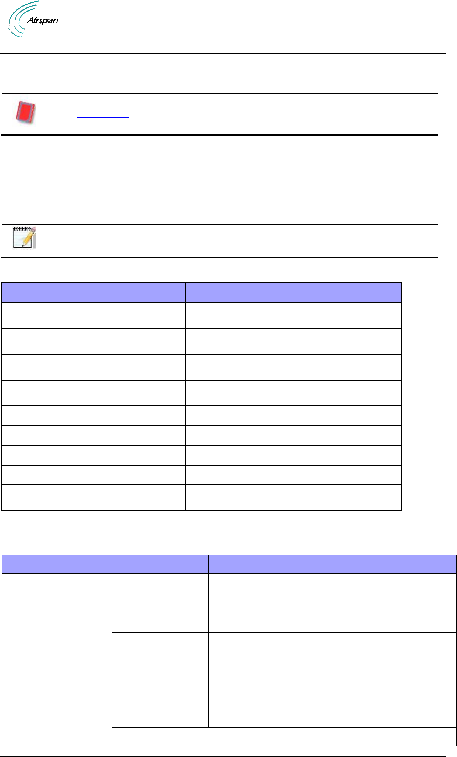
Maximum Output TX Power
Table 1 - AirSynergy FCC Maximum Output TX Power
Frequency Band
FCC
TX EIRP
Antenna Gain
2110-2170 MHz
33.48dBm
50.48dBm
17 dBi
2496-2690MHz
33.65dBm
51.65dBm
18 dBi
2620-2690 MHz
33.36 dBm
51.36 dBm
18 dBi
Table 2 - AirSynergy ETSI Maximum Output TX Power
Frequency Band
ETSI
TX EIRP
Antenna Gain
2110-2170 MHz
33 dBm
50 dBm
17.0 dBi
2496-2690MHz
33dBm
51dBm
18.0 dBi
2560-2630 MHz
33 dBm
51 dBm
18.0 dBi
2620-2690 MHz
33 dBm
51 dBm
18.0 dBi
3400-3500 MHz
33 dBm
51 dBm
18.0 dBi
Caution: Do not set maximum output TX power to higher than local regulations.
Power Consumption
AirSynergy has a Max nominal power consumption of 78W. AirSynergy power consumption is
described in the following table:
Duplex
Tx Power at RF
Port (dBm)
Nominal Power
Consumption (W)
Power Supply
Requirement (W)
FDD
30
80
120
TDD
30
78
120
Antenna Types
The following antennas are designed specifically for AirSynergy deployments. Externally mounted
antennas are available for use as well, but are specified separately.
Note: For a list of compatible external antennas, please contact your nearest
Airspan sales representative.
Switched Beam Antenna
Switched Beam antenna (with built-in GPS antenna) variant include a top mounted steerable
antenna with the following specification. The antenna is a multi-element cross polarized (dual
slant) design which can be used in directional or omni modes of operation.
Table 3 - Switched Beam Antenna Parameters - Directional Mode
Parameter
2.3 GHz
2.6 GHz
3.x GHz
Frequency
2.3 - 2.5 GHz
2.5 - 2.7 GHz
3.4 - 3.7 GHz
AirSynergy 2000 Installation Guide
Page 14 Commercial in Confidence UGD-D01001 Rev A1
Polarization
Dual Slant ±45
Dual Slant ±45
Dual Slant ±45
Polarization
discrimination
14-15 dB
14-15 dB
14-15 dB
Boresight gain
8 dBi
8 dBi
9 dBi
Azimuth HPBW
90±10
90±10
90±10
Elevation HPBW
20
20
20
Co & X-Pol RPE
EN302-326-3 Class
DN1
EN302-326-3 Class
DN1
EN302-326-3 Class
DN1
Grounding
DC Grounded
DC Grounded
DC Grounded
Table 4 - Switched Antenna Parameters - Omni Mode
Parameter
2.3 GHz
2.6 GHz
3.x GHz
Frequency
2.3 - 2.5 GHz
2.5 - 2.7 GHz
3.3 - 3.8 GHz
Polarization
Dual Slant ±45
Dual Slant ±45
Dual Slant ±45
Polarization
discrimination
10-16 dB
10-16 dB
10-16 dB
Average gain
2 dBi
2 dBi
3.5 dBi
Minimum gain ripple
4.5 dBi
4.5 dBi
4.5 dBi
Elevation HPBW
20
20
20
Co & X-Pol RPE
EN 302-326-3
EN 302-326-3
EN 302-326-3
Grounding
DC Grounded
DC Grounded
DC Grounded
Front Mount Sector Antenna
The front mounted sector antenna is a cross polarized fixed antenna which mounts on the front of
the unit in place of the sun-shield.
Note: When using a front mounted antenna, external antennas cannot be
used.
Table 5 - Front Mounted Sector Antenna Parameters
Parameter
2.x GHz
3.x GHz
Frequency
2.3 – 2.7 GHz
3.3 – 3.8 GHz
Polarization
Dual Slant ±45
Dual Slant ±45
Polarization discrimination
>18 dB
>15 dB
Boresight gain
12 dBi
11.5 dBi
Azimuth HPBW
63
65
Elevation HPBW
21
22
Grounding
DC Grounded
DC Grounded
AirSynergy 2000 Installation Guide
Page 15 Commercial in Confidence UGD-D01001 Rev A1
AirSynergy Antenna Usage Options
AirSynergy comes in a range of frequency variants that can be mounted with different
antenna options and formats.
Figure 1 - AirSynergy with sunshield
A typical sector installation will have a cross-polar sector antenna fitted directly to the front of the
AirSynergy main unit. (This is attached instead of the sun-shield).
Figure 2 - AirSynergy with front sector antenna
A switched beam antenna version with built in GPS antenna allows for versatile LTE access,
selecting between omni and n x 90 antenna patterns.
AirSynergy 2000 Installation Guide
Page 16 Commercial in Confidence UGD-D01001 Rev A1
Figure 3 - AirSynergy with switched beam antenna
Note: Appropriate mounting kit (included) for the various external antennas is
required.

AirSynergy 2000 Installation Guide
Page 17 Commercial in Confidence UGD-D01001 Rev A1
1 About this Guide
This section discusses the purpose, intended audience, conventions, referenced documentation
and organization for this guide.
1.1 Purpose
This guide provides the workflow and step-by-step procedures for Installing the AirSynergy.
These procedures include:
Verify prerequisites
Install the AirSynergy radio equipment
Install the PSU equipment (optional)
Connect and manage cables
1.2 Intended Audience
This guide is intended for persons who are responsible for installing the AirSynergy equipment.
These persons should have a working knowledge of the equipment.
1.3 Conventions
This document uses the following informational conventions.
Icon
Description
Checkpoint: Marks a point in the workflow where there may be an exit or branch
to some other procedure. At each Checkpoint the reason for an exit or branch is
given along with specific directions to locate the entry point in the other
procedure.
Reference: Gives a resource in the workflow that may be needed to complete a
procedure along with specific directions to use the resource.
Caution: Describes a possible risk and how to lessen or avoid the risk.
Advice: Provides a recommendation based on best practice.
Note: Provides useful information.
1.4 Referenced Documentation
AirSynergy 2000 Hardware Product Specification
AirSynergy Overview Guide (pending)
AirSynergy LTE Commissioning Manual
1.5 Organization of this Guide
This guide is organized into the following Sections:
About this Guide
Introduction
Getting Started
Verify prerequisites

AirSynergy 2000 Installation Guide
Page 18 Commercial in Confidence UGD-D01001 Rev A1
Install AirSynergy
Install the PSU equipment (Optional)
Connect and manage cables
Power System Connection
Appendixes

AirSynergy 2000 Installation Guide
Page 19 Commercial in Confidence UGD-D01001 Rev A1
2 Introduction
This section provides a descriptive overview of the Airspan’s AirSynergy Pico eNodeB and its
place in the product suite.
2.1 AirSynergy
AirSynergy is part of Airspan’s carrier-class 4G Pico eNodeB family. AirSynergy supports 3GPP’s
Long Term Evolution (LTE) eNodeB, providing high-speed data and mobility, in order to meet the
demands of the Broadband Wireless Access market.
AirSynergy is a compact, easy to install pico-cell, allowing an operator to deploy LTE broadband
services using existing Street Furniture (e.g. street lamps, power poles, etc…)
AirSynergy employs Software Defined Radio (SDR) technology, together with two transmit and
receive paths, antennas and a GPS receiver - all in a highly integrated, physically small and light,
All-Outdoor package, targeted to blend seamlessly into the urban environment. This very compact
outdoor product minimizes physical footprint, power consumption and operator OPEX.
AirSynergy supports a wide array of frequencies and channel sizes, able to operate in both
licensed and unlicensed bands with more frequencies and channel sizes added regularly.
AirSynergy implements dual 30dBm (2 x 1W) transmitters, with several optional integral antennas
and external antennas connectivity.
All Airspan eNodeB products, including AirSynergy, are interoperable with a rich portfolio of 3rd
party end user devices, including many handsets, indoor UEs, outdoor UEs and USB dongles
from several ODMs, using various chipsets. For an updated of interoperability list, please contact
your nearest Airspan Sales Representative.
Note: For management please refer to the AirSynergy LTE Commissioning
Manual as well as the Netspan User Manual.
2.1.1 Deployment Description
A highly flexible and scalable 4G Base Station, the AirSynergy is capable of supporting LTE
profiles across multiple frequency bands.
Note: The following is for illustration only; actual layout may differ as
infrastructure is installation-specific.
Note: AirSynergy must be properly grounded according with NEC and other
local safety code requirements.
Note: Installation of the GPS Lightning/Surge protector (ordered separately)
is necessary to protect the GPS antenna. The Lightning/Surge protector must
be properly grounded with NEC and other local safety code requirements.
Note: An External Duplexer is required for some lower frequency (<1GHz)
FDD variants (supplied with AirSynergy, where required).
AirSynergy 2000 Installation Guide
Page 20 Commercial in Confidence UGD-D01001 Rev A1
Figure 4 - AirSynergy 2000 assembled with: Front Mount antenna, sunshield, SBA and sunshield
Note: Auto-negotiation must always be enabled on the core network side.
Note: Illustration above display the GPS connected directly to the top of the unit,
there is also a remote GPS antenna option.
AirSynergy 2000 Installation Guide
Page 21 Commercial in Confidence UGD-D01001 Rev A1
3 Getting Started
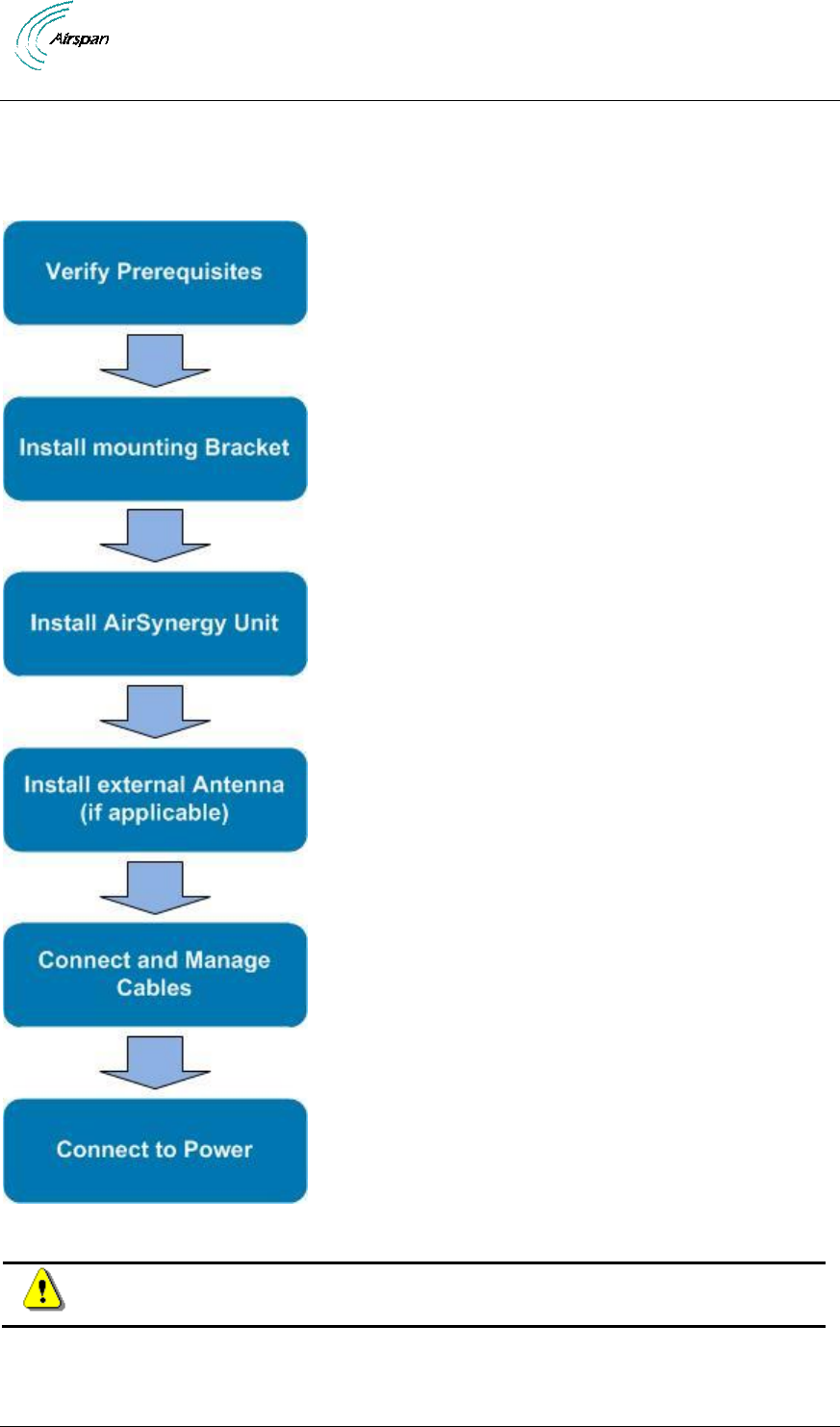
3.1 Workflow of Installation
The Workflow to install the AirSynergy is shown in the following diagram:
Figure 5 - Workflow of Installation
Caution: Antennas must be connected and attached before AirSynergy is
powered on.

AirSynergy 2000 Installation Guide
Page 23 Commercial in Confidence UGD-D01001 Rev A1
4 Verify Prerequisites
Prior to installing the AirSynergy, verify the required safety, power, tools, parts and components.
Reference: Set up requirements for the installation is detailed in the Job Sheet,
see Appendix A for this guide.
4.1 Verify Site Requirements
To set up the AirSynergy, an IP connection to a Netspan server is required.
4.2 Verify Installation Requirements
4.2.1 Verify the Tools
Note: AirSynergy variants with Sunshield, front mounted and Switched Beam
antennas come pre-assembled from the production line.
Table 6 - AirSynergy installation tools
Tool
Use
Large flat bladed screwdriver
securing the pole straps
13mm wrench x 2
heavy-duty pole clamp option only
10mm or 13/32 inch wrench
AirSynergy securing flange nuts
Large pliers
Tightening cable glands - To fit 15mm
Knife
For stripping insulation
Wire cutters
Wire strippers
Cutting of insulation
Ring terminal crimp tool
Tilt-meter
If accurate down-tilt of antenna needs to be set
4.2.2 Verify the Parts and Kits
Table 7 - AirSynergy installation parts and kits
Installation Kit / Part
Part No.
Consisting of
Note:
Main AirSynergy
parts
SYN-U-PMK-2
1 x AirSynergy Universal
Mounting Plate and pole
strap kit
Includes 2 pole straps
for poles up to 200mm
diameter (minimum
pole diameter 50mm)
SYN35-xx-xx-xxx-
xxx
AirSynergy unit(s)
Frequency band and
assembly type-specific
Verify order and
requirements to
ensure the correct
unit type is being
installed.
Optional Accessories

AirSynergy 2000 Installation Guide
Page 24 Commercial in Confidence UGD-D01001 Rev A1
Installation Kit / Part
Part No.
Consisting of
Note:
SYN-SUN-KT-1
1 x Sun Shield (Spare
Unit)
Sun shield with
included hardware
(6 Flathead screws)
SYN-SEC-MKT-1
1 x Sector Antenna
mounting plate with fixing
kit
4 M4 nuts
4 M4 flat washers
4 M4 spring washers
4 Cable ties
4 M5 SEM
SEC60D-x.x-SYN-
RC-x
1 x Sector Antenna (front
mount)
GPS-SYN-KIT
GPS Antenna kit
Bracket
M6 screw
M6 plain washer
M6 spring washer
TNC to TNC cable
(25cm)
Connecting cables
Grounding cable
M6 Lug at each end
Power Supply and
power cable
SYN-PSU-OD-AC-3
Optional AC/DC 150W
PSU module
1 per AirSynergy unit
PWR-xx-INST-2
DC Power cable
1 per AirSynergy unit
with external grade
power cable with
compatible power wea
ther-proof connector
(variable lengths)
SYN-PWR-JOIN-1
Cable Join kit
1 per AirSynergy unit
SYN-PSU-ODUL-
AC-3
Optional AC/DC 150W
PSU in weatherproof
enclosure (NEMA
approved)
Alternative to the
standard 48V PSU
(required for all North
American
installations)
AirSynergy 2000 Installation Guide
Page 25 Commercial in Confidence UGD-D01001 Rev A1
Table 8 - External Antenna and feeder kits (Optional)
Installation Kit / Part
Note
External Antenna
Several variants - Verify the
correct unit type is being
installed.
Typically a 2 port dual-slant cross-polar antenna
Pole mounting kits (supplied with antenna)
Antenna RF Cable
Variable length Heliax RF cables (for mounting antenna
on the same pole immediately behind the AirSynergy unit
or where the Antenna needs to be mounted away from the
AirSynergy unit)
Table 9 - AirSynergy additional items
Additional Common Accessories
(not provided by Airspan)
CAT-5e RJ45 network cable
Cable ties
Self-amalgamating tape
Black PVC tape
Ring terminal for ground cable. M6
Ground cable (4-6 mm) (yellow and green cable)
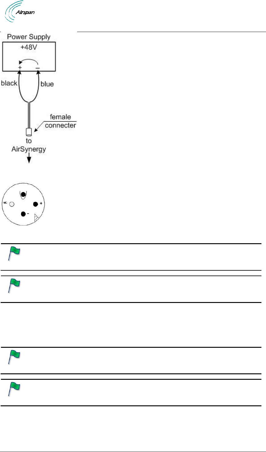
4.2.2.1 Power Supply
AirSynergy supports direct connection to DC power source (-48V DC):
Operational Voltage Range: -40.5 to -57 VDC
Transient Voltage: +150V (ETR283).
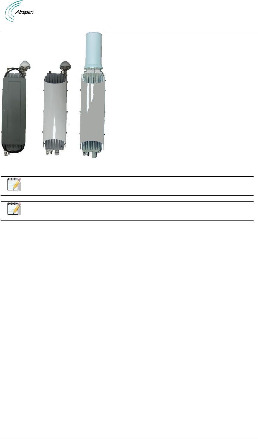
4.2.3 Verify Components
The following figures display various AirSynergy components and accessory kits.
Note: AirSynergy variants with Sunshield, front mounted antenna and Switched
Beam antenna come factory pre-assembled.
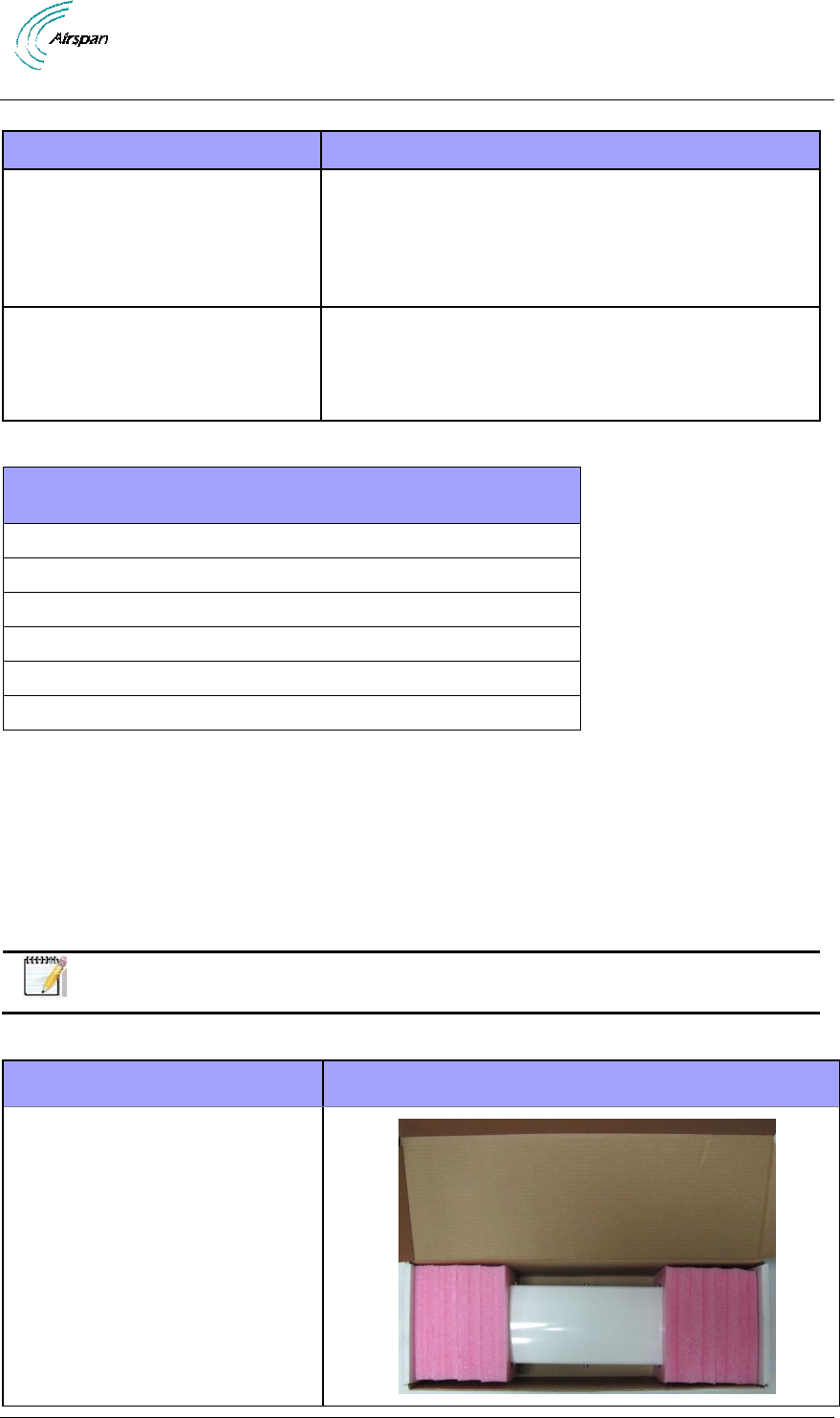
Table 10 - AirSynergy components
Parts
Images
AirSynergy Unit (with Sunshield)
in typical packing box
AirSynergy 2000 Installation Guide
Page 26 Commercial in Confidence UGD-D01001 Rev A1
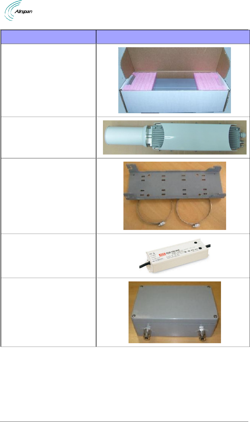
Parts
Images
AirSynergy Unit (with front
mounted antenna) in typical
packing box
AirSynergy unit with Switched
Beam antenna and sunshield
(factory assembled)
Universal mounting plate and
pole straps
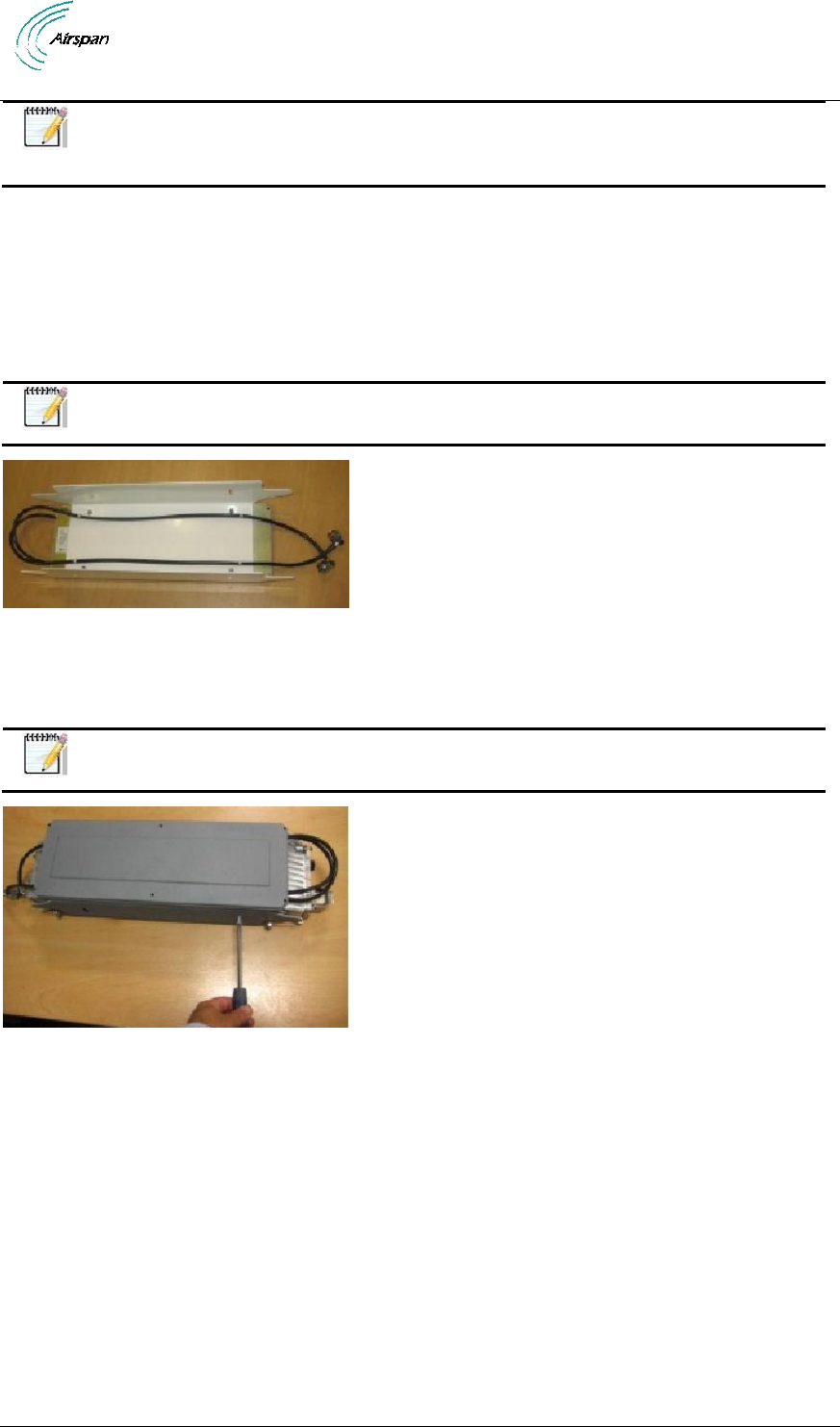
PSU AC/DC (switching power
supply unit)
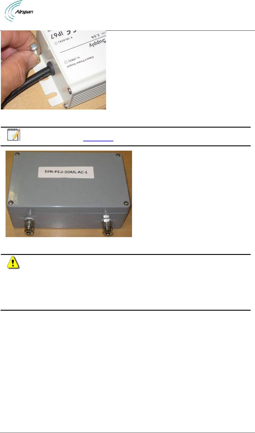
Enclosed PSU (U.S. requirement)
AirSynergy 2000 Installation Guide
Page 27 Commercial in Confidence UGD-D01001 Rev A1
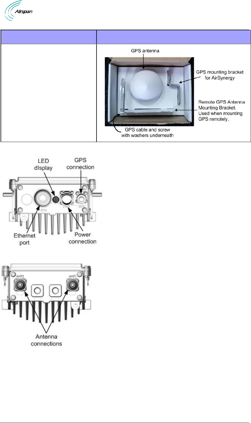
Parts
Images
GPS antenna mounting kit
(boxed)
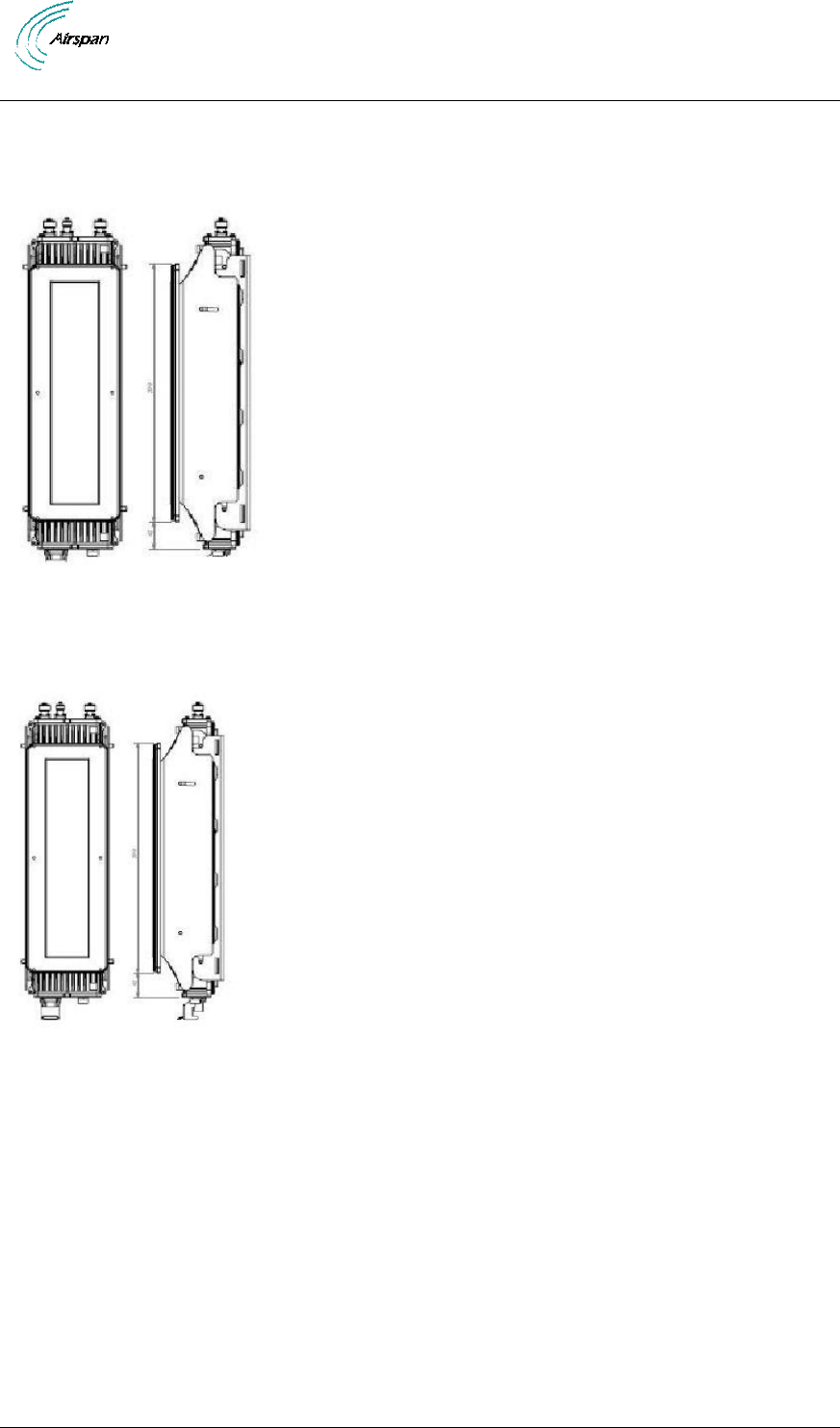
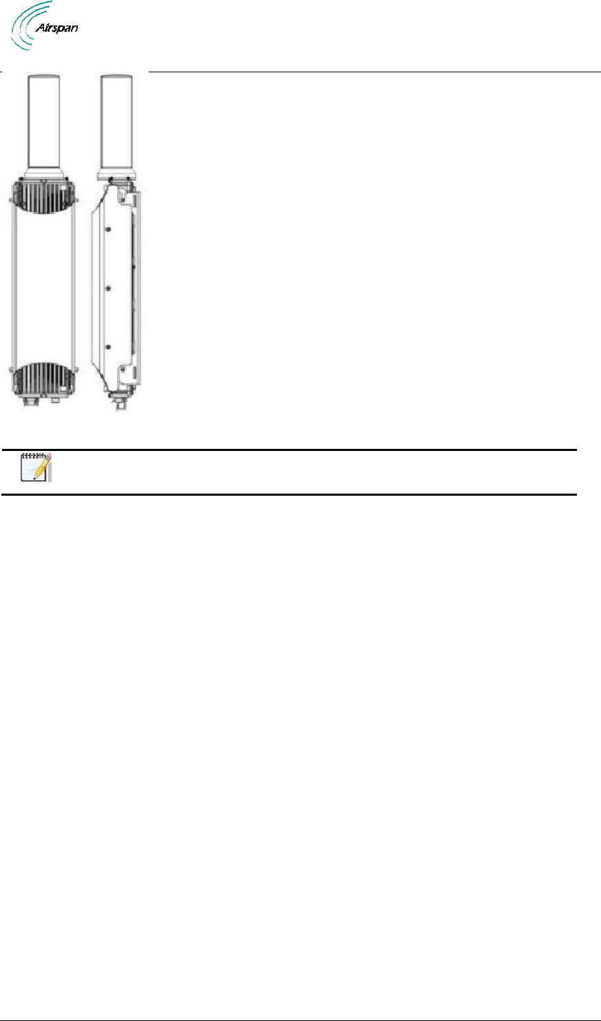
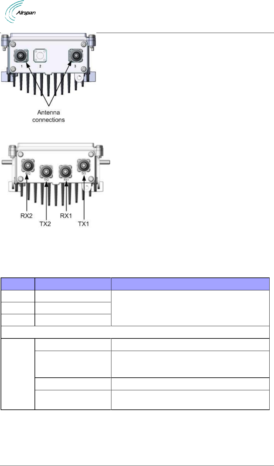
AirSynergy is shown below from the Ethernet termination and RF port end views respectively.
Figure 6 - AirSynergy Unit, bottom termination
Figure 7 - AirSynergy Unit, RF ports, Internal Duplexers
AirSynergy 2000 Installation Guide
Page 28 Commercial in Confidence UGD-D01001 Rev A1
Figure 8 - AirSynergy Unit, RF ports
Figure 9 - AirSynergy Unit, RF ports, External Duplexers
4.2.4 Physical Dimensions
AirSynergy is in an all outdoor enclosure.
Table 11 - AirSynergy physical dimensions
Parameter
Value
Comment
Height
530 mm (20.9 in)
The physical dimensions exclude antenna and
connectors
Width
144 mm (4.49 in)
Depth
106 mm (4.17 in)
Weight
Main unit (Connectorized)
4.65 kg (10.25 lb)
Universal mounting
bracket (Including pole
straps)
925 g (2.04 lb)
Sun-shield
575 g (1.27 lb)
Front mount antenna &
plate
1.35 kg (2.98 lb)
RF Ports for antenna connections are N-Type Female connectors located on the top of the
AirSynergy enclosure.
AirSynergy 2000 Installation Guide
Page 29 Commercial in Confidence UGD-D01001 Rev A1
4.2.5 Environmental
Note: AirSynergy is not meant to be used in a Marine environment.
AirSynergy meets the following environmental requirements:
ETSI EN 300-019-1-4 Operational (non-weather protected equipment)
ETSI EN 300-019-1-1 Storage (weather protected, not temperature controlled
locations)
ETSI EN 300-019-1-2 Transportation
Table 12 - AirSynergy Environment Compliance
Type
Details
Standard Compliance
Operating temperature
-40°C to 55°C
ETSI 300 019 1-4
Operating humidity
5% - 100% non-condensing
ETSI 300 019 1-4
Storage temperature
-40°C to 70°C
N/A
Storage humidity
5% - 100% non-condensing
ETSI 300 019 1-4
Rain and dust ingress
protection
IP66
N/A
Operational altitude
70-106 kPa as well as:
From -60m to 1800m @ 40C
From 1800m to 4000m @ 30C
ETSI 300 019 1-4
Solar radiation
1120 W/m2
ETSI 300 019 1-4
AirSynergy 2000 Installation Guide
Page 30 Commercial in Confidence UGD-D01001 Rev A1
5 Install AirSynergy
Install the AirSynergy eNodeB by pole mount, wall mount, or single point. The AirSynergy unit
can be connected to various types of antennas via standard RF coaxial cables. Antennas should
be positioned with 10 wavelengths horizontal separation to give optimal Downlink and Uplink
MIMO performance.
AirSynergy is normally mounted on a pole (in close proximity to its external antenna when not
using the AirSynergy front mounted Antenna). Take care to install the mounting plate the correct
way up. This is with the slot openings in the bracket at the top edges as shown.
Caution: Proper local rigging and hoisting practices should be followed when
installing the AirSynergy.
5.1 Pole Mount Assembly
The following images show the pole mount assembly.
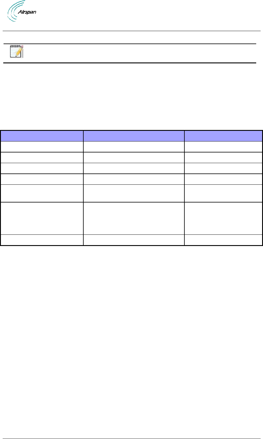
1. Position mounting plate with slots facing up.
Figure 10 - AirSynergy mounting plate and hardware
2. Feed clamp bands through the quick release locking mechanisms and wrap around pole.
Figure 11 - Assemble clamp bands (2 required)
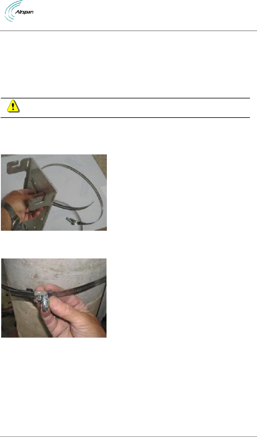
3. Wrap the band to properly fit on the pole. Press down locking mechanism with band
excess fed through the mechanism.
AirSynergy 2000 Installation Guide
Page 31 Commercial in Confidence UGD-D01001 Rev A1
Figure 12 – press down locking mechanism
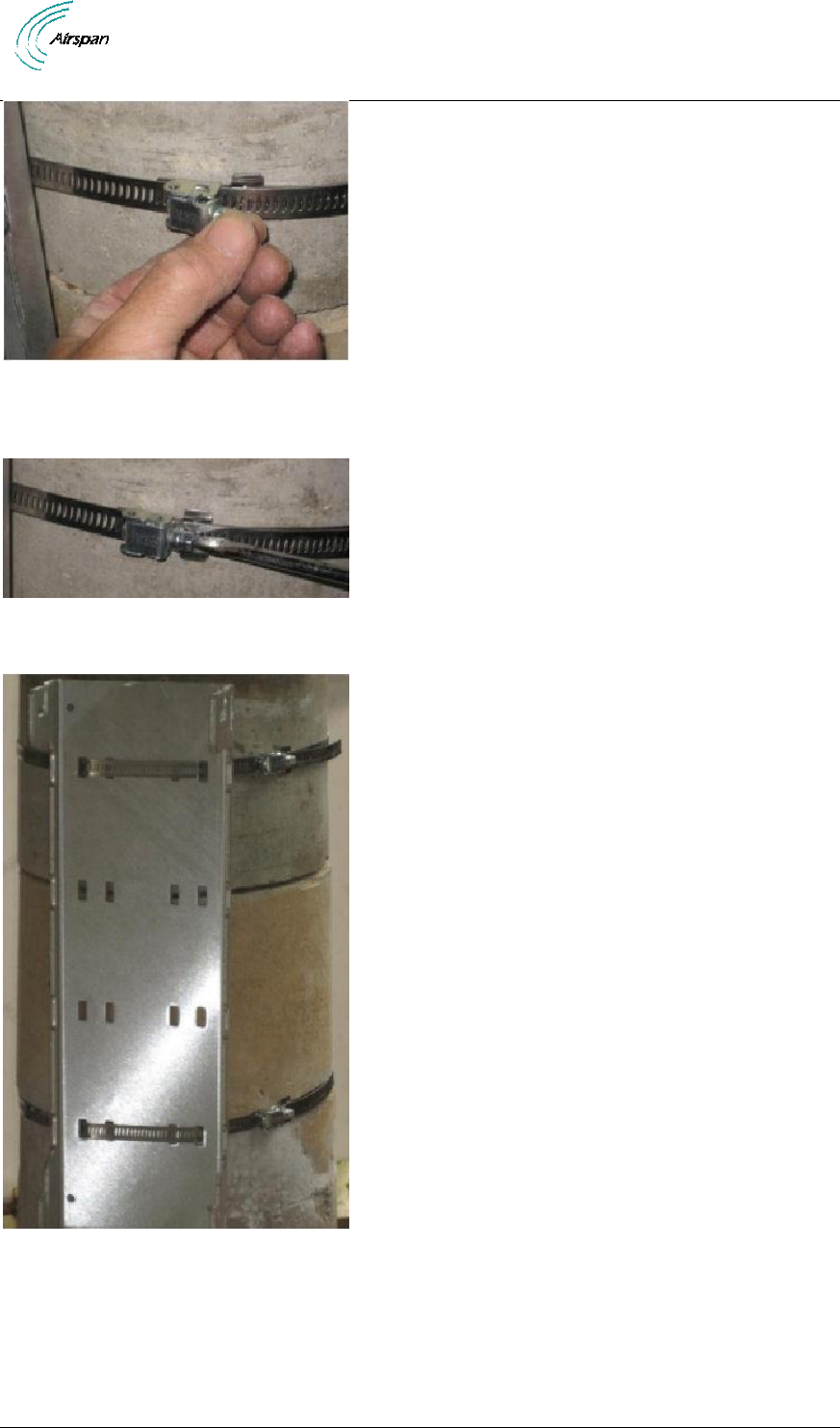
4. Align and position each of the 2 pole clamps. Tighten the clamp bands with large flat
screwdriver in place.
Figure 13 – tighten clamp bands
5. Mounting plate is installed and ready for AirSynergy mounting.
Figure 14 – mounting plate installed on large diameter pole
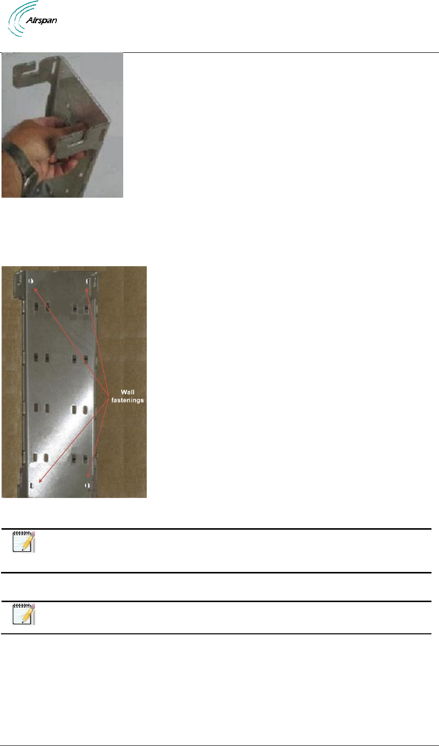
5.2 Wall Mount Assembly
The following images show the wall mount assembly.
1. Position mounting plate against the wall with slots facing up. Be sure to position the wall
mounting plate straight with level mounting to ensure the unit sits evenly.
AirSynergy 2000 Installation Guide
Page 32 Commercial in Confidence UGD-D01001 Rev A1
Figure 15 - positioning wall mounting plate
2. Mark the wall through the holes on the wall mount at the required height.
3. Attach the mounting plate to the wall using wall plugs (x4) rated for at least 8-10 Kg per
fastener.
Figure 16 - wall mounting plate fastened on wall
Note: Wall plugs (x4) and necessary hardware are not supplied by Airspan and
are the responsibility of the installer. Recommended minimum 8mm dia. with
appropriate wall plugs according to field conditions.
5.3 Front Sector Antenna Assembly
Note: The following section is included for spare-parts or replacement assembly
instructions as front mounted antenna variants come factory pre-assembled.
The AirSynergy unit can be used either with a sector antenna mounted directly on the front or with
a remotely attached antenna. The following describes the installation procedure for the front
mounted antenna.
For installation of a remotely mounted antenna follow the antenna manufacturer’s instructions and
connect the antenna to the AirSynergy using the appropriate cables. (Weather-proofed N-type
Heliax RF cables (ordered separately).
AirSynergy 2000 Installation Guide
Page 33 Commercial in Confidence UGD-D01001 Rev A1
Note: When a front mounted antenna is not attached to the unit (remote antenna)
a Sun-shield should be attached. Variants utilizing remotely attached antennas
come factory pre-assembled with a sunshield.
To
mount
the
front
antenna,
perform
the
following:
1. Fit the antenna to the (antenna) mounting plate. The four (4) studs on the back of the
antenna pass through the front face of the mounting plate and are secured with the 4 sets
of M4 nuts and washers (flat and split) included in the kit. Carefully position the lead RF
cables as shown in the figure below and secure them in place to the eyelets on the back
of the mounting plate with the provided cable ties. The cables are formed with a cross-
over at the bottom.
Note: It is recommended to place some packing material under the unit while
assembling to protect it from scratches.
Figure 17 - attaching front mounted antenna to mounting plate
2. Attach the assembled front mounted antenna with the bracket to the AirSynergy unit
using the M5 SEMs (2 on each side) and connect the RF cables to the N type RF ports
on the top of the AirSynergy.
Note: The plate is mounted with the side slots towards the top so that the
required tilt-down can be set.
Figure 18 – Attaching front mount antenna assembly to AirSynergy
5.4 Connecting GPS Antenna to AirSynergy
The GPS antenna should be installed far from:
High-voltage power cables.
Strong radiation area of any TV transmission stations.
Radiation area of the main lobe of the RF Antenna.
Radiation area of the microwave antenna.
Other areas with inter-frequency interference or strong electromagnetic interference.
Cable Fastening Good Practices:
No more than 5m between cable fastening spaces.
No more than 1m between cable termination and first fastener.
Fastenings should be to a robust construction (i.e. mast pole, unit mount…).
AirSynergy 2000 Installation Guide
Page 34 Commercial in Confidence UGD-D01001 Rev A1
Fasteners should be weather and UV resistant.
Cables should have some slack for thermal expansion/contraction between fastenings.
An 80cm cable (supplied with GPS antenna kit) connects the GPS directly to the AirSynergy
connecter, on the bottom panel. When mounting the GPS antenna remotely from the unit, the
GPS antenna should be used in conjunction with the Remote GPS Antenna Mounting Bracket
(supplied with the GPS antenna kit) and the appropriate length GPS cable RG58 TNC-TNC by
way of TNC connectors.
Note: All cables should be properly secured to prevent undue strain on any of
the cable terminations.
Note: AirSynergy units without a factory assembled Switched Beam Antenna all
require a GPS antenna (unless an alternative synchronization method is used,
such as IEEE1588-2008) which comes in a kit with a mounting bracket and a
80cm cable. A primary consideration for a GPS antenna is a clear view of the sky,
preferably 360 degrees.
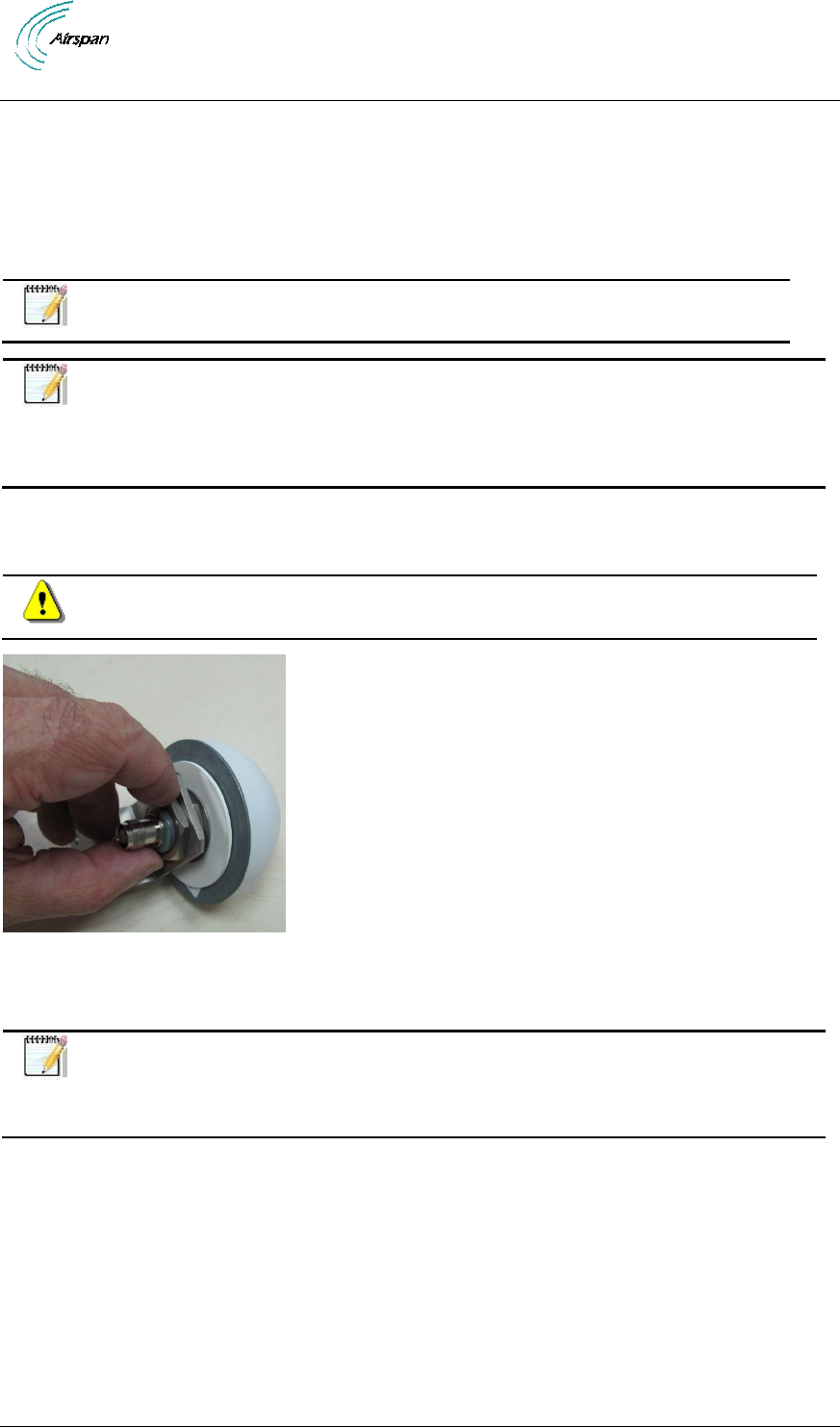
1. Assemble the GPS antenna to the mounting bracket supplied in the GPS antenna
mounting kit. The large nut should be tightened with a pipe wrench.
Caution: Take care not to over tighten the nut so as not to damage the plastic
threads.
Figure 19 - attaching GPS antenna to mounting bracket
2. Attach the TNC to TNC cable from the GPS antenna to the TNC connecter on the bottom
of the AirSynergy unit.
Note: For extreme weather conditions weather-proofing of the TNC connections
is recommended. This is done with a layer of self-amalgamating tape followed by
an over layer of PVC tape. The weather-proofing is best done at this stage to give
easier access to the connections.
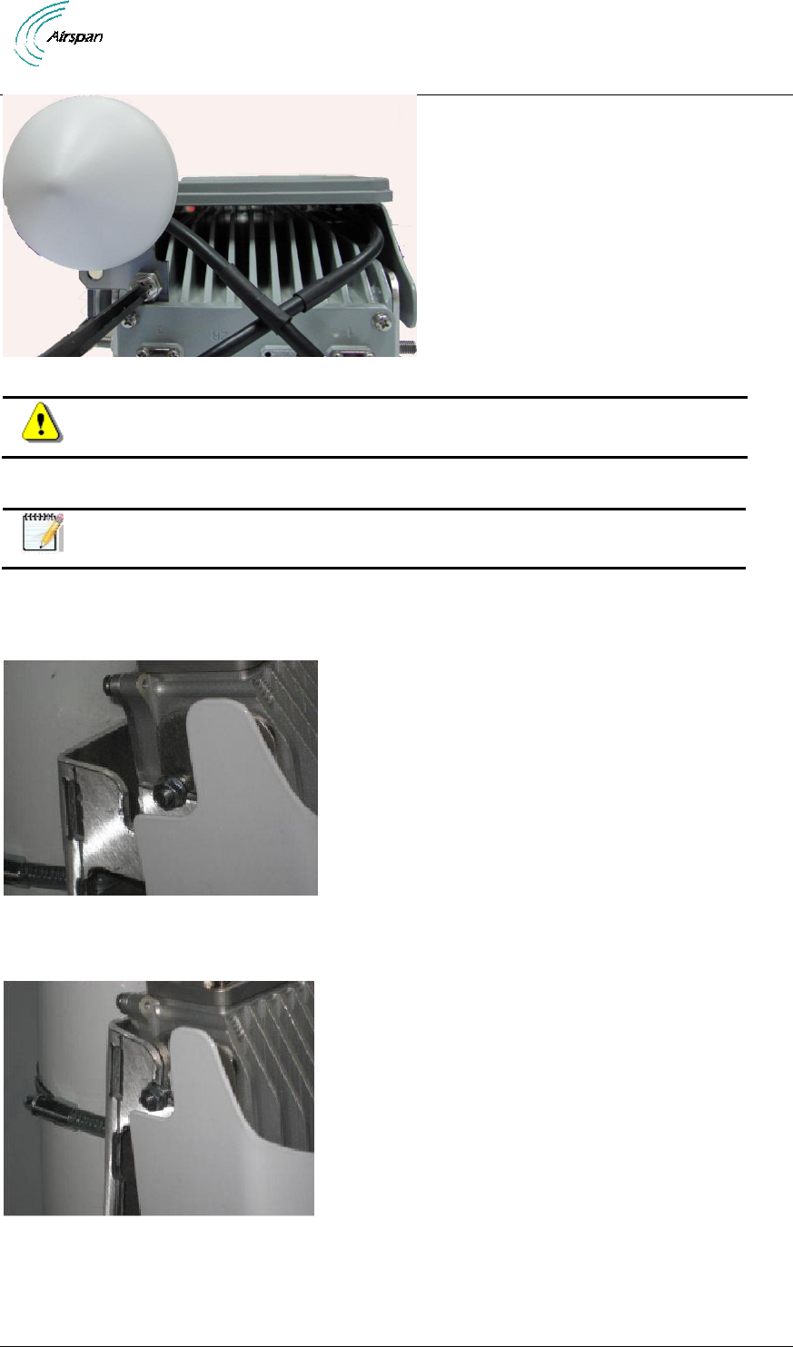
3. Attach the GPS antenna assembly to the body of the AirSynergy unit using the single M6
screw and lock washer provided in the kit. There is a threaded hole on the top corner of
the AirSynergy unit for this purpose.
AirSynergy 2000 Installation Guide
Page 35 Commercial in Confidence UGD-D01001 Rev A1
Figure 20 - Attaching the GPS antenna assembly to AirSynergy
Caution: Attach the GPS bracket in the displayed position only, so as not to
restrict the airflow in any way.
5.5 Securing AirSynergy to the Mounting Plate
Note: the following procedure can also be performed with the Front-Mount
antenna variants exactly as shown below.
To mount AirSynergy to the universal mounting plate, perform the following:
1. Loosely fit the flange nuts on the studs protruding from the sides of the unit.
Figure 21 - Lift unit to top of mounting plate
2. Hook the studs into the top slots of the mounting plate.
Figure 22 - unit engages into slots on the top of mounting plate
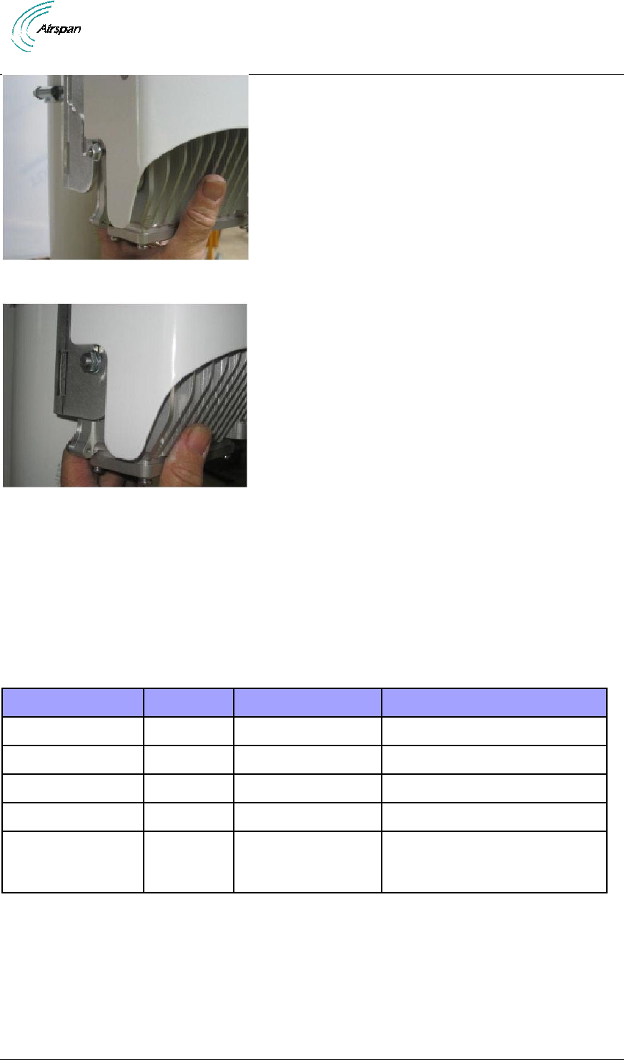
3. With the studs engaged in the top slots raise the unit slightly until the bottom studs also
drop into their respective slots.
AirSynergy 2000 Installation Guide
Page 36 Commercial in Confidence UGD-D01001 Rev A1
Figure 23 - lift the unit until the bottom studs fit into the bottom slots
Figure 24 - AirSynergy unit engaged into the bottom slots
4. Tighten the flange nuts (4 places) to the required degree of down-tilt.
5. Check and tighten all flange nuts.
5.6 LED Display
A single tri-color LED (Green/Red/Orange) appears at the bottom of the unit, providing unit status
indication.
When powering up refer to the following table for indication of current status:
Table 13 - LED Display
Name
Color
Status
Description
Powering Up
Orange
On Continuously
Till the SW starts loading
Software loading
Green
Blinking (3Hz)
While SW is loading
Normal Operation
Green
On Continuously
Normal operation (no alarm)
Major Alarm
Red
Blinking (3Hz)
Service not affected
Critical Alarm
or
Sector OOS
Red
On Continuously
AirSynergy 2000 Installation Guide
Page 37 Commercial in Confidence UGD-D01001 Rev A1
6 Connect and Manage Cables
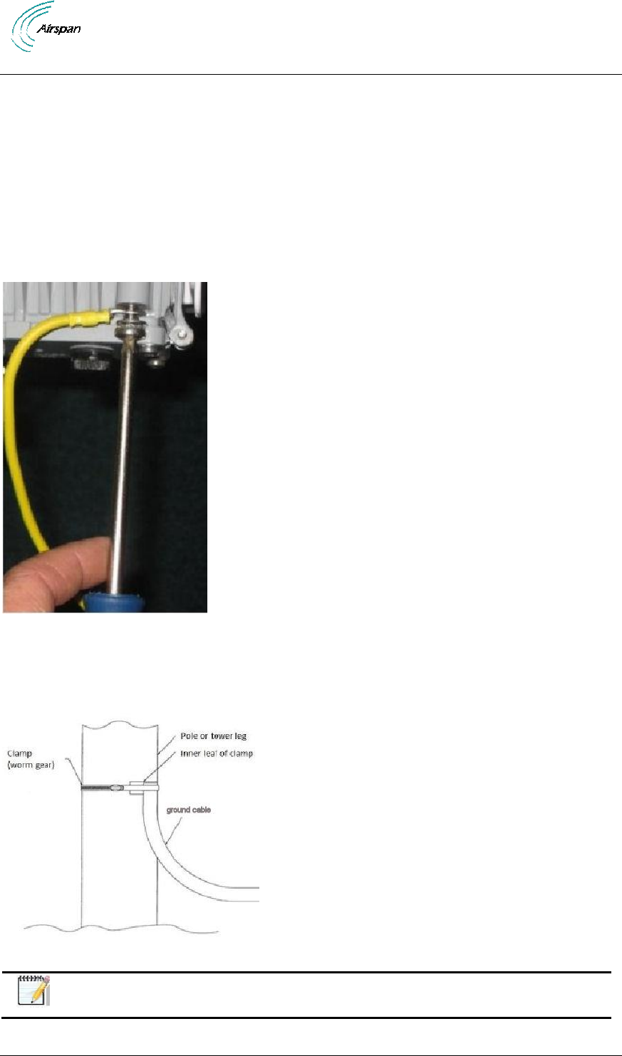
6.1 Connecting the Ground Cable
There is an option to connect a ground cable to the M6 screw threaded connection at the
bottom of the main body casting. This should be connected to a protection ground bar or
clamped directly to the steel structure of the power or pole. This is required in areas of high
lightning activity or when the AirSynergy unit is mounted on high exposed roofs or tower
structures. A direct earth ground connection is required for the surge protection devices inside the
AirSynergy to be effective.
1. Remove grounding screw and slip the ring terminal end of the ground cable onto the
screw prior to re-setting into the threaded hole.
Figure 25 – attaching ground cable to AirSynergy
2. Connect the ground cable to the to the protection ground bar using a suitable crimp lugs.
Alternatively use a clamp to bond the ground cable to the mounting pole or to the tower
structure.
Figure 26 - attach ground cable to pole
Note: When installing a protection ground take care to use suitable metal
combinations to avoid or minimize galvanic corrosion.
AirSynergy 2000 Installation Guide
Page 38 Commercial in Confidence UGD-D01001 Rev A1
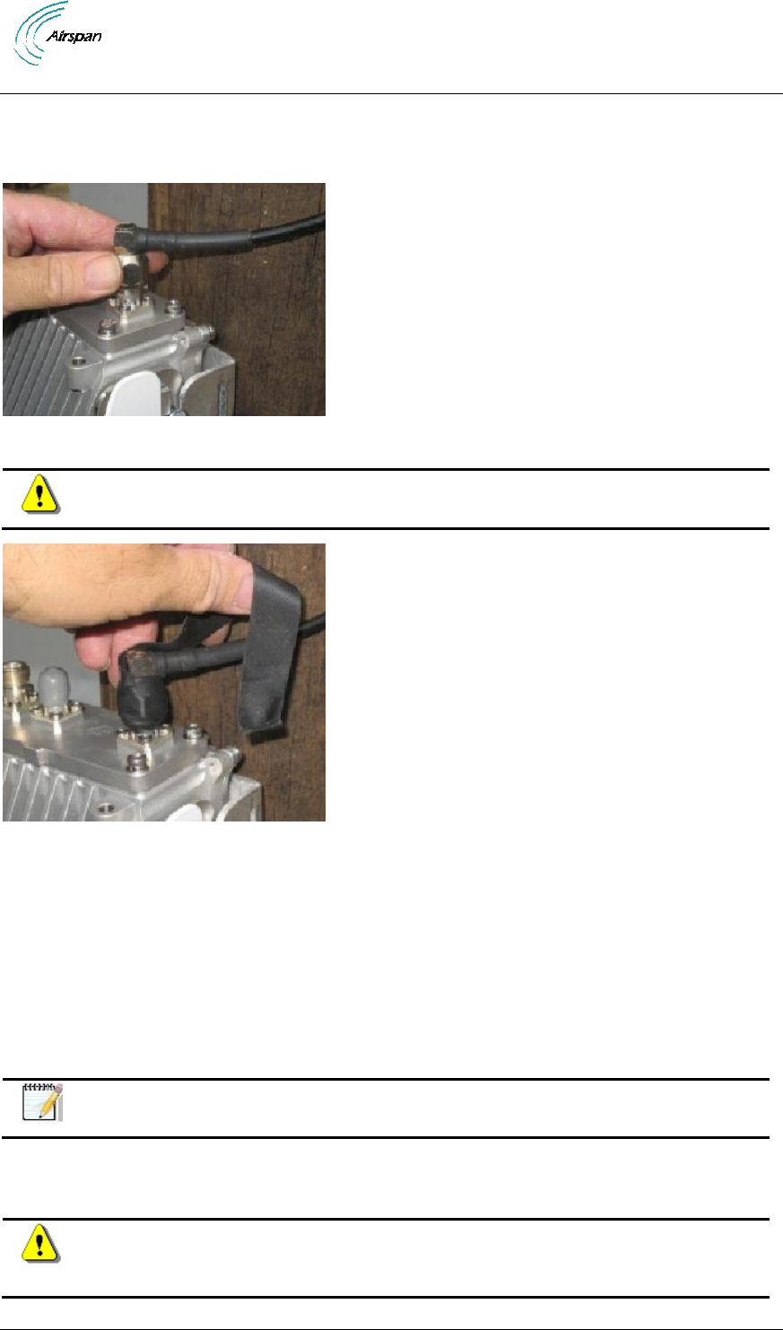
6.2 Connecting RF Jumper Cables to External Antenna
1. Attach, connect and secure the RF cable between the external antenna and the
appropriate RF connection on the top of the unit.
Figure 27 - Connecting RF cable
Caution: Do not over-tighten the RF connector. RF failures can result when the
RF connector is over-tightened.
Figure 28 - weather-proof the connection - external antenna
2. Weather-proofing of the RF N type connections is recommended. This is done with a
layer of self-amalgamating tape followed by an over layer of PVC tape.
3. Verify the RF connector is completely weather-sealed.
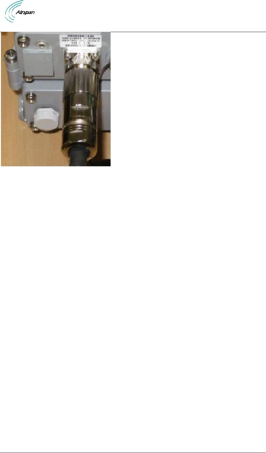
6.3 Connecting the DC Power Cable to AirSynergy
1. Plan the position of the DC power cable run from the AirSynergy unit to the power supply
unit. The DC power cable is offered in various lengths, to fit different deployments.
2. Uncoil the cable and secure the connector just below the AirSynergy unit.
Note: When securing the cable make sure there is no tension on the connector
so that it is easy to disconnect and re-connect for future maintenance actions.
3. Position the pins correctly, the connector is secured to the unit with a locking ring that is
screwed into place. Use firm hand pressure only, the connector has a built in sealing ring.
Caution: The internal plastic parts of the mating connector are keyed. Take care
to align these by visual inspection or by gently rotating the connector body until
the key way sections align and the pins go in before tightening the locking ring.
AirSynergy 2000 Installation Guide
Page 39 Commercial in Confidence UGD-D01001 Rev A1
Figure 29 - attaching power cable to AirSynergy
AirSynergy 2000 Installation Guide
Page 40 Commercial in Confidence UGD-D01001 Rev A1
7 Power System Connection
Hazardous voltage! Before working, ensure that the power is removed from the
power connection cables. When the system is powered on, do not touch the
power terminals.
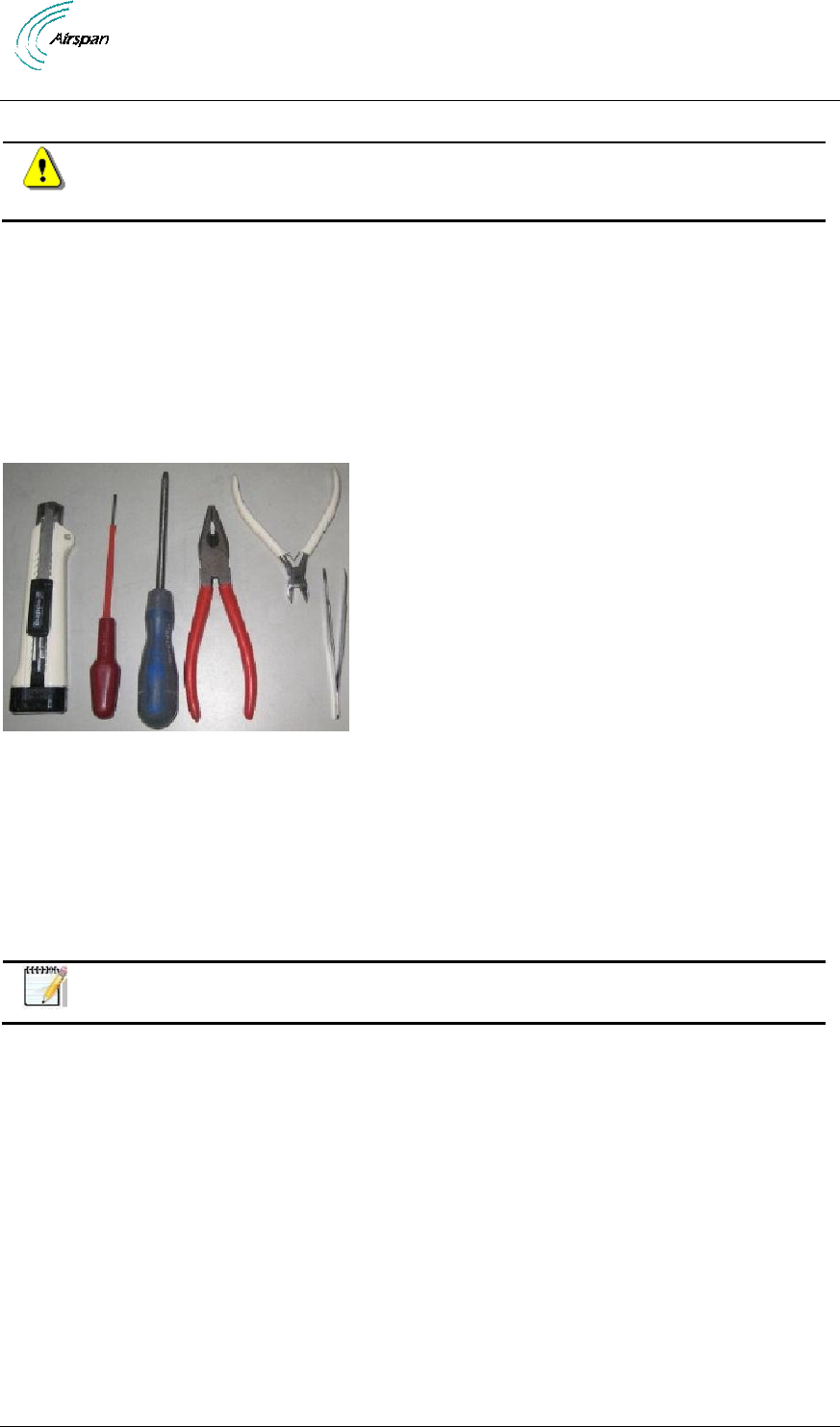
7.1 Required Tools
The tools required for the connection of the PSU are:
knife
small flat blade screw driver (electrical insulated shaft recommended)
medium Philips head screwdriver
pliers
small side cutters
tweezers (or fine blade long nose pliers)
Figure 30 - required tools
7.2 Cable Connections
7.2.1 DC Power Cable Installation
When the DC power cable is to be passed through glands and/or down the center of a lamp post
or other structure, the DC power cable can be cut leaving sufficient length for ease of termination.
With the power supply placed at the selected installation location, trim the cable to the length for
proper installation while allowing sufficient length to strip and prepare the cable ends.
Note: Standard cable supplied is 30m in length, other length options are
available.
AirSynergy 2000 Installation Guide
Page 41 Commercial in Confidence UGD-D01001 Rev A1
Figure 31 - DC Power connection
Figure 32 - Power connection - AirSynergy bottom panel
Advice: It is good practice to label both ends of the cable to identify which
AirSynergy unit it is connected to. This is especially important where numerous
AirSynergy units are installed on the same pole/tower.
Advice: It is good practice to leave a spare loop of cable (approximately 0.5m).
This will allow for easier wiring to the power supply and will allow the cable to be
re-terminated if necessary in the future.
7.2.2 Network Cable Installation
For installations that require a network connection a separate cable must be run to the network
Ethernet switch. The standard length of pre-made cable is 30m. For other lengths up to a
maximum of 100m cables can be made up on site.
Advice: It is good practice to label both ends of the Network cable to identify
which AirSynergy unit it is connected to. This is especially important where
numerous AirSynergy units are installed on the same pole/tower.
Advice: It is good practice to leave a spare loop of network cable (approximately
0.5m). This will allow for easier wiring to the Network switch and will allow the
cable to be re-terminated if necessary in the future.
AirSynergy 2000 Installation Guide
Page 42 Commercial in Confidence UGD-D01001 Rev A1
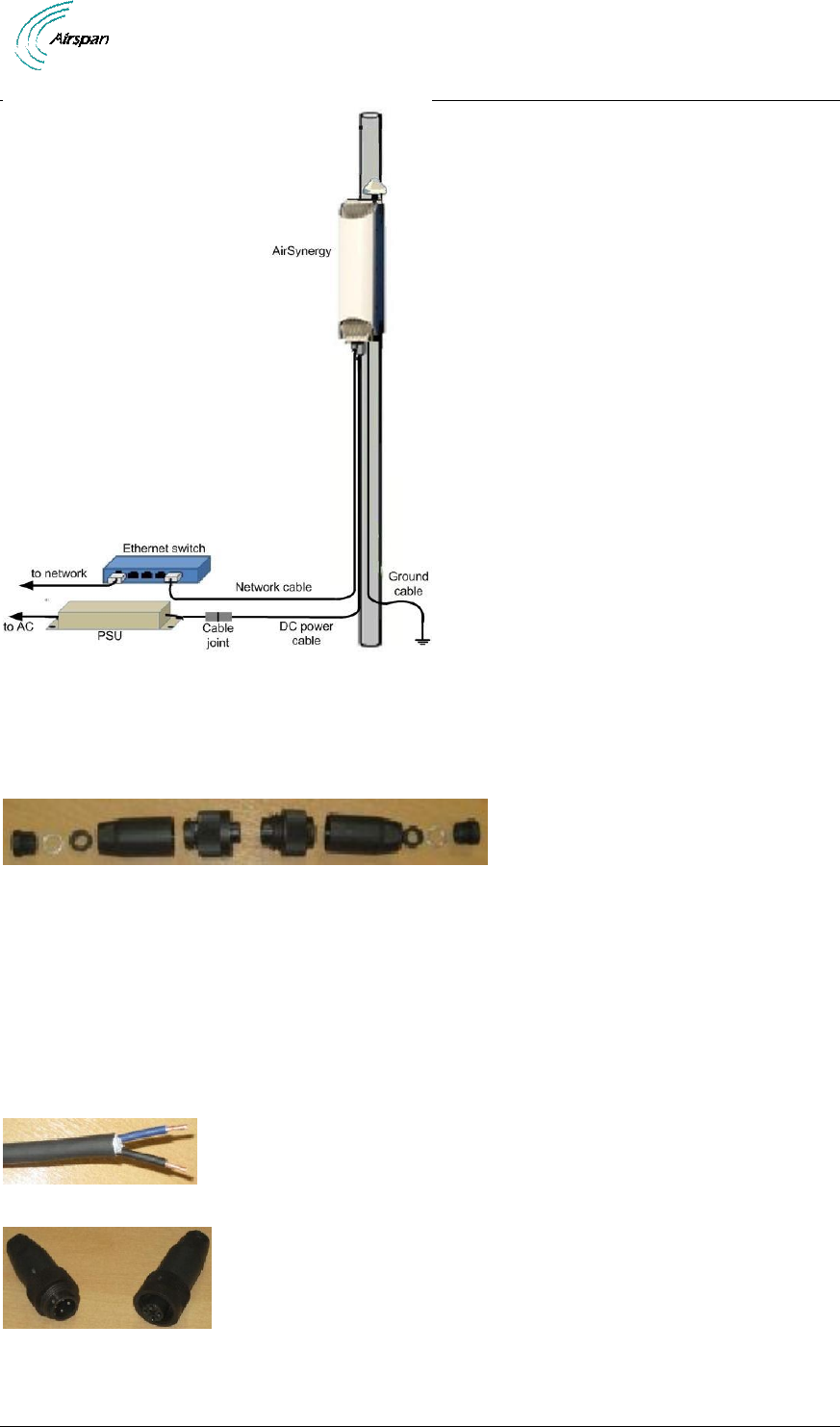
Figure 33 - power and network cable overview
7.3 Wiring DC Power Cable to the PSU
The DC power cable supplied is a standard 30m (98.42 ft) length with the power connector end
for the AirSynergy unit pre-fitted. (Longer lengths are available).
Figure 34 - Waterproof connector exploded view
1. Choose the location PSU and the route of the power cable. Pass the cable through any
building walls or cable entry glands and bring the unterminated end to the location of
the PSU.
2. With the DC power cable from the AirSynergy cut to the required length prepare the
cable to fit the waterproof power connector.
3. Strip back and remove the outer sheath to expose the inner blue and black insulated
wires to a length of 3cm (1.18 in). Then strip back 6mm (0.24 in) of the inner core
insulation.
Figure 35 - power cable preparation
Figure 36 - waterproof connector separated
4. Thread the prepared cable end through the gland, washer, sealing ring and body of the
connector.
AirSynergy 2000 Installation Guide
Page 43 Commercial in Confidence UGD-D01001 Rev A1
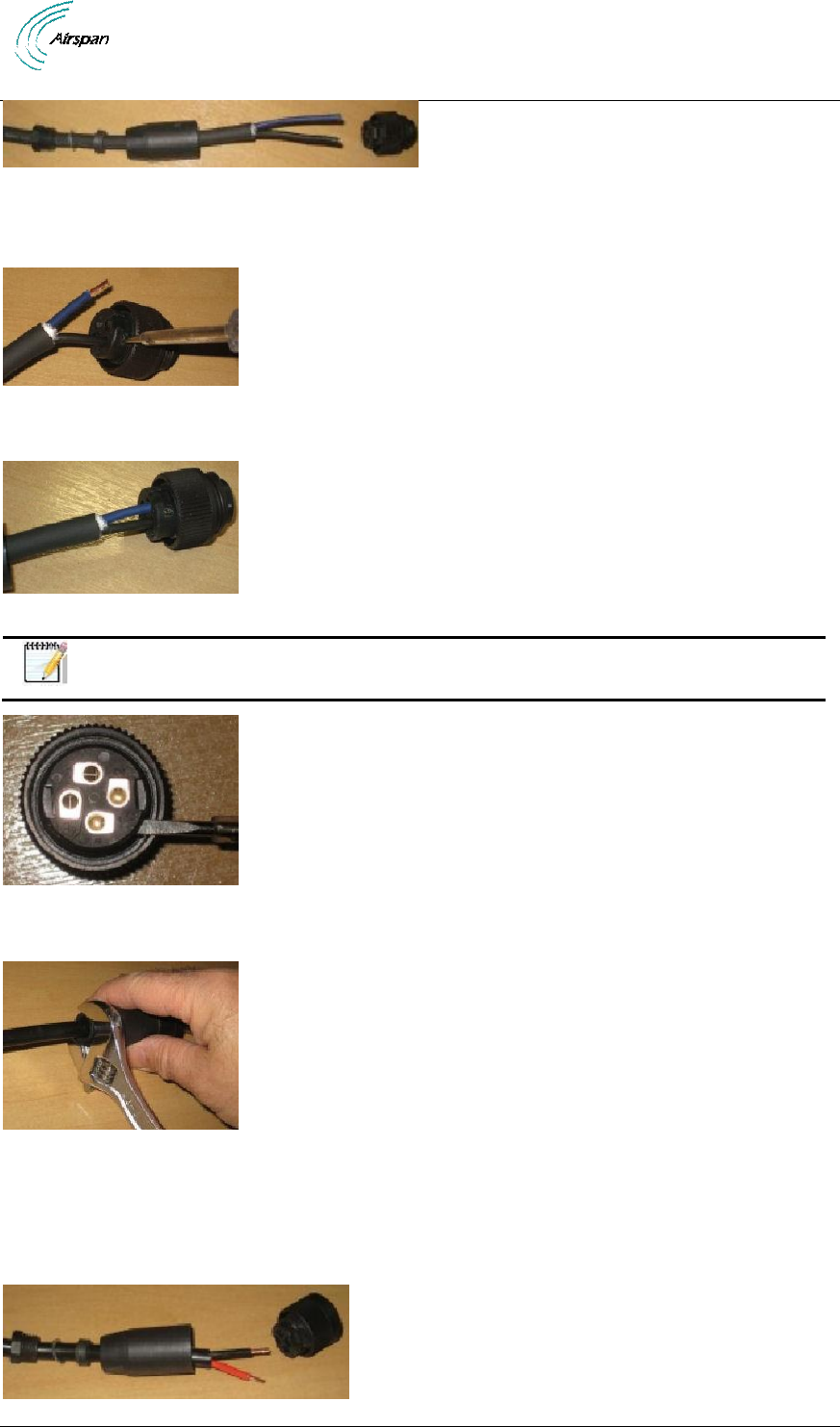
Figure 37 - gland and connector on cable
5. Secure the prepared ends of the power cable into the head part of the connector (male
part with visible pins).
Figure 38 - secure cable to connector
6. Insert and secure the black wire into position 1and the blue wire into position 2.
Figure 39 – power cable wires assembled
Note: Individual connection numbers are marked on each part of the connector.
Figure 40 - numbered connector contacts
7. Assemble the parts of the connector and tighten the gland to provide a waterproof seal.
Figure 41 - assemble and tighten
8. Prepare the ends of the PSU low voltage cable and thread the connector parts over
the cable.
9. Secure the prepared ends of the drop cable into the head part of the connector (female
part).
AirSynergy 2000 Installation Guide
Page 44 Commercial in Confidence UGD-D01001 Rev A1
Figure 42 - PSU cable connector assembly
10. Insert and secure the red wire into position 1 and the black wire into position 2
Figure 43 - PSU wires assembled
11. Assemble the parts of the connector and tighten the gland to provide a waterproof seal.
Figure 44 - assemble and tighten
12. Fasten the 2 parts of the connector together and tighten to make a watertight seal.
Figure 45 - connector assembled and tightened
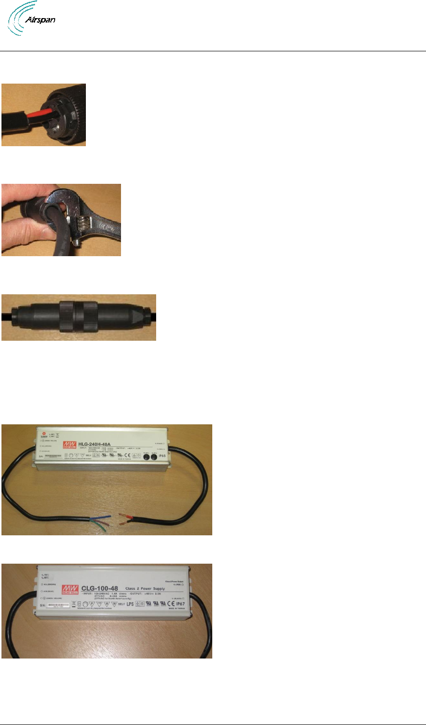
7.4 Connecting the AC/DC PSU to Power Supply
The power (mains) connection should be connected to a fused or protected mains supply (100 to
240 Volts AC). The Brown wire is the Live, the Blue wire is the Neutral and the Green/Yellow wire
is the ground wire.
Figure 46 - High power (240W) PSU – used for dual AirSynergy installations
Figure 47 - Standard power (150W) PSU – used for standard AirSynergy installation
The PSU module can be screwed into position using the self-tapping screws provided (4 places).
AirSynergy 2000 Installation Guide
Page 45 Commercial in Confidence UGD-D01001 Rev A1
Figure 48 - attaching PSU
Note: For USA deployments an alternative PSU and enclosure arrangement is
required – Refer to Appendix D.
Figure 49 - PSU for USA deployment
Caution: Safety - Disconnection of AC supply.
When AirSynergy is connected directly to building or lamp post wiring a
suitably rated and easily accessible disconnect device shall be
incorporated external to the equipment.
When AirSynergy is connected to the AC power supply using a plug and
socket, the socket-outlet shall be installed near the equipment and shall
be easily accessible.

AirSynergy 2000 Installation Guide
Page 46 Commercial in Confidence UGD-D01001 Rev A1
8 Appendix A
Review Job Sheet
The Job Sheet should include the following information:
Pole for installation identified
Position on pole identified
Pole access restrictions (highway regulations, other services on pole, power pole)
Method of reaching pole positions (ladders, Elevated work platform)
AC main fuse block available for PSU (where needed)
Configuration programming details known
Point of connection for Ethernet (if applicable)
All equipment items available at the installation site
o Main AirSynergy unit
o Mounting bracket and pole clamps
o PSU
o Ethernet cable assembly
o GPS Antenna
o GPS antenna installation kit
o Front sector Antenna (if applicable)
o Front sector Antenna mounting bracket ad fixing kit (if applicable)
o External panel antenna (if applicable)
o RF feeder cable tails (if applicable)
Required tools
o Large flat screw driver for pole clamps
o Small flat blade screw driver (insulated shaft recommended)
o Medium Philips head screw driver
o 13mm wrench or small pipe wrench
o 10mm wrench for unit mounting flange nuts
o Knife
o pliers
o Small side cutters
o Tweezers (or fine blade long nose pliers)
o Wire strippers
o Ring terminal crimping tool
o Tilt-meter
Required ancillary equipment
o Laptop PC for initial configuration
o Ethernet cable for temporary connection of the lap top
Other install materials
o Self-amalgamating tape
o Black PVC tape
o Cable ties
Labels
Whether the system is required to be locked to a GPS timing reference..

AirSynergy 2000 Installation Guide
Page 47 Commercial in Confidence UGD-D01001 Rev A1
9 Appendix B - Glossary of Terms - Acronym, Abbreviations &
Definitions
Table 14 - Glossary of Terms
Term
Definition
3GPP
3rd Generation Partnership Project, responsible for LTE
AWGN
Additive White Gaussian Noise is a channel model in which the only impairment
to communication is a linear addition of white noise with a constant spectral
density and a Gaussian distribution of amplitude.
BER
Bit Error Rate
dB
Decibel. A logarithmic unit used to describe a ratio (such as power ratio in radio
telecommunications)
dBm
An abbreviation for the power ratio in decibels (dB) of the measured power
referenced to one milliwatt (mW). It is used as a convenient measure of
absolute power because of its capability to express both very large and very
small values in a short form
eNodeB
Evolved Node B, is the element in E-UTRAN of LTE
ESP
Encapsulating Security Payloads (ESP) provide confidentiality, data-origin
authentication, connectionless integrity, an anti-replay service (a form of partial
sequence integrity), and limited traffic-flow confidentiality
E-UTRAN
Evolved UMTS Terrestrial Radio Access Network, is the air interface of 3GPP's
Long Term Evolution
FDD
Frequency-Division Duplexing. A transceiver mode where the transmitter and
receiver operate at different carrier frequencies
GNSS
Global Navigation Satellite System is a term used to describe a satellite
navigation system with global coverage. There are currently two fully operational
GNSSs – the US GPS and the Russian GLONASS.
HPBW
Half Power BandWidth is the angular separation in an antenna, in which the
magnitude of the radiation pattern decreases by 50% (or -3 dB) from the peak of
the main beam
IPSec
Internet Protocol Security is a protocol suite for securing Internet Protocol (IP)
communications by authenticating and encrypting each IP packet of a
communication session
LED
Light Emitting Diode
LTE
Long Term Evolution
MAC
Medium Access Controller – responsible for several functions such Error
Correction, Packet (De)Multiplexing, etc…
MME
Mobility Management Entity is the key control-node for the LTE access-network.
It is responsible, among other things for idle mode UE tracking and paging
procedure including retransmissions
MTBF
Mean Time Between Failures
OFDMA
Orthogonal Frequency-Division Multiple Access (OFDMA) is a multi-user
version of OFDM digital modulation scheme, used for eNodeB transmissions to
UEs
PDU
Protocol Data Unit
PTP
Precision Time Protocol is used to synchronize clocks throughout a network. In

AirSynergy 2000 Installation Guide
Page 48 Commercial in Confidence UGD-D01001 Rev A1
Term
Definition
this document, PTP is referring to IEEE1588-2008 protocol
ROHS
Restriction Of Hazardous Substances
S-GW
Serving Gateway. A Core entity in the LTE EPC architecture responsible for
routing and forwarding user data packets, while also acting as the mobility
anchor for the user plane during inter-eNodeB handovers and as the anchor for
mobility between LTE and other 3GPP technologies
SBA
Switched Beam Antenna
SC-FDMA
Single-Carrier FDMA is a frequency-division multiple access scheme, dealing
with the assignment of multiple users to a shared communication resource.
Used in LTE for UE transmissions to the eNodeB
SDR
Software Defined Radio
TDD
Time-Division Duplexing. A transceiver mode where the transmitter and receiver
operate on the same carrier frequency
UE
User Equipment. The end user in LTE
WEEE
Waste Electrical and Electronic Equipment

AirSynergy 2000 Installation Guide
Page 49 Commercial in Confidence UGD-D01001 Rev A1
10 Appendix C - Installation Checklist
The Checklist below gives the high-level steps in the Workflow for this procedure. Detach or print
this page to use as a job-aid for completing the actions this procedure requires.
Table 15 - Checklist for Procedure
Procedure
Actions
Outcome
1. Verify Prerequisites
Verify site requirements
Verify safety
requirements
Verify installation
requirements
Verify the tools
Verify parts and kits
All requirements are in
place for a successful
installation
2. Install AirSynergy
universal mounting plate
Install the universal
mounting plate
3. Install AirSynergy on
the mounting plate
4. Connect and manage
cables
Connect power cable
Connect GPS cable
5. Connect power system
Connect Power
Connect the ground
cable
Connect to Ethernet
backhaul
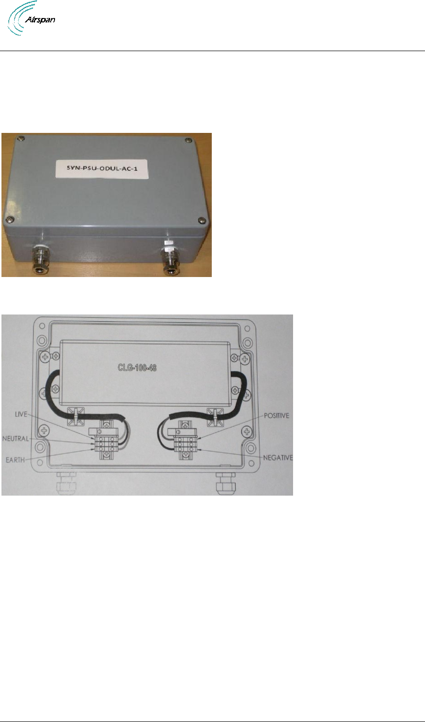
AirSynergy 2000 Installation Guide
Page 50 Commercial in Confidence UGD-D01001 Rev A1
11 Appendix D – PSU for USA
To comply with US regulations that apply to outdoor deployments of mains power supplies, a
special US version of the AirSynergy power supply has been produced with the PSU module and
the electrical connecting blocks enclosed in a small NEMA approved enclosure. The electrical
power cable and 48V power cables are brought through the weatherproof glands provided. This
type of power supply (SYN-PSU-ODUL-AC-3) must be used for all deployments in the USA.
Figure 50 - PSU for USA
1. Remove the top cover of the PSU enclosure.
Figure 51 - Inside PSU with cable terminations
2. Feed the DC power cable through the gland nearest to the low voltage connection and
connect to the terminal strip, observing the correct polarity. (Blue wire in drop cable to
negative terminal and Black wire in the drop cable to positive)
3. Isolate the power supply and pass the power cable through the input gland and
terminate on the connection blocks provided. The termination blocks are clearly labeled
as Live, Neutral and Earth.
4. Choose a suitable position for the PSU enclosure. The PSU enclosure should be
screwed to a firm surface with screws in 4 positions which are only accessible with the
top cover removed.
5. Once the enclosure top cover has been re-fitted (4 screw positions) and the wiring
completed the power can be connected.

AirSynergy 2000 Installation Guide
Page 51 Commercial in Confidence UGD-D01001 Rev A1
12 Appendix E
12.1 Revision History
Revision
Originator
Date
Description
Rev A
M. Falik
09-2013
Initial document
Rev A1
M. Falik
09-2013
“warning” correction
Rev A2
M. Falik
03-2014
TX Power table update
12.2 Contact Information
Customer Service Help-Desk for customer service emergency
Airspan Networks have introduced the Airspan Tracker application to enable prompt and efficient
Customer Support services.
If you do not have an Airspan Tracker account, please obtain login credentials by filling-in the
form in the main page www.airspan.com/Support Register New Account
Worldwide Headquarters:
Airspan Networks Inc.
777, Yamato Road, Suite 310,
Boca Raton, FL 33431, USA
Tel: +1 561 893 8670
93Hwww.airspan.com
Feedback:
To provide feedback on this document, please send comments to the following email
address: 94Hdocumentfeedback@airspan.com