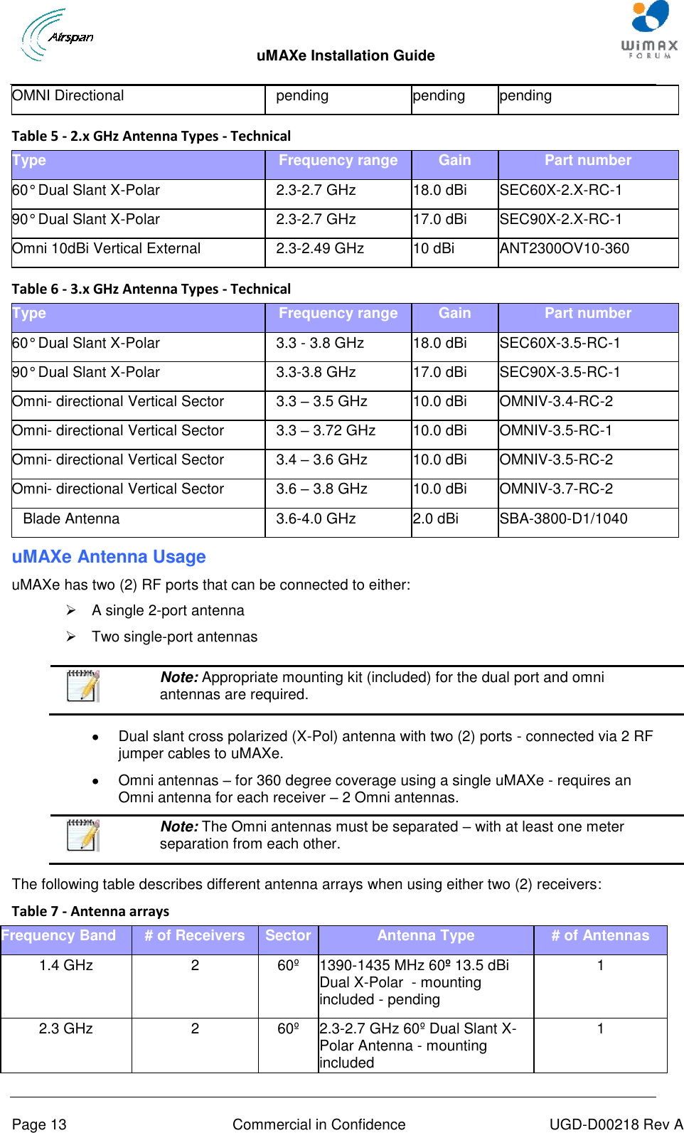
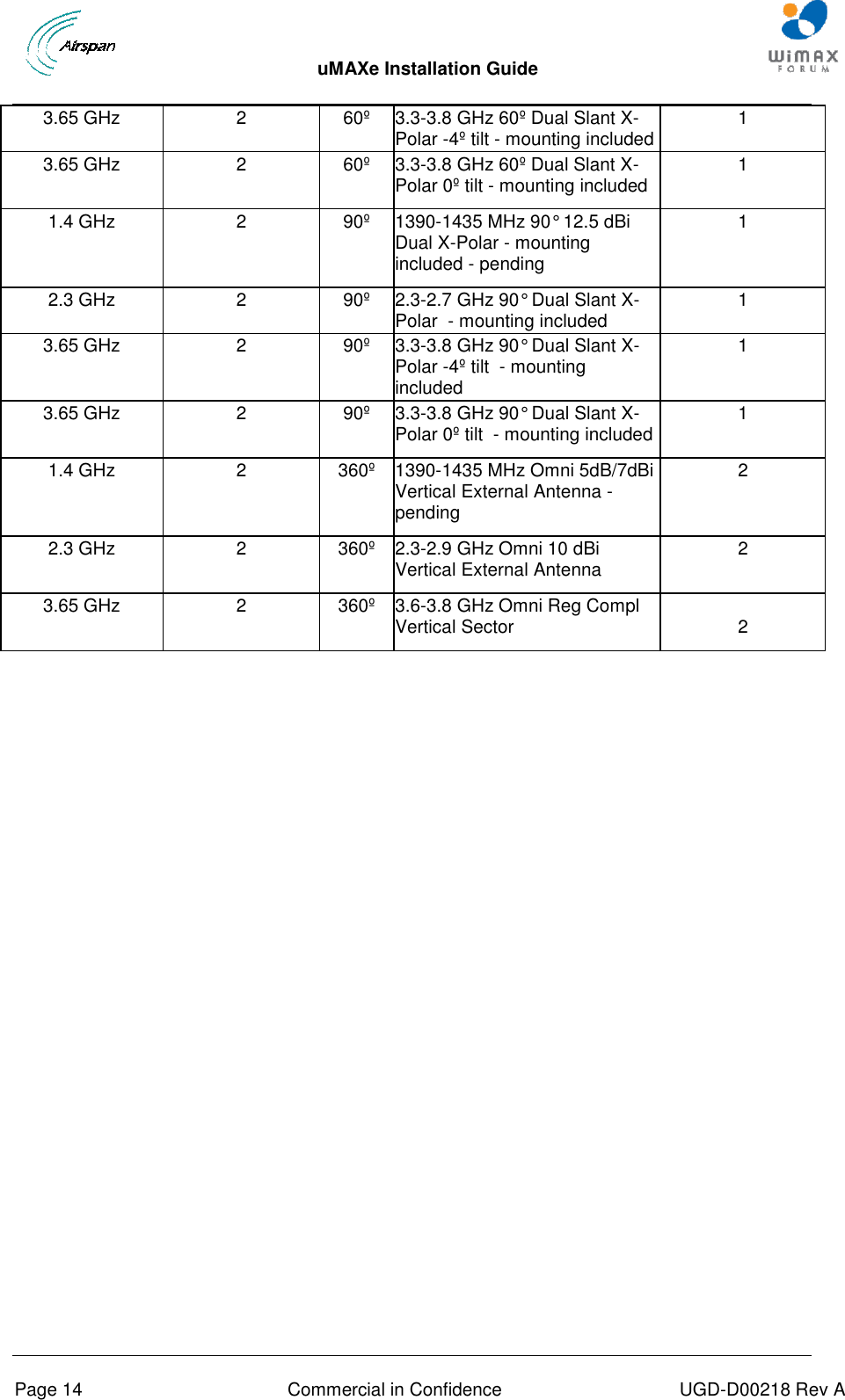
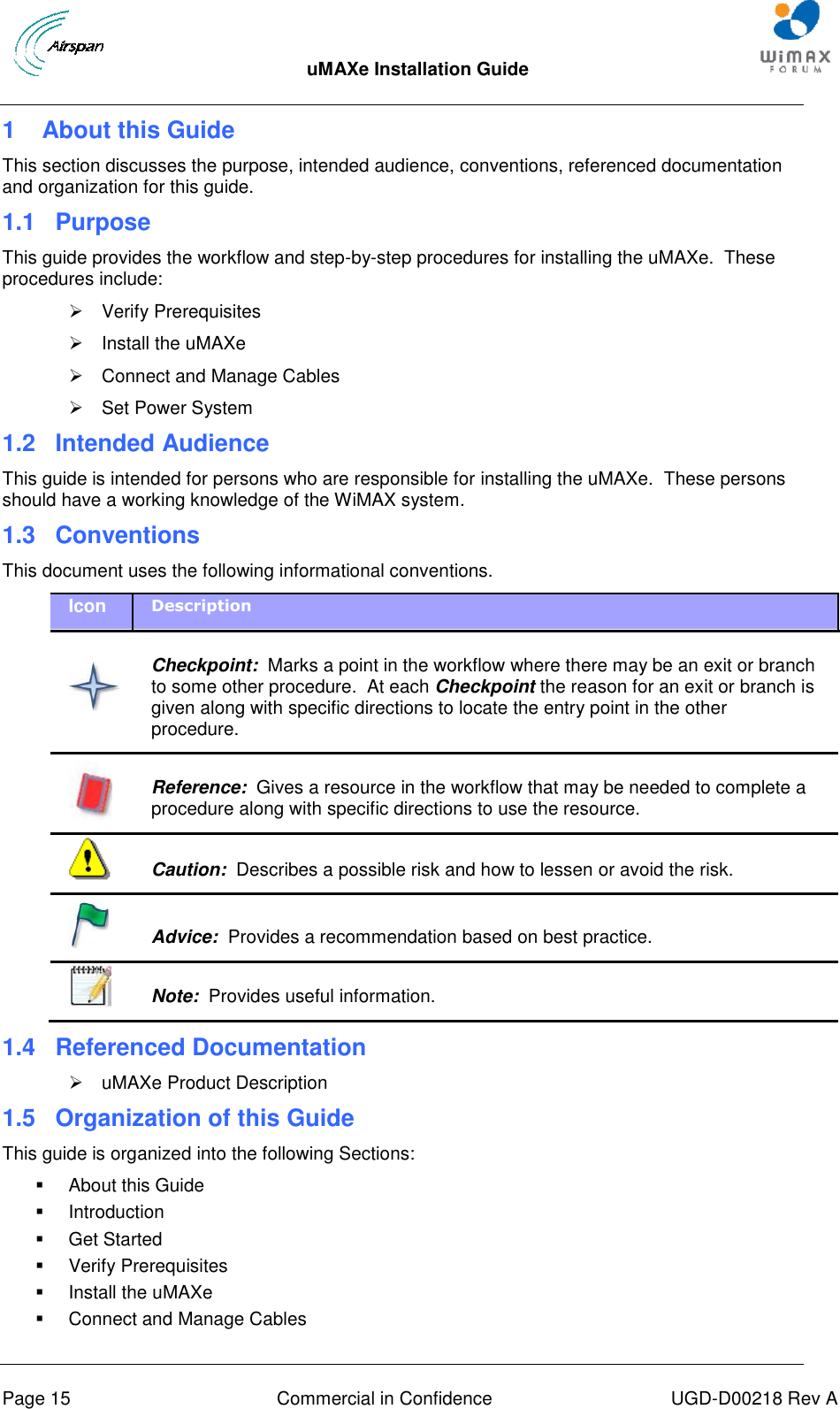
Airspan Networks UMAX3600 WiMAX base station User Manual uMAXe Installation Guide
Airspan Networks Inc WiMAX base station uMAXe Installation Guide
UserManual.wiki
>
Airspan Networks
>
UMAX3600 User Manual
Users manual
Navigation menu
Upload a User Manual
Namespaces
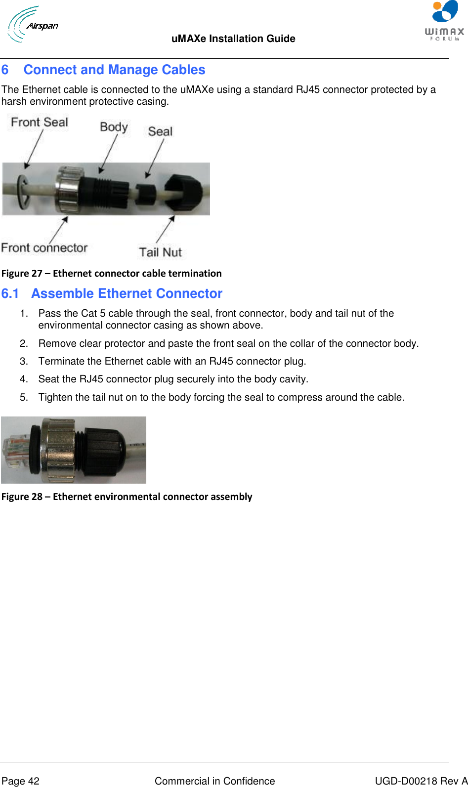
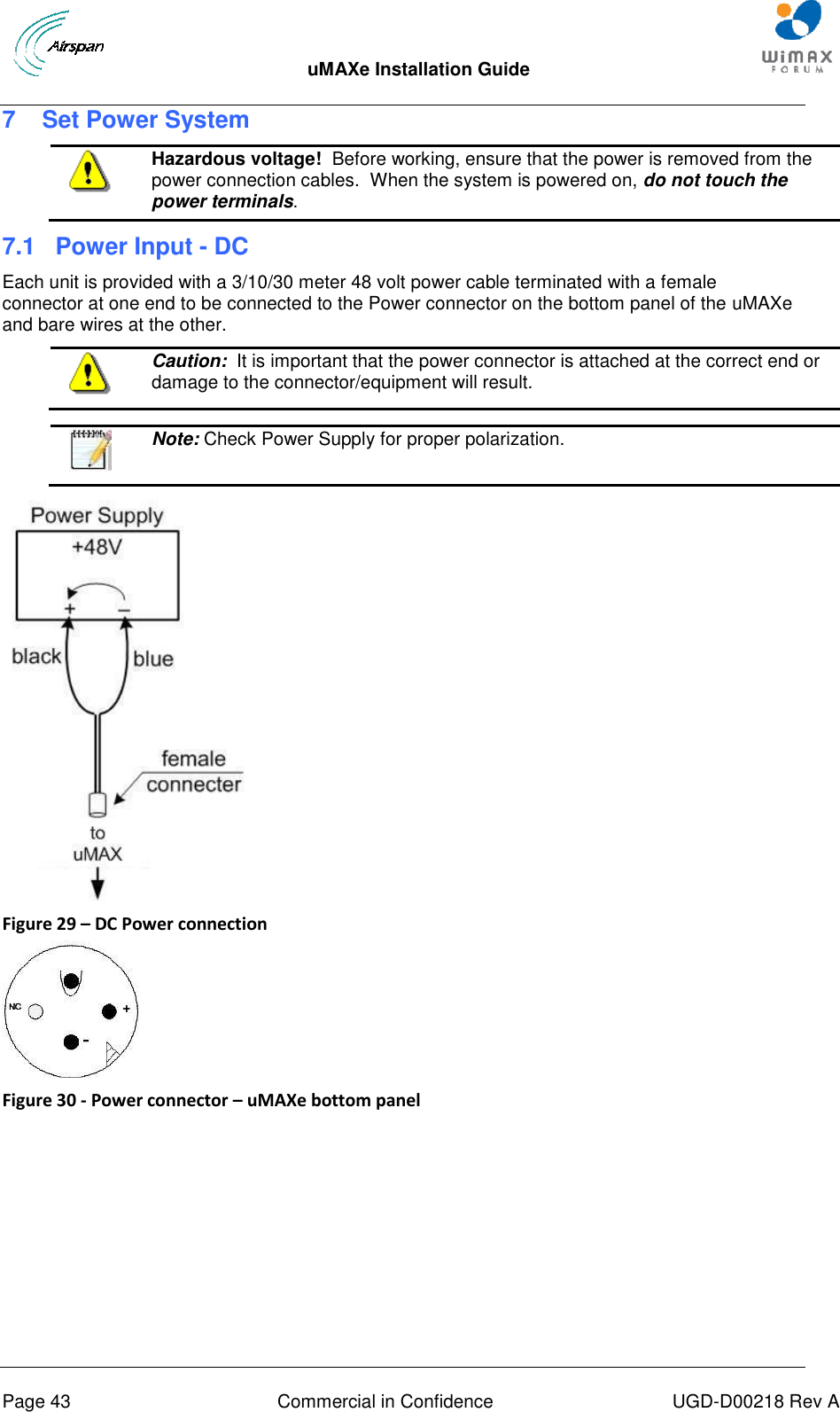
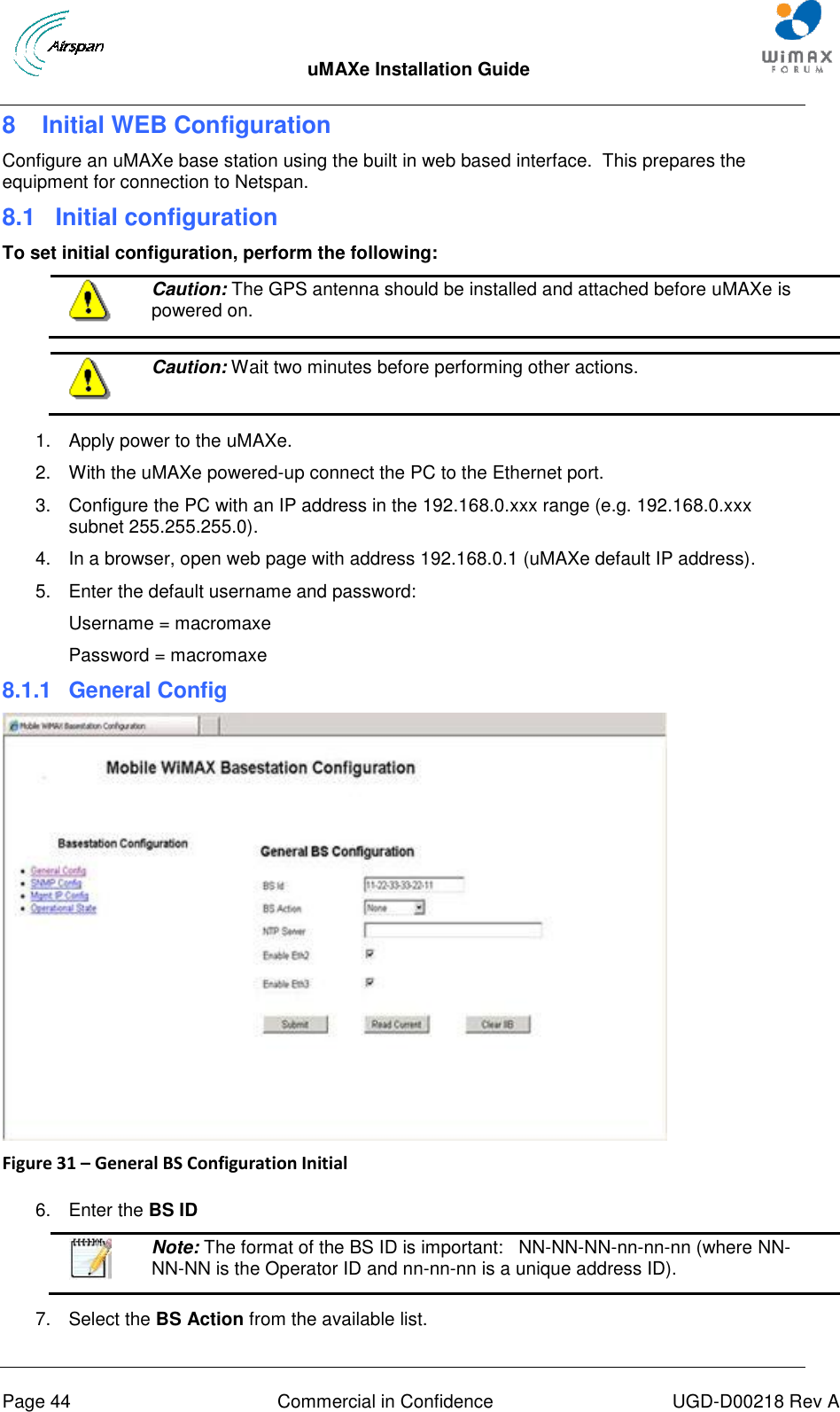
Wiki Guide
HTML
PDF
Info
Views
User Manual
Discussion / Help
Navigation
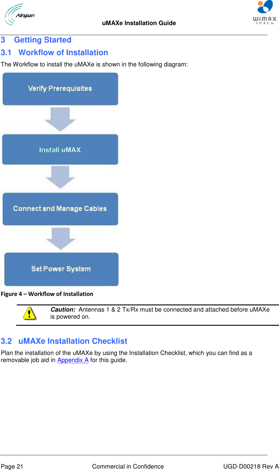
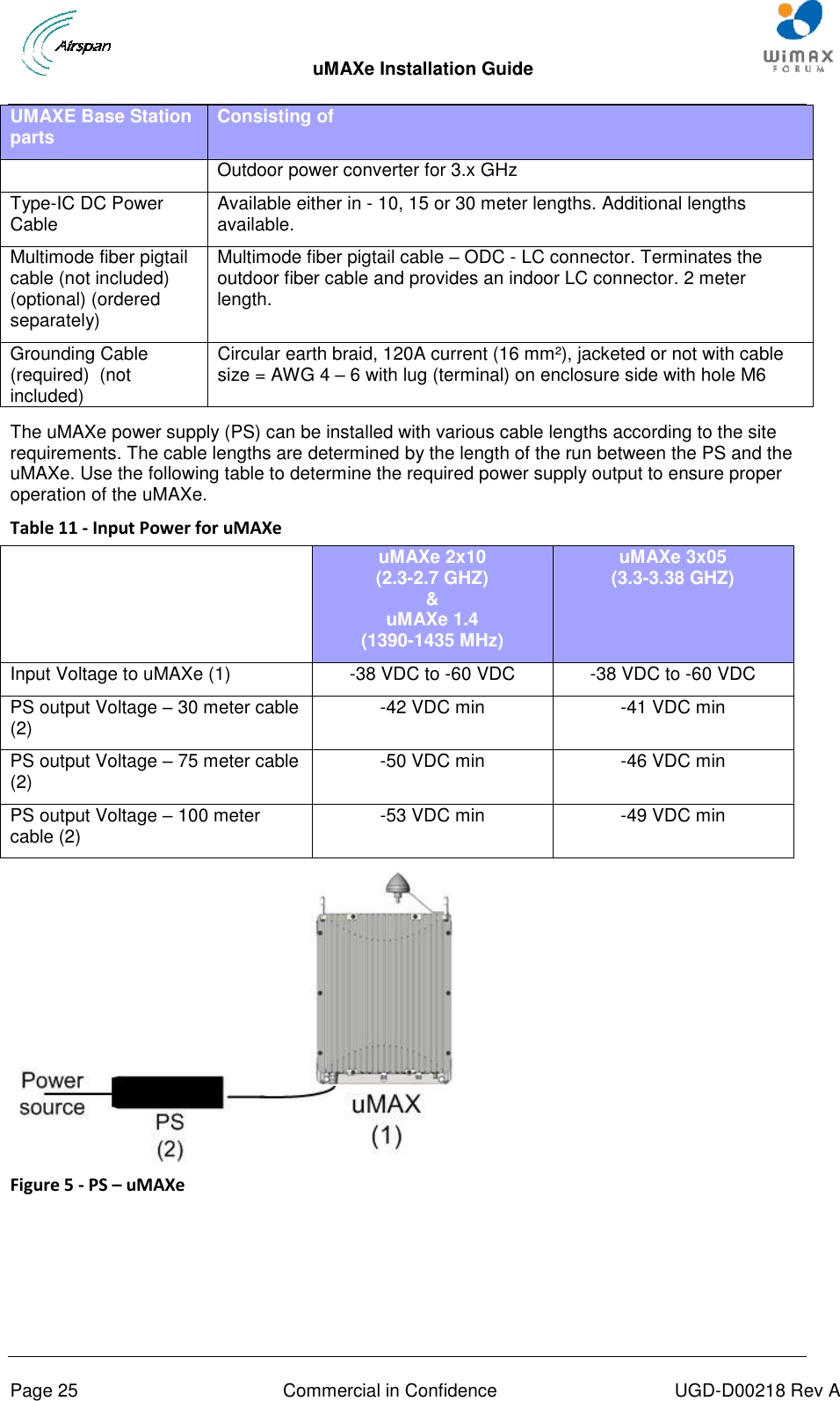
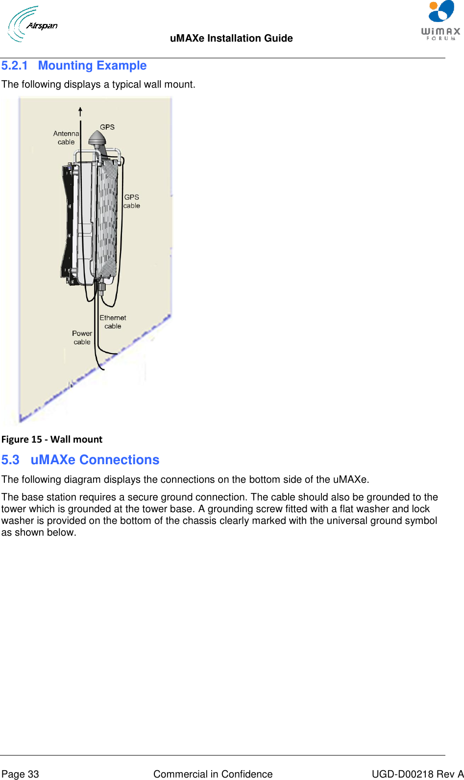
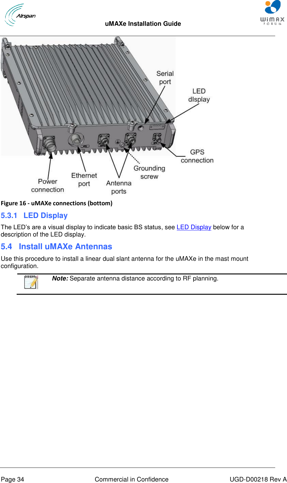
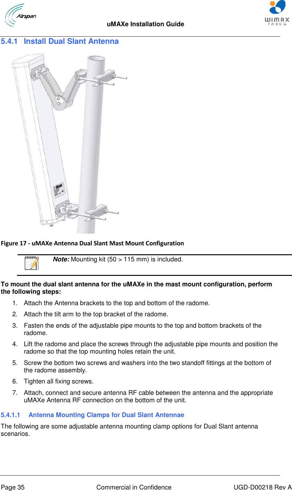
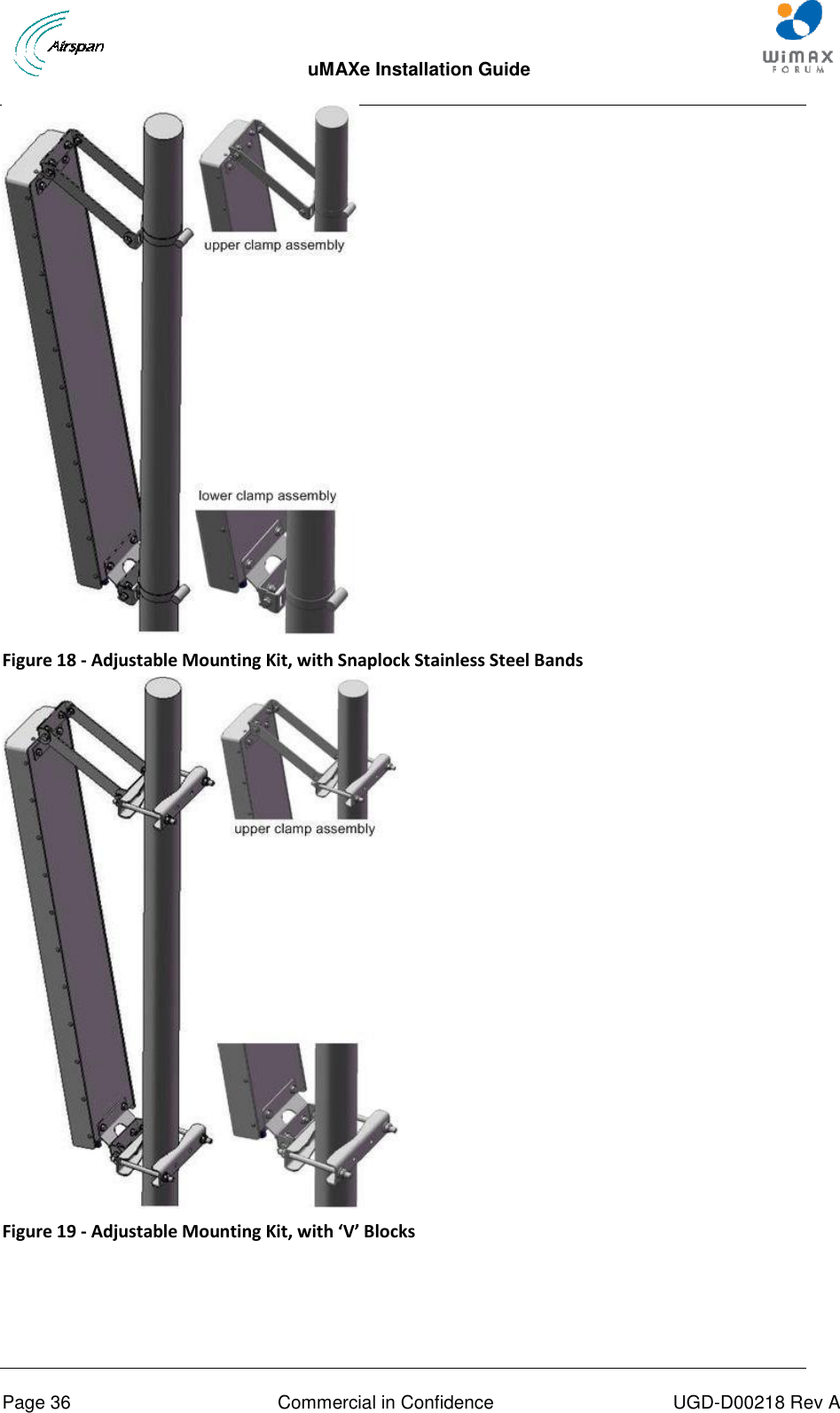
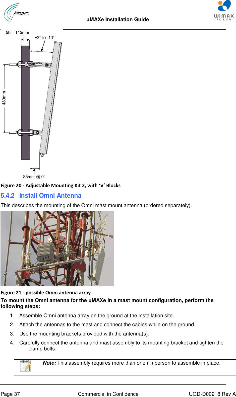
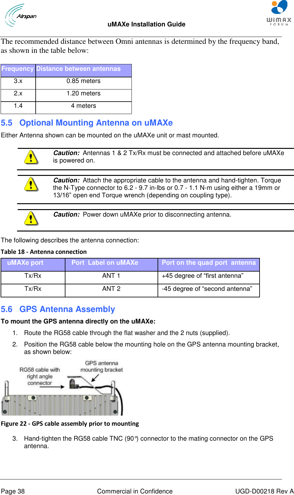
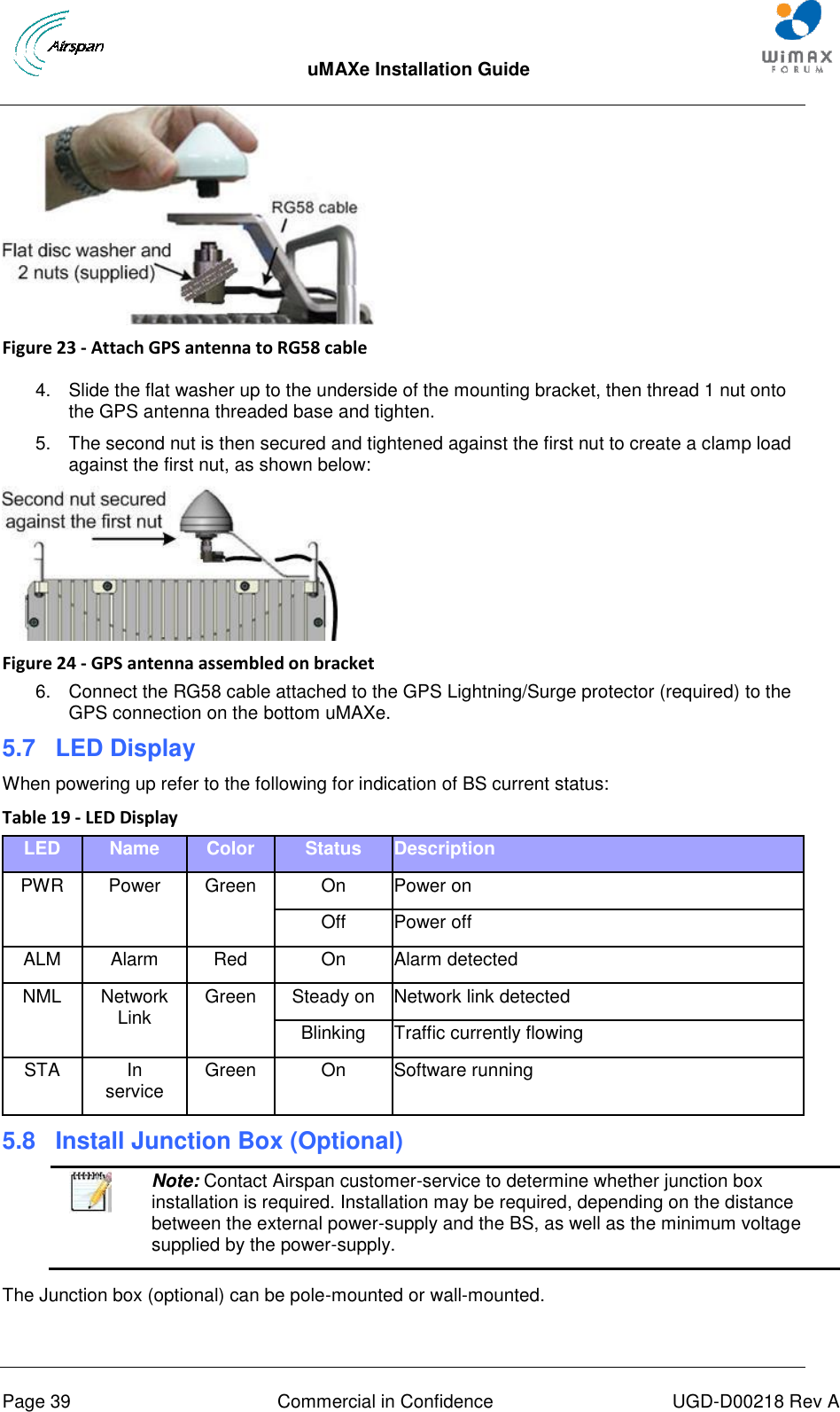
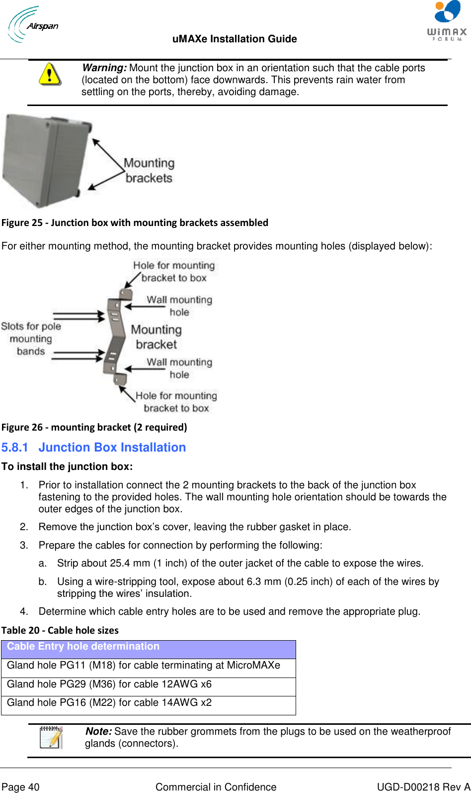
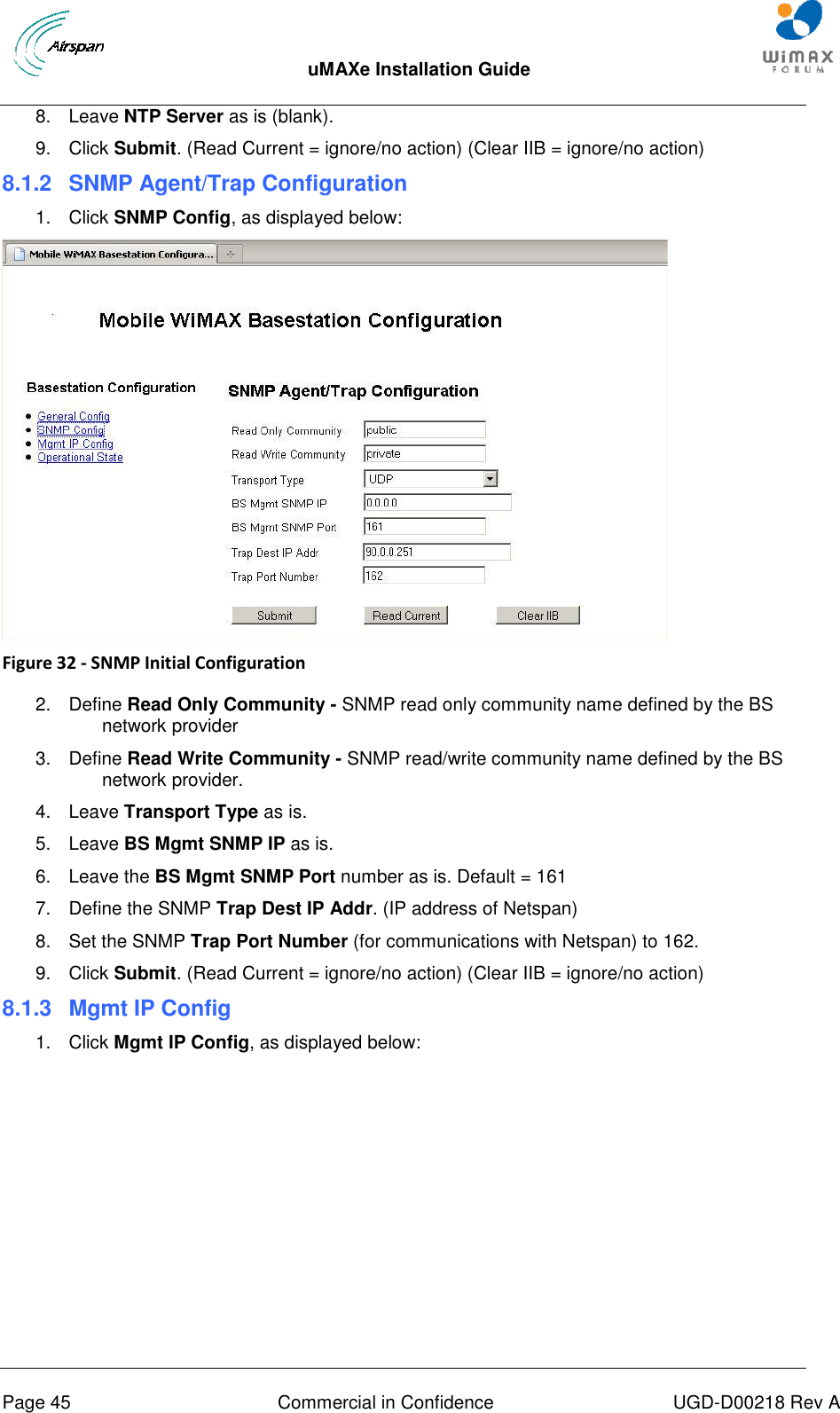
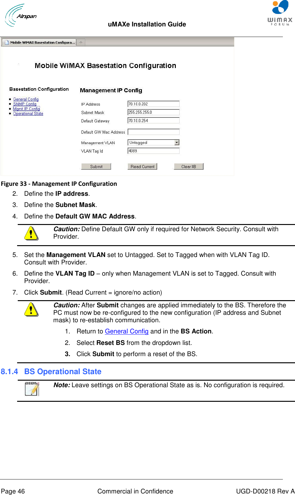
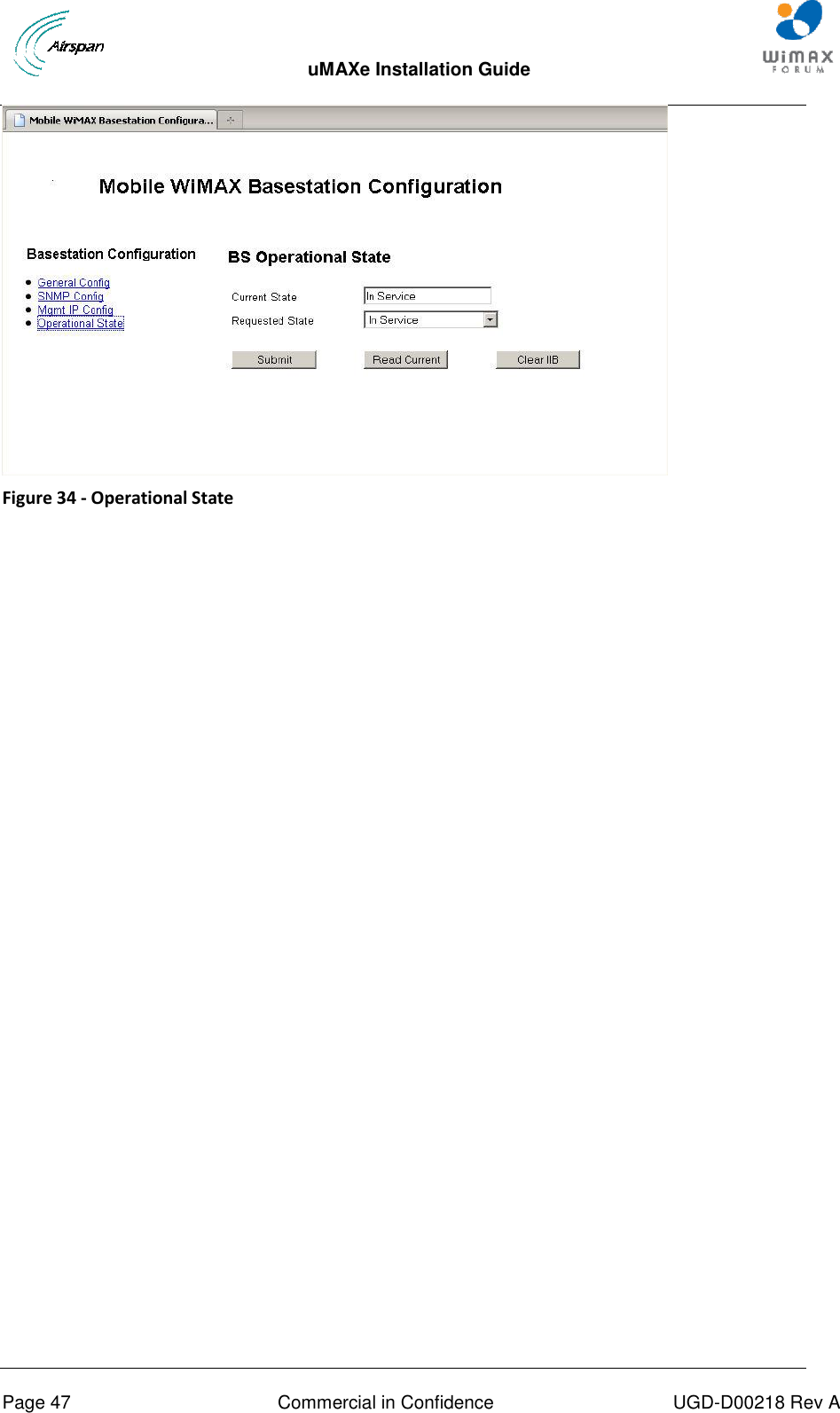
![uMAXe Installation Guide Page 16 Commercial in Confidence UGD-D00218 Rev A Set Power System Appendixes [Review Job Sheet, Securing the cables, Glossary of Terms, Installation Checklist, Contact information and Revision history]](https://usermanual.wiki/Airspan-Networks/UMAX3600/User-Guide-1475344-Page-16.png)