Airtech Information and Communication AQ-40B FM Handheld Transceiver (UHF) User Manual AQ 40B
Airtech Information & Communication Co., Ltd. FM Handheld Transceiver (UHF) AQ 40B
UserManual.wiki
>
Airtech Information and Communication
>
AQ-40B User Manual
>
User Manual 1
Contents
1.
User Manual 1
2.
User Manual 2
User Manual 1
Navigation menu
Upload a User Manual
Namespaces
Wiki Guide
HTML
PDF
Info
Views
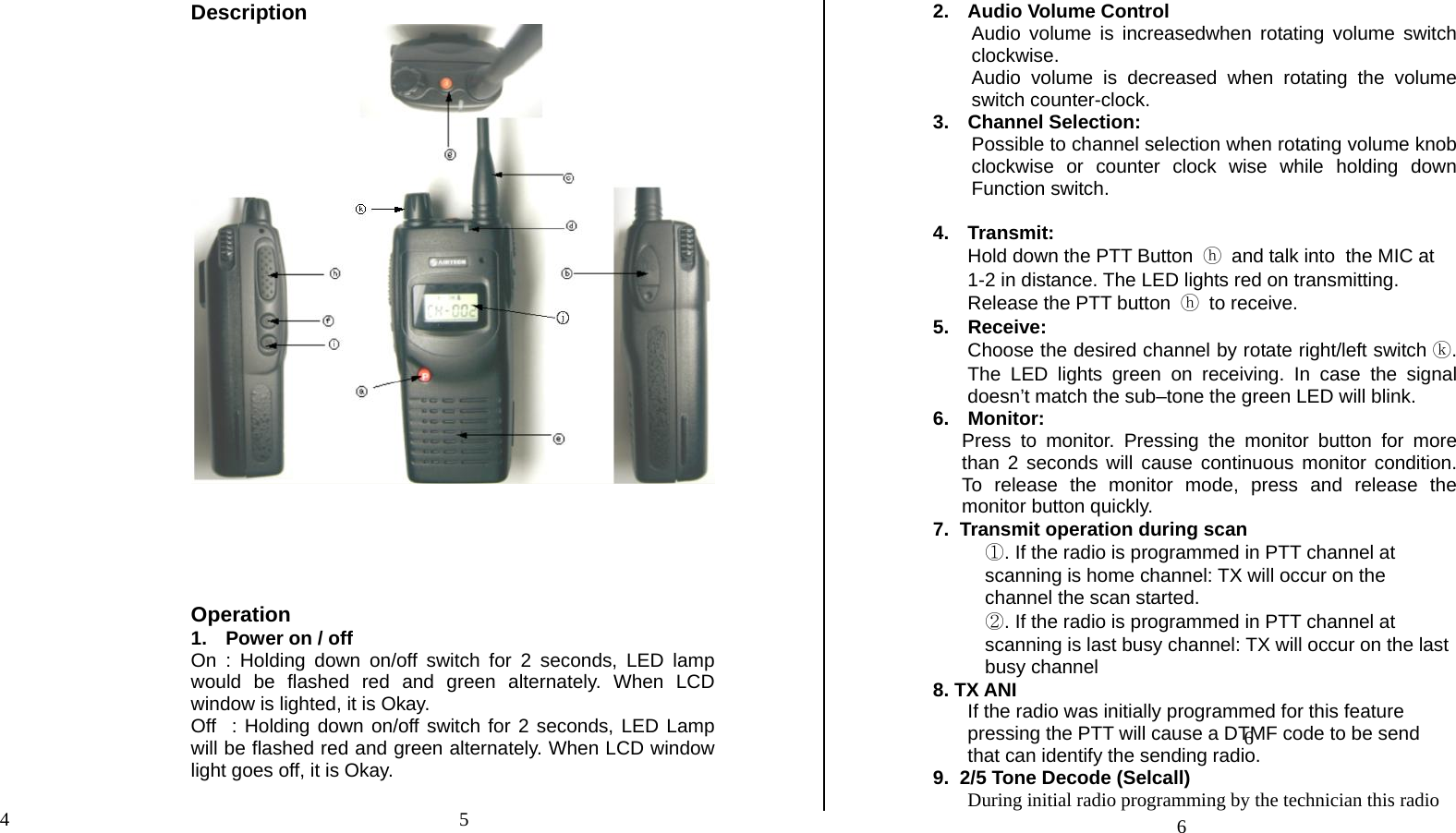
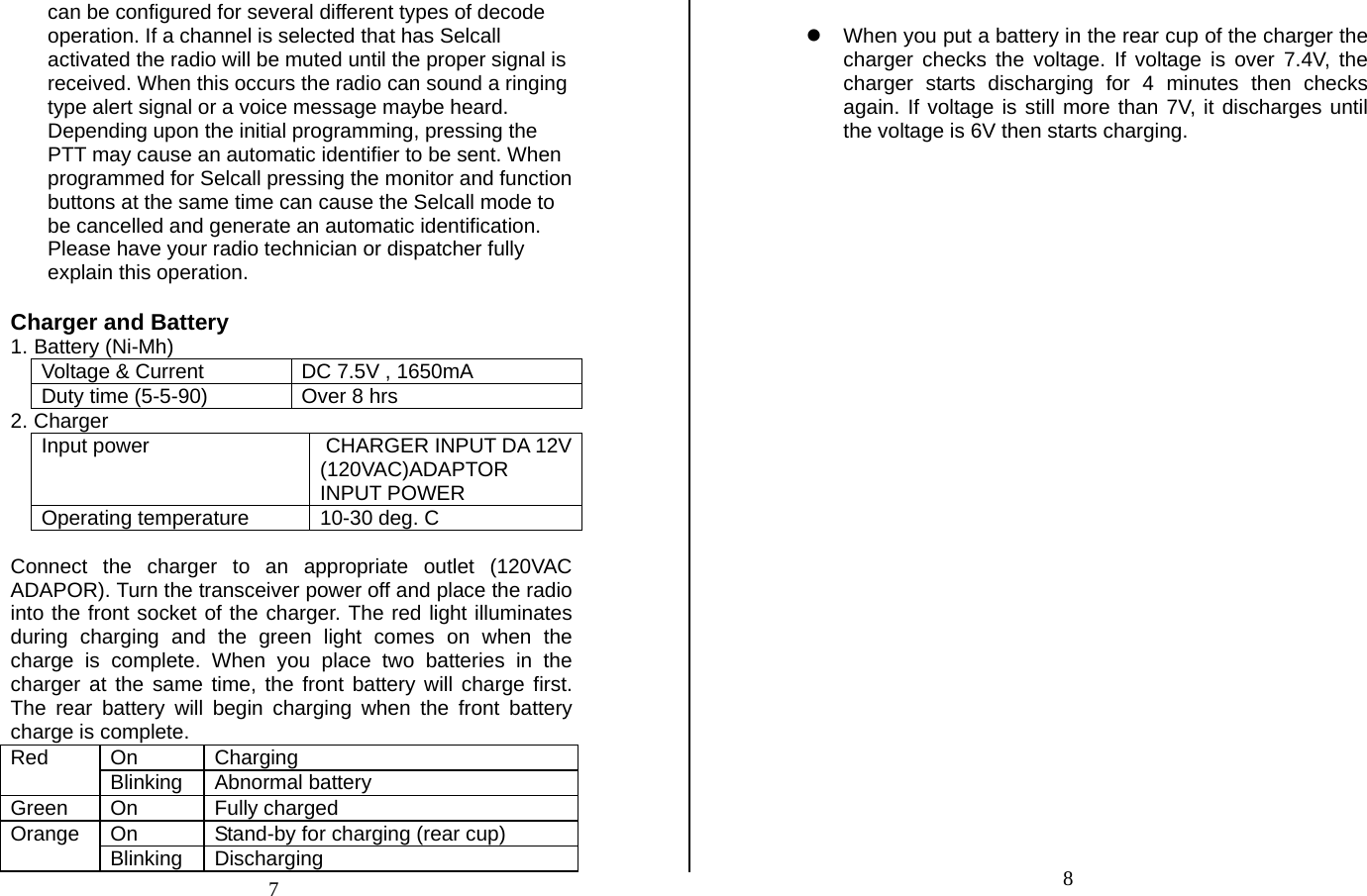
User Manual
Discussion / Help
Navigation