Alarm Controls LNB 6 Basic Wiring Diagram W KP 100 Keypad
User Manual: Alarm Controls Basic Wiring Diagram LNB-6 w KP-100 Keypad Wiring Diagrams and Instructions
Open the PDF directly: View PDF ![]() .
.
Page Count: 1
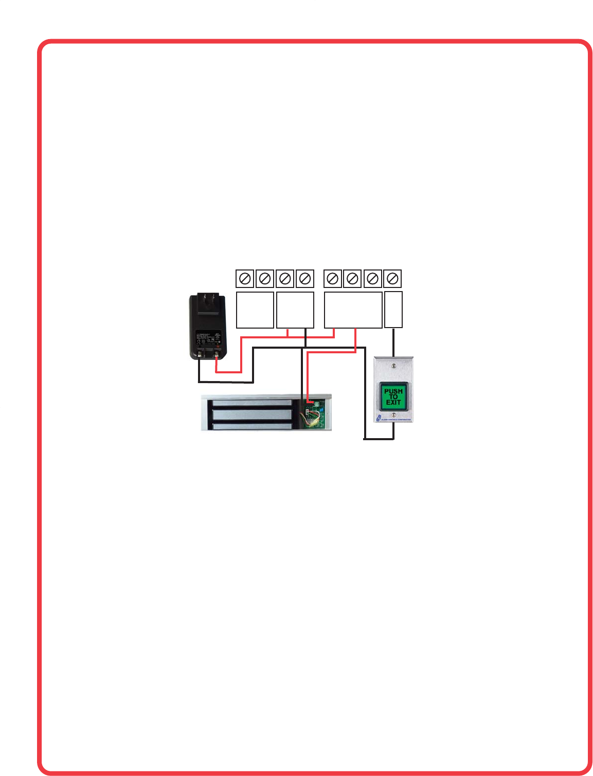
BASIC WIRING DIAGRAM LNB-6 WITH KP-100 KEYPAD
24 VDC PLUG-IN
POWER SUPPLY
EG
IN
N/C
TAMPER
SWITCH
12/24V
AC/DC
+
OUTPUT
N/C C N/O
-
CONNECT TO
NORMALLY-OPEN
TERMINALS OF
TS-2
