Alarm Lock NETDK NETPDK_WI1881.05_INST Trilogy Networx & NETPDK Installation Instructions WI1881.05 INST
User Manual: Alarm Lock Trilogy Networx NETDK & NETPDK Installation Instructions Installation Manuals
Open the PDF directly: View PDF ![]() .
.
Page Count: 1
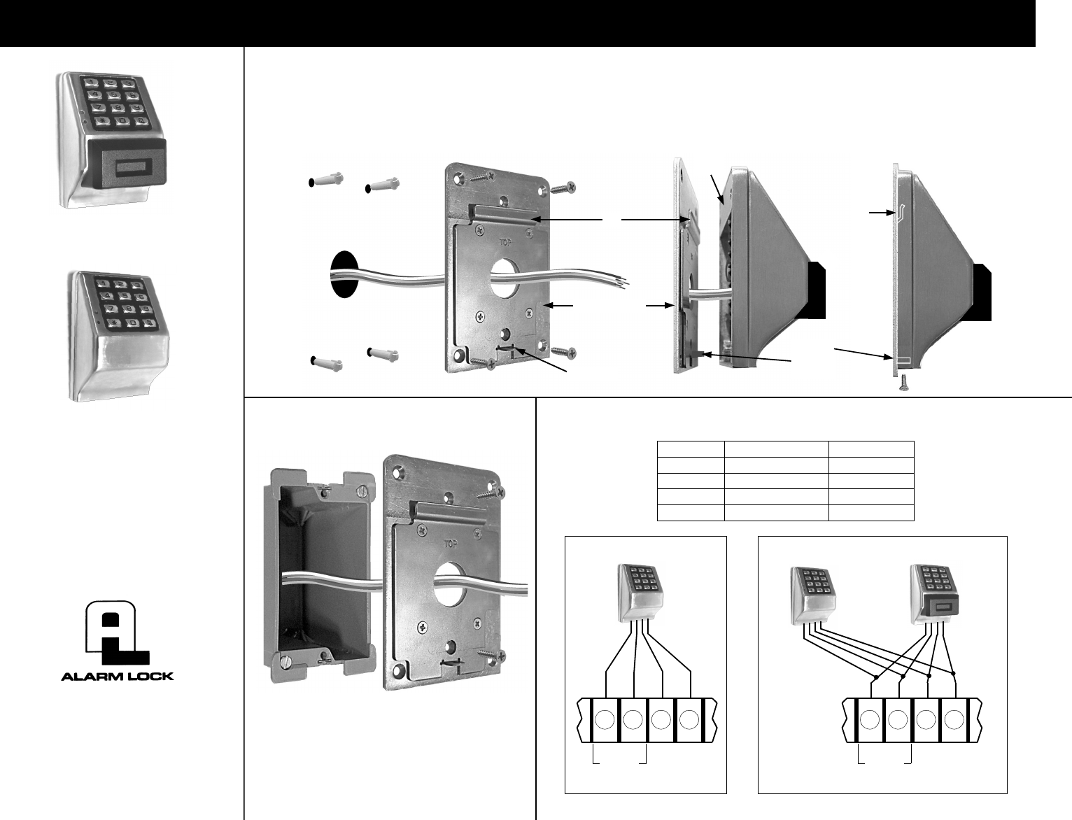
NETDK & NETPDK Installation Instructions
1. Use Mounting Plate as a
template to trace and drill
four 7/32" diameter holes
for wall anchors and 1"
hole for wires.
2. Pull all existing
wires through
wall and
Mounting Plate.
3. Position Mounting Plate and
fasten with four wall anchor
screws. Connect wires as
necessary using wire nuts
supplied. Push wires inside.**
4. Position unit so that the
Short Plate can be placed
over the lip on the Mounting
Plate.
5. Press unit flush with Mount-
ing Plate and pull down.
Fasten with screw.
WALL INSTALLATION
WI1881 10/10
A. Pull all existing wires
through wall Gang Box
and Mounting Plate.
B. Position Mounting Plate
and fasten with two
flathead screws
GANG BOX INSTALLATION
Mounting Plate
Short
Plate
Lip
Screw
tab must
be inside
Screw tab
WIRE COLORS AND CONNECTIONS
Lip
NETPDK
NETDK
TRILOGY NETWORX™
NETDK & NETPDK
SECURED SINGLE-DOOR
OR DOUBLE-DOOR
DIGITAL KEYPADS
345 Bayview Avenue
Amityville, New York 11701
For Sales and Repairs 1-800-ALA-LOCK
For Technical Service 1-800-645-9440
Publicly traded on NASDAQ Symbol: NSSC
© ALARM LOCK 2010
COLOR FUNCTION TERMINAL
RED (12V POWER) T12
BLACK (PWR GROUND) T13
GREEN (RX DATA) T15
YELLOW (TX DATA) T14
(+) (–) TX
(YEL)
RX
(GRN)
KYPD PWR
T12 T13 T14 T15
NETDK (OR NETPDK)
(+) (–) TX
(YEL)
RX
(GRN)
KYPD PWR
T12 T13 T14 T15
SECONDARY
PRIMARY
Red
Black
Yellow
Green
(NETDK
OR
NETPDK)
